EP3466820A1 - Dispositif de cerclage de pièces d'emballage - Google Patents
Dispositif de cerclage de pièces d'emballage Download PDFInfo
- Publication number
- EP3466820A1 EP3466820A1 EP17194938.1A EP17194938A EP3466820A1 EP 3466820 A1 EP3466820 A1 EP 3466820A1 EP 17194938 A EP17194938 A EP 17194938A EP 3466820 A1 EP3466820 A1 EP 3466820A1
- Authority
- EP
- European Patent Office
- Prior art keywords
- lance
- strapping
- tape guide
- chain links
- package
- Prior art date
- Legal status (The legal status is an assumption and is not a legal conclusion. Google has not performed a legal analysis and makes no representation as to the accuracy of the status listed.)
- Granted
Links
- 238000004806 packaging method and process Methods 0.000 title 1
- 238000012856 packing Methods 0.000 claims abstract description 11
- 210000002414 leg Anatomy 0.000 claims abstract description 9
- 210000000689 upper leg Anatomy 0.000 claims abstract description 4
- 239000000463 material Substances 0.000 claims description 6
- 230000007423 decrease Effects 0.000 claims 1
- 238000010276 construction Methods 0.000 abstract 1
- 238000005452 bending Methods 0.000 description 2
- 230000003247 decreasing effect Effects 0.000 description 2
- 238000004519 manufacturing process Methods 0.000 description 2
- 239000002184 metal Substances 0.000 description 2
- 238000000034 method Methods 0.000 description 2
- 230000000295 complement effect Effects 0.000 description 1
- 230000005484 gravity Effects 0.000 description 1
Images


Classifications
-
- B—PERFORMING OPERATIONS; TRANSPORTING
- B65—CONVEYING; PACKING; STORING; HANDLING THIN OR FILAMENTARY MATERIAL
- B65B—MACHINES, APPARATUS OR DEVICES FOR, OR METHODS OF, PACKAGING ARTICLES OR MATERIALS; UNPACKING
- B65B13/00—Bundling articles
- B65B13/02—Applying and securing binding material around articles or groups of articles, e.g. using strings, wires, strips, bands or tapes
- B65B13/04—Applying and securing binding material around articles or groups of articles, e.g. using strings, wires, strips, bands or tapes with means for guiding the binding material around the articles prior to severing from supply
- B65B13/08—Single guide or carrier for the free end of material movable part-away around articles from one side only
-
- B—PERFORMING OPERATIONS; TRANSPORTING
- B65—CONVEYING; PACKING; STORING; HANDLING THIN OR FILAMENTARY MATERIAL
- B65B—MACHINES, APPARATUS OR DEVICES FOR, OR METHODS OF, PACKAGING ARTICLES OR MATERIALS; UNPACKING
- B65B13/00—Bundling articles
- B65B13/18—Details of, or auxiliary devices used in, bundling machines or bundling tools
- B65B13/185—Details of tools
- B65B13/187—Motor means
-
- B—PERFORMING OPERATIONS; TRANSPORTING
- B65—CONVEYING; PACKING; STORING; HANDLING THIN OR FILAMENTARY MATERIAL
- B65B—MACHINES, APPARATUS OR DEVICES FOR, OR METHODS OF, PACKAGING ARTICLES OR MATERIALS; UNPACKING
- B65B57/00—Automatic control, checking, warning, or safety devices
- B65B57/02—Automatic control, checking, warning, or safety devices responsive to absence, presence, abnormal feed, or misplacement of binding or wrapping material, containers, or packages
- B65B57/04—Automatic control, checking, warning, or safety devices responsive to absence, presence, abnormal feed, or misplacement of binding or wrapping material, containers, or packages and operating to control, or to stop, the feed of such material, containers, or packages
Definitions
- the invention relates to a device for strapping packages with a strapping, with a packing space for the package to be strapped portal-like tape guide bow, with two upright side legs and a lying thigh, through which the package across the strapping plane spanned by the band guide sheet strapping with a conveyor can be moved and with at least one with a drive, between the Band Replacementsbogen portalixie person for moving the package with the conveyor releasing rest position and a Band Entrysbogen portal founded furniture closing work position for strapping the package with strapping displaced, Band Entryslanze, the Band Evaluationsbogen and the Band Evaluationslanze in their working position form a band guide channel for the strapping band, which runs around the packing space and has means for releasing the strapping band at its inner sides facing the packing space has from the tape guide channel in the direction of the packing space.
- Such strapping machines ( DE10 2007 019 605 A1 . AT 347 355 A ) are used to fix packages for transport on pallets by means of straps.
- the packages stacked on pallets (load) are automatically conveyed to the strapping machine by means of conveyors.
- the strap is fed from a supply of tape via a tape feed to the strapping machine.
- the load is generated by a lifting hub raised, rotated 90 ° and strapped again.
- the finished strapped cargo is carried out of the machine with the conveyor.
- the tape guide must be open at the bottom of the tape guide bow to allow for infeed and outfeed of the pallet, as the strap may not be passed over the pallet footings.
- drives for this purpose a lance displaceable near the bottom in the lance longitudinal direction between the boards of the pallet base at least approximately parallel to the floor through in the opposite recording, the lance mouth.
- the band guide channel is circumferentially closed around the package and the strapping band can be applied around the package. This process is carried out in parallel and / or repeated depending on the number of strapping required per load.
- the package can also be additionally pressed with a press ram when strapping.
- the invention is therefore an object of the invention to provide a device of the type described above, which requires a lower than the prior art setting range, in particular, the required adjustment width of the device in the direction of Umreifungsebene be reduced.
- the invention solves the problem set by the fact that the tape guide lance consists of a plurality of chain links connected to the drive via a Deflection by at least approximately 90 ° between the band guide arch portal bottom side closing, lying working position and the band guide arch portal floor side releasing rest position are displaced.
- the tape guide lance in its rest position does not significantly increase the footprint of the device in the direction of the strapping.
- the tape guide lance is arranged in its rest position either parallel to the side legs of the tape guide arc at least much, so next to the side legs vertically standing and not parallel to the ground, or at least in its rest position is arranged perpendicular to the strapping, so not laterally from the device ( protrudes parallel to the strapping plane), but comes to lie substantially parallel to the package main conveying direction through the strapping device.
- the chain structure allow this diversion.
- the tape guide lance according to the invention consists of several individually interconnected articulated elements, wherein depending on the number and length of the individual elements a wide variety of lance lengths can be realized.
- the tape guide lance according to the invention is mounted on one side of the machine and moves through the pallet floor in the lance mouth on the opposite side of the machine. While a rigid lance due to gravity according to the bending line, similar to a cantilevered support, curves down, act in the tape guide lance invention further negative factors such as higher weight, manufacturing tolerances and games in the joints with, whereby the tape guide lance sags without additional measures due to the factors mentioned in their working position much stronger down than a comparable rigid tape guide lance. This reduction must be compensated to the extent that the tape guide lance does not hit the pallet during operation and hits the lance jaw safely.
- the abutment surfaces of adjoining chain links in the working position may each be inclined to the associated chain link longitudinal axis and the pivot axis normal transverse axis that the chain link longitudinal axes of adjacent chain links in the direction of the lance tip curved upward.
- the one-sided clamped carrier, the tape guide lance is thus biased so that there is no deflection for the tape guide lance in working position ideally at the lance tip.
- the deflection of the tape guide lance by its own weight is thus counteracted that a theoretically massless tape guide lance would be bent at the lance tip by a corresponding amount upwards.
- a chain link associated abutment surfaces For this purpose, for example, be associated with the transverse axis of the front end by 34 ° and the rear in the lance longitudinal direction by 33, 7 to 33.9 °, in particular by 33, 8 °, inclined to the transverse axis of the opposite ends of a chain link associated abutment surfaces.
- a "not preloaded” and a "prestressed” so in the area of the lance tip "unbiased” and in the lance end "prestressed" chain links are used, the selection of the chain links to be used depends on the weight and length of the tape guide lance.
- the minimal change in the angle of inclination of the stop surfaces in the prestressed chain links causes the deflection is compensated due to its own weight and the lance straightened relative to the total length.
- one or more of these prestressed chain links can be used.
- chain links may have different material densities in the longitudinal direction of the lance, with the material density decreasing in groups in the lance longitudinal direction towards the lance tip.
- chain links made of metal, light metal and plastic could be used in the lance longitudinal direction from the end of the lance to the point of the lance.
- the tape guide lance is driven by an electric motor, wherein the travel of the tape guide lance in both directions of travel is adjusted by means of sensors.
- the tape guide lance invention requires a stronger drive because when pulling out of the machine, the weight of the lance are lifted got to.
- Each direction of movement two sensors are provided, one acts as a "pre-stop” and the second as a "stop” sensor.
- the tape guide lance drive motor is switched off
- the travel time of the lifting lance can be monitored until the end positions are reached, should the tape guide lance collide against the pallet (eg if the load is not correctly positioned in the device or the lowering of the lashing guide lance) permissible value)
- a slip clutch decouples the drive from the tape guiding lance in order to avoid greater damage.
- the device according to the invention for strapping packages with a strapping band comprises a, a packing space 1 for the package 2 to be strapped portal-like tape guide sheet 3, with two upright side legs 4, 5 and a lying thigh 6, through which the package 2 transverse to the tape guide bow third strapped strapping with a conveyor 7 can be brought.
- at least one tape guide lance 9 is provided which is displaceable with a drive 8, between the band guide arch 3 portalboden medicine for moving the package 2 with the conveyor 7 releasing rest position and a Band Evaluationsbogen 3 portalboden furniture closing working position for strapping the package 2 with strapping.
- the tape guide sheet 3 and the tape guide lance 9 in their working position form a circulating around the packing space tape guide channel 11 for the Umreifungsband having on its the packing space 1 facing inner side means for releasing the Umreifungsbandes from the tape guide channel 3 in the direction of the packing space 1.
- the strapping device rests on the portal floor 10.
- the tape guide lance consists of a plurality of chain links 12, the at least approximately 90 ° about a deflection 13 with the drive 8 between the belt guide sheet 3 portal foundedsee side closing, horizontally lying working position ( Fig. 1 and 2 ) and the band guide arch portal floor side releasing, vertically standing, rest position ( Fig. 3 ) are relocatable.
- the tape guide lance 9 is guided in its rest position to the side legs of the tape guide sheet 3 at least for the most part parallel in a housing 14 adjacent to the side legs 5.
- the band guide lance 9 in its rest position could also be arranged at least substantially perpendicular to the strapping plane, ie lying on the portal floor, but parallel to the conveying direction of the conveyor.
- the chain links 12 are pivotally limited to one another in a pivoting direction R in such a way that adjacent chain links 12 in each case rest in their working position on the front side, and complement each other to form a self-supporting band guide lance 9.
- the chain links can be pivoted to move the tape guide lance 9 between its horizontal working position and its vertical rest position accordingly.
- the chain links 13 in the region of the tape guide lance top 14 are associated with one end connecting plates 15 which are fixedly connected to the chain links 13, for example, riveted and which are connected by means of the connecting pin 16 hinged to a trained by chain link 12 bearing block 18, the other end of the tape guide lance top 14 of Chain links is provided.
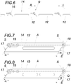
- the chain links 12 in the region of the tape guide lance top side 14 via connecting lugs 15 and connecting pins 16 are pivotally connected such that the end-side abutment surfaces 17 of the chain links 12 are in a running through the pivot axis S stop plane E.
- the abutment surfaces 17 in the embodiment according to Fig. 7 are the abutment surfaces 17 by an angle a, in particular by 34 °, inclined to a normal to Kettengliedlticiansachse- A and the pivot axis transverse axis Q.
- the abutment surfaces 17 of adjoining chain links are inclined in the working position depending on the associated Kettengliedl Kunststoffsachse- A and the pivot axis normal transverse axis Q, that the chain link longitudinal axes A directly adjacent to each other chain links 12 are curved upwards.
- This can be achieved, for example, by the stop faces 17 associated with the opposite ends of a chain link which are inclined by 34 ° in the longitudinal direction of the lance and by an angle ⁇ , in particular by 33 °, 8 °, relative to the transverse axis Q, in the longitudinal direction of the lance.
- the rear in the lance longitudinal direction by 34 ° and the front in the lance longitudinal direction by 34.1 to 34.3 °, in particular by 34, 2 °, could be inclined to the transverse axis Q.
- the chain links may have different material densities in the longitudinal direction of the lance, with the material density preferably decreasing in groups in the longitudinal direction of the lance towards the lance tip.
Landscapes
- Engineering & Computer Science (AREA)
- Mechanical Engineering (AREA)
- Basic Packing Technique (AREA)
Priority Applications (4)
| Application Number | Priority Date | Filing Date | Title |
|---|---|---|---|
| ES17194938T ES2795691T3 (es) | 2017-10-05 | 2017-10-05 | Dispositivo para flejar paquetes |
| SI201730273T SI3466820T1 (sl) | 2017-10-05 | 2017-10-05 | Naprava za povezovanje tovorkov s trakom |
| EP17194938.1A EP3466820B1 (fr) | 2017-10-05 | 2017-10-05 | Dispositif de cerclage de pièces d'emballage |
| PL17194938T PL3466820T3 (pl) | 2017-10-05 | 2017-10-05 | Urządzenie do opasywania pakunków |
Applications Claiming Priority (1)
| Application Number | Priority Date | Filing Date | Title |
|---|---|---|---|
| EP17194938.1A EP3466820B1 (fr) | 2017-10-05 | 2017-10-05 | Dispositif de cerclage de pièces d'emballage |
Publications (2)
| Publication Number | Publication Date |
|---|---|
| EP3466820A1 true EP3466820A1 (fr) | 2019-04-10 |
| EP3466820B1 EP3466820B1 (fr) | 2020-03-04 |
Family
ID=60021988
Family Applications (1)
| Application Number | Title | Priority Date | Filing Date |
|---|---|---|---|
| EP17194938.1A Active EP3466820B1 (fr) | 2017-10-05 | 2017-10-05 | Dispositif de cerclage de pièces d'emballage |
Country Status (4)
| Country | Link |
|---|---|
| EP (1) | EP3466820B1 (fr) |
| ES (1) | ES2795691T3 (fr) |
| PL (1) | PL3466820T3 (fr) |
| SI (1) | SI3466820T1 (fr) |
Cited By (2)
| Publication number | Priority date | Publication date | Assignee | Title |
|---|---|---|---|---|
| WO2021013365A1 (fr) * | 2019-07-22 | 2021-01-28 | Ergopack Deutschland Gmbh | Dispositif et procédé pour cercler des marchandises emballées |
| IT201900019379A1 (it) * | 2019-10-21 | 2021-04-21 | Triatech S R L | Gruppo di lancio perfezionato per reggiatrice a guida traslante |
Citations (8)
| Publication number | Priority date | Publication date | Assignee | Title |
|---|---|---|---|---|
| US3182586A (en) * | 1963-01-24 | 1965-05-11 | Stanley Works | Press apparatus for package compressing and strapping |
| DE2456089A1 (de) * | 1973-12-11 | 1975-06-12 | Signode Corp | Umschnuerungsvorrichtung mit einer gelenkigen bandrinne und einer diese rinne verschiebbar aufnehmenden fuehrungseinrichtung |
| DE2714224A1 (de) * | 1976-04-03 | 1977-10-20 | Gerrard Ind Ltd | Bindevorrichtung zum sichern einer last auf einer palette |
| AT347355B (de) | 1975-04-29 | 1978-12-27 | Fmc Corp | Umreifungsmaschine |
| DE102007019605A1 (de) | 2007-04-24 | 2008-11-06 | Cyklop Gmbh | Umreifungsmaschine |
| DE102011121946A1 (de) * | 2011-12-22 | 2013-06-27 | Itw Packaging Systems Group Gmbh | Vorrichtung zum Umreifen von Packstücken |
| EP2712817A1 (fr) * | 2012-09-28 | 2014-04-02 | ErgoPack Deutschland GmbH | Dispositif de cerclage |
| WO2014096907A1 (fr) * | 2012-12-20 | 2014-06-26 | Itw Packaging Systems Group Gmbh | Appareil de cerclage d'emballages |
-
2017
- 2017-10-05 EP EP17194938.1A patent/EP3466820B1/fr active Active
- 2017-10-05 PL PL17194938T patent/PL3466820T3/pl unknown
- 2017-10-05 ES ES17194938T patent/ES2795691T3/es active Active
- 2017-10-05 SI SI201730273T patent/SI3466820T1/sl unknown
Patent Citations (8)
| Publication number | Priority date | Publication date | Assignee | Title |
|---|---|---|---|---|
| US3182586A (en) * | 1963-01-24 | 1965-05-11 | Stanley Works | Press apparatus for package compressing and strapping |
| DE2456089A1 (de) * | 1973-12-11 | 1975-06-12 | Signode Corp | Umschnuerungsvorrichtung mit einer gelenkigen bandrinne und einer diese rinne verschiebbar aufnehmenden fuehrungseinrichtung |
| AT347355B (de) | 1975-04-29 | 1978-12-27 | Fmc Corp | Umreifungsmaschine |
| DE2714224A1 (de) * | 1976-04-03 | 1977-10-20 | Gerrard Ind Ltd | Bindevorrichtung zum sichern einer last auf einer palette |
| DE102007019605A1 (de) | 2007-04-24 | 2008-11-06 | Cyklop Gmbh | Umreifungsmaschine |
| DE102011121946A1 (de) * | 2011-12-22 | 2013-06-27 | Itw Packaging Systems Group Gmbh | Vorrichtung zum Umreifen von Packstücken |
| EP2712817A1 (fr) * | 2012-09-28 | 2014-04-02 | ErgoPack Deutschland GmbH | Dispositif de cerclage |
| WO2014096907A1 (fr) * | 2012-12-20 | 2014-06-26 | Itw Packaging Systems Group Gmbh | Appareil de cerclage d'emballages |
Cited By (5)
| Publication number | Priority date | Publication date | Assignee | Title |
|---|---|---|---|---|
| WO2021013365A1 (fr) * | 2019-07-22 | 2021-01-28 | Ergopack Deutschland Gmbh | Dispositif et procédé pour cercler des marchandises emballées |
| JP2022543969A (ja) * | 2019-07-22 | 2022-10-17 | エルゴパック・ドイチュラント・ゲーエムベーハー | 梱包された品物をストラップで固定するための機器および方法 |
| JP7323650B2 (ja) | 2019-07-22 | 2023-08-08 | エルゴパック・ドイチュラント・ゲーエムベーハー | 梱包された品物をストラップで固定するための機器および方法 |
| US12084212B2 (en) | 2019-07-22 | 2024-09-10 | Ergopack Deutschland Gmbh | Apparatus and method for strapping packaged goods |
| IT201900019379A1 (it) * | 2019-10-21 | 2021-04-21 | Triatech S R L | Gruppo di lancio perfezionato per reggiatrice a guida traslante |
Also Published As
| Publication number | Publication date |
|---|---|
| SI3466820T1 (sl) | 2020-07-31 |
| ES2795691T3 (es) | 2020-11-24 |
| PL3466820T3 (pl) | 2020-08-10 |
| EP3466820B1 (fr) | 2020-03-04 |
Similar Documents
| Publication | Publication Date | Title |
|---|---|---|
| EP2412650B1 (fr) | Dispositif de stockage pour récipients et procédé de stockage de récipients | |
| EP2377762B1 (fr) | Dispositif et procédé destinés à l'enveloppement d'une pile de marchandise à l'aide d'une feuille | |
| DE8801643U1 (de) | Bandförderer mit umklappbarem Band | |
| DE2137827B2 (de) | Entladevorrichtung | |
| DE102009030012A1 (de) | Produktgreifer | |
| DE3315078C2 (de) | Bandförderer für die senkrechte oder steile Förderung von Schüttgut | |
| EP3466820B1 (fr) | Dispositif de cerclage de pièces d'emballage | |
| DE4401818C2 (de) | Klemmeinrichtung, insbesondere zum Einklemmen eines Bogenpakets beim Stapelwechsel in Stapelvorrichtungen für Papier- oder Kartonbögen | |
| DE1561975A1 (de) | Anlage zum Binden laenglicher Buendel | |
| EP0425869A2 (fr) | Convoyeur à la sortie d'une presse d'extrusion | |
| DE2006210A1 (de) | Transportvorrichtung | |
| DE102008037457A1 (de) | Förderband für eine Streckenförderanlage auf Tragseilen oder Längsschienen | |
| DE2118818B2 (de) | U-förmiger Greifhaken | |
| DE2452420A1 (de) | Vorrichtung um einen gegenstandstraeger auf eine mehrzahl von gegenstaenden aufzubringen | |
| EP3609819B1 (fr) | Arrangement et procédé de formation de récipients | |
| EP1447356B1 (fr) | Convoyeur à rouleaux pour le transport et/ou le stockage d'articles | |
| DE3710722C2 (fr) | ||
| DE3442978A1 (de) | Stueckgutfoerderer | |
| DE102006053913B4 (de) | Fördereinrichtung für Lastträger | |
| WO1996018563A1 (fr) | Convoyeur incline de transport en pente raide ou verticale de materiaux en vrac | |
| DE19520107A1 (de) | Vakuum-Eingabegerät | |
| EP0733550B1 (fr) | Dispositif pour botteler des produits semi-finis oblongs | |
| DE2723782C3 (de) | Be- und Entpalettiervorrichtung für kreiszylindrische Behälter, insbesondere Fässer, in Liegendanordnung nut Formzwischenpaletten | |
| WO1998023507A9 (fr) | Transporteur a chaine | |
| DE202005014323U1 (de) | Vorrichtung zum Stapeln von Dachpfannen |
Legal Events
| Date | Code | Title | Description |
|---|---|---|---|
| PUAI | Public reference made under article 153(3) epc to a published international application that has entered the european phase |
Free format text: ORIGINAL CODE: 0009012 |
|
| STAA | Information on the status of an ep patent application or granted ep patent |
Free format text: STATUS: THE APPLICATION HAS BEEN PUBLISHED |
|
| AK | Designated contracting states |
Kind code of ref document: A1 Designated state(s): AL AT BE BG CH CY CZ DE DK EE ES FI FR GB GR HR HU IE IS IT LI LT LU LV MC MK MT NL NO PL PT RO RS SE SI SK SM TR |
|
| AX | Request for extension of the european patent |
Extension state: BA ME |
|
| STAA | Information on the status of an ep patent application or granted ep patent |
Free format text: STATUS: REQUEST FOR EXAMINATION WAS MADE |
|
| 17P | Request for examination filed |
Effective date: 20191008 |
|
| RBV | Designated contracting states (corrected) |
Designated state(s): AL AT BE BG CH CY CZ DE DK EE ES FI FR GB GR HR HU IE IS IT LI LT LU LV MC MK MT NL NO PL PT RO RS SE SI SK SM TR |
|
| GRAP | Despatch of communication of intention to grant a patent |
Free format text: ORIGINAL CODE: EPIDOSNIGR1 |
|
| STAA | Information on the status of an ep patent application or granted ep patent |
Free format text: STATUS: GRANT OF PATENT IS INTENDED |
|
| INTG | Intention to grant announced |
Effective date: 20191128 |
|
| RAP1 | Party data changed (applicant data changed or rights of an application transferred) |
Owner name: PAMMINGER VERPACKUNGSTECHNIK GES.M.B.H. |
|
| GRAS | Grant fee paid |
Free format text: ORIGINAL CODE: EPIDOSNIGR3 |
|
| GRAA | (expected) grant |
Free format text: ORIGINAL CODE: 0009210 |
|
| STAA | Information on the status of an ep patent application or granted ep patent |
Free format text: STATUS: THE PATENT HAS BEEN GRANTED |
|
| AK | Designated contracting states |
Kind code of ref document: B1 Designated state(s): AL AT BE BG CH CY CZ DE DK EE ES FI FR GB GR HR HU IE IS IT LI LT LU LV MC MK MT NL NO PL PT RO RS SE SI SK SM TR |
|
| REG | Reference to a national code |
Ref country code: GB Ref legal event code: FG4D Free format text: NOT ENGLISH |
|
| REG | Reference to a national code |
Ref country code: CH Ref legal event code: EP |
|
| REG | Reference to a national code |
Ref country code: AT Ref legal event code: REF Ref document number: 1240104 Country of ref document: AT Kind code of ref document: T Effective date: 20200315 |
|
| REG | Reference to a national code |
Ref country code: DE Ref legal event code: R096 Ref document number: 502017004070 Country of ref document: DE |
|
| REG | Reference to a national code |
Ref country code: IE Ref legal event code: FG4D Free format text: LANGUAGE OF EP DOCUMENT: GERMAN |
|
| PG25 | Lapsed in a contracting state [announced via postgrant information from national office to epo] |
Ref country code: NO Free format text: LAPSE BECAUSE OF FAILURE TO SUBMIT A TRANSLATION OF THE DESCRIPTION OR TO PAY THE FEE WITHIN THE PRESCRIBED TIME-LIMIT Effective date: 20200604 Ref country code: FI Free format text: LAPSE BECAUSE OF FAILURE TO SUBMIT A TRANSLATION OF THE DESCRIPTION OR TO PAY THE FEE WITHIN THE PRESCRIBED TIME-LIMIT Effective date: 20200304 Ref country code: RS Free format text: LAPSE BECAUSE OF FAILURE TO SUBMIT A TRANSLATION OF THE DESCRIPTION OR TO PAY THE FEE WITHIN THE PRESCRIBED TIME-LIMIT Effective date: 20200304 |
|
| REG | Reference to a national code |
Ref country code: NL Ref legal event code: MP Effective date: 20200304 |
|
| PG25 | Lapsed in a contracting state [announced via postgrant information from national office to epo] |
Ref country code: GR Free format text: LAPSE BECAUSE OF FAILURE TO SUBMIT A TRANSLATION OF THE DESCRIPTION OR TO PAY THE FEE WITHIN THE PRESCRIBED TIME-LIMIT Effective date: 20200605 Ref country code: HR Free format text: LAPSE BECAUSE OF FAILURE TO SUBMIT A TRANSLATION OF THE DESCRIPTION OR TO PAY THE FEE WITHIN THE PRESCRIBED TIME-LIMIT Effective date: 20200304 Ref country code: SE Free format text: LAPSE BECAUSE OF FAILURE TO SUBMIT A TRANSLATION OF THE DESCRIPTION OR TO PAY THE FEE WITHIN THE PRESCRIBED TIME-LIMIT Effective date: 20200304 Ref country code: LV Free format text: LAPSE BECAUSE OF FAILURE TO SUBMIT A TRANSLATION OF THE DESCRIPTION OR TO PAY THE FEE WITHIN THE PRESCRIBED TIME-LIMIT Effective date: 20200304 Ref country code: BG Free format text: LAPSE BECAUSE OF FAILURE TO SUBMIT A TRANSLATION OF THE DESCRIPTION OR TO PAY THE FEE WITHIN THE PRESCRIBED TIME-LIMIT Effective date: 20200604 |
|
| REG | Reference to a national code |
Ref country code: LT Ref legal event code: MG4D |
|
| PG25 | Lapsed in a contracting state [announced via postgrant information from national office to epo] |
Ref country code: NL Free format text: LAPSE BECAUSE OF FAILURE TO SUBMIT A TRANSLATION OF THE DESCRIPTION OR TO PAY THE FEE WITHIN THE PRESCRIBED TIME-LIMIT Effective date: 20200304 |
|
| PG25 | Lapsed in a contracting state [announced via postgrant information from national office to epo] |
Ref country code: PT Free format text: LAPSE BECAUSE OF FAILURE TO SUBMIT A TRANSLATION OF THE DESCRIPTION OR TO PAY THE FEE WITHIN THE PRESCRIBED TIME-LIMIT Effective date: 20200729 Ref country code: LT Free format text: LAPSE BECAUSE OF FAILURE TO SUBMIT A TRANSLATION OF THE DESCRIPTION OR TO PAY THE FEE WITHIN THE PRESCRIBED TIME-LIMIT Effective date: 20200304 Ref country code: CZ Free format text: LAPSE BECAUSE OF FAILURE TO SUBMIT A TRANSLATION OF THE DESCRIPTION OR TO PAY THE FEE WITHIN THE PRESCRIBED TIME-LIMIT Effective date: 20200304 Ref country code: EE Free format text: LAPSE BECAUSE OF FAILURE TO SUBMIT A TRANSLATION OF THE DESCRIPTION OR TO PAY THE FEE WITHIN THE PRESCRIBED TIME-LIMIT Effective date: 20200304 Ref country code: RO Free format text: LAPSE BECAUSE OF FAILURE TO SUBMIT A TRANSLATION OF THE DESCRIPTION OR TO PAY THE FEE WITHIN THE PRESCRIBED TIME-LIMIT Effective date: 20200304 Ref country code: SM Free format text: LAPSE BECAUSE OF FAILURE TO SUBMIT A TRANSLATION OF THE DESCRIPTION OR TO PAY THE FEE WITHIN THE PRESCRIBED TIME-LIMIT Effective date: 20200304 Ref country code: SK Free format text: LAPSE BECAUSE OF FAILURE TO SUBMIT A TRANSLATION OF THE DESCRIPTION OR TO PAY THE FEE WITHIN THE PRESCRIBED TIME-LIMIT Effective date: 20200304 Ref country code: IS Free format text: LAPSE BECAUSE OF FAILURE TO SUBMIT A TRANSLATION OF THE DESCRIPTION OR TO PAY THE FEE WITHIN THE PRESCRIBED TIME-LIMIT Effective date: 20200704 |
|
| REG | Reference to a national code |
Ref country code: ES Ref legal event code: FG2A Ref document number: 2795691 Country of ref document: ES Kind code of ref document: T3 Effective date: 20201124 |
|
| REG | Reference to a national code |
Ref country code: DE Ref legal event code: R097 Ref document number: 502017004070 Country of ref document: DE |
|
| PLBE | No opposition filed within time limit |
Free format text: ORIGINAL CODE: 0009261 |
|
| STAA | Information on the status of an ep patent application or granted ep patent |
Free format text: STATUS: NO OPPOSITION FILED WITHIN TIME LIMIT |
|
| PG25 | Lapsed in a contracting state [announced via postgrant information from national office to epo] |
Ref country code: DK Free format text: LAPSE BECAUSE OF FAILURE TO SUBMIT A TRANSLATION OF THE DESCRIPTION OR TO PAY THE FEE WITHIN THE PRESCRIBED TIME-LIMIT Effective date: 20200304 |
|
| 26N | No opposition filed |
Effective date: 20201207 |
|
| REG | Reference to a national code |
Ref country code: CH Ref legal event code: PL |
|
| PG25 | Lapsed in a contracting state [announced via postgrant information from national office to epo] |
Ref country code: MC Free format text: LAPSE BECAUSE OF FAILURE TO SUBMIT A TRANSLATION OF THE DESCRIPTION OR TO PAY THE FEE WITHIN THE PRESCRIBED TIME-LIMIT Effective date: 20200304 Ref country code: LU Free format text: LAPSE BECAUSE OF NON-PAYMENT OF DUE FEES Effective date: 20201005 |
|
| REG | Reference to a national code |
Ref country code: BE Ref legal event code: MM Effective date: 20201031 |
|
| PG25 | Lapsed in a contracting state [announced via postgrant information from national office to epo] |
Ref country code: LI Free format text: LAPSE BECAUSE OF NON-PAYMENT OF DUE FEES Effective date: 20201031 Ref country code: CH Free format text: LAPSE BECAUSE OF NON-PAYMENT OF DUE FEES Effective date: 20201031 Ref country code: BE Free format text: LAPSE BECAUSE OF NON-PAYMENT OF DUE FEES Effective date: 20201031 |
|
| PG25 | Lapsed in a contracting state [announced via postgrant information from national office to epo] |
Ref country code: IE Free format text: LAPSE BECAUSE OF NON-PAYMENT OF DUE FEES Effective date: 20201005 |
|
| PG25 | Lapsed in a contracting state [announced via postgrant information from national office to epo] |
Ref country code: TR Free format text: LAPSE BECAUSE OF FAILURE TO SUBMIT A TRANSLATION OF THE DESCRIPTION OR TO PAY THE FEE WITHIN THE PRESCRIBED TIME-LIMIT Effective date: 20200304 Ref country code: MT Free format text: LAPSE BECAUSE OF FAILURE TO SUBMIT A TRANSLATION OF THE DESCRIPTION OR TO PAY THE FEE WITHIN THE PRESCRIBED TIME-LIMIT Effective date: 20200304 Ref country code: CY Free format text: LAPSE BECAUSE OF FAILURE TO SUBMIT A TRANSLATION OF THE DESCRIPTION OR TO PAY THE FEE WITHIN THE PRESCRIBED TIME-LIMIT Effective date: 20200304 |
|
| PG25 | Lapsed in a contracting state [announced via postgrant information from national office to epo] |
Ref country code: MK Free format text: LAPSE BECAUSE OF FAILURE TO SUBMIT A TRANSLATION OF THE DESCRIPTION OR TO PAY THE FEE WITHIN THE PRESCRIBED TIME-LIMIT Effective date: 20200304 Ref country code: AL Free format text: LAPSE BECAUSE OF FAILURE TO SUBMIT A TRANSLATION OF THE DESCRIPTION OR TO PAY THE FEE WITHIN THE PRESCRIBED TIME-LIMIT Effective date: 20200304 |
|
| PGFP | Annual fee paid to national office [announced via postgrant information from national office to epo] |
Ref country code: PL Payment date: 20240923 Year of fee payment: 8 |
|
| PGFP | Annual fee paid to national office [announced via postgrant information from national office to epo] |
Ref country code: DE Payment date: 20241029 Year of fee payment: 8 |
|
| PGFP | Annual fee paid to national office [announced via postgrant information from national office to epo] |
Ref country code: GB Payment date: 20241022 Year of fee payment: 8 |
|
| PGFP | Annual fee paid to national office [announced via postgrant information from national office to epo] |
Ref country code: FR Payment date: 20241025 Year of fee payment: 8 Ref country code: AT Payment date: 20241010 Year of fee payment: 8 |
|
| PGFP | Annual fee paid to national office [announced via postgrant information from national office to epo] |
Ref country code: IT Payment date: 20241022 Year of fee payment: 8 Ref country code: ES Payment date: 20241118 Year of fee payment: 8 |
|
| PGFP | Annual fee paid to national office [announced via postgrant information from national office to epo] |
Ref country code: SI Payment date: 20240918 Year of fee payment: 8 |