EP3466894B1 - Behandlung und rückgewinnung von laugen aus verbrauchter lauge durch bioelektrochemische verfahren - Google Patents
Behandlung und rückgewinnung von laugen aus verbrauchter lauge durch bioelektrochemische verfahren Download PDFInfo
- Publication number
- EP3466894B1 EP3466894B1 EP18196952.8A EP18196952A EP3466894B1 EP 3466894 B1 EP3466894 B1 EP 3466894B1 EP 18196952 A EP18196952 A EP 18196952A EP 3466894 B1 EP3466894 B1 EP 3466894B1
- Authority
- EP
- European Patent Office
- Prior art keywords
- chamber
- caustic
- biocatalyst
- mtcc
- electrode
- Prior art date
- Legal status (The legal status is an assumption and is not a legal conclusion. Google has not performed a legal analysis and makes no representation as to the accuracy of the status listed.)
- Active
Links
Images

Classifications
-
- C—CHEMISTRY; METALLURGY
- C02—TREATMENT OF WATER, WASTE WATER, SEWAGE, OR SLUDGE
- C02F—TREATMENT OF WATER, WASTE WATER, SEWAGE, OR SLUDGE
- C02F3/00—Biological treatment of water, waste water, or sewage
- C02F3/005—Combined electrochemical biological processes
-
- C—CHEMISTRY; METALLURGY
- C25—ELECTROLYTIC OR ELECTROPHORETIC PROCESSES; APPARATUS THEREFOR
- C25B—ELECTROLYTIC OR ELECTROPHORETIC PROCESSES FOR THE PRODUCTION OF COMPOUNDS OR NON-METALS; APPARATUS THEREFOR
- C25B9/00—Cells or assemblies of cells; Constructional parts of cells; Assemblies of constructional parts, e.g. electrode-diaphragm assemblies; Process-related cell features
- C25B9/17—Cells comprising dimensionally-stable non-movable electrodes; Assemblies of constructional parts thereof
- C25B9/19—Cells comprising dimensionally-stable non-movable electrodes; Assemblies of constructional parts thereof with diaphragms
- C25B9/23—Cells comprising dimensionally-stable non-movable electrodes; Assemblies of constructional parts thereof with diaphragms comprising ion-exchange membranes in or on which electrode material is embedded
-
- C—CHEMISTRY; METALLURGY
- C02—TREATMENT OF WATER, WASTE WATER, SEWAGE, OR SLUDGE
- C02F—TREATMENT OF WATER, WASTE WATER, SEWAGE, OR SLUDGE
- C02F3/00—Biological treatment of water, waste water, or sewage
- C02F3/006—Regulation methods for biological treatment
-
- C—CHEMISTRY; METALLURGY
- C02—TREATMENT OF WATER, WASTE WATER, SEWAGE, OR SLUDGE
- C02F—TREATMENT OF WATER, WASTE WATER, SEWAGE, OR SLUDGE
- C02F3/00—Biological treatment of water, waste water, or sewage
- C02F3/34—Biological treatment of water, waste water, or sewage characterised by the microorganisms used
- C02F3/341—Consortia of bacteria
-
- C—CHEMISTRY; METALLURGY
- C12—BIOCHEMISTRY; BEER; SPIRITS; WINE; VINEGAR; MICROBIOLOGY; ENZYMOLOGY; MUTATION OR GENETIC ENGINEERING
- C12P—FERMENTATION OR ENZYME-USING PROCESSES TO SYNTHESISE A DESIRED CHEMICAL COMPOUND OR COMPOSITION OR TO SEPARATE OPTICAL ISOMERS FROM A RACEMIC MIXTURE
- C12P11/00—Preparation of sulfur-containing organic compounds
-
- C—CHEMISTRY; METALLURGY
- C25—ELECTROLYTIC OR ELECTROPHORETIC PROCESSES; APPARATUS THEREFOR
- C25B—ELECTROLYTIC OR ELECTROPHORETIC PROCESSES FOR THE PRODUCTION OF COMPOUNDS OR NON-METALS; APPARATUS THEREFOR
- C25B1/00—Electrolytic production of inorganic compounds or non-metals
- C25B1/01—Products
- C25B1/14—Alkali metal compounds
- C25B1/16—Hydroxides
-
- C—CHEMISTRY; METALLURGY
- C25—ELECTROLYTIC OR ELECTROPHORETIC PROCESSES; APPARATUS THEREFOR
- C25B—ELECTROLYTIC OR ELECTROPHORETIC PROCESSES FOR THE PRODUCTION OF COMPOUNDS OR NON-METALS; APPARATUS THEREFOR
- C25B11/00—Electrodes; Manufacture thereof not otherwise provided for
- C25B11/04—Electrodes; Manufacture thereof not otherwise provided for characterised by the material
- C25B11/042—Electrodes formed of a single material
- C25B11/043—Carbon, e.g. diamond or graphene
-
- C—CHEMISTRY; METALLURGY
- C25—ELECTROLYTIC OR ELECTROPHORETIC PROCESSES; APPARATUS THEREFOR
- C25B—ELECTROLYTIC OR ELECTROPHORETIC PROCESSES FOR THE PRODUCTION OF COMPOUNDS OR NON-METALS; APPARATUS THEREFOR
- C25B11/00—Electrodes; Manufacture thereof not otherwise provided for
- C25B11/04—Electrodes; Manufacture thereof not otherwise provided for characterised by the material
- C25B11/051—Electrodes formed of electrocatalysts on a substrate or carrier
- C25B11/055—Electrodes formed of electrocatalysts on a substrate or carrier characterised by the substrate or carrier material
- C25B11/057—Electrodes formed of electrocatalysts on a substrate or carrier characterised by the substrate or carrier material consisting of a single element or compound
-
- C—CHEMISTRY; METALLURGY
- C02—TREATMENT OF WATER, WASTE WATER, SEWAGE, OR SLUDGE
- C02F—TREATMENT OF WATER, WASTE WATER, SEWAGE, OR SLUDGE
- C02F2101/00—Nature of the contaminant
- C02F2101/10—Inorganic compounds
- C02F2101/101—Sulfur compounds
-
- C—CHEMISTRY; METALLURGY
- C02—TREATMENT OF WATER, WASTE WATER, SEWAGE, OR SLUDGE
- C02F—TREATMENT OF WATER, WASTE WATER, SEWAGE, OR SLUDGE
- C02F2209/00—Controlling or monitoring parameters in water treatment
- C02F2209/06—Controlling or monitoring parameters in water treatment pH
-
- C—CHEMISTRY; METALLURGY
- C02—TREATMENT OF WATER, WASTE WATER, SEWAGE, OR SLUDGE
- C02F—TREATMENT OF WATER, WASTE WATER, SEWAGE, OR SLUDGE
- C02F3/00—Biological treatment of water, waste water, or sewage
- C02F3/02—Aerobic processes
-
- C—CHEMISTRY; METALLURGY
- C02—TREATMENT OF WATER, WASTE WATER, SEWAGE, OR SLUDGE
- C02F—TREATMENT OF WATER, WASTE WATER, SEWAGE, OR SLUDGE
- C02F3/00—Biological treatment of water, waste water, or sewage
- C02F3/28—Anaerobic digestion processes
- C02F3/2806—Anaerobic processes using solid supports for microorganisms
-
- Y—GENERAL TAGGING OF NEW TECHNOLOGICAL DEVELOPMENTS; GENERAL TAGGING OF CROSS-SECTIONAL TECHNOLOGIES SPANNING OVER SEVERAL SECTIONS OF THE IPC; TECHNICAL SUBJECTS COVERED BY FORMER USPC CROSS-REFERENCE ART COLLECTIONS [XRACs] AND DIGESTS
- Y02—TECHNOLOGIES OR APPLICATIONS FOR MITIGATION OR ADAPTATION AGAINST CLIMATE CHANGE
- Y02W—CLIMATE CHANGE MITIGATION TECHNOLOGIES RELATED TO WASTEWATER TREATMENT OR WASTE MANAGEMENT
- Y02W10/00—Technologies for wastewater treatment
- Y02W10/10—Biological treatment of water, waste water, or sewage
-
- Y—GENERAL TAGGING OF NEW TECHNOLOGICAL DEVELOPMENTS; GENERAL TAGGING OF CROSS-SECTIONAL TECHNOLOGIES SPANNING OVER SEVERAL SECTIONS OF THE IPC; TECHNICAL SUBJECTS COVERED BY FORMER USPC CROSS-REFERENCE ART COLLECTIONS [XRACs] AND DIGESTS
- Y02—TECHNOLOGIES OR APPLICATIONS FOR MITIGATION OR ADAPTATION AGAINST CLIMATE CHANGE
- Y02W—CLIMATE CHANGE MITIGATION TECHNOLOGIES RELATED TO WASTEWATER TREATMENT OR WASTE MANAGEMENT
- Y02W10/00—Technologies for wastewater treatment
- Y02W10/30—Wastewater or sewage treatment systems using renewable energies
- Y02W10/37—Wastewater or sewage treatment systems using renewable energies using solar energy
Definitions
- the present invention relates to an apparatus and a method for bio-assisted treatment of spent caustic obtained from hydrocarbon and gas processing installations.
- the present invention also relates to method for recovery of caustic and recovery of sulfur from spent caustic.
- Aqueous sodium hydroxide solution is used for removal of sulfides, mercaptans and other sulfur compounds from gaseous and hydrocarbon streams in oil refinery processes. Once these contaminants come in contact and react with caustic solution, it cannot be further utilized and is known as spent caustic.
- the spent caustic contain un-utilized sodium hydroxide with contaminants like sulfides, mercaptans, amines, naphthenic acids, phenols, their derivatives, hydrocarbons and few other inorganic and organic compounds. Due to presence of these contaminants and high salinity and high pH, spent caustics are most difficult of all industrial wastes to dispose properly. Spent caustic is disposed by very expensive and environmentally reactive methods such as high dilutions and then treatment at ETP, deep well injections, incineration, wet air oxidation, humid hydrogen peroxide oxidation etc.
- US 4968622 discloses a biological conversion process for degradation of sulfur-containing pollutants such as H 2 S, CS 2 , COS, and also organic surfur compounds such as thio-alcohols, thio-ethers, and thiophenes in waste gas.
- a packed reactor is provided which has packing material covered with immobilized microorganisms of the family of Thiobacillus and which are continuously kept moist, so that metabolic products of the microorganisms are dissolved in the moisture and discharged continuously.
- a continuous concentration gradient for sulfate ions thereby results in the reactor or in the region of the microorganisms, these sulfate ions being neutralized in a second reactor by supplying lye (soda or potash lye) forming readily-soluble salts.
- US 5480550 discloses a biological process for the disposal for caustic waste streams containing inorganic sulfides to effect neutralization of the caustic and oxidation of sulfides to sulfates.
- the process disclosed in above said patent includes use of flocculated cultures of a sulfide-oxidizing bacterium from the genus Thiobacillus and various heterotrophs.
- the process includes immobilization of the bacteria and use of undefined mixture of microbes which are difficult to replicate. This process suffers from major drawback of immobilizing bacteria by co-culture with at least one floc-forming heterotroph under aerobic conditions to form a flocculated biomass.
- the process of disposal of caustic waste streams is performed at pH of 7.0 and same is maintained by addition of 10N nitric acid solution. Hence, addition of heterotroph and nitric acid results into undesired addition of cost to the disposal process.
- US patent 6,045,695 discloses a process for the biological treatment of spent caustic solution containing sulfides, wherein the solution introduces into an aerobic reactor containing sulfide-oxidizing bacteria, and the sulfides are partly converted to elemental sulfur and partly to sulfate by controlling the redox potential in the reactor at a value below 300mV (against an Ag/AgCl reference electrode), or below -97 (against reference electrode).
- the process suffers from disadvantages like the sulfide oxidation is done by using M. sulfidovorans which result into formation of thiosulfate. Usually thiosulfate is an undesirable component in waste water.
- M. sulfidovorans _ with bacteria like genus Thiobacillus to convert thiosulfate to sulfate and/ or sulfur which ultimately results into increase in the cost of disposal of impurities from spent caustic.
- US 2001/0024351 discloses a method and apparatus for biologically treating a spent caustic to provide a treated spent caustic, said method comprising the steps of: (a) passing a spent caustic stream comprising water, alkali metal hydroxide and sulfide to a first bioreactor; (b) biologically oxidizing sulfide in the first bioreactor with sulfide-oxidizing bacteria like thiobacillus and thiomicrospira ) to form sulfur and sulfate to provide a partially oxidized spent caustic; (c) passing the partially oxidized spent caustic to a second bioreactor where at least a portion of the partially oxidized spent caustic is further oxidized with sulfide-oxidizing bacteria to generate sulfate from sulfur to provide a treated spent caustic comprising sulfate.
- the drawbacks of above said process is that the process requires two bioreactors for treatment of spent caustic resulting into increase in
- Buisman et al 1990 discusses a biotechnological process for sulfide removal from H2S to elemental sulfur. The disclosed process works well at neutral pH.
- Indian Patent Application No. 2480/MUM/2015 entitled "Bio-Assisted Process For Treatment And Regeneration Of Spent Caustic” discloses a bio-assisted method for treatment of spent caustic by treating with haloalkaliphilic consortium of bacteria capable of reducing or transforming sulfides, thiols, mercaptants and other sulphur containing compounds, phenols, hydrocarbons, naphthenic acids and their derivatives in spent caustic.
- sulfides are completely oxidized to sulphate which contributes in increasing the TDS of the effluent.
- Vaiopoulou and co-workers in 2016 ( Eleni Vaiopoulou, Thomas Provijn, Antonin Prévoteau, Ilje Pikaar, Korneel Rabaey, Electrochemical sulfide removal and caustic recovery from spent caustic streams. 2016, 10.1016/j.watres.2016.01.039 ) reported the treatment of defined media simulating spent caustic stream (4 wt% NaOH and 1 wt% Na2S-S). They run the experiment abiotically under constant supply of high current densities (0-200 A/m 2 ) in galvanostat mode and studied different sulfide loading rates of 50-200 g(S)/L/d.
- the present invention relates to an apparatus and method for bio-assisted treatment of spent caustic obtained from hydrocarbon and gas processing installations.
- the present invention also relates to method for recovery of caustic and recovery of sulfur from spent caustic.
- the sulfide removal is about 96% and the sulphur formation and deposition on the electrode lies in range of 72 ⁇ 8%.
- the present invention provides a method for treatment of spent caustic and recovery of caustic and sulphur by bioelectrochemical process, said process comprising the steps of:
- the present invention provides a method for treatment of spent caustic and recovery of caustic and sulphur as claimed in claim 1, wherein step (ii) is combined with step (i) and the biocatalyst (14) is present as biofilm on the electrode (2) in the first chamber, anaerobically oxidizing sulphide and other related compounds to elemental sulfur (15) or its oxidized form by using biocatalyst (14) and recovers sulphur; and feeding effluent (17) to subsequent stage reactor comprising aerobic biocatalyst (18) for treating effluent (17) and discharging completely treated effluent (19) with reduced concentration of sodium hydroxide, sulfides, amines, thiols, sulphur containing compounds, phenols, hydrocarbons, naphthenic acids and their derivatives.
- the present invention provides a method, wherein the microbes in biocatalyst (14) are used in adsorbed form or free form or immobilized on synthetic plastics, surface-modified carbon nanotubes, poly (tetrafluoroethylene) (PTFE) fibrils, zeolite, clay, anthracite, porous glass, activated charcoal, ceramics, acrylamide, polyurethane, polyvinyl, resins and natural polymer.
- PTFE poly (tetrafluoroethylene)
- the present invention provides a method, wherein the pH of second chamber increases and reaches to 12.68 and the associated pH drop of spent caustic is 7.08 in 12 hours.
- the present invention provides a method 7, wherein the sulfide removal is about 96% and the sulphur formation and deposition on the electrode lies in range of 72 ⁇ 8%.
- the present invention provides an apparatus for treatment of spent caustic and recovery of caustic and sulphur, said system comprising:
- the present invention provides an apparatus for treatment of spent caustic and recovery of caustic and sulphur, wherein stage 2 is combined with stage 1 and the biocatalyst (14) is present as biofilm on the electrode (2) in the first chamber of stage 1, anaerobically oxidize sulphide and other related compounds to elemental sulfur (15) or its oxidized form by using biocatalyst (14) and recovers sulphur; and effluent (17) is fed to subsequent stage reactor comprising aerobic biocatalyst (18) for treating effluent (17) and discharging completely treated effluent (19) with reduced concentration of sodium hydroxide, sulfides, amines, thiols, sulphur containing compounds, phenols, hydrocarbons, naphthenic acids and their derivatives.
- the present invention provides an apparatus, wherein in stage 1, electrode (2) in first chamber comprises graphite rod, graphite plate, carbon brush, carbon paper, graphite felt; and electrode (3) in the second chamber comprises a carbon based electrode coated with noble metals, preferably graphite electrode (3) wrapped with stainless steel mesh.
- the present invention provides an apparatus, wherein the sulfide removal is about 96% and the sulphur formation and deposition on the electrode lies in range of 72 ⁇ 8%.
- the present invention relates to a system and method for bio-assisted treatment of spent caustic obtained from hydrocarbon and gas processing installations.
- the present invention also relates to method for recovery of caustic and recovery of sulfur from spent caustic.
- a three stage electro-bio-assisted assisted method of treating spent caustic comprising the steps of:
- apparatus for stage-1 comprise of two chambers separated by cation exchange membrane (CEM).
- CEM cation exchange membrane
- One chamber is inserted with graphite rod wrapped with activated carbon cloth (ACC) and considered as working chamber where the spent caustic treatment occurs.
- the electrodes for this chamber can be varied, viz., graphite plate, carbon brush, carbon paper, graphite felt, etc.
- the other chamber is inserted with graphite electrode wrapped with stainless steel mesh (SS) and considered as counter chamber.
- the counter chamber may be of any carbon based electrodes coated with noble metals.
- One chamber having ACC electrode was fed with spent caustic, while the other chamber was fed with distilled water.
- the spent caustic chamber as well as counter chamber was maintained under anaerobic conditions.
- Both the chambers are equipped with Ag/AgCl (3M KCL) reference electrode. Both these electrodes will be connected through resistance or through power supply.
- the bioreactor can be operated at temperature ranging from 20-40 °C under constant applied voltage in the range of 0.1-5 V or current in the range of 5-250 A/m 2 vs Ag/AgCl reference electrode. The current can be provided from any renewable sources like solar or from electrical grid.
- the bioreactor can be operated in batch mode with a hydraulic retention time (HRT) of 5-48 h or in continuous mode with 2-24h HRT. In continuous mode, spent caustic will fed to the working chamber at a flow rate of 1-20 ml/h and de-ionized water will fed to cathode at a flow rate of 1-25 ml/h.
- HRT hydraulic retention time
- the bioreactor in stage 2 of 3 stage process can be a suspended or packed column reactor having selective bacteria for sulfide oxidation to sulfur.
- the outlet from working chamber of stage-1 bioreactor having lowered pH (7-8) will be fed to this bioreactor and operated under anaerobic conditions.
- the packing material for the bioreactor can be gravel stones, polymeric material, sponge beads, etc.
- the bioreactor can be operated in batch mode with a HRT of 6-24 h or in continuous mode with 2-18h HRT. Continuous mode operation can be at a flow rate of 5-50 ml/h.
- the bioreactor can be operated at temperature ranging from 25-45 °C.
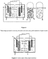
- Fig 2 represents three stage method for treatment of spent caustic and recovery of caustic and sulfur.
- the apparatus for stage-1 comprise of two chambers separated by cation exchange membrane (CEM) 1.
- One chamber is inserted with graphite rod wrapped with activated carbon cloth (ACC) 2 and considered as working chamber where the spent caustic treatment occurs.
- the electrodes for this chamber can be varied, viz., graphite plate, carbon brush, carbon paper, graphite felt, etc.
- the other chamber is inserted with graphite electrode wrapped with stainless steel mesh (SS) 3 and considered as counter chamber.
- the counter chamber may be of any carbon based electrodes coated with noble metals.
- One chamber having ACC electrode 1 was fed with spent caustic 4 , while the other chamber was fed with distilled water 5 .
- the spent caustic chamber as well as counter chamber was maintained under anaerobic conditions. Both the chambers are equipped with Ag/AgCl (3M KCL) reference electrode 6 . Both these electrodes will be connected through resistance or through power supply 7 .
- the spent caustic 4 loaded to the working electrode chamber and distilled water to the counter electrode chamber.
- the cations 8 present in the spent caustic will be exchanged via the CEM 1 to the counter electrode chamber resulting in the lowering of pH 9 to 10 .
- the exchanged cations from working chamber to the counter electrode chamber increase the pH of counter chamber from 11 to 12 , regenerating the caustic 13 , which can be recovered.
- a two-reactor configuration is used in accordance with the invention, where the stage-1 and stage-2 are performed in the same reactor for recovery of caustic and sulfur along with treatment of spent caustic.
- Fig 1 represents the two stage method for treatment of spent caustic and recovery of caustic and sulfur.
- the apparatus for stage-1 comprise of two chambers separated by cation exchange membrane (CEM) 1.
- One chamber is inserted with graphite rod wrapped with activated carbon cloth (ACC) 2 and considered as working chamber where the spent caustic treatment occurs.
- the electrodes for this chamber can be varied, viz., graphite plate, carbon brush, carbon paper, graphite felt, etc.
- the other chamber is inserted with graphite electrode wrapped with stainless steel mesh (SS) 3 and considered as counter chamber.
- the counter chamber may be of any carbon based electrodes coated with noble metals.
- One chamber having ACC electrode 1 was fed with spent caustic 4 , while the other chamber was fed with distilled water 5 .
- the spent caustic chamber as well as counter chamber was maintained under anaerobic conditions. Both the chambers are equipped with Ag/AgCl (3M KCL) reference electrode 6 . Both these electrodes will be connected through resistance or through power supply 7 .
- the spent caustic 4 loaded to the working electrode chamber and distilled water to the counter electrode chamber.
- the cations 8 present in the spent caustic will be exchanged via the CEM 1 to the counter electrode chamber resulting in the lowering of pH 9 to 10 .
- the exchanged cations from working chamber to the counter electrode chamber increase the pH of counter chamber from 11 to 12 , regenerating the caustic 13 , which can be recovered.
- the biocatalyst 14 present in working electrode chamber as biofilm on the electrode and in the suspension will anaerobically oxidize the sulfides present in the spent caustic converting them to elemental sulfur 15 , which can be recovered.
- the effluent from working chamber 16 with low sulfide content and lowered pH will be fed to the reactor in stage-2, where the aerobic biocatalyst 18 will be used for treating the remaining organic content and the completely treated effluent 19 will be discharged.
- the bioreactor in stage-3 for treating the left over contaminants such as hydrocarbons and phenols will in suspended mode added with aerobic bacteria.
- the outlet from the sulfur recovery bioreactor will be fed to this bioreactor and operated under aerobic conditions.
- the bioreactor can be operated in batch mode with a HRT of 2-18 h or in continuous mode with 2-10h HRT. Continuous mode operation can be at a flow rate of 5-50 ml/h.
- the bioreactor can be operated at temperature ranging from 25-45 °C.
- the electrochemical treatment will result in regeneration of caustic at cathode and to increase its pH to 12-14 and decrease the pH of anode to 7-9.
- treatment is done in batch mode as well as continuous mode using continuously stirrer reactor, up-flow reactor and such suitable reactor.
- the method of treatment of spent caustic can be used for recovery of sodium hydroxide from the spent caustic.
- the method of treatment of spent caustic can be used for recovery of elemental sulfur from the spent caustic.
- the spent caustic treated in stage-2 is treated using a microbial consortia in stage 3 which resulted in reduced concentration of sulfides, amines, thiols, other sulphur containing compounds, phenols, hydrocarbons, naphthenic acids and their derivatives at least by 90%.
- the said microbes which can be used in stage 2 includes, but not limited to, Thiobacillus sp, Thiomicrospira sp, Pseudominas putida, alone or in combination with each other.
- the representative species of the biocatalyst (14) are publically available in the depositories and are not claimed by the applicant. All species of these genus will perform the function, however the isolates may be characterized for following features:
- microbe examples include, but not limited to DSM 12475, DSM 5368, DSM 505, DSM 19892, DSM 700, DSM 3134, ATCC 25259, ATCC 23648, ATCC 8158 etc.
- microbe examples include, but not limited to ATCC 700954 DSM13453, ATCC 700955, DSM13458,DSM 1534, DSM 12351, DSM 12352,ATCC 35932,ATCC 700877, ATCC 49871, DSM: 12353,DSM: 13229.
- microbe are, but not limited to Pseudomonas putida MTCC 5388, Pseudomonas putida MTCC 5387.
- the microbes used at stage 2 also can be used in adsorbed form or in free form.
- the bacteria can be immobilized on synthetic plastics, surface-modified carbon nanotubes, poly (tetrafluoroethylene) (PTFE) fibrils, zeolite, clay, anthracite, porous glass, activated charcoal, ceramics, acrylamide, polyurethane, polyvinyl, resins and natural polymer etc.
- PTFE poly (tetrafluoroethylene)
- the method of the stage 2 of treatment of spent caustic use a nutrient system consisting of K 2 HPO 4 (2-10g/l), KH 2 PO 4 (2-15 g/l) , MgCl 2 (0.1-5 g/l), 0.5-2 ml trace elements, sodium carbonate (1-20 g/l), yeast extract (2-10 g/l), ammonium nitrate (3-7 g/l), citrate (1-20 g/l), Oleic acid (10 -1000 ppm), pantothenic acid (2-500 ppm), thiamine (2.5-200 ppm).
- the trace element solution (gram per liter) comprises nitrilotriacetic acid (1.5), FeSO 4 .7H 2 O (0.05), MnCl 2 .4H 2 O (0.015), CoCl 2 .6H 2 O (0.09), CaCl 2 .2H 2 0 (0.50), ZnCl 2 (0.50), CuCl 2 .H 2 O (0.03), H 3 BO 3 (0.02), Na 2 MoO 4 (0.02).
- bioreactor having electrode pair was used in stage-1 followed by bioreactor s with selective microbial consortia in stage-2 and stage-3.
- stage 2 Another embodiment of the present invention relates to the microbes used in stage 2 which can work in pH range 7-9 and oxidized sulfides to elemental sulphur and sulphate where elemental sulphur form is at least 60%.
- the spent caustic treated in stage-2 is treated using a microbial consortia in stage 3 which resulted in reduced concentration of sulfides, amines, thiols, other sulphur containing compounds, phenols, hydrocarbons, naphthenic acids and their derivatives at least by 90%.
- the consortia of bacteria used in stage 3 include Pseudomonas putida (MTCC 5385), Pseudomonas aeruginosa IOCX (MTCC 5389), Bacillus substilis(MTCC 5386), Achromobacterxylosoxidan IOC - SC-4 (MTCC 25024) Pseudomonas stutzeri (MTCC 25027), Arthobacter sp. (MTCC 25028), Bacillus subtilis (MTCC 25026), Achromobacter xylooxidan (MTCC 25024).
- the nutrient formulation used in Stage-3 comprises KH 2 PO4, K 2 HPO 4 , MgSO4, (NH 4 ) 2 SO 4 , KNO 3 , peptone, yeast extract, trace element and multi vitamin solution.
- Stage 1 and Stage 2 are performed in same reactor. In another embodiment of the present invention, Stage 1 and Stage 2 are performed in different reactor. In yet another embodiment of the present invention, Stage 2 and Stage 3 are performed in different reactors. In yet another embodiment of the present invention, the working chamber with spent caustic of stage-1 can be abiotic or can be added with the selective bacteria for sulfide oxidation to sulfur.
- Yet another embodiment of the present invention relates to a method where in stage 2 the oxygen concentration remains less than 7 mg/l.
- the electrochemical treatment will result in regeneration of caustic at cathode and to increase its pH to 12-14 and decrease the pH of anode to 7-9.
- Fig 3 represents the control (experiment):
- the apparatus for stage-1 only is used without any biocatalyst and any further stages of treatment.
- the apparatus is similar to the other two approaches comprising of two chambers separated by cation exchange membrane (CEM) 1 .
- One chamber is inserted with graphite rod wrapped with activated carbon cloth (ACC) 2 and considered as working chamber where the spent caustic treatment occurs.
- the electrodes for this chamber can be varied, viz., graphite plate, carbon brush, carbon paper, graphite felt, etc.
- the other chamber is inserted with graphite electrode wrapped with stainless steel mesh (SS) 3 and considered as counter chamber.
- the counter chamber may be of any carbon based electrodes coated with noble metals.
- One chamber having ACC electrode 1 was fed with spent caustic 4 , while the other chamber was fed with distilled water 5 .
- the spent caustic chamber as well as counter chamber was maintained under anaerobic conditions. Both the chambers are equipped with Ag/AgCl (3M KCL) reference electrode 6 . Both these electrodes will be connected through only external resistance but no power supply 7 given.
- the spent caustic 4 loaded to the working electrode chamber and distilled water 5 to the counter electrode chamber.
- no cations 8 exchange via the CEM 1 to the counter electrode chamber observed, resulting in no pH alteration observed in both working and counter electrode chambers.
- stage-1 process The recovery of caustic from spent caustic is done in stage-1 process where, one of the two chambers is inserted with graphite rod wrapped with ACC and fed with spent caustic, while the counter chamber is inserted with graphite electrode wrapped with SS and fed with distilled water.
- the electrodes were connected to potentiostat and voltage of +2V against Ag/AgCl reference electrode was applied to the electrode in counter chamber and pH of the counter chamber was monitored at regular time intervals.
- the current generation from the system started increasing with time and in 2h of operation, it reached 15 ⁇ 0.5 A/m2, which sustained afterwards at more or less similar value till 12h of operation.
- the pH of the counter chamber reached to 12.67 and the pH of working chamber reached 12.89 indicating the caustic recovery at the counter chamber.
- Table 1 Change in pH with time in working and counter chambers Time (h) Cycle 1 Cycle 2 Spent caustic Distilled water Spent caustic Distilled water 0 th h 14 6.20 12.89 6.23 1 st h 14 6.92 12.02 7.24 4 th h 13.62 8.91 10.67 9.06 8 th h 13.15 10.68 8.86 11.14 12 th h 12.89 12.67 7.94 12.04
- the recovery of caustic along with sulfur was attempted by adding selective sulfide oxidizing bacteria to the spent caustic at working chamber of stage-1 bioreactor.
- One of the two chambers is inserted with graphite rod wrapped with ACC and fed with spent caustic, while the counter chamber is inserted with graphite electrode wrapped with SS and fed with distilled water.
- Working chamber was inoculated with selectively enriched sulfide oxidizing bacteria (10% v/v).
- the electrodes were connected to potentiostat and voltage of electrode in working chamber was maintained around -0.3 V (vs Ag/AgCl) by regulating the potential of electrode in counter chamber against Ag/AgCl reference electrode.
- the applied potential of electrode in counter chamber was adjusted to +1 V initially to maintain the working chamber at -0.3 V but within 1h, this has come down to +0.8 V due to the start up of biocatalyst function. This was sustained till the end of operation.
- Change in pH of the counter chamber and the sulfide content of the spent caustic at working chamber was monitored at regular time intervals. The current generation from the system started increasing with time and in 4h of operation, it reached 5 ⁇ 0.5 A/m2, which sustained afterwards at more or less similar value till 12h of operation. Within 12h, the pH of the counter chamber reached to 13.04 and the pH of working chamber reached 12.12 indicating the caustic recovery at the counter chamber.
- the sulfide content of the spent caustic decreased by 30% in first 12h.
- the content from counter chamber was replaced with fresh distilled water and the applied potential continued. No significant change in current was observed till 6h of operation (4.8 ⁇ 0.92 A/m2) followed by a rapid decrement to lower value within 2h (2.8 ⁇ 1.14 A/m2) and remained more or less similar till the end of operation.
- the pH of counter chamber again started increasing immediately after start up and reached to 12.68 in 12h and the associated pH drop of spent caustic is 7.08. (Table-2).
- the sulfide removal reached to about 96% and the sulfur formed during reaction was deposited on the electrode which was measured to be 72 ⁇ 8%.
- Table 3 Change in pH with time in working and counter chambers Time (h) Cycle 1 Cycle 2 Spent caustic Distilled water Spent caustic Distilled water 0 th h 14 6.24 12.12 6.18 1 st h 14 6.52 11.06 7.45 4 th h 14 7.91 10.22 9.46 8 th h 13.15 10.24 8.36 11.54 12 th h 12.12 13.04 7.08 12.68
- Table 3 Change in sulfide content (% w/v) with time in working and counter chambers Cycle 1 Cycle 2 Time (h) Sulfide content (%W/v) Removal (%) Sulfide content (%W/v) Removal (%) 0 th h 2.52 0 1.42 0 P' h 2.48 1.59 1.06 57.93 4 th h 2.04 19.05 0.81 67.85 8 th h 1.86 26.19 0.44 82.54 12 th h 1.42 43.65 0.26 96.50
- the spent caustic treated in stage -1 was fed in a CSTR with air bubbling system reactor and to the reactor nutrient system containing K 2 HPO 4 (4g/l), KH 2 PO 4 (4 g/l) , MgCl 2 (0.2 g/l), 0.5 g/l of trace elements, sodium carbonate (2 g/l), yeast extract (5 g/l), sodium nitrate (4 g/l), citrate (5-10 g/l), sorbitol ester (5ppm) , Oleic acid (100 ppm), pantothenic acid (20 ppm), thiamine ( 25 ppm) was added.
- the reactor is inoculated with Thiobacillus sp.
- the oxygen concentration of the reactor was maintained to 5 mg/ml initially for 2 hr followed 2 mg/ml level for next two hours.
- the stirring of the reactor was adjusted at 50 rpm.
- gas phases are continuously recycled.
- the recycled gas is first passed to a condenser (maintained at 5 degree Celsius) to recover the volatile compounds and metabolites.
- An control without bacteria was also run under similar conditions.
- Various sulphur species were analysed according to Chen and Moris 1972 (Environmental Science and Technology Vol 6, No. 6, pp 529-537 ). The quantitative result showed conversion of more than 70% of sulfides to the elemental sulfur.
- Treatment of effluent of stage 2 is done in continuously fed CSTR.
- the spent caustic is fed in the reactor (2L volume) along with nutrient system consisting of K 2 HPO 4 (4g/l), KH 2 PO 4 (4 g/l) , MgCl 2 (0.2 g/l), 0.5 g/l of trace elements, sodium carbonate (5 g/l), yeast extract (7 g/l), ammonium nitrate (8 g/l), citrate (8 g/l), sorbitol ester (5ppm) , Oleic acid (230 ppm), pantothenic acid (20 ppm), thiamine (25 ppm).
- the first reactor (2L volume) was operated as 40 degree Celsius and incoculated with microbial consortium to obtain the cell count of >10 2 CFU/ml and the spent caustic solution was continuously fed with HRT of 24 hrs with percentage of oxygen saturation level was maintained at 100% with stirring of 500rpm.
- the gas phases were continuously recycled.
- the recycled gas first passed a condenser to recover VOC and the fed to the same reactor.
- a control without microbes was run parallel. Un-treated and treated were analyzed for contaminant level using appropriate analytical tools. The results are shown in table-4.
Landscapes
- Chemical & Material Sciences (AREA)
- Life Sciences & Earth Sciences (AREA)
- Organic Chemistry (AREA)
- Engineering & Computer Science (AREA)
- Chemical Kinetics & Catalysis (AREA)
- Electrochemistry (AREA)
- Microbiology (AREA)
- Materials Engineering (AREA)
- Metallurgy (AREA)
- Environmental & Geological Engineering (AREA)
- Biodiversity & Conservation Biology (AREA)
- Hydrology & Water Resources (AREA)
- Water Supply & Treatment (AREA)
- Health & Medical Sciences (AREA)
- General Chemical & Material Sciences (AREA)
- Molecular Biology (AREA)
- Wood Science & Technology (AREA)
- Zoology (AREA)
- Inorganic Chemistry (AREA)
- Biotechnology (AREA)
- Bioinformatics & Cheminformatics (AREA)
- General Engineering & Computer Science (AREA)
- General Health & Medical Sciences (AREA)
- Genetics & Genomics (AREA)
- Biochemistry (AREA)
- Purification Treatments By Anaerobic Or Anaerobic And Aerobic Bacteria Or Animals (AREA)
- Treating Waste Gases (AREA)
- Water Treatment By Electricity Or Magnetism (AREA)
Claims (9)
- Verfahren zur Behandlung von verbrauchter Lauge und Gewinnung von Lauge und Schwefel durch ein bioelektrochemisches Verfahren, wobei das Verfahren die Stufen umfasst:(i) Behandeln der verbrauchten Lauge (4) in einem elektrochemischen Reaktor umfassend zwei durch eine Kationen-Austauschermembran (1) getrennte Kammern, eine mit Aktivkohlegewebe umhüllte Elektrode (2) in einer ersten Kammer und eine mit Edelmetall umhüllte Elektrode (3) in der zweiten Kammer, wobei in der verbrauchten Lauge vorhandene Kationen (8) über die Kationen-Austauschermembran (1) von der ersten Kammer zu der zweiten Kammer ausgetauscht werden, der pH in der zweiten Kammer auf 12-14 steigt und damit ein pH-Abfall an verbrauchter Lauge auf 7-9 in der ersten Kammer verbunden ist, wobei Lauge regeneriert und Lauge gewonnen wird;(ii) Behandeln des in Stufe (i) erhaltenen, einen verminderten pH aufweisenden Stroms verbrauchter Lauge unter Verwendung eines Biokatalysators (14) für anaerobe Oxidation von Sulfiden und anderen verwandten Verbindungen zu elementarem Schwefel oder dessen oxidierter Form, wobei der Biokatalysator (14) einen oder mehrere Mikroorganismen umfasst, die aus der aus Thiobacillus sp., Thiomicrospira sp. und Pseudomonas putida bestehenden Gruppe ausgewählt werden; und(iii) Behandeln des in Stufe (ii) erhaltenen Stroms verbrauchter Lauge unter Verwendung eines aeroben Biokatalysators (18) und Erhalten einer Flüssigkeit mit verringerter Konzentration an Natriumhydroxid, Sulfiden, Aminen, Thiolen, schwefelhaltigen Verbindungen, Phenolen, Kohlenwasserstoffen, Naphthensäuren und deren Derivaten, wobei der Biokatalysator (18) einen oder mehrere von Pseudomonas putida (MTCC 5385), Pseudomonas aeruginosa IOCX (MTCC 5389), Bacillus subtilis (MTCC 5386), Achromobacter xylosoxidans IOS-SC-4 (MTCC 25024), Pseudomonas stutzeri (MTCC 25027), Arthrobacter sp. (MTCC 25028), Bacillus subtilis (MTCC 25026) und Achromobacter xylosoxidans (MTCC 25024) umfasst.
- Verfahren zur Behandlung von verbrauchter Lauge und Gewinnung von Lauge und Schwefel nach Anspruch 1, wobei Stufe (ii) mit Stufe (i) kombiniert wird und der Biokatalysator (14) als Biofilm auf der Elektrode (2) in der ersten Kammer vorliegt,
anaerobes Oxidieren von Sulfid und anderen verwandten Verbindungen zu elementarem Schwefel (15) oder zu dessen oxidierter Form unter Verwendung des Biokatalysators (14) und Gewinnen von Schwefel; und
Zuleiten von Effluent (17) zum Reaktor der nächsten Stufe umfassend aeroben Biokatalysator (18) zur Behandlung von Effluent(17) und Austragen von vollständig behandeltem Effluent (19) mit verminderter Konzentration an Natriumhydroxid, Sulfiden, Aminen, Thiolen schwefelhaltigen Verbindungen, Phenolen, Kohlenwasserstoffen, Naphthensäuren und deren Derivaten. - Verfahren nach Anspruch 1 und 2, wobei die Mikroorganismen im Biokatalysator (14) in adsorbierter Form oder freier Form oder immobilisiert an synthetischen Kunststoffen, oberflächenmodifizierten Kohlenstoff-Nanoröhrchen, Poly-(tetrafluorethylen)-(PTFE)-Fibrillen, Zeolith, Ton, Anthrazit, porösem Glas, Aktivkohle, Keramik, Acrylamid, Polyurethan, Poyvinyl, Harzen und natürlichen Polymeren verwendet werden.
- Verfahren nach Anspruch 1 und 2, wobei der pH der zweiten Kammer steigt und 12,68 erreicht und der damit verbundene pH-Abfall an verbrauchter Lauge 7,08 in 12 Stunden beträgt.
- Verfahren nach Anspruch 1 und 2, wobei die Sulfid-Entfernung etwa 96 % beträgt und die Schwefel-Bildung und -Abscheidung auf der Elektrode im Bereich von 72±8 % liegt.
- Vorrichtung zur Behandlung von verbrauchter Lauge und Gewinnung von Lauge und Schwefel, wobei das System umfasst:(i) eine Vorrichtung für Stufe 1 umfassend zwei durch eine Kationen-Austauschermembran (1) getrennte Kammern;
wobei eine erste, verbrauchte Lauge (4) aufnehmende Kammer eine mit Aktivkohlegewebe umhüllte Elektrode (2), eine Referenzelektrode (6) umfasst und an eine Stromversorgung (7) angeschlossen ist;
eine zweite, destilliertes Wasser aufnehmende Kammer eine mit Edelmetall umhüllte Elektrode (3), eine Referenzelektrode (6) umfasst und an eine Stromversorgung (7) angeschlossen ist;
wobei die erste Kammer und die zweite Kammer unter anaerober Bedingung gehalten werden, Kationen (8), die in der verbrauchten Lauge vorhanden sind, werden über Kationen-Austauschermembran (1) von der ersten Kammer zu der zweiten Kammer ausgetauscht, der pH in der zweiten Kammer steigt auf 12-14 und der pH der Anode fällt auf 7-9 in der ersten Kammer, und die Lauge (13) in der zweiten Kammer wird regeneriert und gewonnen;(ii) eine Vorrichtung für Stufe 2 umfassend Biokatalysator (14), der Effluent aus der ersten Kammer (16) mit vermindertem pH aus Stufe 1 aufnimmt, Sulfide und andere verwandte Verbindungen zu elementarem Schwefel (15) oder dessen oxidierter Form unter Verwendung von Biokatalysator (14) anaerob oxidiert und Schwefel gewinnt, wobei der Biokatalysator (14) einen oder mehrere Mikroorganismen umfasst, ausgewählt aus der aus Thiobacillus sp., Thiomicrospira sp. und Pseudomonas putida bestehenden Gruppe; und(iii) einen Reaktor für Stufe 3 umfassend aeroben Biokatalysator (18), der Effluent (17) von Stufe 2 zur Behandlung mit dem aeroben Biokatalysator (18) aufnimmt und vollständig behandeltes Effluent (19) mit verminderter Konzentration an Natriumhydroxid, Sulfiden, Aminen, Thiolen, schwefelhaltigen Verbindungen, Phenolen, Kohlenwasserstoffen, Naphthensäuren und deren Derivaten austrägt; wobei der Biokatalysator (18) einen oder mehrere von Pseudomonas putida (MTCC 5385), Pseudomonas aeruginosa IOCX (MTCC 5389), Bacillus subtilis (MTCC 5386), Achromobacterxylosoxidans IOS-SC-4 (MTCC 25024), Pseudomonas stutzeri (MTCC 25027, Arthrobacter sp. (MTCC 25028), Bacillus subtilis (MTCC 25026) und Achromobacter xylosoxidans (MTCC 25024) umfasst. - Vorrichtung zur Behandlung von verbrauchter Lauge und Gewinnung von Lauge und Schwefel nach Anspruch 6,
wobei Stufe 2 mit Stufe 1 kombiniert wird und der Biokatalysator (14) als Biofilm auf der Elektrode (2) in der ersten Kammer von Stufe 1 vorliegt, Sulfid und andere verwandte Verbindungen zu elementarem Schwefel (15) oder zu dessen oxidierter Form unter Verwendung des Biokatalysators (14) anaerob oxidiert und Schwefel gewonnen wird; und
Effluent (17) zum Reaktor der nächsten Stufe umfassend aeroben Biokatalysator (18) zur Behandlung von Effluent (17) geleitet wird und vollständig behandeltes Effluent (19) mit verminderter Konzentration an Natriumhydroxid, Sulfiden, Aminen, Thiolen schwefelhaltigen Verbindungen, Phenolen, Kohlenwasserstoffen, Naphthensäuren und deren Derivaten ausgetragen wird. - Vorrichtung nach Anspruch 6 und 7, wobei in Stufe 1 die Elektrode (2) in der ersten Kammer Graphitstab, Graphitplatte, Kohlebürste, Kohlepapier oder Graphitfilz umfasst; und die Elektrode (3) in der zweiten Kammer eine Elektrode auf Kohlebasis, die mit Edelmetallen beschichtet ist, vorzugsweise eine mit einem Netz aus rostfreiem Stahl umhüllte Graphitelektrode (3), umfasst.
- Vorrichtung nach Anspruch 6 und 7, wobei die Entfernung von Sulfid etwa 96 % beträgt und die Bildung und Abscheidung von Schwefel auf der Elektrode im Bereich von 72±8 % liegt.
Applications Claiming Priority (1)
| Application Number | Priority Date | Filing Date | Title |
|---|---|---|---|
| IN201721035368 | 2017-10-05 |
Publications (3)
| Publication Number | Publication Date |
|---|---|
| EP3466894A2 EP3466894A2 (de) | 2019-04-10 |
| EP3466894A3 EP3466894A3 (de) | 2019-07-03 |
| EP3466894B1 true EP3466894B1 (de) | 2020-05-13 |
Family
ID=63798805
Family Applications (1)
| Application Number | Title | Priority Date | Filing Date |
|---|---|---|---|
| EP18196952.8A Active EP3466894B1 (de) | 2017-10-05 | 2018-09-26 | Behandlung und rückgewinnung von laugen aus verbrauchter lauge durch bioelektrochemische verfahren |
Country Status (2)
| Country | Link |
|---|---|
| US (1) | US11174563B2 (de) |
| EP (1) | EP3466894B1 (de) |
Families Citing this family (2)
| Publication number | Priority date | Publication date | Assignee | Title |
|---|---|---|---|---|
| CN110330096B (zh) * | 2019-06-24 | 2021-04-16 | 浙江大学 | 电化学耦合厌氧生物地球化学微宇宙试验装置及使用方法 |
| CN111087071B (zh) * | 2019-12-25 | 2022-02-25 | 北京林业大学 | 用于从含氮废水中高效产生并回收一氧化二氮的微生物电化学装置及方法 |
Family Cites Families (5)
| Publication number | Priority date | Publication date | Assignee | Title |
|---|---|---|---|---|
| AT388313B (de) | 1987-10-19 | 1989-06-12 | Waagner Biro Ag | Verfahren zur mikrobiologischen umwandlung von schwefelhaltigen schadstoffen in abgasen |
| US5480550A (en) | 1994-05-05 | 1996-01-02 | Abb Environmental Services, Inc. | Biotreatment process for caustics containing inorganic sulfides |
| EP0958251B1 (de) | 1996-07-29 | 2002-10-23 | Pâques Bio Systems B.V. | Biologische behandlung von gebrauchten kaustischen laugen |
| JP3254163B2 (ja) | 1997-02-28 | 2002-02-04 | 昭和電工株式会社 | コンデンサ |
| SA119410019B1 (ar) * | 2018-09-07 | 2021-12-21 | انديان اويل كوربوريشين ليمتد | عملية لتقليل الرواسب الحيوية في محطة معالجة تيار متدفق خارج من تكرير الهيدروكربون عن طريق عمليات التدخل الميكروبي |
-
2018
- 2018-09-26 EP EP18196952.8A patent/EP3466894B1/de active Active
- 2018-09-29 US US16/147,724 patent/US11174563B2/en active Active
Non-Patent Citations (1)
| Title |
|---|
| None * |
Also Published As
| Publication number | Publication date |
|---|---|
| EP3466894A3 (de) | 2019-07-03 |
| US11174563B2 (en) | 2021-11-16 |
| US20190119821A1 (en) | 2019-04-25 |
| EP3466894A2 (de) | 2019-04-10 |
Similar Documents
| Publication | Publication Date | Title |
|---|---|---|
| Krishnakumar et al. | Treatment of sulphide containing wastewater with sulphur recovery in a novel reverse fluidized loop reactor (RFLR) | |
| Thrash et al. | Direct and indirect electrical stimulation of microbial metabolism | |
| Lens et al. | The biological sulfur cycle: novel opportunities for environmental biotechnology | |
| Liang et al. | Effect of pH on sulfate removal from wastewater using a bioelectrochemical system | |
| Park et al. | Biological nitrate removal in industrial wastewater treatment: which electron donor we can choose | |
| Luo et al. | Efficient reduction of nitrobenzene by sulfate-reducer enriched biocathode in microbial electrolysis cell | |
| Liang et al. | Aerobic biodegradation of odorous dimethyl disulfide in aqueous medium by isolated Bacillus cereus GIGAN2 and identification of transformation intermediates | |
| CA2253936C (en) | Process for the purification of gases containing hydrogen sulphide | |
| AU713615B2 (en) | Sulphur reducing bacterium and its use in biological desulphurisation processes | |
| Johnson et al. | The microbiology of acid mine drainage: genesis and biotreatment | |
| Watsuntorn et al. | Hydrogen sulfide oxidation under anoxic conditions by a nitrate-reducing, sulfide-oxidizing bacterium isolated from the Mae Um Long Luang hot spring, Thailand | |
| CN104857842B (zh) | 一株嗜盐嗜碱性硫氧化菌及其在气体生物脱硫-硫回收中的应用 | |
| Visser et al. | Thiobacillus sp. W5, the dominant autotroph oxidizing sulfide to sulfur in a reactor for aerobic treatment of sulfidic wastes | |
| EP3466894B1 (de) | Behandlung und rückgewinnung von laugen aus verbrauchter lauge durch bioelektrochemische verfahren | |
| Yan et al. | Microbial community dynamics in a feedback-redox controlled bioreactor process that enabled sequential selenate, nitrate and sulfate removal, and elemental selenium recovery | |
| EP3112442B1 (de) | Biounterstützte behandlung verbrauchtes ätzmittels | |
| CN118439731B (zh) | 一种新型浮选废水黄药污染的生物膜处理方法 | |
| Makzum et al. | Study on haloalkaliphilic sulfur-oxidizing bacterium for thiosulfate removal in treatment of sulfidic spent caustic | |
| CN114685000B (zh) | 一种处理高硫酸盐有机废水的工艺方法 | |
| US10793456B2 (en) | Efficient bio-inorganic system for treatment of sulphidic wastewater streams containing other contaminants | |
| CN111936430B (zh) | 通过用极端嗜盐生物的生物预处理再循环富含碱金属硫酸盐的废水 | |
| CN114686391B (zh) | 一株高耐盐菌及其应用 | |
| CN111676169A (zh) | 一种高产单质硫的嗜盐嗜碱性微氧硫微螺菌及其在生物脱硫中的应用 | |
| Cai et al. | Simultaneous removal of organic carbon, nitrogen and sulfate, electricity generation and microbial community in anaerobic fluidized bed-microbial fuel cell | |
| CN108430937A (zh) | 生物去除水中硫化物的方法 |
Legal Events
| Date | Code | Title | Description |
|---|---|---|---|
| PUAI | Public reference made under article 153(3) epc to a published international application that has entered the european phase |
Free format text: ORIGINAL CODE: 0009012 |
|
| STAA | Information on the status of an ep patent application or granted ep patent |
Free format text: STATUS: THE APPLICATION HAS BEEN PUBLISHED |
|
| AK | Designated contracting states |
Kind code of ref document: A2 Designated state(s): AL AT BE BG CH CY CZ DE DK EE ES FI FR GB GR HR HU IE IS IT LI LT LU LV MC MK MT NL NO PL PT RO RS SE SI SK SM TR |
|
| AX | Request for extension of the european patent |
Extension state: BA ME |
|
| PUAL | Search report despatched |
Free format text: ORIGINAL CODE: 0009013 |
|
| AK | Designated contracting states |
Kind code of ref document: A3 Designated state(s): AL AT BE BG CH CY CZ DE DK EE ES FI FR GB GR HR HU IE IS IT LI LT LU LV MC MK MT NL NO PL PT RO RS SE SI SK SM TR |
|
| AX | Request for extension of the european patent |
Extension state: BA ME |
|
| RIC1 | Information provided on ipc code assigned before grant |
Ipc: C02F 3/00 20060101AFI20190527BHEP Ipc: C02F 101/10 20060101ALN20190527BHEP Ipc: C02F 3/34 20060101ALI20190527BHEP |
|
| STAA | Information on the status of an ep patent application or granted ep patent |
Free format text: STATUS: REQUEST FOR EXAMINATION WAS MADE |
|
| 17P | Request for examination filed |
Effective date: 20191217 |
|
| RBV | Designated contracting states (corrected) |
Designated state(s): AL AT BE BG CH CY CZ DE DK EE ES FI FR GB GR HR HU IE IS IT LI LT LU LV MC MK MT NL NO PL PT RO RS SE SI SK SM TR |
|
| GRAP | Despatch of communication of intention to grant a patent |
Free format text: ORIGINAL CODE: EPIDOSNIGR1 |
|
| STAA | Information on the status of an ep patent application or granted ep patent |
Free format text: STATUS: GRANT OF PATENT IS INTENDED |
|
| RIC1 | Information provided on ipc code assigned before grant |
Ipc: C02F 3/34 20060101ALI20200210BHEP Ipc: C02F 3/00 20060101AFI20200210BHEP Ipc: C02F 101/10 20060101ALN20200210BHEP |
|
| GRAS | Grant fee paid |
Free format text: ORIGINAL CODE: EPIDOSNIGR3 |
|
| GRAA | (expected) grant |
Free format text: ORIGINAL CODE: 0009210 |
|
| STAA | Information on the status of an ep patent application or granted ep patent |
Free format text: STATUS: THE PATENT HAS BEEN GRANTED |
|
| INTG | Intention to grant announced |
Effective date: 20200316 |
|
| AK | Designated contracting states |
Kind code of ref document: B1 Designated state(s): AL AT BE BG CH CY CZ DE DK EE ES FI FR GB GR HR HU IE IS IT LI LT LU LV MC MK MT NL NO PL PT RO RS SE SI SK SM TR |
|
| REG | Reference to a national code |
Ref country code: GB Ref legal event code: FG4D |
|
| REG | Reference to a national code |
Ref country code: CH Ref legal event code: EP |
|
| REG | Reference to a national code |
Ref country code: DE Ref legal event code: R096 Ref document number: 602018004563 Country of ref document: DE |
|
| REG | Reference to a national code |
Ref country code: AT Ref legal event code: REF Ref document number: 1270055 Country of ref document: AT Kind code of ref document: T Effective date: 20200615 |
|
| REG | Reference to a national code |
Ref country code: NL Ref legal event code: FP |
|
| REG | Reference to a national code |
Ref country code: LT Ref legal event code: MG4D |
|
| PG25 | Lapsed in a contracting state [announced via postgrant information from national office to epo] |
Ref country code: SE Free format text: LAPSE BECAUSE OF FAILURE TO SUBMIT A TRANSLATION OF THE DESCRIPTION OR TO PAY THE FEE WITHIN THE PRESCRIBED TIME-LIMIT Effective date: 20200513 Ref country code: LT Free format text: LAPSE BECAUSE OF FAILURE TO SUBMIT A TRANSLATION OF THE DESCRIPTION OR TO PAY THE FEE WITHIN THE PRESCRIBED TIME-LIMIT Effective date: 20200513 Ref country code: IS Free format text: LAPSE BECAUSE OF FAILURE TO SUBMIT A TRANSLATION OF THE DESCRIPTION OR TO PAY THE FEE WITHIN THE PRESCRIBED TIME-LIMIT Effective date: 20200913 Ref country code: PT Free format text: LAPSE BECAUSE OF FAILURE TO SUBMIT A TRANSLATION OF THE DESCRIPTION OR TO PAY THE FEE WITHIN THE PRESCRIBED TIME-LIMIT Effective date: 20200914 Ref country code: GR Free format text: LAPSE BECAUSE OF FAILURE TO SUBMIT A TRANSLATION OF THE DESCRIPTION OR TO PAY THE FEE WITHIN THE PRESCRIBED TIME-LIMIT Effective date: 20200814 Ref country code: NO Free format text: LAPSE BECAUSE OF FAILURE TO SUBMIT A TRANSLATION OF THE DESCRIPTION OR TO PAY THE FEE WITHIN THE PRESCRIBED TIME-LIMIT Effective date: 20200813 Ref country code: FI Free format text: LAPSE BECAUSE OF FAILURE TO SUBMIT A TRANSLATION OF THE DESCRIPTION OR TO PAY THE FEE WITHIN THE PRESCRIBED TIME-LIMIT Effective date: 20200513 |
|
| PG25 | Lapsed in a contracting state [announced via postgrant information from national office to epo] |
Ref country code: LV Free format text: LAPSE BECAUSE OF FAILURE TO SUBMIT A TRANSLATION OF THE DESCRIPTION OR TO PAY THE FEE WITHIN THE PRESCRIBED TIME-LIMIT Effective date: 20200513 Ref country code: HR Free format text: LAPSE BECAUSE OF FAILURE TO SUBMIT A TRANSLATION OF THE DESCRIPTION OR TO PAY THE FEE WITHIN THE PRESCRIBED TIME-LIMIT Effective date: 20200513 Ref country code: BG Free format text: LAPSE BECAUSE OF FAILURE TO SUBMIT A TRANSLATION OF THE DESCRIPTION OR TO PAY THE FEE WITHIN THE PRESCRIBED TIME-LIMIT Effective date: 20200813 Ref country code: RS Free format text: LAPSE BECAUSE OF FAILURE TO SUBMIT A TRANSLATION OF THE DESCRIPTION OR TO PAY THE FEE WITHIN THE PRESCRIBED TIME-LIMIT Effective date: 20200513 |
|
| REG | Reference to a national code |
Ref country code: AT Ref legal event code: MK05 Ref document number: 1270055 Country of ref document: AT Kind code of ref document: T Effective date: 20200513 |
|
| PG25 | Lapsed in a contracting state [announced via postgrant information from national office to epo] |
Ref country code: AL Free format text: LAPSE BECAUSE OF FAILURE TO SUBMIT A TRANSLATION OF THE DESCRIPTION OR TO PAY THE FEE WITHIN THE PRESCRIBED TIME-LIMIT Effective date: 20200513 |
|
| PG25 | Lapsed in a contracting state [announced via postgrant information from national office to epo] |
Ref country code: CZ Free format text: LAPSE BECAUSE OF FAILURE TO SUBMIT A TRANSLATION OF THE DESCRIPTION OR TO PAY THE FEE WITHIN THE PRESCRIBED TIME-LIMIT Effective date: 20200513 Ref country code: IT Free format text: LAPSE BECAUSE OF FAILURE TO SUBMIT A TRANSLATION OF THE DESCRIPTION OR TO PAY THE FEE WITHIN THE PRESCRIBED TIME-LIMIT Effective date: 20200513 Ref country code: RO Free format text: LAPSE BECAUSE OF FAILURE TO SUBMIT A TRANSLATION OF THE DESCRIPTION OR TO PAY THE FEE WITHIN THE PRESCRIBED TIME-LIMIT Effective date: 20200513 Ref country code: ES Free format text: LAPSE BECAUSE OF FAILURE TO SUBMIT A TRANSLATION OF THE DESCRIPTION OR TO PAY THE FEE WITHIN THE PRESCRIBED TIME-LIMIT Effective date: 20200513 Ref country code: DK Free format text: LAPSE BECAUSE OF FAILURE TO SUBMIT A TRANSLATION OF THE DESCRIPTION OR TO PAY THE FEE WITHIN THE PRESCRIBED TIME-LIMIT Effective date: 20200513 Ref country code: AT Free format text: LAPSE BECAUSE OF FAILURE TO SUBMIT A TRANSLATION OF THE DESCRIPTION OR TO PAY THE FEE WITHIN THE PRESCRIBED TIME-LIMIT Effective date: 20200513 Ref country code: EE Free format text: LAPSE BECAUSE OF FAILURE TO SUBMIT A TRANSLATION OF THE DESCRIPTION OR TO PAY THE FEE WITHIN THE PRESCRIBED TIME-LIMIT Effective date: 20200513 Ref country code: SM Free format text: LAPSE BECAUSE OF FAILURE TO SUBMIT A TRANSLATION OF THE DESCRIPTION OR TO PAY THE FEE WITHIN THE PRESCRIBED TIME-LIMIT Effective date: 20200513 |
|
| REG | Reference to a national code |
Ref country code: DE Ref legal event code: R097 Ref document number: 602018004563 Country of ref document: DE |
|
| PG25 | Lapsed in a contracting state [announced via postgrant information from national office to epo] |
Ref country code: SK Free format text: LAPSE BECAUSE OF FAILURE TO SUBMIT A TRANSLATION OF THE DESCRIPTION OR TO PAY THE FEE WITHIN THE PRESCRIBED TIME-LIMIT Effective date: 20200513 Ref country code: PL Free format text: LAPSE BECAUSE OF FAILURE TO SUBMIT A TRANSLATION OF THE DESCRIPTION OR TO PAY THE FEE WITHIN THE PRESCRIBED TIME-LIMIT Effective date: 20200513 |
|
| PLBE | No opposition filed within time limit |
Free format text: ORIGINAL CODE: 0009261 |
|
| STAA | Information on the status of an ep patent application or granted ep patent |
Free format text: STATUS: NO OPPOSITION FILED WITHIN TIME LIMIT |
|
| 26N | No opposition filed |
Effective date: 20210216 |
|
| PG25 | Lapsed in a contracting state [announced via postgrant information from national office to epo] |
Ref country code: SI Free format text: LAPSE BECAUSE OF FAILURE TO SUBMIT A TRANSLATION OF THE DESCRIPTION OR TO PAY THE FEE WITHIN THE PRESCRIBED TIME-LIMIT Effective date: 20200513 |
|
| REG | Reference to a national code |
Ref country code: BE Ref legal event code: MM Effective date: 20200930 |
|
| PG25 | Lapsed in a contracting state [announced via postgrant information from national office to epo] |
Ref country code: LU Free format text: LAPSE BECAUSE OF NON-PAYMENT OF DUE FEES Effective date: 20200926 |
|
| PG25 | Lapsed in a contracting state [announced via postgrant information from national office to epo] |
Ref country code: FR Free format text: LAPSE BECAUSE OF NON-PAYMENT OF DUE FEES Effective date: 20200930 |
|
| PG25 | Lapsed in a contracting state [announced via postgrant information from national office to epo] |
Ref country code: IE Free format text: LAPSE BECAUSE OF NON-PAYMENT OF DUE FEES Effective date: 20200926 Ref country code: BE Free format text: LAPSE BECAUSE OF NON-PAYMENT OF DUE FEES Effective date: 20200930 |
|
| REG | Reference to a national code |
Ref country code: CH Ref legal event code: PL |
|
| PG25 | Lapsed in a contracting state [announced via postgrant information from national office to epo] |
Ref country code: TR Free format text: LAPSE BECAUSE OF FAILURE TO SUBMIT A TRANSLATION OF THE DESCRIPTION OR TO PAY THE FEE WITHIN THE PRESCRIBED TIME-LIMIT Effective date: 20200513 Ref country code: MT Free format text: LAPSE BECAUSE OF FAILURE TO SUBMIT A TRANSLATION OF THE DESCRIPTION OR TO PAY THE FEE WITHIN THE PRESCRIBED TIME-LIMIT Effective date: 20200513 Ref country code: CY Free format text: LAPSE BECAUSE OF FAILURE TO SUBMIT A TRANSLATION OF THE DESCRIPTION OR TO PAY THE FEE WITHIN THE PRESCRIBED TIME-LIMIT Effective date: 20200513 |
|
| PG25 | Lapsed in a contracting state [announced via postgrant information from national office to epo] |
Ref country code: MK Free format text: LAPSE BECAUSE OF FAILURE TO SUBMIT A TRANSLATION OF THE DESCRIPTION OR TO PAY THE FEE WITHIN THE PRESCRIBED TIME-LIMIT Effective date: 20200513 Ref country code: MC Free format text: LAPSE BECAUSE OF FAILURE TO SUBMIT A TRANSLATION OF THE DESCRIPTION OR TO PAY THE FEE WITHIN THE PRESCRIBED TIME-LIMIT Effective date: 20200513 |
|
| PG25 | Lapsed in a contracting state [announced via postgrant information from national office to epo] |
Ref country code: LI Free format text: LAPSE BECAUSE OF NON-PAYMENT OF DUE FEES Effective date: 20210930 Ref country code: CH Free format text: LAPSE BECAUSE OF NON-PAYMENT OF DUE FEES Effective date: 20210930 |
|
| PGFP | Annual fee paid to national office [announced via postgrant information from national office to epo] |
Ref country code: DE Payment date: 20250930 Year of fee payment: 8 |
|
| PGFP | Annual fee paid to national office [announced via postgrant information from national office to epo] |
Ref country code: NL Payment date: 20250929 Year of fee payment: 8 |
|
| PGFP | Annual fee paid to national office [announced via postgrant information from national office to epo] |
Ref country code: GB Payment date: 20250929 Year of fee payment: 8 |