EP3467280A1 - Dispositif de traitement de gaz d'échappement - Google Patents
Dispositif de traitement de gaz d'échappement Download PDFInfo
- Publication number
- EP3467280A1 EP3467280A1 EP17806281.6A EP17806281A EP3467280A1 EP 3467280 A1 EP3467280 A1 EP 3467280A1 EP 17806281 A EP17806281 A EP 17806281A EP 3467280 A1 EP3467280 A1 EP 3467280A1
- Authority
- EP
- European Patent Office
- Prior art keywords
- exhaust gas
- catalyst unit
- treatment device
- gas treatment
- downstream
- Prior art date
- Legal status (The legal status is an assumption and is not a legal conclusion. Google has not performed a legal analysis and makes no representation as to the accuracy of the status listed.)
- Granted
Links
Images









Classifications
-
- F—MECHANICAL ENGINEERING; LIGHTING; HEATING; WEAPONS; BLASTING
- F01—MACHINES OR ENGINES IN GENERAL; ENGINE PLANTS IN GENERAL; STEAM ENGINES
- F01N—GAS-FLOW SILENCERS OR EXHAUST APPARATUS FOR MACHINES OR ENGINES IN GENERAL; GAS-FLOW SILENCERS OR EXHAUST APPARATUS FOR INTERNAL-COMBUSTION ENGINES
- F01N3/00—Exhaust or silencing apparatus having means for purifying, rendering innocuous, or otherwise treating exhaust
- F01N3/08—Exhaust or silencing apparatus having means for purifying, rendering innocuous, or otherwise treating exhaust for rendering innocuous
- F01N3/10—Exhaust or silencing apparatus having means for purifying, rendering innocuous, or otherwise treating exhaust for rendering innocuous by thermal or catalytic conversion of noxious components of exhaust
- F01N3/24—Exhaust or silencing apparatus having means for purifying, rendering innocuous, or otherwise treating exhaust for rendering innocuous by thermal or catalytic conversion of noxious components of exhaust characterised by constructional aspects of converting apparatus
- F01N3/28—Construction of catalytic reactors
- F01N3/2803—Construction of catalytic reactors characterised by structure, by material or by manufacturing of catalyst support
-
- F—MECHANICAL ENGINEERING; LIGHTING; HEATING; WEAPONS; BLASTING
- F01—MACHINES OR ENGINES IN GENERAL; ENGINE PLANTS IN GENERAL; STEAM ENGINES
- F01N—GAS-FLOW SILENCERS OR EXHAUST APPARATUS FOR MACHINES OR ENGINES IN GENERAL; GAS-FLOW SILENCERS OR EXHAUST APPARATUS FOR INTERNAL-COMBUSTION ENGINES
- F01N13/00—Exhaust or silencing apparatus characterised by constructional features
- F01N13/004—Exhaust or silencing apparatus characterised by constructional features specially adapted for marine propulsion, i.e. for receiving simultaneously engine exhaust gases and engine cooling water
-
- B—PERFORMING OPERATIONS; TRANSPORTING
- B01—PHYSICAL OR CHEMICAL PROCESSES OR APPARATUS IN GENERAL
- B01D—SEPARATION
- B01D53/00—Separation of gases or vapours; Recovering vapours of volatile solvents from gases; Chemical or biological purification of waste gases, e.g. engine exhaust gases, smoke, fumes, flue gases, aerosols
- B01D53/34—Chemical or biological purification of waste gases
- B01D53/92—Chemical or biological purification of waste gases of engine exhaust gases
- B01D53/94—Chemical or biological purification of waste gases of engine exhaust gases by catalytic processes
-
- F—MECHANICAL ENGINEERING; LIGHTING; HEATING; WEAPONS; BLASTING
- F01—MACHINES OR ENGINES IN GENERAL; ENGINE PLANTS IN GENERAL; STEAM ENGINES
- F01N—GAS-FLOW SILENCERS OR EXHAUST APPARATUS FOR MACHINES OR ENGINES IN GENERAL; GAS-FLOW SILENCERS OR EXHAUST APPARATUS FOR INTERNAL-COMBUSTION ENGINES
- F01N13/00—Exhaust or silencing apparatus characterised by constructional features
- F01N13/18—Construction facilitating manufacture, assembly, or disassembly
- F01N13/1805—Fixing exhaust manifolds, exhaust pipes or pipe sections to each other, to engine or to vehicle body
- F01N13/1811—Fixing exhaust manifolds, exhaust pipes or pipe sections to each other, to engine or to vehicle body with means permitting relative movement, e.g. compensation of thermal expansion or vibration
-
- F—MECHANICAL ENGINEERING; LIGHTING; HEATING; WEAPONS; BLASTING
- F01—MACHINES OR ENGINES IN GENERAL; ENGINE PLANTS IN GENERAL; STEAM ENGINES
- F01N—GAS-FLOW SILENCERS OR EXHAUST APPARATUS FOR MACHINES OR ENGINES IN GENERAL; GAS-FLOW SILENCERS OR EXHAUST APPARATUS FOR INTERNAL-COMBUSTION ENGINES
- F01N3/00—Exhaust or silencing apparatus having means for purifying, rendering innocuous, or otherwise treating exhaust
- F01N3/08—Exhaust or silencing apparatus having means for purifying, rendering innocuous, or otherwise treating exhaust for rendering innocuous
- F01N3/10—Exhaust or silencing apparatus having means for purifying, rendering innocuous, or otherwise treating exhaust for rendering innocuous by thermal or catalytic conversion of noxious components of exhaust
- F01N3/18—Exhaust or silencing apparatus having means for purifying, rendering innocuous, or otherwise treating exhaust for rendering innocuous by thermal or catalytic conversion of noxious components of exhaust characterised by methods of operation; Control
- F01N3/20—Exhaust or silencing apparatus having means for purifying, rendering innocuous, or otherwise treating exhaust for rendering innocuous by thermal or catalytic conversion of noxious components of exhaust characterised by methods of operation; Control specially adapted for catalytic conversion
- F01N3/206—Adding periodically or continuously substances to exhaust gases for promoting purification, e.g. catalytic material in liquid form, NOx reducing agents
- F01N3/2066—Selective catalytic reduction [SCR]
-
- F—MECHANICAL ENGINEERING; LIGHTING; HEATING; WEAPONS; BLASTING
- F01—MACHINES OR ENGINES IN GENERAL; ENGINE PLANTS IN GENERAL; STEAM ENGINES
- F01N—GAS-FLOW SILENCERS OR EXHAUST APPARATUS FOR MACHINES OR ENGINES IN GENERAL; GAS-FLOW SILENCERS OR EXHAUST APPARATUS FOR INTERNAL-COMBUSTION ENGINES
- F01N3/00—Exhaust or silencing apparatus having means for purifying, rendering innocuous, or otherwise treating exhaust
- F01N3/08—Exhaust or silencing apparatus having means for purifying, rendering innocuous, or otherwise treating exhaust for rendering innocuous
- F01N3/10—Exhaust or silencing apparatus having means for purifying, rendering innocuous, or otherwise treating exhaust for rendering innocuous by thermal or catalytic conversion of noxious components of exhaust
- F01N3/24—Exhaust or silencing apparatus having means for purifying, rendering innocuous, or otherwise treating exhaust for rendering innocuous by thermal or catalytic conversion of noxious components of exhaust characterised by constructional aspects of converting apparatus
- F01N3/28—Construction of catalytic reactors
-
- F—MECHANICAL ENGINEERING; LIGHTING; HEATING; WEAPONS; BLASTING
- F01—MACHINES OR ENGINES IN GENERAL; ENGINE PLANTS IN GENERAL; STEAM ENGINES
- F01N—GAS-FLOW SILENCERS OR EXHAUST APPARATUS FOR MACHINES OR ENGINES IN GENERAL; GAS-FLOW SILENCERS OR EXHAUST APPARATUS FOR INTERNAL-COMBUSTION ENGINES
- F01N3/00—Exhaust or silencing apparatus having means for purifying, rendering innocuous, or otherwise treating exhaust
- F01N3/08—Exhaust or silencing apparatus having means for purifying, rendering innocuous, or otherwise treating exhaust for rendering innocuous
- F01N3/10—Exhaust or silencing apparatus having means for purifying, rendering innocuous, or otherwise treating exhaust for rendering innocuous by thermal or catalytic conversion of noxious components of exhaust
- F01N3/24—Exhaust or silencing apparatus having means for purifying, rendering innocuous, or otherwise treating exhaust for rendering innocuous by thermal or catalytic conversion of noxious components of exhaust characterised by constructional aspects of converting apparatus
- F01N3/28—Construction of catalytic reactors
- F01N3/2839—Arrangements for mounting catalyst support in housing, e.g. with means for compensating thermal expansion or vibration
-
- F—MECHANICAL ENGINEERING; LIGHTING; HEATING; WEAPONS; BLASTING
- F01—MACHINES OR ENGINES IN GENERAL; ENGINE PLANTS IN GENERAL; STEAM ENGINES
- F01N—GAS-FLOW SILENCERS OR EXHAUST APPARATUS FOR MACHINES OR ENGINES IN GENERAL; GAS-FLOW SILENCERS OR EXHAUST APPARATUS FOR INTERNAL-COMBUSTION ENGINES
- F01N3/00—Exhaust or silencing apparatus having means for purifying, rendering innocuous, or otherwise treating exhaust
- F01N3/08—Exhaust or silencing apparatus having means for purifying, rendering innocuous, or otherwise treating exhaust for rendering innocuous
- F01N3/10—Exhaust or silencing apparatus having means for purifying, rendering innocuous, or otherwise treating exhaust for rendering innocuous by thermal or catalytic conversion of noxious components of exhaust
- F01N3/24—Exhaust or silencing apparatus having means for purifying, rendering innocuous, or otherwise treating exhaust for rendering innocuous by thermal or catalytic conversion of noxious components of exhaust characterised by constructional aspects of converting apparatus
- F01N3/28—Construction of catalytic reactors
- F01N3/2839—Arrangements for mounting catalyst support in housing, e.g. with means for compensating thermal expansion or vibration
- F01N3/2853—Arrangements for mounting catalyst support in housing, e.g. with means for compensating thermal expansion or vibration using mats or gaskets between catalyst body and housing
-
- F—MECHANICAL ENGINEERING; LIGHTING; HEATING; WEAPONS; BLASTING
- F01—MACHINES OR ENGINES IN GENERAL; ENGINE PLANTS IN GENERAL; STEAM ENGINES
- F01N—GAS-FLOW SILENCERS OR EXHAUST APPARATUS FOR MACHINES OR ENGINES IN GENERAL; GAS-FLOW SILENCERS OR EXHAUST APPARATUS FOR INTERNAL-COMBUSTION ENGINES
- F01N3/00—Exhaust or silencing apparatus having means for purifying, rendering innocuous, or otherwise treating exhaust
- F01N3/08—Exhaust or silencing apparatus having means for purifying, rendering innocuous, or otherwise treating exhaust for rendering innocuous
- F01N3/10—Exhaust or silencing apparatus having means for purifying, rendering innocuous, or otherwise treating exhaust for rendering innocuous by thermal or catalytic conversion of noxious components of exhaust
- F01N3/24—Exhaust or silencing apparatus having means for purifying, rendering innocuous, or otherwise treating exhaust for rendering innocuous by thermal or catalytic conversion of noxious components of exhaust characterised by constructional aspects of converting apparatus
- F01N3/28—Construction of catalytic reactors
- F01N3/2839—Arrangements for mounting catalyst support in housing, e.g. with means for compensating thermal expansion or vibration
- F01N3/2853—Arrangements for mounting catalyst support in housing, e.g. with means for compensating thermal expansion or vibration using mats or gaskets between catalyst body and housing
- F01N3/2867—Arrangements for mounting catalyst support in housing, e.g. with means for compensating thermal expansion or vibration using mats or gaskets between catalyst body and housing the mats or gaskets being placed at the front or end face of catalyst body
-
- F—MECHANICAL ENGINEERING; LIGHTING; HEATING; WEAPONS; BLASTING
- F01—MACHINES OR ENGINES IN GENERAL; ENGINE PLANTS IN GENERAL; STEAM ENGINES
- F01N—GAS-FLOW SILENCERS OR EXHAUST APPARATUS FOR MACHINES OR ENGINES IN GENERAL; GAS-FLOW SILENCERS OR EXHAUST APPARATUS FOR INTERNAL-COMBUSTION ENGINES
- F01N3/00—Exhaust or silencing apparatus having means for purifying, rendering innocuous, or otherwise treating exhaust
- F01N3/08—Exhaust or silencing apparatus having means for purifying, rendering innocuous, or otherwise treating exhaust for rendering innocuous
- F01N3/10—Exhaust or silencing apparatus having means for purifying, rendering innocuous, or otherwise treating exhaust for rendering innocuous by thermal or catalytic conversion of noxious components of exhaust
- F01N3/24—Exhaust or silencing apparatus having means for purifying, rendering innocuous, or otherwise treating exhaust for rendering innocuous by thermal or catalytic conversion of noxious components of exhaust characterised by constructional aspects of converting apparatus
- F01N3/28—Construction of catalytic reactors
- F01N3/2839—Arrangements for mounting catalyst support in housing, e.g. with means for compensating thermal expansion or vibration
- F01N3/2875—Arrangements for mounting catalyst support in housing, e.g. with means for compensating thermal expansion or vibration by using elastic means, e.g. spring leaves, for retaining catalyst body in the housing
-
- F—MECHANICAL ENGINEERING; LIGHTING; HEATING; WEAPONS; BLASTING
- F01—MACHINES OR ENGINES IN GENERAL; ENGINE PLANTS IN GENERAL; STEAM ENGINES
- F01N—GAS-FLOW SILENCERS OR EXHAUST APPARATUS FOR MACHINES OR ENGINES IN GENERAL; GAS-FLOW SILENCERS OR EXHAUST APPARATUS FOR INTERNAL-COMBUSTION ENGINES
- F01N3/00—Exhaust or silencing apparatus having means for purifying, rendering innocuous, or otherwise treating exhaust
- F01N3/08—Exhaust or silencing apparatus having means for purifying, rendering innocuous, or otherwise treating exhaust for rendering innocuous
- F01N3/10—Exhaust or silencing apparatus having means for purifying, rendering innocuous, or otherwise treating exhaust for rendering innocuous by thermal or catalytic conversion of noxious components of exhaust
- F01N3/24—Exhaust or silencing apparatus having means for purifying, rendering innocuous, or otherwise treating exhaust for rendering innocuous by thermal or catalytic conversion of noxious components of exhaust characterised by constructional aspects of converting apparatus
- F01N3/28—Construction of catalytic reactors
- F01N3/2839—Arrangements for mounting catalyst support in housing, e.g. with means for compensating thermal expansion or vibration
- F01N3/2878—Arrangements for mounting catalyst support in housing, e.g. with means for compensating thermal expansion or vibration by using non-elastic means for retaining catalyst body in the housing, e.g. a metal chamfer, or by corrugation or deformation of the metal housing
-
- F—MECHANICAL ENGINEERING; LIGHTING; HEATING; WEAPONS; BLASTING
- F01—MACHINES OR ENGINES IN GENERAL; ENGINE PLANTS IN GENERAL; STEAM ENGINES
- F01N—GAS-FLOW SILENCERS OR EXHAUST APPARATUS FOR MACHINES OR ENGINES IN GENERAL; GAS-FLOW SILENCERS OR EXHAUST APPARATUS FOR INTERNAL-COMBUSTION ENGINES
- F01N2590/00—Exhaust or silencing apparatus adapted to particular use, e.g. for military applications, airplanes, submarines
- F01N2590/02—Exhaust or silencing apparatus adapted to particular use, e.g. for military applications, airplanes, submarines for marine vessels or naval applications
-
- Y—GENERAL TAGGING OF NEW TECHNOLOGICAL DEVELOPMENTS; GENERAL TAGGING OF CROSS-SECTIONAL TECHNOLOGIES SPANNING OVER SEVERAL SECTIONS OF THE IPC; TECHNICAL SUBJECTS COVERED BY FORMER USPC CROSS-REFERENCE ART COLLECTIONS [XRACs] AND DIGESTS
- Y02—TECHNOLOGIES OR APPLICATIONS FOR MITIGATION OR ADAPTATION AGAINST CLIMATE CHANGE
- Y02T—CLIMATE CHANGE MITIGATION TECHNOLOGIES RELATED TO TRANSPORTATION
- Y02T10/00—Road transport of goods or passengers
- Y02T10/10—Internal combustion engine [ICE] based vehicles
- Y02T10/12—Improving ICE efficiencies
Definitions
- the present invention relates to an exhaust gas treatment device provided with a catalyst unit for treating exhaust gas emitted from ships or the like.
- Patent Literature 1 such an exhaust gas treatment device is known as described in Patent Literature 1 in which a downstream-side grid is provided downstream of a catalyst unit and an upstream-side grid is provided upstream of the catalyst unit, the catalyst unit being held between the downstream-side grid and the upstream-side grid so as to be pressed in the direction of a gas passage.
- Patent Literature 1 Japanese Patent No. 5295403
- the metallic catalyst unit and the metallic grids are in direct contact with each other.
- the rolling of a ship or the vibrations of an engine may cause a gap between the grids and the catalyst unit. If a gap appears particularly between the downstream-side grid and the catalyst unit, the gas sealing performance of the exhaust gas treatment device may be reduced.
- An object of the present invention is to improve the gas sealing performance of the exhaust gas treatment device.
- An exhaust gas treatment device of the present invention is configured such that a catalyst unit for treating exhaust gas is held in a vessel body forming a gas passage of a flow of the exhaust gas, the exhaust gas treatment device including a downstream-side grid provided downstream of the catalyst unit along the gas passage, an upstream-side grid provided on the opposite side of the catalyst unit from the downstream-side grid, a retainer that presses the catalyst unit between the upstream-side grid and the downstream-side grid, and an elastic seal member interposed between the downstream-side grid and the catalyst unit.
- the elastic seal member is elastically deformed by pressing the catalyst unit with the retainer and seals a gap between the downstream-side grid and the catalyst unit.
- the elastic seal member disposed between the downstream-side grid and the catalyst unit is elastically deformed so as to seal a gap between the downstream-side grid and the catalyst unit while absorbing the rolling of a ship and the vibrations of an engine.
- This can seal gas in the catalyst unit.
- the occurrence of a gap due to the rolling of a ship or the vibrations of an engine can be suppressed, thereby improving the gas sealing performance of the exhaust gas treatment device.
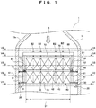
- the exhaust gas treatment device 1 includes a vessel body 10, a holding part 20, a downstream-side grid 30, a catalyst unit 40, a first seal plate 51, a second seal plate 52, a plurality of first cylinders 61, a plurality of second cylinders 62, an upstream-side grid 70, and a grid retainer 80.
- the vessel body 10 forms a gas passage R for flow of exhaust gas emitted from a ship or the like.
- the exhaust gas treatment device 1 is a so-called vertical exhaust-gas treatment device with a vertical gas passage R.
- the vessel body 10 is, for example, cylindrical in shape and contains the holding part 20 provided along the inner periphery of the vessel body 10.
- the holding part 20 is, for example, a thick metallic ring that is circumferentially welded to the interior of the vessel body 10.
- a cap 10a is provided upstream of the vessel body 10 in the gas passage R.
- the cap 10a has the same diameter as the vessel body 10 at the lower end of the cap 10a and tapers toward the upstream side.
- the downstream-side grid 30 has a placement area 31, which is provided for placing the catalyst unit 40, on an upper end face S1.
- the downstream-side grid 30 includes a plurality of bars 33 that are longitudinally, laterally, and diagonally combined in a grid-like fashion.
- the bars 33 form the placement area 31.
- Some of the bars 33 extend out of the placement area 31.
- the ends of the bars 33 extending out of the placement area 31 are welded onto the holding part 20 provided in the vessel body 10.
- the catalyst unit 40 includes a plurality of tubular cases 41 shaped like square poles, a catalyst 42 (see FIG. 3 ) contained in the tubular cases 41, and cylindrical attachments 43 (see FIG. 4 ) holding the ends of the tubular cases 41.
- the catalyst 42 for denitration contains a reducer, e.g., ammonia that reacts with NOx contained in exhaust gas.
- the catalyst 42 has a corrugated structure including a plurality of parallel plates and corrugated plates provided between the plates in horizontal cross section.
- the tubular case 41 has a body 41a and a projecting portion 41b that projects from the body 41a toward the downstream-side grid 30 (see FIGS.
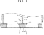
- an elastic seal member 32 is provided between the body 41a and the downstream-side grid 30.
- the elastic seal member 32 is bonded at least over the placement area 31 (see FIGS. 1 and 2 ) on the upper end face S1 of the downstream-side grid 30, more specifically, between the upper end face S1 of the downstream-side grid 30 and an end face S2 of the tubular case 41.
- an elastic member 72 (see FIG.
- the tubular cases 41 are disposed between the downstream-side grid 30 and the upstream-side grid 70.
- the tubular cases 41 are vertically stacked via the attachment 43, forming the two-stage configuration of the catalyst unit 40.
- the attachment 43 includes the body part 43a having the same external dimension as the tubular case 41 and two projecting portions 43b and 43c smaller than the external dimension.
- the projecting portion 43b projects upward from the body part 43a, whereas the projecting portion 43c projects downward from the body part 43a.
- the projecting portions 43b and 43c are each fit into the body 41a of the tubular case 41.
- the attachment 43 is not filled with the catalyst 42.
- the tubular case 41 has a tubular thickness T1 smaller than a tubular thickness T2 of the body part 43a of the attachment 43. This configuration reduces the weight of the tubular case 41 to be filled with the catalyst 42, facilitating handling of the tubular case 41 so that the tubular case 41 is easily moved by man power to be placed into the downstream-side grid 30.
- the first seal plate 51 is a circular plate member, from which the same flat shape as the placement area 31 is cut.
- the outside diameter of the first seal plate 51 is substantially equal to the inside diameter of the vessel body 10 and extends out of the upper end face S1 of the downstream-side grid 30.
- the outer circumference of the first seal plate 51 is welded to the inside of the vessel body 10.
- the first seal plate 51 is laid outside the placement area 31 of the downstream-side grid 30 on the upper end face S1.
- the first seal plate 51 in this state is welded to the downstream-side grid 30.
- the first cylinders 61 are raised on the first seal plate 51.
- the first cylinders 61 in this state are welded to the first seal plate 51.
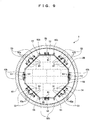
- the first cylinders 61 are, for example, rod members that are circular in cross section and are dispersed along the inner circumference of the vessel body 10.
- the second seal plate 52 is laid on the upper ends of the first cylinders 61. The second seal plate 52 in this state is welded to the first cylinders 61.
- recessed portions having shapes identical to the first cylinders 61 in cross section may be formed on the first seal plate 51 and the second seal plate 52 and then the first cylinders 61 may be fit into the recessed portions.
- the second seal plate 52 has the same shape as the first seal plate 51.
- the outer circumference of the second seal plate 52 is also welded to the inside of the vessel body 10.
- a plurality of angles 53 are fixed onto the second seal plate 52 so as to be dispersed along the circumferential direction.
- the angles 53 each include a bottom plate 53a and a side plate 53b.
- the bottom plate 53a is welded to the second seal plate 52.
- the side plate 53b is formed perpendicularly to the bottom plate 53a and has a through hole for a bolt B1.
- a retainer plate 54 is attached to a tip end of the bolt B1.
- the bolt B1 and a nut N1 are fastened so as to press the attachment 43 of the catalyst unit 40 from the outer circumferential side of the catalyst unit 40 via the retainer plate 54. This fixes the catalyst unit 40 in a direction (horizontal direction) perpendicular to the direction of the gas passage R (see FIG. 1 ).
- a seal member 55 is provided between the retainer plate 54 and the attachment 43.
- the seal member 55 is, for example, a metallic L-shaped member that includes a bottom plate 55a and a side plate 55b. As shown in FIG. 6 , the seal member 55 is provided over the outer circumference of the catalyst unit 40.
- the bottom plate 55a is brought into contact with the second seal plate 52 by its own weight.
- the side plate 55b is brought into contact with the attachment 43 by a press from the retainer plate 54.
- the seal member 55 comes into contact with both of the second seal plate 52 and the catalyst unit 40, thereby sealing a gap between the second seal plate 52 and the catalyst unit 40.
- the second cylinders 62 are raised on the second seal plate 52.
- the second cylinders 62 in this state are welded to the second seal plate 52.
- the second cylinders 62 include second cylinders 62a and second cylinders 62b.
- the second cylinder 62a includes a plate body 62aa and a plate support 62ab. In order to prevent the inclination of the body 62aa, the support 62ab is mounted perpendicularly to the body 62aa. As shown in FIGS.
- the second cylinder 62b includes a plate support 62bb mounted perpendicularly to a plate body 62ba.
- a plate 62bc is mounted in the horizontal direction perpendicular to the body 62ba.
- the upstream-side grid 70 is provided on the opposite side of the catalyst unit 40 from the downstream-side grid 30, that is, on the catalyst unit 40.
- the upstream-side grid 70 includes a plurality of bars 71 that are longitudinally, laterally, and diagonally combined in a grid-like fashion.
- the upstream-side grid 70 includes a plurality of plates 73 that are provided on the bars 71 or the intersections of the bars 71.
- the grid retainer 80 is further provided on the upstream-side grid 70.
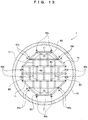
- the grid retainer 80 includes, as shown in FIG. 14 , two main bars 81 crossing each other at right angles at the center of the vessel body 10, and branches 82 from the two main bars 81.
- the main bar 81 is supported with one end and the other end held by the pair of second cylinders 62a.
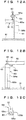
- FIGS. 11A and 11B one end of the main bar 81 and the bodies 62aa of the pair of second cylinders 62a are fastened with the bolt B4 and the nut N4.
- the branch 82 has one end supported by the second cylinder 62b. Specifically, as shown in FIG.
- one end of the branch 82 is placed on the horizontal plate 62bc of the second cylinder 62b, and the branch 82 and the plate 62bc are fastened with a bolt B5 and a nut N5.
- the grid retainer 80 is fixed by the second cylinders 62a and 62b.
- the main bars 81 of the grid retainer 80 shown in FIG. 14 are each provided with a plurality of vertical inner screws.
- the horizontal plates 73 of the upstream-side grid 70 in FIGS. 11B and 13 are pressed from above by bolts B2 through the inner screws.
- the plate 62bc of the second cylinder 62b is also provided with vertical inner screws.
- the plates 73 of the upstream-side grid 70 in FIGS. 12A and 13 are pressed from above by bolts B3 through the inner screws.
- the catalyst unit 40 is interposed between the downstream-side grid 30 and the upstream-side grid 70 in the direction of the gas passage R, and the elastic seal member 32 is pressed to be elastically deformed as shown in FIG. 6 .
- the elastic seal member 32 is elastically deformed so as to seal a gap between the downstream-side grid 30 and the catalyst unit 40.
- the elastic member 72 is also pressed to be elastically deformed.
- the elastic seal member 32 is provided between the body 41a of the tubular case 41 and the downstream-side grid 30, and the elastic member 72 is provided between the body 41a of the tubular case 41 and the upstream-side grid 70.
- the elastic seal member 32 and the elastic member 72 are pressed to be elastically deformed in the flowing direction of exhaust gas. This can improve the gas sealing performance of the exhaust gas treatment device 1. The detail will be discussed below.
- the elastic member is not used between the tubular case and the grids and thus the rolling of a ship or the vibrations of an engine may cause a gap between the grids and the catalyst unit. This may deteriorate the gas sealing performance of the exhaust gas treatment device.
- the elastic seal member 32 and the elastic member 72 are elastically deformed, so that the elastic seal member 32 seals a gap between the downstream-side grid 30 and the catalyst unit 40 while absorbing the rolling of a ship and the vibrations of an engine. This can seal gas in the catalyst unit 40.
- the catalyst unit 40 is pressed by the bolt B1 from the outer circumferential side so as to be fixed in a direction (horizontal direction) perpendicular to the direction of the gas passage R.
- This can suppress the occurrence of a gap between the downstream-side grid and the catalyst case due to the rolling of a ship or the vibrations of an engine, thereby improving the gas sealing performance of the exhaust gas treatment device 1.
- the bolt B1 horizontally fixing the catalyst unit 40 presses the body 43a (see FIG. 10 ) of the attachment 43 of the catalyst unit 40.
- the tubular case 41 may be pressed to fix the catalyst unit 40 perpendicularly to the gas passage R.
- the tubular case 41 is filled with the catalyst 42 and has the small thickness T1 for ease of handling. Thus, a large force applied to the tubular case 41 may considerably deform the tubular case 41 so as to damage the catalyst 42.
- the tubular thickness T2 of the body part 43a of the attachment 43 is larger than the tubular thickness T1 of the tubular case 41, so that the body 43a of the attachment 43 is not easily deformed by a certain force. Furthermore, the attachment 43 is not filled with the catalyst 42 and thus the catalyst 42 is not damaged even if the body 43a of the attachment 43 is deformed to some extent. As shown in FIGS. 4 and 7 , the attachment 43 is configured such that the projecting portions 43b and 43c are each fit into the body 41a of the tubular case 41. Thus, even when the attachment 43 is pressed, a force is not applied to the tubular case 41. With this configuration, the catalyst unit 40 can be more firmly fixed by pressing the body 43a of the attachment 43.
- the seal member 55 is provided between the retainer plate 54 and the attachment 43, sealing a gap between the second seal plate 52 and the catalyst unit 40.
- the elastic seal member 32 seals gas on the downstream-side grid 30 and the seal member 55 seals gas on the second seal plate 52 disposed upstream of the downstream-side grid 30. This leads to two-step gas sealing, achieving an excellent gas sealing performance.
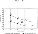
- FIG. 15 shows a comparison result between the exhaust gas treatment device according to the related art and the exhaust gas treatment device 1 according to the present embodiment.
- the exhaust gas treatment device according to the related art is not provided with the elastic seal member 32, the elastic member 72, and the seal member 55 unlike the structure of the exhaust gas treatment device 1 according to the present embodiment.
- the horizontal axis indicates an engine load.
- the vertical axis indicates the amount of ammonia (hereinafter, will be referred to as NH 3 slip) used as a reducing agent. Ammonia is detected downstream of the downstream-side grid 30 without reacting with NOx in exhaust gas.
- the NH 3 slip was reduced as compared with the structure of the related art regardless of an engine load.
- the reduction in NH 3 slip means that the amount of NH 3 reacting with NOx increases so as to improve the gas sealing performance of the exhaust gas treatment device.
- Examples of the elastic seal member 32 and the elastic member 72 include a gasket having heat resistance up to, for example, 800°C.
- the gasket is formed by soaking, into a heat-resistant material, a woven fabric of metal (stainless steel) wires used as the warp and metal (stainless steel) wire ceramic yarn used as the weft, and then performing endless machining on the woven fabric.
- the elastic seal member 32 and the elastic member 72 may be shaped with a thickness of, for example, 3 mm and a compressibility of 58% under a pressure of, for example, 5.9 MPa.
- the elastic seal member and the elastic member of the present invention are not limited to the specific conditions.
- the inside of the vessel body 10 reaches a high temperature and thus the elastic seal member and the elastic member preferably have heat resistance of, for example, at least 500°C.
- the elastic seal member 32 is provided between the tubular case 41 and the downstream-side grid 30, and the elastic member 72 is provided between the tubular case 41 and the upstream-side grid 70.
- the present invention is not limited to this configuration. Specifically, the gas sealing performance of the exhaust gas treatment device can be improved only by the elastic seal member 32 provided between the tubular case 41 and the downstream-side grid 30. If the elastic member 72 is provided in addition to the elastic seal member 32, the effect of absorbing the rolling of a ship or the like and the vibrations of an engine can be improved.
- the catalyst unit 40 includes the tubular cases 41 disposed in two stages.
- the present invention is not limited to this configuration.
- the catalyst unit 40 may have a single stage or three or more stages. If the catalyst unit 40 has multiple stages, in order to improve the gas sealing performance, it is preferable that the seal plates and the cylinders are alternately disposed as many as the number of stages of the catalyst unit 40 and the attachment 43 is provided between the tubular cases 41 so as to be pressed from the outer circumferential side.
- the catalyst unit 40 is pressed and fixed with the bolts B1, B2, and B3.
- the present invention is not limited to this configuration and other retainers may be used.
- the catalyst unit 40 can be fixed perpendicularly to the gas passage R also by disposing a retainer, e.g., a spring between the angle 53 and the attachment 43.
- the catalyst unit 40 can be fixed in the direction of the gas passage R by disposing a retainer between the grid retainer 80 and the upstream-side grid 70.
- the elastic seal member 32 and the seal member 55 are configured for gas sealing in two steps.
- the present invention is not limited to this configuration. Specifically, even if gas is sealed in the vessel body 10 only by the elastic seal member 32 without the seal member 55, the gas sealing performance can be improved as compared with the configuration of the exhaust gas treatment device not provided with the elastic seal member 32 or the seal member 55 according to the related art.
- an exhaust gas treatment device according to a second embodiment of the present invention, only differences from the exhaust gas treatment device 1 according to the first embodiment will be described below.
- the attachment 43 is provided between the tubular cases 41.
- an exhaust gas treatment device 2 according to the second embodiment is configured such that attachments 43 are provided between a downstream-side grid 30 and tubular cases 41 and between an upstream-side grid 70 and tubular cases 41 in addition to attachments 43 provided between the tubular cases 41.
- the attachments 43 are disposed in three stages.
- the tubular case 41 only includes a body 41a without a projecting portion unlike in the configuration of the first embodiment.
- the attachment 43 of the first stage from the downstream side of a gas passage R has a downward projecting portion 43c fit into the downstream-side grid 30 and an upward projecting portion 43b fit into the tubular case 41.
- the attachment 43 of the second stage has projecting portions 43b and 43c fit into the respective tubular cases 41.
- the attachment 43 of the third stage has an upward projecting portion 43b fit into the upstream-side grid 70 and a downward projecting portion 43c fit into the tubular case 41.
- the bodies 43a of the attachments 43 are pressed from the outer circumferential side of the catalyst unit 40.
- a specific configuration for pressing the body 43a is identical to that of the first embodiment shown in FIG. 10 and thus the explanation thereof is omitted.
- the attachments 43 in three stages are each pressed in the horizontal direction from the outer circumferential side of the catalyst unit 40.
- the catalyst unit 40 can be more firmly fixed than in the first embodiment in which the attachments 43 in the single stage are pressed from the outer circumferential side.
- the inclination of the tubular case 41 can be suppressed.
- the tubular cases 41 may be attached while the body of a ship is inclined by 20° or more.
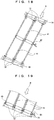
- the tubular cases 41 may be fit into the downstream-side grid 30 may be inclined as shown in FIG. 18 .
- elastic seal members 32 cannot be evenly pressed, thereby deteriorating the gas sealing performance of the exhaust gas treatment device.
- the attachments 43 are provided between the tubular cases 41 and the downstream-side grid 30, the attachments 43 being fit into the downstream-side grid 30 are hardly displaced as shown in FIG. 19 while the body of a ship is inclined by about 20° from the horizontal direction. This is because the attachment 43 is lower than the tubular case 41 and the center of gravity of the attachment 43 is close to the downstream-side grid 30.
- the tubular case 41 is fit to the attachment 43 with a minimum clearance. Since a displacement of the tubular case 41 can be suppressed, the elastic seal member 32 can be evenly pressed, thereby improving the gas sealing performance of the exhaust gas treatment device. This effect can be obtained if the attachments 43 are provided at least between the downstream-side grid 30 and the tubular cases 41. In other words, the attachments 43 may not be provided between the upstream-side grid 70 and the tubular cases 41.
- the tubular case 41 may only have the body 41a without a projecting portion 41b.
- the tubular cases 41 in the first and third stages have the projecting portions 41b but the tubular cases 41 in the second stage interposed between the attachments 43 do not have any projecting portions.
- the tubular cases 41 in the first to third stages only include the bodies 41a, thereby reducing the number of parts.
- the exhaust gas treatment devices 1 and 2 according to the first and second embodiments are so-called vertical exhaust-gas treatment devices.
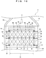
- the exhaust gas treatment device 3 according to the third embodiment is a so-called horizontal exhaust gas treatment device with a horizontal gas passage R.
- the basic configuration of the exhaust gas treatment device 3 is identical to the laid vertical exhaust gas treatment device 1.
- the third embodiment is different from the first embodiment as follows:
- the exhaust gas treatment device 3 is not provided with the first and second cylinders described in the first embodiment.
- a plurality of support columns 63 that support a catalyst unit 40 from below are provided instead of the first and second cylinders.
- a grid retainer 80 (see FIG. 24) is attached to, for example, the interior of a vessel body 10.
- the seal member 55 is not provided under the catalyst unit 40 but is provided only on the top and the side of the catalyst unit 40.
- each stage of the tubular cases 41 is pressed in the direction of the gas passage R.
- the tubular cases 41 in the first stage are pressed with an intermediate pressing tool 90 from the upstream side of the tubular cases 41 fit into a downstream-side grid 30.
- the intermediate pressing tool 90 includes, as shown in FIG. 21 , two vertical bars 91, four horizontal bars 92 including two horizontal bars on the right and two horizontal bars on the left, and long plates 93 extending across the two vertical bars 91 or the two horizontal bars 92.
- the vertical bars 91 are each attached to the inner circumference of a vessel body 10. Specifically, as shown in FIGS. 22A and 22B , one end of the vertical bar 91 is fastened with a bolt B6 and a nut N6 while being held by a pair of projecting plates 11 provided on the inner circumference of the vessel body 10.
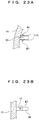
- the horizontal bar 92 has one end attached to the inner circumference of the vessel body 10 and the other end attached to the vertical bar 91. Specifically, as shown in FIGS. 23A and 23B , one end of the horizontal bar 92 is fastened with a bolt B7 and a nut N7 while being held by a pair of projecting plates 12 provided on the inner circumference of the vessel body 10. The other end of the horizontal bar 92 is fastened with a bolt and a nut while being held by projecting plates provided on the right or left side of the vertical bar 91.
- the vertical bar 91 and the horizontal bar 92 are each provided with horizontal inner screws. As shown in FIGS. 20 and 21 , bolts B9 are inserted into the inner screws.
- the long plate 93 is fixed to one end of the bolt B9.
- the long plates 93 are caused to press the tubular cases 41 in the direction of the gas passage R by adjusting the bolts B9.
- an elastic seal member 32 interposed between the tubular case 41 and the downstream-side grid 30 is pressed in the direction of the gas passage R, thereby uniformly placing the tubular cases 41 in the first stage in the horizontal direction.
- the intermediate pressing tool 90 is removed, the attachments 43 are disposed upstream of the tubular cases 41 in the first stage, and the tubular cases 41 in the second stage are disposed upstream of the attachments 43.
- an upstream-side grid 70 is provided upstream of the tubular cases 41 in the second stage so as to be pressed by a grid retainer 80 as in the first and second embodiments.
- an elastic member 72 interposed between the tubular cases 41 and the upstream-side grid 70 is pressed in the direction of the gas passage R.
- a specific method of attaching the grid retainer 80 to the interior of the vessel body 10 is similar to the method of attaching the intermediate pressing tool 90 to the interior of the vessel body 10 as shown in FIGS. 22A, 22B , 23A, and 23B , for example. Thus, the detailed explanation thereof is omitted.
- the intermediate pressing tool 90 is configured to press each stage of the tubular cases 41 in the direction of the gas passage R. This can uniformly place the tubular cases 41 in the horizontal direction.
- the elastic seal member 32 can seal gas in the catalyst unit 40 while the elastic seal members 32 and the elastic member 72 absorb the rolling of a ship and the vibrations of an engine.
- the exhaust gas treatment devices 1, 2, and 3 according to the first, second, and third embodiments are used for exhaust gas treatment in ships.
- the present invention is not always used for this purpose.
- the present invention is not limited to ships.
- the present invention is also applicable to a vehicle with involving rolling, engines and requiring exhaust gas treatment or the like.
Landscapes
- Chemical & Material Sciences (AREA)
- Engineering & Computer Science (AREA)
- Chemical Kinetics & Catalysis (AREA)
- Combustion & Propulsion (AREA)
- Health & Medical Sciences (AREA)
- Mechanical Engineering (AREA)
- General Engineering & Computer Science (AREA)
- Toxicology (AREA)
- Biomedical Technology (AREA)
- Environmental & Geological Engineering (AREA)
- Analytical Chemistry (AREA)
- General Chemical & Material Sciences (AREA)
- Oil, Petroleum & Natural Gas (AREA)
- Ocean & Marine Engineering (AREA)
- Exhaust Gas After Treatment (AREA)
- Exhaust Gas Treatment By Means Of Catalyst (AREA)
Applications Claiming Priority (2)
| Application Number | Priority Date | Filing Date | Title |
|---|---|---|---|
| JP2016108033A JP6703899B2 (ja) | 2016-05-31 | 2016-05-31 | 排ガス処理装置 |
| PCT/JP2017/017137 WO2017208722A1 (fr) | 2016-05-31 | 2017-05-01 | Dispositif de traitement de gaz d'échappement |
Publications (3)
| Publication Number | Publication Date |
|---|---|
| EP3467280A1 true EP3467280A1 (fr) | 2019-04-10 |
| EP3467280A4 EP3467280A4 (fr) | 2019-11-20 |
| EP3467280B1 EP3467280B1 (fr) | 2021-01-20 |
Family
ID=60479575
Family Applications (1)
| Application Number | Title | Priority Date | Filing Date |
|---|---|---|---|
| EP17806281.6A Not-in-force EP3467280B1 (fr) | 2016-05-31 | 2017-05-01 | Dispositif de traitement de gaz d'échappement |
Country Status (6)
| Country | Link |
|---|---|
| EP (1) | EP3467280B1 (fr) |
| JP (1) | JP6703899B2 (fr) |
| KR (1) | KR102286592B1 (fr) |
| CN (1) | CN109196198B (fr) |
| DK (1) | DK3467280T3 (fr) |
| WO (1) | WO2017208722A1 (fr) |
Cited By (1)
| Publication number | Priority date | Publication date | Assignee | Title |
|---|---|---|---|---|
| US11413599B2 (en) | 2018-07-13 | 2022-08-16 | Mitsubishi Heavy Industries Engineering, Ltd. | Catalytic reactor |
Families Citing this family (1)
| Publication number | Priority date | Publication date | Assignee | Title |
|---|---|---|---|---|
| JP7145668B2 (ja) * | 2018-07-13 | 2022-10-03 | 三菱重工エンジニアリング株式会社 | 触媒ユニットの着脱方法及び触媒反応器 |
Family Cites Families (18)
| Publication number | Priority date | Publication date | Assignee | Title |
|---|---|---|---|---|
| DE2220921C2 (de) * | 1972-04-28 | 1974-05-30 | Zeuna-Staerker Kg, 8900 Augsburg | Vorrichtung zur katalytischen reinigung der auspuffgase von brennkraftmaschinen |
| DE2216772A1 (de) * | 1972-04-07 | 1973-10-18 | Kali Chemie Ag | Elastische halterung fuer keramische monolithische katalysatorkoerper |
| JPS5925857B2 (ja) * | 1981-11-18 | 1984-06-21 | 中央発條株式会社 | ハニカム触媒体カセット成形方法 |
| JPS61265319A (ja) * | 1985-05-20 | 1986-11-25 | Honda Motor Co Ltd | 触媒コンバ−タ |
| JPS62294711A (ja) * | 1986-06-12 | 1987-12-22 | Nippon Soken Inc | 触媒コンバ−タ |
| JPS6390612A (ja) * | 1986-10-02 | 1988-04-21 | Mazda Motor Corp | 触媒コンバ−タ |
| JPH06264734A (ja) * | 1993-03-11 | 1994-09-20 | Calsonic Corp | セラミックス製触媒コンバータおよびその製造方法 |
| JP3113930B2 (ja) * | 1993-03-19 | 2000-12-04 | 日立造船株式会社 | モジュール化触媒 |
| JPH10103048A (ja) * | 1996-10-01 | 1998-04-21 | Hitachi Zosen Corp | 触媒エレメント |
| JPH1133409A (ja) * | 1997-07-23 | 1999-02-09 | Hitachi Zosen Corp | モジュール化触媒 |
| JP3757305B2 (ja) * | 1997-11-14 | 2006-03-22 | 日立造船株式会社 | モジュール化触媒 |
| JP5511865B2 (ja) * | 2012-02-13 | 2014-06-04 | 日立造船株式会社 | ディーゼルエンジン用排ガス脱硝装置 |
| JP6228727B2 (ja) * | 2012-02-22 | 2017-11-08 | 日立造船株式会社 | 触媒担持ハニカム構造体を具備する処理装置、およびその製造方法 |
| JP5295403B2 (ja) * | 2012-03-02 | 2013-09-18 | 日立造船株式会社 | 船舶用排ガス脱硝反応容器および排ガス脱硝設備 |
| KR101423578B1 (ko) * | 2012-11-27 | 2014-07-28 | 주식회사 파나시아 | 부피를 최소화하는 구조를 갖는 scr반응기 |
| JP5965857B2 (ja) * | 2013-03-27 | 2016-08-10 | ヤンマー株式会社 | 排気浄化装置 |
| DE102015004006B4 (de) * | 2015-03-30 | 2026-02-19 | Andreas Döring | Katalysatoreinheit und Abgaskatalysator |
| WO2016182806A1 (fr) * | 2015-05-08 | 2016-11-17 | Corning Incorporated | Boîtier, article de traitement de courant de fluide, système d'échappement et leurs procédés de fabrication |
-
2016
- 2016-05-31 JP JP2016108033A patent/JP6703899B2/ja active Active
-
2017
- 2017-05-01 DK DK17806281.6T patent/DK3467280T3/da active
- 2017-05-01 CN CN201780033529.5A patent/CN109196198B/zh active Active
- 2017-05-01 EP EP17806281.6A patent/EP3467280B1/fr not_active Not-in-force
- 2017-05-01 WO PCT/JP2017/017137 patent/WO2017208722A1/fr not_active Ceased
- 2017-05-01 KR KR1020187034985A patent/KR102286592B1/ko active Active
Cited By (1)
| Publication number | Priority date | Publication date | Assignee | Title |
|---|---|---|---|---|
| US11413599B2 (en) | 2018-07-13 | 2022-08-16 | Mitsubishi Heavy Industries Engineering, Ltd. | Catalytic reactor |
Also Published As
| Publication number | Publication date |
|---|---|
| JP2017214848A (ja) | 2017-12-07 |
| KR20190015279A (ko) | 2019-02-13 |
| EP3467280A4 (fr) | 2019-11-20 |
| DK3467280T3 (da) | 2021-04-19 |
| CN109196198B (zh) | 2021-02-12 |
| EP3467280B1 (fr) | 2021-01-20 |
| JP6703899B2 (ja) | 2020-06-03 |
| WO2017208722A1 (fr) | 2017-12-07 |
| KR102286592B1 (ko) | 2021-08-04 |
| CN109196198A (zh) | 2019-01-11 |
Similar Documents
| Publication | Publication Date | Title |
|---|---|---|
| US10422268B2 (en) | Mounting interface for exhaust gas treatment assembly | |
| US10240692B2 (en) | Fastening-type pipe supporting apparatus for curved pipe | |
| US20160178090A1 (en) | Dual p-clamp assembly | |
| EP3467280A1 (fr) | Dispositif de traitement de gaz d'échappement | |
| JP5610463B2 (ja) | 排気ガス浄化装置、排気システム、及びクランプ接続構造 | |
| WO2017094657A1 (fr) | Réacteur de dénitration | |
| KR101943785B1 (ko) | 촉매 컨버터 유닛 및 배기가스 촉매 컨버터 | |
| JP6513592B2 (ja) | 触媒ユニットおよび排ガス触媒 | |
| US10017311B2 (en) | Honeycomb assembly and packaging system | |
| KR101371462B1 (ko) | 차량용 배기계의 가스켓 | |
| GB2560352A (en) | Aftertreatment canister mounting bracket | |
| US11655917B2 (en) | Pipe vibration-proof channel | |
| JP5988165B2 (ja) | 排気系部品への遮熱カバーの防振取り付け構造 | |
| EP3444458B1 (fr) | Procédé de fabrication de dispositif de traitement de gaz d'échappement | |
| US20150204375A1 (en) | Component connection comprising at least two cfc components | |
| KR102298871B1 (ko) | 와셔 및 이를 포함하는 체결 구조 | |
| JP2020045960A (ja) | 配管保護装置 | |
| JP4674055B2 (ja) | ガスケット | |
| JP7353463B2 (ja) | ボイラ装置およびボイラ炉壁の補強構造 | |
| US11982200B1 (en) | Structure with structural reinforcement patterns | |
| JP2007032605A (ja) | 金属ガスケット | |
| US11149613B2 (en) | Exhaust gas treatment article and methods of manufacturing same | |
| JP2021071050A (ja) | 排気浄化構造 | |
| KR101115304B1 (ko) | 완충기능이 있는 아일릿 금구 | |
| WO2023140167A1 (fr) | Dispositif de support de tuyau |
Legal Events
| Date | Code | Title | Description |
|---|---|---|---|
| STAA | Information on the status of an ep patent application or granted ep patent |
Free format text: STATUS: THE INTERNATIONAL PUBLICATION HAS BEEN MADE |
|
| PUAI | Public reference made under article 153(3) epc to a published international application that has entered the european phase |
Free format text: ORIGINAL CODE: 0009012 |
|
| STAA | Information on the status of an ep patent application or granted ep patent |
Free format text: STATUS: REQUEST FOR EXAMINATION WAS MADE |
|
| 17P | Request for examination filed |
Effective date: 20181219 |
|
| AK | Designated contracting states |
Kind code of ref document: A1 Designated state(s): AL AT BE BG CH CY CZ DE DK EE ES FI FR GB GR HR HU IE IS IT LI LT LU LV MC MK MT NL NO PL PT RO RS SE SI SK SM TR |
|
| AX | Request for extension of the european patent |
Extension state: BA ME |
|
| DAV | Request for validation of the european patent (deleted) | ||
| DAX | Request for extension of the european patent (deleted) | ||
| A4 | Supplementary search report drawn up and despatched |
Effective date: 20191022 |
|
| RIC1 | Information provided on ipc code assigned before grant |
Ipc: F01N 13/18 20100101ALI20191016BHEP Ipc: F01N 3/20 20060101ALI20191016BHEP Ipc: F01N 3/28 20060101AFI20191016BHEP Ipc: B01D 53/94 20060101ALI20191016BHEP Ipc: F01N 13/00 20100101ALI20191016BHEP |
|
| GRAP | Despatch of communication of intention to grant a patent |
Free format text: ORIGINAL CODE: EPIDOSNIGR1 |
|
| STAA | Information on the status of an ep patent application or granted ep patent |
Free format text: STATUS: GRANT OF PATENT IS INTENDED |
|
| INTG | Intention to grant announced |
Effective date: 20200918 |
|
| GRAS | Grant fee paid |
Free format text: ORIGINAL CODE: EPIDOSNIGR3 |
|
| GRAA | (expected) grant |
Free format text: ORIGINAL CODE: 0009210 |
|
| STAA | Information on the status of an ep patent application or granted ep patent |
Free format text: STATUS: THE PATENT HAS BEEN GRANTED |
|
| AK | Designated contracting states |
Kind code of ref document: B1 Designated state(s): AL AT BE BG CH CY CZ DE DK EE ES FI FR GB GR HR HU IE IS IT LI LT LU LV MC MK MT NL NO PL PT RO RS SE SI SK SM TR |
|
| REG | Reference to a national code |
Ref country code: GB Ref legal event code: FG4D |
|
| REG | Reference to a national code |
Ref country code: CH Ref legal event code: NV Representative=s name: BOVARD AG PATENT- UND MARKENANWAELTE, CH Ref country code: CH Ref legal event code: EP |
|
| REG | Reference to a national code |
Ref country code: DE Ref legal event code: R096 Ref document number: 602017031766 Country of ref document: DE |
|
| REG | Reference to a national code |
Ref country code: AT Ref legal event code: REF Ref document number: 1356587 Country of ref document: AT Kind code of ref document: T Effective date: 20210215 |
|
| REG | Reference to a national code |
Ref country code: IE Ref legal event code: FG4D |
|
| REG | Reference to a national code |
Ref country code: DK Ref legal event code: T3 Effective date: 20210412 |
|
| REG | Reference to a national code |
Ref country code: NL Ref legal event code: MP Effective date: 20210120 |
|
| REG | Reference to a national code |
Ref country code: LT Ref legal event code: MG9D |
|
| REG | Reference to a national code |
Ref country code: AT Ref legal event code: MK05 Ref document number: 1356587 Country of ref document: AT Kind code of ref document: T Effective date: 20210120 |
|
| PG25 | Lapsed in a contracting state [announced via postgrant information from national office to epo] |
Ref country code: FI Free format text: LAPSE BECAUSE OF FAILURE TO SUBMIT A TRANSLATION OF THE DESCRIPTION OR TO PAY THE FEE WITHIN THE PRESCRIBED TIME-LIMIT Effective date: 20210120 Ref country code: HR Free format text: LAPSE BECAUSE OF FAILURE TO SUBMIT A TRANSLATION OF THE DESCRIPTION OR TO PAY THE FEE WITHIN THE PRESCRIBED TIME-LIMIT Effective date: 20210120 Ref country code: GR Free format text: LAPSE BECAUSE OF FAILURE TO SUBMIT A TRANSLATION OF THE DESCRIPTION OR TO PAY THE FEE WITHIN THE PRESCRIBED TIME-LIMIT Effective date: 20210421 Ref country code: PT Free format text: LAPSE BECAUSE OF FAILURE TO SUBMIT A TRANSLATION OF THE DESCRIPTION OR TO PAY THE FEE WITHIN THE PRESCRIBED TIME-LIMIT Effective date: 20210520 Ref country code: NO Free format text: LAPSE BECAUSE OF FAILURE TO SUBMIT A TRANSLATION OF THE DESCRIPTION OR TO PAY THE FEE WITHIN THE PRESCRIBED TIME-LIMIT Effective date: 20210420 Ref country code: LT Free format text: LAPSE BECAUSE OF FAILURE TO SUBMIT A TRANSLATION OF THE DESCRIPTION OR TO PAY THE FEE WITHIN THE PRESCRIBED TIME-LIMIT Effective date: 20210120 Ref country code: BG Free format text: LAPSE BECAUSE OF FAILURE TO SUBMIT A TRANSLATION OF THE DESCRIPTION OR TO PAY THE FEE WITHIN THE PRESCRIBED TIME-LIMIT Effective date: 20210420 |
|
| PG25 | Lapsed in a contracting state [announced via postgrant information from national office to epo] |
Ref country code: AT Free format text: LAPSE BECAUSE OF FAILURE TO SUBMIT A TRANSLATION OF THE DESCRIPTION OR TO PAY THE FEE WITHIN THE PRESCRIBED TIME-LIMIT Effective date: 20210120 Ref country code: RS Free format text: LAPSE BECAUSE OF FAILURE TO SUBMIT A TRANSLATION OF THE DESCRIPTION OR TO PAY THE FEE WITHIN THE PRESCRIBED TIME-LIMIT Effective date: 20210120 Ref country code: LV Free format text: LAPSE BECAUSE OF FAILURE TO SUBMIT A TRANSLATION OF THE DESCRIPTION OR TO PAY THE FEE WITHIN THE PRESCRIBED TIME-LIMIT Effective date: 20210120 Ref country code: PL Free format text: LAPSE BECAUSE OF FAILURE TO SUBMIT A TRANSLATION OF THE DESCRIPTION OR TO PAY THE FEE WITHIN THE PRESCRIBED TIME-LIMIT Effective date: 20210120 Ref country code: SE Free format text: LAPSE BECAUSE OF FAILURE TO SUBMIT A TRANSLATION OF THE DESCRIPTION OR TO PAY THE FEE WITHIN THE PRESCRIBED TIME-LIMIT Effective date: 20210120 |
|
| PG25 | Lapsed in a contracting state [announced via postgrant information from national office to epo] |
Ref country code: IS Free format text: LAPSE BECAUSE OF FAILURE TO SUBMIT A TRANSLATION OF THE DESCRIPTION OR TO PAY THE FEE WITHIN THE PRESCRIBED TIME-LIMIT Effective date: 20210520 |
|
| REG | Reference to a national code |
Ref country code: DE Ref legal event code: R097 Ref document number: 602017031766 Country of ref document: DE |
|
| PG25 | Lapsed in a contracting state [announced via postgrant information from national office to epo] |
Ref country code: SM Free format text: LAPSE BECAUSE OF FAILURE TO SUBMIT A TRANSLATION OF THE DESCRIPTION OR TO PAY THE FEE WITHIN THE PRESCRIBED TIME-LIMIT Effective date: 20210120 Ref country code: CZ Free format text: LAPSE BECAUSE OF FAILURE TO SUBMIT A TRANSLATION OF THE DESCRIPTION OR TO PAY THE FEE WITHIN THE PRESCRIBED TIME-LIMIT Effective date: 20210120 Ref country code: EE Free format text: LAPSE BECAUSE OF FAILURE TO SUBMIT A TRANSLATION OF THE DESCRIPTION OR TO PAY THE FEE WITHIN THE PRESCRIBED TIME-LIMIT Effective date: 20210120 |
|
| PLBE | No opposition filed within time limit |
Free format text: ORIGINAL CODE: 0009261 |
|
| STAA | Information on the status of an ep patent application or granted ep patent |
Free format text: STATUS: NO OPPOSITION FILED WITHIN TIME LIMIT |
|
| PG25 | Lapsed in a contracting state [announced via postgrant information from national office to epo] |
Ref country code: RO Free format text: LAPSE BECAUSE OF FAILURE TO SUBMIT A TRANSLATION OF THE DESCRIPTION OR TO PAY THE FEE WITHIN THE PRESCRIBED TIME-LIMIT Effective date: 20210120 Ref country code: SK Free format text: LAPSE BECAUSE OF FAILURE TO SUBMIT A TRANSLATION OF THE DESCRIPTION OR TO PAY THE FEE WITHIN THE PRESCRIBED TIME-LIMIT Effective date: 20210120 |
|
| 26N | No opposition filed |
Effective date: 20211021 |
|
| GBPC | Gb: european patent ceased through non-payment of renewal fee |
Effective date: 20210501 |
|
| PG25 | Lapsed in a contracting state [announced via postgrant information from national office to epo] |
Ref country code: LU Free format text: LAPSE BECAUSE OF NON-PAYMENT OF DUE FEES Effective date: 20210501 Ref country code: MC Free format text: LAPSE BECAUSE OF FAILURE TO SUBMIT A TRANSLATION OF THE DESCRIPTION OR TO PAY THE FEE WITHIN THE PRESCRIBED TIME-LIMIT Effective date: 20210120 Ref country code: AL Free format text: LAPSE BECAUSE OF FAILURE TO SUBMIT A TRANSLATION OF THE DESCRIPTION OR TO PAY THE FEE WITHIN THE PRESCRIBED TIME-LIMIT Effective date: 20210120 Ref country code: ES Free format text: LAPSE BECAUSE OF FAILURE TO SUBMIT A TRANSLATION OF THE DESCRIPTION OR TO PAY THE FEE WITHIN THE PRESCRIBED TIME-LIMIT Effective date: 20210120 |
|
| REG | Reference to a national code |
Ref country code: BE Ref legal event code: MM Effective date: 20210531 |
|
| PG25 | Lapsed in a contracting state [announced via postgrant information from national office to epo] |
Ref country code: SI Free format text: LAPSE BECAUSE OF FAILURE TO SUBMIT A TRANSLATION OF THE DESCRIPTION OR TO PAY THE FEE WITHIN THE PRESCRIBED TIME-LIMIT Effective date: 20210120 |
|
| PG25 | Lapsed in a contracting state [announced via postgrant information from national office to epo] |
Ref country code: IT Free format text: LAPSE BECAUSE OF FAILURE TO SUBMIT A TRANSLATION OF THE DESCRIPTION OR TO PAY THE FEE WITHIN THE PRESCRIBED TIME-LIMIT Effective date: 20210120 Ref country code: IE Free format text: LAPSE BECAUSE OF NON-PAYMENT OF DUE FEES Effective date: 20210501 Ref country code: GB Free format text: LAPSE BECAUSE OF NON-PAYMENT OF DUE FEES Effective date: 20210501 |
|
| PG25 | Lapsed in a contracting state [announced via postgrant information from national office to epo] |
Ref country code: IS Free format text: LAPSE BECAUSE OF FAILURE TO SUBMIT A TRANSLATION OF THE DESCRIPTION OR TO PAY THE FEE WITHIN THE PRESCRIBED TIME-LIMIT Effective date: 20210520 Ref country code: FR Free format text: LAPSE BECAUSE OF NON-PAYMENT OF DUE FEES Effective date: 20210531 |
|
| PG25 | Lapsed in a contracting state [announced via postgrant information from national office to epo] |
Ref country code: BE Free format text: LAPSE BECAUSE OF NON-PAYMENT OF DUE FEES Effective date: 20210531 |
|
| PGFP | Annual fee paid to national office [announced via postgrant information from national office to epo] |
Ref country code: DK Payment date: 20220510 Year of fee payment: 6 Ref country code: DE Payment date: 20220329 Year of fee payment: 6 |
|
| PGFP | Annual fee paid to national office [announced via postgrant information from national office to epo] |
Ref country code: CH Payment date: 20220421 Year of fee payment: 6 |
|
| P01 | Opt-out of the competence of the unified patent court (upc) registered |
Effective date: 20230509 |
|
| PG25 | Lapsed in a contracting state [announced via postgrant information from national office to epo] |
Ref country code: NL Free format text: LAPSE BECAUSE OF NON-PAYMENT OF DUE FEES Effective date: 20210120 Ref country code: CY Free format text: LAPSE BECAUSE OF FAILURE TO SUBMIT A TRANSLATION OF THE DESCRIPTION OR TO PAY THE FEE WITHIN THE PRESCRIBED TIME-LIMIT Effective date: 20210120 |
|
| PG25 | Lapsed in a contracting state [announced via postgrant information from national office to epo] |
Ref country code: HU Free format text: LAPSE BECAUSE OF FAILURE TO SUBMIT A TRANSLATION OF THE DESCRIPTION OR TO PAY THE FEE WITHIN THE PRESCRIBED TIME-LIMIT; INVALID AB INITIO Effective date: 20170501 |
|
| REG | Reference to a national code |
Ref country code: DE Ref legal event code: R119 Ref document number: 602017031766 Country of ref document: DE |
|
| REG | Reference to a national code |
Ref country code: CH Ref legal event code: PL |
|
| REG | Reference to a national code |
Ref country code: DK Ref legal event code: EBP Effective date: 20230531 |
|
| PG25 | Lapsed in a contracting state [announced via postgrant information from national office to epo] |
Ref country code: LI Free format text: LAPSE BECAUSE OF NON-PAYMENT OF DUE FEES Effective date: 20230531 Ref country code: CH Free format text: LAPSE BECAUSE OF NON-PAYMENT OF DUE FEES Effective date: 20230531 |
|
| PG25 | Lapsed in a contracting state [announced via postgrant information from national office to epo] |
Ref country code: MK Free format text: LAPSE BECAUSE OF FAILURE TO SUBMIT A TRANSLATION OF THE DESCRIPTION OR TO PAY THE FEE WITHIN THE PRESCRIBED TIME-LIMIT Effective date: 20210120 Ref country code: DK Free format text: LAPSE BECAUSE OF NON-PAYMENT OF DUE FEES Effective date: 20230531 Ref country code: DE Free format text: LAPSE BECAUSE OF NON-PAYMENT OF DUE FEES Effective date: 20231201 |
|
| PG25 | Lapsed in a contracting state [announced via postgrant information from national office to epo] |
Ref country code: TR Free format text: LAPSE BECAUSE OF FAILURE TO SUBMIT A TRANSLATION OF THE DESCRIPTION OR TO PAY THE FEE WITHIN THE PRESCRIBED TIME-LIMIT Effective date: 20210120 |
|
| PG25 | Lapsed in a contracting state [announced via postgrant information from national office to epo] |
Ref country code: MT Free format text: LAPSE BECAUSE OF FAILURE TO SUBMIT A TRANSLATION OF THE DESCRIPTION OR TO PAY THE FEE WITHIN THE PRESCRIBED TIME-LIMIT Effective date: 20210120 |