EP3467331A1 - Arbre de déconnexion pour générateur à entraînement intégré - Google Patents
Arbre de déconnexion pour générateur à entraînement intégré Download PDFInfo
- Publication number
- EP3467331A1 EP3467331A1 EP18196677.1A EP18196677A EP3467331A1 EP 3467331 A1 EP3467331 A1 EP 3467331A1 EP 18196677 A EP18196677 A EP 18196677A EP 3467331 A1 EP3467331 A1 EP 3467331A1
- Authority
- EP
- European Patent Office
- Prior art keywords
- cam
- shaft
- face
- disconnect shaft
- disconnect
- Prior art date
- Legal status (The legal status is an assumption and is not a legal conclusion. Google has not performed a legal analysis and makes no representation as to the accuracy of the status listed.)
- Granted
Links
Images


Classifications
-
- F—MECHANICAL ENGINEERING; LIGHTING; HEATING; WEAPONS; BLASTING
- F16—ENGINEERING ELEMENTS AND UNITS; GENERAL MEASURES FOR PRODUCING AND MAINTAINING EFFECTIVE FUNCTIONING OF MACHINES OR INSTALLATIONS; THERMAL INSULATION IN GENERAL
- F16D—COUPLINGS FOR TRANSMITTING ROTATION; CLUTCHES; BRAKES
- F16D1/00—Couplings for rigidly connecting two coaxial shafts or other movable machine elements
- F16D1/02—Couplings for rigidly connecting two coaxial shafts or other movable machine elements for connecting two abutting shafts or the like
- F16D1/04—Couplings for rigidly connecting two coaxial shafts or other movable machine elements for connecting two abutting shafts or the like with clamping hub; with hub and longitudinal key
-
- F—MECHANICAL ENGINEERING; LIGHTING; HEATING; WEAPONS; BLASTING
- F02—COMBUSTION ENGINES; HOT-GAS OR COMBUSTION-PRODUCT ENGINE PLANTS
- F02C—GAS-TURBINE PLANTS; AIR INTAKES FOR JET-PROPULSION PLANTS; CONTROLLING FUEL SUPPLY IN AIR-BREATHING JET-PROPULSION PLANTS
- F02C7/00—Features, components parts, details or accessories, not provided for in, or of interest apart form groups F02C1/00 - F02C6/00; Air intakes for jet-propulsion plants
- F02C7/32—Arrangement, mounting, or driving, of auxiliaries
-
- F—MECHANICAL ENGINEERING; LIGHTING; HEATING; WEAPONS; BLASTING
- F02—COMBUSTION ENGINES; HOT-GAS OR COMBUSTION-PRODUCT ENGINE PLANTS
- F02C—GAS-TURBINE PLANTS; AIR INTAKES FOR JET-PROPULSION PLANTS; CONTROLLING FUEL SUPPLY IN AIR-BREATHING JET-PROPULSION PLANTS
- F02C7/00—Features, components parts, details or accessories, not provided for in, or of interest apart form groups F02C1/00 - F02C6/00; Air intakes for jet-propulsion plants
- F02C7/36—Power transmission arrangements between the different shafts of the gas turbine plant, or between the gas-turbine plant and the power user
-
- F—MECHANICAL ENGINEERING; LIGHTING; HEATING; WEAPONS; BLASTING
- F16—ENGINEERING ELEMENTS AND UNITS; GENERAL MEASURES FOR PRODUCING AND MAINTAINING EFFECTIVE FUNCTIONING OF MACHINES OR INSTALLATIONS; THERMAL INSULATION IN GENERAL
- F16C—SHAFTS; FLEXIBLE SHAFTS; ELEMENTS OR CRANKSHAFT MECHANISMS; ROTARY BODIES OTHER THAN GEARING ELEMENTS; BEARINGS
- F16C3/00—Shafts; Axles; Cranks; Eccentrics
- F16C3/02—Shafts; Axles
-
- F—MECHANICAL ENGINEERING; LIGHTING; HEATING; WEAPONS; BLASTING
- F16—ENGINEERING ELEMENTS AND UNITS; GENERAL MEASURES FOR PRODUCING AND MAINTAINING EFFECTIVE FUNCTIONING OF MACHINES OR INSTALLATIONS; THERMAL INSULATION IN GENERAL
- F16D—COUPLINGS FOR TRANSMITTING ROTATION; CLUTCHES; BRAKES
- F16D11/00—Clutches in which the members have interengaging parts
- F16D11/02—Clutches in which the members have interengaging parts disengaged by a contact of a part mounted on the clutch with a stationarily-mounted member
- F16D11/04—Clutches in which the members have interengaging parts disengaged by a contact of a part mounted on the clutch with a stationarily-mounted member with clutching members movable only axially
-
- F—MECHANICAL ENGINEERING; LIGHTING; HEATING; WEAPONS; BLASTING
- F16—ENGINEERING ELEMENTS AND UNITS; GENERAL MEASURES FOR PRODUCING AND MAINTAINING EFFECTIVE FUNCTIONING OF MACHINES OR INSTALLATIONS; THERMAL INSULATION IN GENERAL
- F16D—COUPLINGS FOR TRANSMITTING ROTATION; CLUTCHES; BRAKES
- F16D11/00—Clutches in which the members have interengaging parts
- F16D11/14—Clutches in which the members have interengaging parts with clutching members movable only axially
-
- F—MECHANICAL ENGINEERING; LIGHTING; HEATING; WEAPONS; BLASTING
- F16—ENGINEERING ELEMENTS AND UNITS; GENERAL MEASURES FOR PRODUCING AND MAINTAINING EFFECTIVE FUNCTIONING OF MACHINES OR INSTALLATIONS; THERMAL INSULATION IN GENERAL
- F16H—GEARING
- F16H3/00—Toothed gearings for conveying rotary motion with variable gear ratio or for reversing rotary motion
- F16H3/44—Toothed gearings for conveying rotary motion with variable gear ratio or for reversing rotary motion using gears having orbital motion
- F16H3/72—Toothed gearings for conveying rotary motion with variable gear ratio or for reversing rotary motion using gears having orbital motion with a secondary drive, e.g. regulating motor, in order to vary speed continuously
- F16H3/727—Toothed gearings for conveying rotary motion with variable gear ratio or for reversing rotary motion using gears having orbital motion with a secondary drive, e.g. regulating motor, in order to vary speed continuously with at least two dynamo electric machines for creating an electric power path inside the gearing, e.g. using generator and motor for a variable power torque path
- F16H3/728—Toothed gearings for conveying rotary motion with variable gear ratio or for reversing rotary motion using gears having orbital motion with a secondary drive, e.g. regulating motor, in order to vary speed continuously with at least two dynamo electric machines for creating an electric power path inside the gearing, e.g. using generator and motor for a variable power torque path with means to change ratio in the mechanical gearing
-
- H—ELECTRICITY
- H02—GENERATION; CONVERSION OR DISTRIBUTION OF ELECTRIC POWER
- H02K—DYNAMO-ELECTRIC MACHINES
- H02K7/00—Arrangements for handling mechanical energy structurally associated with dynamo-electric machines, e.g. structural association with mechanical driving motors or auxiliary dynamo-electric machines
- H02K7/18—Structural association of electric generators with mechanical driving motors, e.g. with turbines
- H02K7/1807—Rotary generators
-
- F—MECHANICAL ENGINEERING; LIGHTING; HEATING; WEAPONS; BLASTING
- F16—ENGINEERING ELEMENTS AND UNITS; GENERAL MEASURES FOR PRODUCING AND MAINTAINING EFFECTIVE FUNCTIONING OF MACHINES OR INSTALLATIONS; THERMAL INSULATION IN GENERAL
- F16D—COUPLINGS FOR TRANSMITTING ROTATION; CLUTCHES; BRAKES
- F16D11/00—Clutches in which the members have interengaging parts
- F16D2011/008—Clutches in which the members have interengaging parts characterised by the form of the teeth forming the inter-engaging parts; Details of shape or structure of these teeth
-
- F—MECHANICAL ENGINEERING; LIGHTING; HEATING; WEAPONS; BLASTING
- F16—ENGINEERING ELEMENTS AND UNITS; GENERAL MEASURES FOR PRODUCING AND MAINTAINING EFFECTIVE FUNCTIONING OF MACHINES OR INSTALLATIONS; THERMAL INSULATION IN GENERAL
- F16D—COUPLINGS FOR TRANSMITTING ROTATION; CLUTCHES; BRAKES
- F16D23/00—Details of mechanically-actuated clutches not specific for one distinct type
- F16D23/12—Mechanical clutch-actuating mechanisms arranged outside the clutch as such
- F16D2023/123—Clutch actuation by cams, ramps or ball-screw mechanisms
-
- Y—GENERAL TAGGING OF NEW TECHNOLOGICAL DEVELOPMENTS; GENERAL TAGGING OF CROSS-SECTIONAL TECHNOLOGIES SPANNING OVER SEVERAL SECTIONS OF THE IPC; TECHNICAL SUBJECTS COVERED BY FORMER USPC CROSS-REFERENCE ART COLLECTIONS [XRACs] AND DIGESTS
- Y10—TECHNICAL SUBJECTS COVERED BY FORMER USPC
- Y10T—TECHNICAL SUBJECTS COVERED BY FORMER US CLASSIFICATION
- Y10T403/00—Joints and connections
- Y10T403/70—Interfitted members
- Y10T403/7045—Interdigitated ends
Definitions
- This application relates to a disconnect shaft for an integrated drive generator.
- Integrated drive generators are known and often utilized in aircraft.
- a gas turbine engine on the aircraft provides a drive input into a generator input shaft.
- the generator typically includes a disconnect shaft that can transmit the input into a gear differential.
- the gear differential selectively drives a main generator to provide electric power for various uses on the aircraft.
- the generated power be of a desired constant frequency.
- the speed from the input shaft will vary during operation of the gas turbine engine. This would result in variable frequency.
- Integrated drive generators are provided with speed trimming hydraulic units. Gears associated with the differential and, in particular, a ring gear portion, provide rotation from the differential back into the trimming unit. A carrier also rotates another portion of the trimming unit. The trimming unit is operable to result in the output speed of the differential being effectively constant, such that electric power of a desirable frequency is generated.
- the generator is mounted between two housing portions and a seal plate is mounted between the two housing portions.
- various accessory systems such as various pumps, are driven by the carrier of the differential through an accessory drive gear.
- the disconnect shaft is typically cammed to move axially away from the input shaft.
- a spring typically biases the disconnect shaft toward the input shaft.
- the disconnect shaft drives the carrier when in contact with the input shaft. As can be appreciated, the disconnect shaft faces challenges.
- a disconnect shaft for use in an integrated drive generator longitudinally extending between a first end and a second end having a plurality of gear teeth extending longitudinally from a first face disposed at the first end.
- a cam ledge is at an intermediate location between the first end and the second end.
- An annular cavity is defined between an inner surface of an inner bore of the disconnect shaft and an outer surface of a radially inner portion of the disconnect shaft.
- An integrated drive generator is also disclosed, as is a method of replacing a disconnect shaft in an integrated drive generator.
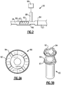
- FIG. 1 shows an integrated drive generator 20. As shown, housing portions 18 and 19 surround the integrated drive generator and a seal plate 17 sits between the housing portions 18 and 19.
- a gas turbine engine 22 may drive an input shaft 23 which selectively drives a disconnect assembly 26.
- the disconnect assembly 26 in turn, drives a carrier shaft 28, which drives a carrier in a gear differential 30.
- Gears 38 have a gear interface 42 with a first ring gear portion 40.
- Gears 36 have a gear interface 48 with a second ring gear portion 46.
- Ring gear portion 40 has a gear interface 50 with a main generator drive gear 52.
- drive gear 52 When drive gear 52 is driven to rotate, it rotates a rotor 56 associated with a stator 58 of the main generator as well as an exciter rotor 60. Electric power is generated for a use 62, as known.
- the frequency of the generated electric power be at a desired frequency.
- a gear 15 that is part of the carrier has a gear interface 16 with a gear 13 driving a shaft 14 also within the speed trimmer.
- the speed trimmer 66 includes a variable unit 72 and a fixed unit 76.
- the units 72 and 76 may each be provided with a plurality of pistons and a swash plate arrangement. If the input speed of the gear 13 is too high, the speed of the gear 52 will also be too high, and hence, the speed trimmer 66 acts to lower the speed of the trim gear 46 which will drop the speed of gear 52. On the other hand, if the input speed is too low, the speed trimmer will increase the trim gear speed and he speed seen by gear 52 will increase.
- variable unit 72 receives an input through gear 13 that is proportional to the speed of the input shaft 23.
- the variable unit 72 also receives a control input from a control monitoring the speed of the generator rotor 56.
- the position of the swash plate in the variable unit 72 is changed to in turn change the speed and direction of the fixed unit 76.
- the fixed unit 76 can change the speed, and direction of rotation of the shaft 70, and this then provides control back through the trim ring gear 46 to change the speed reaching the generator.
- the speed trimmer 66 results in the frequency generated by the generator being closer to constant, and at the desired frequency.
- a permanent magnet generator 32 rotates with the ring gear 40.
- An accessory drive shaft 29 rotates with the carrier shaft 28 and drives a plurality of accessory gears 31.
- the operation of the integrated drive generator 20 is generally as known in the art. A worker of ordinary skill would recognize that the desired frequency and speed at use 62 would dictate a number of design functions.
- Figure 2 schematically shows the disconnect assembly 26.
- the input shaft 23 contacts a gear interface 84 with a disconnect shaft 80.
- a spline connection 82 drives the carrier shaft 28.
- a spring 83 biases the disconnect shaft 80 towards engagement with the input shaft 23.
- a cam face on a cam ledge 86 on the disconnect shaft 80 receives an actuator 88 under the operation of a control 90.
- the actuator 88 can provide camming action along the cam face to move the disconnect shaft 80 to the left, in this figure, and against the force of the spring 83 to break the drive connection between the input shaft 23 and the disconnect shaft 80.
- This basic operation is known in current integrated drive generators.
- Figure 3A shows a front face of the disconnect shaft 80.
- a plurality of gear teeth 94 are positioned on a front face 92. There are four teeth in the disclosed embodiment.
- Figure 3B is a perspective view and shows the disconnect shaft 80, the front face 92, and the teeth 94. Also, a cam face 87 is shown on cam ledge 86.
- the front face 92 of the disconnect shaft 80 is spaced from an end 96 of an enlarged forward portion.
- a channel 98 is positioned between end 96 and the cam ledge 86.
- the cam face 87 has a changing profile across a circumferential dimension, such that the actuator 88 can cause the disconnect shaft 80 to move to the left against the force of a spring 106.
- the spring 106 sits between an end face of the carrier shaft 28 and a cavity 110.
- the carrier shaft 28 rides along spline teeth 104 inside the disconnect shaft to drive the carrier shaft when the disconnect shaft rotates.
- a rear end 102 of the disconnect shaft is also shown.
- Cavity 110 houses the spring 106.
- the cavity 110 is defined by a radially inner portion 111 spaced inwardly from a radially outer portion 113 and providing cavity 110 to receive a forward end 108 of the spring 106.
- the cavity 110 provides support for the end of the spring 106.
- Cavity 110 is shown spaced toward rear end 102 relative to cam ledge 86.
- An outer diameter d 1 is defined as a diameter to an outer peripheral surface of the front face 92.
- An inner diameter d 2 is defined to a radially inner surface 95 of a bore at the front face 92.
- a cam ledge distance d 3 is defined between the front face 92 and a beginning of the cam ledge 86.
- a diameter d 4 is defined to the outer periphery of the cam surface 87.
- An overall distance d 5 is defined between rear end 102 and front face 92.
- d 1 is 4.784 cm (1.836 inches). In a prior art disconnect shaft, it was 1.375 inches.
- d 2 in one embodiment is 3.124 cm (1.230 inches). In that same prior art embodiment, d 2 was .5 inches.
- a ratio of d 1 to d 2 is between 1.4 and 2.1.
- d 3 was much smaller with the cam ledge being effectively directly behind the surface 96.
- d 3 is 1.607 inches.
- d 3 was 0.652 cm (0.257 inch).
- d 4 is 4.90 cm (1.930 inches). In that same prior embodiment, it was 3.81 cm (1.5 inches).
- d 5 is 12.43 cm (4.896 inches).
- a ratio of d 3 to d 5 is between .25 and .45. In the same disclosed embodiments, a ratio of d 4 to d 5 is between .3 and .5.
- a disconnect shaft, as disclosed here, provides valuable operational benefits.
- a method of replacing a disconnect shaft in an integrated drive generator comprising the steps of removing an existing disconnect shaft from an integrated drive generator including a housing enclosing an input shaft.
- the input shaft has a gear interface with the existing disconnect shaft.
- the existing disconnect shaft having spline teeth at an inner peripheral bore slideably engaging a carrier shaft and a spring biasing the existing disconnect shaft such that gear teeth on a forward face of the existing disconnect shaft engage the input shaft.
- An actuator selectively moves the existing disconnect shaft against the spring to move the gear teeth on the existing disconnect shaft out of engagement with the input shaft.
- the carrier shaft provides a drive input into a gear differential by driving a set of planetary gears to, in turn, drive a ring gear portion.
- the ring gear portion selectively provides drive input into a main generator.
- the method includes the further step of replacing the existing disconnect shaft with a replacement disconnect shaft.
- the replacement disconnect shaft includes a forward face having a plurality of gear teeth and extending in a direction to a rear end.
- a cam ledge is at an intermediate location between the forward face and the rear end.
- There is an inner bore within the disconnect shaft and a cavity in the inner bore receives an end of the spring to bias the replacement disconnect shaft.
- the cavity is defined by a radially inner portion of the replacement disconnect shaft spaced from a radially outer portion to define the cavity.
Landscapes
- Engineering & Computer Science (AREA)
- General Engineering & Computer Science (AREA)
- Mechanical Engineering (AREA)
- Chemical & Material Sciences (AREA)
- Combustion & Propulsion (AREA)
- Ocean & Marine Engineering (AREA)
- Power Engineering (AREA)
- Retarders (AREA)
Applications Claiming Priority (1)
| Application Number | Priority Date | Filing Date | Title |
|---|---|---|---|
| US15/723,455 US10823230B2 (en) | 2017-10-03 | 2017-10-03 | Disconnect shaft for integrated drive generator |
Publications (2)
| Publication Number | Publication Date |
|---|---|
| EP3467331A1 true EP3467331A1 (fr) | 2019-04-10 |
| EP3467331B1 EP3467331B1 (fr) | 2021-06-02 |
Family
ID=63685600
Family Applications (1)
| Application Number | Title | Priority Date | Filing Date |
|---|---|---|---|
| EP18196677.1A Active EP3467331B1 (fr) | 2017-10-03 | 2018-09-25 | Arbre de déconnexion pour générateur à entraînement intégré |
Country Status (2)
| Country | Link |
|---|---|
| US (1) | US10823230B2 (fr) |
| EP (1) | EP3467331B1 (fr) |
Cited By (1)
| Publication number | Priority date | Publication date | Assignee | Title |
|---|---|---|---|---|
| FR3130323A1 (fr) * | 2021-12-13 | 2023-06-16 | Safran Aircraft Engines | Turbomachine pour aeronef comprenant une machine electrique |
Families Citing this family (1)
| Publication number | Priority date | Publication date | Assignee | Title |
|---|---|---|---|---|
| US11434784B2 (en) * | 2019-09-12 | 2022-09-06 | Pratt & Whitney Canada Corp. | Bearing preload using external gearbox reaction |
Citations (8)
| Publication number | Priority date | Publication date | Assignee | Title |
|---|---|---|---|---|
| BE462337A (fr) * | ||||
| US876053A (en) * | 1907-11-09 | 1908-01-07 | William Henry Heard | Safety-clutch for power-driving pumps. |
| US1193008A (en) * | 1916-08-01 | Clutch | ||
| DE822178C (de) * | 1950-03-15 | 1951-11-22 | Max Goller | Klauenkupplung fuer ganggeregelte Walzen, z.B. an Papier- oder Textimaschinen |
| US4244455A (en) * | 1978-10-17 | 1981-01-13 | The United States Of America As Represented By The Secretary Of The Navy | Rotary shaft decoupling mechanism |
| EP1449706A2 (fr) * | 2003-02-18 | 2004-08-25 | BorgWarner Inc. | Boíte de transfert avec deux transmissions planétaires intégrées dans un carter commun |
| US20160263987A1 (en) * | 2015-03-12 | 2016-09-15 | Deere & Company | Driven wheel unit including an axially compact two-speed planetary gear drive assembly |
| US20170016489A1 (en) * | 2015-07-15 | 2017-01-19 | Hamilton Sundstrand Corporation | Disconnect mechanisms |
Family Cites Families (4)
| Publication number | Priority date | Publication date | Assignee | Title |
|---|---|---|---|---|
| US4341482A (en) * | 1980-09-22 | 1982-07-27 | Sanford Research Company | Housing assembly for fluid marking device |
| JP5273351B2 (ja) * | 2008-05-12 | 2013-08-28 | セイコーエプソン株式会社 | 記録装置、回転軸のロック装置 |
| US9057407B2 (en) * | 2012-11-27 | 2015-06-16 | Hamilton Sundstrand Corporation | Disconnect assembly |
| US10634063B2 (en) * | 2018-01-04 | 2020-04-28 | Hamilton Sundstrand Corporation | Input shaft for use in integrated drive generator |
-
2017
- 2017-10-03 US US15/723,455 patent/US10823230B2/en active Active
-
2018
- 2018-09-25 EP EP18196677.1A patent/EP3467331B1/fr active Active
Patent Citations (8)
| Publication number | Priority date | Publication date | Assignee | Title |
|---|---|---|---|---|
| BE462337A (fr) * | ||||
| US1193008A (en) * | 1916-08-01 | Clutch | ||
| US876053A (en) * | 1907-11-09 | 1908-01-07 | William Henry Heard | Safety-clutch for power-driving pumps. |
| DE822178C (de) * | 1950-03-15 | 1951-11-22 | Max Goller | Klauenkupplung fuer ganggeregelte Walzen, z.B. an Papier- oder Textimaschinen |
| US4244455A (en) * | 1978-10-17 | 1981-01-13 | The United States Of America As Represented By The Secretary Of The Navy | Rotary shaft decoupling mechanism |
| EP1449706A2 (fr) * | 2003-02-18 | 2004-08-25 | BorgWarner Inc. | Boíte de transfert avec deux transmissions planétaires intégrées dans un carter commun |
| US20160263987A1 (en) * | 2015-03-12 | 2016-09-15 | Deere & Company | Driven wheel unit including an axially compact two-speed planetary gear drive assembly |
| US20170016489A1 (en) * | 2015-07-15 | 2017-01-19 | Hamilton Sundstrand Corporation | Disconnect mechanisms |
Cited By (3)
| Publication number | Priority date | Publication date | Assignee | Title |
|---|---|---|---|---|
| FR3130323A1 (fr) * | 2021-12-13 | 2023-06-16 | Safran Aircraft Engines | Turbomachine pour aeronef comprenant une machine electrique |
| WO2023111433A1 (fr) * | 2021-12-13 | 2023-06-22 | Safran Aircraft Engines | Turbomachine pour aeronef comprenant une machine electrique |
| US12305579B2 (en) | 2021-12-13 | 2025-05-20 | Safran Aircraft Engines | Aircraft turbomachine comprising an electric machine |
Also Published As
| Publication number | Publication date |
|---|---|
| EP3467331B1 (fr) | 2021-06-02 |
| US10823230B2 (en) | 2020-11-03 |
| US20190101162A1 (en) | 2019-04-04 |
Similar Documents
| Publication | Publication Date | Title |
|---|---|---|
| EP3467331A1 (fr) | Arbre de déconnexion pour générateur à entraînement intégré | |
| EP3508746B1 (fr) | Arbre d'entrée à utiliser dans des d'engrenages à entraînement intégré | |
| EP3509199B1 (fr) | Manchon de stator de générateur principal pour générateur à entraînement intégré | |
| EP3486528B1 (fr) | Engrenage d'entraînement de régulateur et pompe d'inversion | |
| EP3514398B1 (fr) | Bague de roulement interne d'arbre à bloc fixe pour générateur à entraînement intégré | |
| EP3509194B1 (fr) | Paquet de tôles de rotor de générateur principal dans un générateur à entraînement intégré | |
| EP3483443B1 (fr) | Manchon de pompe pour générateur à entraînement intégré | |
| EP3511594B1 (fr) | Arbre de bloc fixe pour générateur à entraînement intégré | |
| EP3467349B1 (fr) | Engrenage d'entraînement d'accessoires pour générateur à entraînement intégré | |
| EP3514324A1 (fr) | Doublure de came pour générateur à entraînement intégré | |
| EP3486529B1 (fr) | Engrenage d'entraînement de pompe de refoulement/charge pour générateur à entraînement intégré | |
| EP3489532B1 (fr) | Bague d'usure pour générateur à entraînement intégré | |
| EP3502514B1 (fr) | Couronne dentée de sortie pour générateur à entraînement intégré | |
| EP3508758B1 (fr) | Engrenage d'entraînement de générateur pour générateur à entraînement intégré | |
| US10826342B2 (en) | Permanent magnet generator rotor for integrated drive generator | |
| EP3508757B1 (fr) | Générateur d'entraînement intégré et méthode connexe de remaplcer d'un engrenage d'entraînement de gouverneur dans ce générateur | |
| EP3511595B1 (fr) | Arbre de bloc variable pour générateur à entraînement intégré |
Legal Events
| Date | Code | Title | Description |
|---|---|---|---|
| PUAI | Public reference made under article 153(3) epc to a published international application that has entered the european phase |
Free format text: ORIGINAL CODE: 0009012 |
|
| STAA | Information on the status of an ep patent application or granted ep patent |
Free format text: STATUS: THE APPLICATION HAS BEEN PUBLISHED |
|
| AK | Designated contracting states |
Kind code of ref document: A1 Designated state(s): AL AT BE BG CH CY CZ DE DK EE ES FI FR GB GR HR HU IE IS IT LI LT LU LV MC MK MT NL NO PL PT RO RS SE SI SK SM TR |
|
| AX | Request for extension of the european patent |
Extension state: BA ME |
|
| RIN1 | Information on inventor provided before grant (corrected) |
Inventor name: MARTIN, TED A. Inventor name: JOHNSON, DUANE C. Inventor name: LEMMERS, GLENN C. JR. Inventor name: HOCHSTETLER, DEREK R. |
|
| RIN1 | Information on inventor provided before grant (corrected) |
Inventor name: LEMMERS, GLENN C. JR. Inventor name: HOCHSTETLER, DEREK R. Inventor name: JOHNSON, DUANE C. Inventor name: MARTIN, TED A. |
|
| STAA | Information on the status of an ep patent application or granted ep patent |
Free format text: STATUS: REQUEST FOR EXAMINATION WAS MADE |
|
| 17P | Request for examination filed |
Effective date: 20191008 |
|
| RBV | Designated contracting states (corrected) |
Designated state(s): AL AT BE BG CH CY CZ DE DK EE ES FI FR GB GR HR HU IE IS IT LI LT LU LV MC MK MT NL NO PL PT RO RS SE SI SK SM TR |
|
| STAA | Information on the status of an ep patent application or granted ep patent |
Free format text: STATUS: EXAMINATION IS IN PROGRESS |
|
| 17Q | First examination report despatched |
Effective date: 20200423 |
|
| GRAP | Despatch of communication of intention to grant a patent |
Free format text: ORIGINAL CODE: EPIDOSNIGR1 |
|
| STAA | Information on the status of an ep patent application or granted ep patent |
Free format text: STATUS: GRANT OF PATENT IS INTENDED |
|
| INTG | Intention to grant announced |
Effective date: 20210112 |
|
| GRAS | Grant fee paid |
Free format text: ORIGINAL CODE: EPIDOSNIGR3 |
|
| GRAA | (expected) grant |
Free format text: ORIGINAL CODE: 0009210 |
|
| STAA | Information on the status of an ep patent application or granted ep patent |
Free format text: STATUS: THE PATENT HAS BEEN GRANTED |
|
| REG | Reference to a national code |
Ref country code: CH Ref legal event code: EP |
|
| AK | Designated contracting states |
Kind code of ref document: B1 Designated state(s): AL AT BE BG CH CY CZ DE DK EE ES FI FR GB GR HR HU IE IS IT LI LT LU LV MC MK MT NL NO PL PT RO RS SE SI SK SM TR |
|
| REG | Reference to a national code |
Ref country code: GB Ref legal event code: FG4D |
|
| REG | Reference to a national code |
Ref country code: AT Ref legal event code: REF Ref document number: 1398728 Country of ref document: AT Kind code of ref document: T Effective date: 20210615 |
|
| REG | Reference to a national code |
Ref country code: IE Ref legal event code: FG4D |
|
| REG | Reference to a national code |
Ref country code: DE Ref legal event code: R096 Ref document number: 602018017939 Country of ref document: DE |
|
| REG | Reference to a national code |
Ref country code: LT Ref legal event code: MG9D |
|
| PG25 | Lapsed in a contracting state [announced via postgrant information from national office to epo] |
Ref country code: FI Free format text: LAPSE BECAUSE OF FAILURE TO SUBMIT A TRANSLATION OF THE DESCRIPTION OR TO PAY THE FEE WITHIN THE PRESCRIBED TIME-LIMIT Effective date: 20210602 Ref country code: LT Free format text: LAPSE BECAUSE OF FAILURE TO SUBMIT A TRANSLATION OF THE DESCRIPTION OR TO PAY THE FEE WITHIN THE PRESCRIBED TIME-LIMIT Effective date: 20210602 Ref country code: HR Free format text: LAPSE BECAUSE OF FAILURE TO SUBMIT A TRANSLATION OF THE DESCRIPTION OR TO PAY THE FEE WITHIN THE PRESCRIBED TIME-LIMIT Effective date: 20210602 Ref country code: BG Free format text: LAPSE BECAUSE OF FAILURE TO SUBMIT A TRANSLATION OF THE DESCRIPTION OR TO PAY THE FEE WITHIN THE PRESCRIBED TIME-LIMIT Effective date: 20210902 |
|
| REG | Reference to a national code |
Ref country code: NL Ref legal event code: MP Effective date: 20210602 |
|
| REG | Reference to a national code |
Ref country code: AT Ref legal event code: MK05 Ref document number: 1398728 Country of ref document: AT Kind code of ref document: T Effective date: 20210602 |
|
| PG25 | Lapsed in a contracting state [announced via postgrant information from national office to epo] |
Ref country code: GR Free format text: LAPSE BECAUSE OF FAILURE TO SUBMIT A TRANSLATION OF THE DESCRIPTION OR TO PAY THE FEE WITHIN THE PRESCRIBED TIME-LIMIT Effective date: 20210903 Ref country code: NO Free format text: LAPSE BECAUSE OF FAILURE TO SUBMIT A TRANSLATION OF THE DESCRIPTION OR TO PAY THE FEE WITHIN THE PRESCRIBED TIME-LIMIT Effective date: 20210902 Ref country code: LV Free format text: LAPSE BECAUSE OF FAILURE TO SUBMIT A TRANSLATION OF THE DESCRIPTION OR TO PAY THE FEE WITHIN THE PRESCRIBED TIME-LIMIT Effective date: 20210602 Ref country code: PL Free format text: LAPSE BECAUSE OF FAILURE TO SUBMIT A TRANSLATION OF THE DESCRIPTION OR TO PAY THE FEE WITHIN THE PRESCRIBED TIME-LIMIT Effective date: 20210602 Ref country code: SE Free format text: LAPSE BECAUSE OF FAILURE TO SUBMIT A TRANSLATION OF THE DESCRIPTION OR TO PAY THE FEE WITHIN THE PRESCRIBED TIME-LIMIT Effective date: 20210602 Ref country code: RS Free format text: LAPSE BECAUSE OF FAILURE TO SUBMIT A TRANSLATION OF THE DESCRIPTION OR TO PAY THE FEE WITHIN THE PRESCRIBED TIME-LIMIT Effective date: 20210602 |
|
| PG25 | Lapsed in a contracting state [announced via postgrant information from national office to epo] |
Ref country code: SK Free format text: LAPSE BECAUSE OF FAILURE TO SUBMIT A TRANSLATION OF THE DESCRIPTION OR TO PAY THE FEE WITHIN THE PRESCRIBED TIME-LIMIT Effective date: 20210602 Ref country code: SM Free format text: LAPSE BECAUSE OF FAILURE TO SUBMIT A TRANSLATION OF THE DESCRIPTION OR TO PAY THE FEE WITHIN THE PRESCRIBED TIME-LIMIT Effective date: 20210602 Ref country code: ES Free format text: LAPSE BECAUSE OF FAILURE TO SUBMIT A TRANSLATION OF THE DESCRIPTION OR TO PAY THE FEE WITHIN THE PRESCRIBED TIME-LIMIT Effective date: 20210602 Ref country code: EE Free format text: LAPSE BECAUSE OF FAILURE TO SUBMIT A TRANSLATION OF THE DESCRIPTION OR TO PAY THE FEE WITHIN THE PRESCRIBED TIME-LIMIT Effective date: 20210602 Ref country code: RO Free format text: LAPSE BECAUSE OF FAILURE TO SUBMIT A TRANSLATION OF THE DESCRIPTION OR TO PAY THE FEE WITHIN THE PRESCRIBED TIME-LIMIT Effective date: 20210602 Ref country code: PT Free format text: LAPSE BECAUSE OF FAILURE TO SUBMIT A TRANSLATION OF THE DESCRIPTION OR TO PAY THE FEE WITHIN THE PRESCRIBED TIME-LIMIT Effective date: 20211004 Ref country code: NL Free format text: LAPSE BECAUSE OF FAILURE TO SUBMIT A TRANSLATION OF THE DESCRIPTION OR TO PAY THE FEE WITHIN THE PRESCRIBED TIME-LIMIT Effective date: 20210602 Ref country code: AT Free format text: LAPSE BECAUSE OF FAILURE TO SUBMIT A TRANSLATION OF THE DESCRIPTION OR TO PAY THE FEE WITHIN THE PRESCRIBED TIME-LIMIT Effective date: 20210602 Ref country code: CZ Free format text: LAPSE BECAUSE OF FAILURE TO SUBMIT A TRANSLATION OF THE DESCRIPTION OR TO PAY THE FEE WITHIN THE PRESCRIBED TIME-LIMIT Effective date: 20210602 |
|
| REG | Reference to a national code |
Ref country code: DE Ref legal event code: R097 Ref document number: 602018017939 Country of ref document: DE |
|
| PLBE | No opposition filed within time limit |
Free format text: ORIGINAL CODE: 0009261 |
|
| STAA | Information on the status of an ep patent application or granted ep patent |
Free format text: STATUS: NO OPPOSITION FILED WITHIN TIME LIMIT |
|
| PG25 | Lapsed in a contracting state [announced via postgrant information from national office to epo] |
Ref country code: DK Free format text: LAPSE BECAUSE OF FAILURE TO SUBMIT A TRANSLATION OF THE DESCRIPTION OR TO PAY THE FEE WITHIN THE PRESCRIBED TIME-LIMIT Effective date: 20210602 |
|
| REG | Reference to a national code |
Ref country code: CH Ref legal event code: PL |
|
| 26N | No opposition filed |
Effective date: 20220303 |
|
| REG | Reference to a national code |
Ref country code: BE Ref legal event code: MM Effective date: 20210930 |
|
| PG25 | Lapsed in a contracting state [announced via postgrant information from national office to epo] |
Ref country code: MC Free format text: LAPSE BECAUSE OF FAILURE TO SUBMIT A TRANSLATION OF THE DESCRIPTION OR TO PAY THE FEE WITHIN THE PRESCRIBED TIME-LIMIT Effective date: 20210602 Ref country code: AL Free format text: LAPSE BECAUSE OF FAILURE TO SUBMIT A TRANSLATION OF THE DESCRIPTION OR TO PAY THE FEE WITHIN THE PRESCRIBED TIME-LIMIT Effective date: 20210602 |
|
| PG25 | Lapsed in a contracting state [announced via postgrant information from national office to epo] |
Ref country code: LU Free format text: LAPSE BECAUSE OF NON-PAYMENT OF DUE FEES Effective date: 20210925 Ref country code: IT Free format text: LAPSE BECAUSE OF FAILURE TO SUBMIT A TRANSLATION OF THE DESCRIPTION OR TO PAY THE FEE WITHIN THE PRESCRIBED TIME-LIMIT Effective date: 20210602 Ref country code: IE Free format text: LAPSE BECAUSE OF NON-PAYMENT OF DUE FEES Effective date: 20210925 Ref country code: BE Free format text: LAPSE BECAUSE OF NON-PAYMENT OF DUE FEES Effective date: 20210930 |
|
| PG25 | Lapsed in a contracting state [announced via postgrant information from national office to epo] |
Ref country code: LI Free format text: LAPSE BECAUSE OF NON-PAYMENT OF DUE FEES Effective date: 20210930 Ref country code: CH Free format text: LAPSE BECAUSE OF NON-PAYMENT OF DUE FEES Effective date: 20210930 |
|
| P01 | Opt-out of the competence of the unified patent court (upc) registered |
Effective date: 20230522 |
|
| PG25 | Lapsed in a contracting state [announced via postgrant information from national office to epo] |
Ref country code: CY Free format text: LAPSE BECAUSE OF FAILURE TO SUBMIT A TRANSLATION OF THE DESCRIPTION OR TO PAY THE FEE WITHIN THE PRESCRIBED TIME-LIMIT Effective date: 20210602 |
|
| PG25 | Lapsed in a contracting state [announced via postgrant information from national office to epo] |
Ref country code: HU Free format text: LAPSE BECAUSE OF FAILURE TO SUBMIT A TRANSLATION OF THE DESCRIPTION OR TO PAY THE FEE WITHIN THE PRESCRIBED TIME-LIMIT; INVALID AB INITIO Effective date: 20180925 |
|
| PG25 | Lapsed in a contracting state [announced via postgrant information from national office to epo] |
Ref country code: MK Free format text: LAPSE BECAUSE OF FAILURE TO SUBMIT A TRANSLATION OF THE DESCRIPTION OR TO PAY THE FEE WITHIN THE PRESCRIBED TIME-LIMIT Effective date: 20210602 |
|
| PG25 | Lapsed in a contracting state [announced via postgrant information from national office to epo] |
Ref country code: TR Free format text: LAPSE BECAUSE OF FAILURE TO SUBMIT A TRANSLATION OF THE DESCRIPTION OR TO PAY THE FEE WITHIN THE PRESCRIBED TIME-LIMIT Effective date: 20210602 |
|
| PG25 | Lapsed in a contracting state [announced via postgrant information from national office to epo] |
Ref country code: MT Free format text: LAPSE BECAUSE OF FAILURE TO SUBMIT A TRANSLATION OF THE DESCRIPTION OR TO PAY THE FEE WITHIN THE PRESCRIBED TIME-LIMIT Effective date: 20210602 |
|
| PGFP | Annual fee paid to national office [announced via postgrant information from national office to epo] |
Ref country code: DE Payment date: 20250820 Year of fee payment: 8 |
|
| PGFP | Annual fee paid to national office [announced via postgrant information from national office to epo] |
Ref country code: GB Payment date: 20250820 Year of fee payment: 8 |
|
| PGFP | Annual fee paid to national office [announced via postgrant information from national office to epo] |
Ref country code: FR Payment date: 20250820 Year of fee payment: 8 |