EP3467342B1 - Courroie crantée et procédé de fabrication de celle-ci - Google Patents
Courroie crantée et procédé de fabrication de celle-ci Download PDFInfo
- Publication number
- EP3467342B1 EP3467342B1 EP17802836.1A EP17802836A EP3467342B1 EP 3467342 B1 EP3467342 B1 EP 3467342B1 EP 17802836 A EP17802836 A EP 17802836A EP 3467342 B1 EP3467342 B1 EP 3467342B1
- Authority
- EP
- European Patent Office
- Prior art keywords
- thermoplastic elastomer
- belt
- back sheet
- molding drum
- cord
- Prior art date
- Legal status (The legal status is an assumption and is not a legal conclusion. Google has not performed a legal analysis and makes no representation as to the accuracy of the status listed.)
- Not-in-force
Links
Images




Classifications
-
- F—MECHANICAL ENGINEERING; LIGHTING; HEATING; WEAPONS; BLASTING
- F16—ENGINEERING ELEMENTS AND UNITS; GENERAL MEASURES FOR PRODUCING AND MAINTAINING EFFECTIVE FUNCTIONING OF MACHINES OR INSTALLATIONS; THERMAL INSULATION IN GENERAL
- F16G—BELTS, CABLES, OR ROPES, PREDOMINANTLY USED FOR DRIVING PURPOSES; CHAINS; FITTINGS PREDOMINANTLY USED THEREFOR
- F16G5/00—V-belts, i.e. belts of tapered cross-section
- F16G5/20—V-belts, i.e. belts of tapered cross-section with a contact surface of special shape, e.g. toothed
-
- B—PERFORMING OPERATIONS; TRANSPORTING
- B29—WORKING OF PLASTICS; WORKING OF SUBSTANCES IN A PLASTIC STATE IN GENERAL
- B29D—PRODUCING PARTICULAR ARTICLES FROM PLASTICS OR FROM SUBSTANCES IN A PLASTIC STATE
- B29D29/00—Producing belts or bands
- B29D29/08—Toothed driving belts
-
- F—MECHANICAL ENGINEERING; LIGHTING; HEATING; WEAPONS; BLASTING
- F16—ENGINEERING ELEMENTS AND UNITS; GENERAL MEASURES FOR PRODUCING AND MAINTAINING EFFECTIVE FUNCTIONING OF MACHINES OR INSTALLATIONS; THERMAL INSULATION IN GENERAL
- F16G—BELTS, CABLES, OR ROPES, PREDOMINANTLY USED FOR DRIVING PURPOSES; CHAINS; FITTINGS PREDOMINANTLY USED THEREFOR
- F16G1/00—Driving-belts
- F16G1/06—Driving-belts made of rubber
- F16G1/08—Driving-belts made of rubber with reinforcement bonded by the rubber
-
- F—MECHANICAL ENGINEERING; LIGHTING; HEATING; WEAPONS; BLASTING
- F16—ENGINEERING ELEMENTS AND UNITS; GENERAL MEASURES FOR PRODUCING AND MAINTAINING EFFECTIVE FUNCTIONING OF MACHINES OR INSTALLATIONS; THERMAL INSULATION IN GENERAL
- F16G—BELTS, CABLES, OR ROPES, PREDOMINANTLY USED FOR DRIVING PURPOSES; CHAINS; FITTINGS PREDOMINANTLY USED THEREFOR
- F16G1/00—Driving-belts
- F16G1/28—Driving-belts with a contact surface of special shape, e.g. toothed
-
- F—MECHANICAL ENGINEERING; LIGHTING; HEATING; WEAPONS; BLASTING
- F16—ENGINEERING ELEMENTS AND UNITS; GENERAL MEASURES FOR PRODUCING AND MAINTAINING EFFECTIVE FUNCTIONING OF MACHINES OR INSTALLATIONS; THERMAL INSULATION IN GENERAL
- F16G—BELTS, CABLES, OR ROPES, PREDOMINANTLY USED FOR DRIVING PURPOSES; CHAINS; FITTINGS PREDOMINANTLY USED THEREFOR
- F16G5/00—V-belts, i.e. belts of tapered cross-section
- F16G5/04—V-belts, i.e. belts of tapered cross-section made of rubber
- F16G5/06—V-belts, i.e. belts of tapered cross-section made of rubber with reinforcement bonded by the rubber
Definitions
- the present invention relates to a toothed belt made of a thermoplastic elastomer and a manufacturing method thereof.
- a toothed belt is used in a synchronous transmission system for transmitting rotation without slipping.
- the toothed belts made of rubber or made of a thermoplastic elastomer have been widely used as power transmission belts for general industry, for a precision instrument and the like.
- a long toothed belt is highly demanded for applications such as an automatic door, an industrial transport device, and an automatic warehouse.
- Such a long toothed belt is continuously formed by using a thermoplastic elastomer by extrusion molding. Next, the molded body is cut to have a required length and both ends are joined to make it endless.
- a thermoplastic elastomer-made toothed belt by an extrusion molding techniques disclosed in JP-AH06-94178 and JP-AH11-70589 are mentioned.
- the molding method disclosed in JP-A H06-94178 includes a step of allowing a melted thermoplastic elastomer material to flow from one of the tooth side and back side of cords and to pass through intervals between the cords, to thereby fill the other side.
- the molding method in a first Example disclosed in JP-A H11-70589 includes a first step of allowing a melted thermoplastic elastomer to flow to be shaped into a thermoplastic elastomer sheet, a second step of allowing a melted thermoplastic elastomer to flow with respect to the thermoplastic elastomer sheet and cords to form a thermoplastic elastomer sheet with cords, and a third step of allowing a melted thermoplastic elastomer to flow with respect to the thermoplastic elastomer sheet with cords to form a tooth portion.
- the molding method in a second Example disclosed in JP-AH11-70589 includes a first step of allowing a melted thermoplastic elastomer to flow with respect to cords to form a thermoplastic elastomer sheet with cords in which one surface of the cords are coated with the thermoplastic elastomer, and a second step of allowing a melted thermoplastic elastomer to flow on both surfaces of the thermoplastic elastomer sheet with cords to form a tooth portion and a back portion.
- examples of using a toothed belt made of a thermoplastic elastomer include a lifting and transporting apparatus that reciprocates in a certain range as illustrated in FIG. 5 .
- a shaft member (fixture) for connecting a loading platform is inserted into a belt back portion in order to connect and fix the loading platform with the toothed belt.
- the belt back portion is required to be thickened.
- thermoplastic elastomer material In the molding method disclosed in JP-A H06-94178 , a melted thermoplastic elastomer material is allowed to flow from one of the tooth side and back side of cords and to pass through an interval between the cords, to thereby fill the other side. Therefore, in the case of molding a belt having a large thickness of the back portion as described above, there is a problem in that the thermoplastic elastomer material does not sufficiently flow (be filled), which causes insufficient mold of the tooth portion and the back portion.
- the present invention has been made to solve the above-mentioned problem, and an object of the present invention is to provide, in a toothed belt formed by a multilayer manner, a toothed belt and a manufacturing method thereof, capable of providing adhesion sufficient to suppress peeling between layers even in the case of a thickened back portion.
- the toothed belt according to the present invention is a toothed belt including:
- the surface on the adhesion side of the back sheet has an uneven shape, and thus an area of the interface adhered to the belt main body can be increased and an adhesive force can be increased as well.
- the toothed belt of the present invention he uneven shape is formed by arranging convex and concave portions along the longitudinal direction of the cord at a predetermined interval, and the predetermined interval of the convex and concave portions is smaller than the predetermined interval of the tooth portion.
- the area of the adhesion interface can be appropriately increased by reducing the predetermined interval of the convex and concave portion.
- the second thermoplastic elastomer composition forming the back sheet may have a different property from that of the first thermoplastic elastomer composition forming the belt main body.
- a method for manufacturing the toothed belt according to the present invention includes:
- the adhesion to the back sheet having an uneven shape and formation of the belt main body can be performed at the same time, and thus an efficient manufacture can be achieved.
- the extrusion head is preferably disposed toward the cavity from between the molding drum and the array of the cord.
- the belt main body can be securely formed.
- the back sheet having the uneven shape is preferably continuously formed by using a belt-manufacturing apparatus including a molding drum having an uneven groove formed on the outer periphery at a predetermined interval, a pressing band disposed so as to be wound around the outer periphery side of the molding drum, and an extrusion head supplying a thermoplastic elastomer to a cavity formed between the molding drum and the pressing band, and by supplying the thermoplastic elastomer heated and melted from the extrusion head to the cavity.
- a belt-manufacturing apparatus including a molding drum having an uneven groove formed on the outer periphery at a predetermined interval, a pressing band disposed so as to be wound around the outer periphery side of the molding drum, and an extrusion head supplying a thermoplastic elastomer to a cavity formed between the molding drum and the pressing band, and by supplying the thermoplastic elastomer heated and melted from the extrusion head to the cavity.
- the back sheet having an uneven shape can be manufactured by using a similar belt-manufacturing apparatus to the manufacturing apparatus of the toothed belt.
- the present embodiment will describe an example in which the present invention is applied to a toothed belt used in such a lifting and transporting apparatus in which the toothed belt is provided with a shaft member (fixture) for connecting a loading platform, which is inserted into a belt back portion in order to connect and fix the loading platform with the toothed belt.
- the belt back portion is required to be thickened.
- the belt back portion side is defined as the upper side, and the tooth portion side is defined as the lower side.
- a toothed belt 1 of the present embodiment contains a belt main body 2 integrally formed by a thermoplastic elastomer, and a back sheet 3 which is adhered to the back surface side of the belt main body 2 and composed of a thermoplastic elastomer.
- the belt main body 2 containing: an array of cords (tension member) in which cords 4 are arranged at intervals; tooth portions 2b which are formed on the lower side of the array of cords and are arranged at a predetermined interval P along a longitudinal direction of the cord 4; and a back surface portion 2a which is formed on the upper side of the array of cords and in which the cords 4 are buried, which are integrally molded with a thermoplastic elastomer.
- the back sheet 3 is molded with a thermoplastic elastomer in advance.
- the lower side surface (adhesion surface) of the back sheet 3 has an uneven shape 6.
- the belt main body 2 is formed of a melted thermoplastic elastomer material supplied. For this reason, the back surface side of the belt main body 2 is adhered to the surface of the uneven shape 6 by thermal fusion.
- the uneven shape 6 is preferably formed by arranging convex and concave portions at a predetermined interval S along the longitudinal direction of the cord 4. Note that, the surface of the uneven shape 6 is thermally fused.
- the predetermined interval S of the uneven shape 6 of the back sheet 3 is preferably smaller than the predetermined interval P of the tooth portion 2b.
- P/S is preferably from 2 to 6.
- the area of the adhesion interface between the belt main body 2 and back sheet 3 is increased and therefore, the adhesive force can be enhanced.
- the height of the convex portion itself of the uneven shape 6 preferably has a height of from about 25% to 60% with respect to a thickness of the thick portion of the uneven shape 6 of the back sheet 3.
- the convex and concave portions arranged at the predetermined interval S is formed by, for example, arranging a convex portion with upward trapezoid and a concave portion with downward trapezoid alternately and regularly.
- This convex and concave portions are preferably formed by trapezoids, but may be a combination of a convex portion with a rectangle and a concave portion with a rectangle, a combination of a convex portion with a semicircle and a concave portion with a semicircle, or the like.
- the back portion 5 of the toothed belt 1 has a two-layer structure of the back surface portion 2a of the belt main body 2 and the back sheet 3.
- the adhesion interface between the belt main body 2 and the back sheet 3 has the uneven shape 6. Therefore, the thickness of the back portion 5 of the toothed belt 1 can be thickened while securing the bendability of the toothed belt 1.
- the predetermined interval P at which the tooth portions 2b are provided is, for example, from 8 to 25 mm.
- the thickness of a thick portion of the uneven shape 6 of the back sheet 3 is, for example, from 2 to 5 mm.
- the fixture described below can be attached to a part thickened by the amount of the back sheet 3.
- thermoplastic elastomer compositions which can fusion-join the back sheet 3 and the belt main body 2 laminated and have elasticity, are used.
- thermoplastic elastomer examples include polyurethane thermoplastic elastomers, polyester thermoplastic elastomers, polystyrene thermoplastic elastomers, polyolefin thermoplastic elastomers, polyamide thermoplastic elastomers, vinyl chloride thermoplastic elastomers, and the like.
- polyurethane thermoplastic elastomers which are excellent in mechanical properties and durability and are widely used for a power-transmission belt or a conveyor belt, are preferable.
- polyurethane thermoplastic elastomer use can be made of a polyether-type, a polyester-type, and a polycarbonate-type.
- the hardness of the thermoplastic elastomer can be selected from the range of from 80° to 95° (based on JIS K6253, measured with A type hardness tester).
- thermoplastic elastomer in addition, can be selected from the range of from 200°C to 230°C.
- the thermoplastic elastomer composition may include conventional additives as necessary, such as a compatibilizer, an antioxidant, a vulcanization accelerator, a plasticizer, a filler, a colorant, a processing aid, and a hydrolysis inhibitor.
- a compatibilizer such as an antioxidant, a vulcanization accelerator, a plasticizer, a filler, a colorant, a processing aid, and a hydrolysis inhibitor.
- the same materials can be used for the back sheet 3 and the belt main body 2 to be laminated. With this, the adhesive force between the belt main body 2 and back sheet 3 can be enhanced. However, since the area of the adhesion interface between the belt main body 2 and the back sheet 3 is increased, thermoplastic elastomers having different properties, such as different materials and different melting temperatures, may be laminated.
- thermoplastic elastomers of different properties For an example of laminating thermoplastic elastomers of different properties, a polyurethane thermoplastic elastomer excellent in wear resistance and bending resistance is used for the belt main body 2 which has tooth portions; and in the case where the use in a situation where exposure with outside air is assumed or adhesion of chemicals is concerned, a vinyl chloride thermoplastic elastomer, which is excellent in ozone resistance and weather resistance and also excellent in chemical resistance, is used for the back sheet 3 to laminate.
- a low elongation and high strength cord made of steel fiber, aramid fiber, polyester fiber, glass fiber, or the like is used.
- aramid fibers having properties such as high strength, heat resistance and chemical resistance are preferable.
- a cord having a cord diameter of, for example, from 0.6 to 2.5 mm can be used.
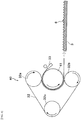
- FIG. 3 illustrates an example of a manufacturing apparatus 30 of the toothed belt 1.
- the manufacturing apparatus 30 includes a molding drum (mold) 31, a pressing band 32, an extrusion head 33, a cord supplying device which is not illustrated, and a back sheet supplying device which is not illustrated.
- the molding drum 31 is provided with: a tooth-molding groove formed at a predetermined interval P on the outer periphery of the tubular shape; a flange which is not illustrated but attached to both ends in an axial direction of the tubular shape to prevent the thermoplastic elastomer from flowing out; a heating means capable of heating the vicinity of the tooth-molding groove from normal temperature to 120°C; and a driving means for rotatably driving the molding drum 31 in an arrow direction (counterclockwise direction).
- the pressing band 32 is an endless metal band wound around pulleys 32a and 32b, which are closely arranged on the upper side and the lower side of the molding drum 31, and a pulley 32c, which is disposed at a position separated from the pulleys 32a and 32b.
- This metal band is wound around about half of the outer periphery of the not-illustrated flange at both ends of the molding drum 31.
- the pulley 32c applies a predetermined tension to the pressing band 32 by being moved in the left direction of the drawing.
- a molding cavity is formed between the pressing band 32 and the molding drum 31.
- the extrusion head 33 is disposed in the vicinity of the outer periphery of the molding drum 31 in front of the entrance of the cavity and causes the melted thermoplastic elastomer to flow out toward the cavity.
- the extrusion head 33 is preferably disposed toward the cavity from between the molding drum and the array of cords. This is because the melted thermoplastic elastomer can be sufficiently supplied to the tooth-molding groove.
- the cord supplying device continuously supplies the array of cords, which contains the cords 4 arranged in the axial direction of the molding drum 31 with an interval provided therebetween, to the outer periphery of the molding drum 31.
- the back sheet supplying device continuously supplies the back sheet 3 to the outer peripheral side of the pressing band 32 in a direction in which the uneven shape 6 faces the cord 4.
- FIG. 4 illustrates an example of a manufacturing apparatus 40 of the back sheet 3 having the uneven shape 6.
- the manufacturing apparatus of the toothed belt 1 illustrated in FIG. 3 can be partially changed and diverted.
- the same reference numerals as those in FIG. 3 are attached to diverted parts, and a detailed description thereof will be omitted.
- Changed parts are the outer peripheral shape of the molding drum 41 and that the cord supplying device and the back sheet supplying device, which are not illustrated, are not used.
- the molding drum 41 having an uneven-molding groove formed at the predetermined interval S on the outer periphery of the tubular shape is used. Also a flange, which is not illustrated, having a height matching the thickness of the back sheet is used. The change may be made only on the outer peripheral side or on the whole of the molding drum 41.
- thermoplastic elastomer material By using this molding drum 41, without supplying the cords and the back sheet, only the melted thermoplastic elastomer material is supplied and continuously solidified, whereby a back sheet having an uneven shape can be manufactured.
- the configuration of the apparatus can be simplified by diverting most of the apparatus as in this way.
- the back sheet 3 having an uneven shape is molded (first step).
- the melted material to be the belt main body 2 is supplied from the extrusion head (die) 33 of the extruder and laminated so as to form a two-layer toothed belt 1 (second step).
- thermoplastic elastomer heated and melted is supplied from the extrusion head 33 of the extruder while rotatably driving the molding drum (mold) 41 in the arrow direction in FIG. 4 , the thermoplastic elastomer is caught in the cavity between the molding drum 41 and the pressing band 32 in accordance with the rotation of the molding drum 41.
- thermoplastic elastomer is filled in the uneven-molding groove of the molding drum 41 by the pressure from the pressing band 32, whereby the uneven shape 6 of the back sheet 3 is molded and simultaneously, the back surface of the back sheet 3 is molded.
- the back sheet 3 having the uneven shape can be manufactured by continuously cooling and solidifying the thermoplastic elastomer naturally while molding in this manner.
- Manufacturing conditions are, for example, as follows: melting temperature of thermoplastic elastomer: from 200 to 230°C, temperature of molding drum: from normal temperature to 120°C, and feeding speed of molding drum 41: from 0.1 to 1.0 m/min.
- an array of cords in which a predetermined number of cords 4 are arranged in parallel is supplied to the outer periphery of the molding drum 31 and at the same time, the back sheet 3 having the uneven shape is supplied to the outer peripheral side of the pressing band 32 between the pulley 32a and the molding drum 31.
- thermoplastic elastomer heated and melted is supplied from the extrusion head 33 of the extruder at the same time as the back sheet 3 having the uneven shape and the cords 4 are caught in between the pulley 32a and the molding drum 31, the back sheet 3 having the uneven shape, the cords 4, and the thermoplastic elastomer are caught in the cavity between the molding drum 31 and the pressing band 32 in accordance with the rotation of the molding drum 31.
- thermoplastic elastomer is filled in the tooth-molding groove of the molding drum 31 by the pressure from the pressing band 32, whereby the tooth portion 2b of the toothed belt 1 is molded and simultaneously, the belt main body 2 of the toothed belt 1 having the cords 4 buried between the back sheet 3 having the uneven shape and the outer periphery of the molding drum 31 is molded.
- a two-layer toothed belt 1 with an end in which the back sheet 3 having the uneven shape and the belt main body 2 of the toothed belt are integrally fusion-joined can be manufactured by continuously cooling and solidifying the thermoplastic elastomer naturally while molding in this manner. This fusion-joining is performed on the surface of the uneven shape of the back sheet 3, and the uneven shape thereof is maintained.
- Manufacturing conditions are, for example, as follows: melting temperature of thermoplastic elastomer: from 200 to 230°C, temperature of molding drum: from normal temperature to 120°C, and feeding speed of cord and belt: from 0.1 to 1.0 m/min.
- Examples of using such a toothed belt 1 include a lifting and transporting apparatus 50 that reciprocates in a certain range as illustrated in in FIG. 5 .
- toothed belts 55 and 56 which are meshed with toothed pulleys 51 and 53 and toothed pulleys 52 and 54 arranged on the upper side and the lower side, are used.
- the toothed pulley 52 on the lower left side which is a driving pulley, is rotated/reversely rotated.
- the other toothed pulleys 51, 53, and 54 are synchronously driven via the toothed belts 55 and 56.
- the power is transmitted to the belt mechanism, and a transported object W placed on the loading platform 57 fixed to the two belt mechanisms moves up and down.
- the toothed belt 1 with an end manufactured as described above is used by being cut into a predetermined width and a predetermined length, and joining both end portions in the length direction to be endless.
- a fixture 58 for fixing the loading platform 57 is attached to the toothed belts 55 and 56.
- An example of this fixture 58 is one in which, as illustrated in FIG. 1 of JP-A 2015-3821 , a shaft member and a back plate are arranged and are fixed with screws so as to interpose the belt back portion at between a tooth portion and a tooth portion.
- Another example of the fixture 58 is one in which, as illustrated in FIG. 6 of JP-A 2009-112217 , a through hole is provided in the width direction of the tooth portion, a shaft member is inserted into the through hole, and a nut is screwed into the tip end screw of the shaft member to fix it.
- the back portion of the toothed belt 1 is formed to be thick, and thus it has sufficient mounting strength.
- the thickness is increased with the adhesion interface of the uneven shape, and thus there is little possibility of causing peeling at the adhesion interface.
- Still another example may be one in which a through hole is provided in the back portion of the toothed belt 1, a shaft member is inserted into the through hole, and a nut is screwed into the tip end screw of the shaft member to fix it.
- Belt width 25 mm
- thickness of back sheet having uneven shape 2.5 mm
- tooth pitch 25 mm
- total belt thickness 14 mm
- constituent material thermoplastic polyurethane elastomer (both back sheet and belt main body)
- cord diameter ⁇ 1.9 mm (para-aramid fiber "TOWARON (registered trademark)").
- Belt width 25 mm
- back flat sheet thickness 2.0 mm
- belt tooth pitch 25 mm
- total belt thickness 14 mm
- constituent material and cord diameter the same as those in Example.
- a test specimen having a length of 125 mm was taken from the manufactured belt and a tensile test (tensile speed: 100 mm/min) was carried out by using a tensile tester (Autograph), and the adhesive force until the sheet was peeled off was compared.
- the sheet adhesive force was improved by 27% as compared to the case where the back sheet was a flat sheet.
Landscapes
- Engineering & Computer Science (AREA)
- General Engineering & Computer Science (AREA)
- Mechanical Engineering (AREA)
- Extrusion Moulding Of Plastics Or The Like (AREA)
Claims (5)
- Courroie crantée (1) comprenant :un corps principal de courroie (2) comprenant un ensemble d'un cordon (4), une partie de cran (2b) formée sur le côté inférieur de l'ensemble du cordon (4) et agencée au niveau d'un intervalle prédéterminé le long d'une direction longitudinale du cordon (4), et une partie de surface arrière (2a) formée sur le côté supérieur de l'ensemble du cordon (4) et ayant le cordon (4) intégré dans celle-ci, qui sont moulés d'un seul tenant avec une première composition d'élastomère thermoplastique ; etune feuille arrière (3) collée au côté de la partie de surface arrière (2a) du corps principal de courroie (2) et constituée d'une seconde composition d'élastomère thermoplastique,dans laquelle la feuille arrière (3) a une forme non plane dans une surface sur le côté adhésif,dans laquelle la forme non plane est formée en agençant des parties convexes et concaves le long de la direction longitudinale du cordon (4) au niveau d'un intervalle prédéterminé, caractérisée en ce que l'intervalle prédéterminé (S) des parties convexes et concaves est plus petit que l'intervalle prédéterminé (P) de la partie de cran (2b).
- Courroie crantée (1) selon la revendication 1,
dans laquelle la seconde composition d'élastomère thermoplastique formant la feuille arrière (3) a une propriété différente de celle de la première composition d'élastomère thermoplastique formant le corps principal de courroie (2). - Procédé de fabrication de la courroie crantée (1) comme décrit dans la revendication 1, comprenant :une première étape de formation de la feuille arrière (3) ayant la forme non plane, etune seconde étape d'assemblage par fusion de la feuille arrière (3) ayant la forme non plane et du corps principal de courroie (2) tout en moulant en continu le corps principal de courroie (2), comprenant :l'utilisation d'un appareil de fabrication de courroie incluant un tambour de moulage ayant une rainure de moulage de cran formée sur le pourtour extérieur au niveau d'un intervalle prédéterminé, une bande de pression disposée de façon à être enroulée autour du côté de pourtour extérieur du tambour de moulage, et une tête d'extrusion fournissant la première composition d'élastomère thermoplastique à une cavité formée entre le tambour de moulage et la bande de pression,la rotation du tambour de moulage, ettout en fournissant l'ensemble du cordon (4) au pourtour extérieur du tambour de moulage, la fourniture de la feuille arrière (3) ayant la forme non plane sur le pourtour intérieur de la bande de pression et la fourniture simultanée de la première composition d'élastomère thermoplastique chauffée et fondue de la tête d'extrusion à la cavité.
- Procédé de fabrication de la courroie crantée (1) selon la revendication 3,
dans lequel la tête d'extrusion est disposée vers la cavité entre le tambour de moulage et l'ensemble du cordon (4). - Procédé de fabrication de la courroie crantée (1) selon la revendication 3,
dans lequel la feuille arrière (3) ayant la forme non plane est formée en continu :en utilisant un appareil de fabrication de courroie incluant un tambour de moulage ayant une rainure non plane formée sur le pourtour extérieur au niveau d'un intervalle prédéterminé, une bande de pression disposée de façon à être enroulée autour du côté de pourtour extérieur du tambour de moulage, et une tête d'extrusion fournissant la seconde composition d'élastomère thermoplastique à une cavité formée entre le tambour de moulage et la bande de pression, eten fournissant la seconde composition d'élastomère thermoplastique chauffée et fondue de la tête d'extrusion à la cavité.
Applications Claiming Priority (3)
| Application Number | Priority Date | Filing Date | Title |
|---|---|---|---|
| JP2016104344 | 2016-05-25 | ||
| JP2017097103A JP6553674B2 (ja) | 2016-05-25 | 2017-05-16 | 歯付きベルト及びその製造方法 |
| PCT/JP2017/019375 WO2017204250A1 (fr) | 2016-05-25 | 2017-05-24 | Courroie crantée et procédé de fabrication de celle-ci |
Publications (3)
| Publication Number | Publication Date |
|---|---|
| EP3467342A1 EP3467342A1 (fr) | 2019-04-10 |
| EP3467342A4 EP3467342A4 (fr) | 2020-01-01 |
| EP3467342B1 true EP3467342B1 (fr) | 2020-11-25 |
Family
ID=60575564
Family Applications (1)
| Application Number | Title | Priority Date | Filing Date |
|---|---|---|---|
| EP17802836.1A Not-in-force EP3467342B1 (fr) | 2016-05-25 | 2017-05-24 | Courroie crantée et procédé de fabrication de celle-ci |
Country Status (7)
| Country | Link |
|---|---|
| US (1) | US10864691B2 (fr) |
| EP (1) | EP3467342B1 (fr) |
| JP (1) | JP6553674B2 (fr) |
| KR (1) | KR102147220B1 (fr) |
| CN (1) | CN109154358B (fr) |
| CA (1) | CA3020579C (fr) |
| TW (1) | TWI625478B (fr) |
Families Citing this family (12)
| Publication number | Priority date | Publication date | Assignee | Title |
|---|---|---|---|---|
| EP3988153B1 (fr) | 2015-03-31 | 2024-04-24 | Fisher & Paykel Healthcare Limited | Interface utilisateur pour l'alimentation en gaz à une voie respiratoire |
| CN121668497A (zh) | 2016-08-11 | 2026-03-17 | 费雪派克医疗保健有限公司 | 可塌缩导管、患者接口和头戴具连接器 |
| CN108910399A (zh) * | 2018-08-31 | 2018-11-30 | 佛山市加德纳机械配件有限公司 | 一种同步输送带及其制备方法 |
| CN113386105A (zh) * | 2020-03-13 | 2021-09-14 | 科沃斯机器人股份有限公司 | 一种自移动机器人、同步带及同步带的制备方法 |
| JP7007508B2 (ja) | 2020-04-28 | 2022-01-24 | 三ツ星ベルト株式会社 | ベルト伝動機構 |
| JP7281573B2 (ja) * | 2021-04-06 | 2023-05-25 | 三ツ星ベルト株式会社 | 歯付ベルト |
| CN117222826B (zh) * | 2021-04-30 | 2024-08-23 | 阪东化学株式会社 | 齿形带 |
| JP7676234B2 (ja) * | 2021-06-15 | 2025-05-14 | Nok株式会社 | 樹脂製ベルトの製造方法及び樹脂製ベルト製造装置 |
| CN113696459B (zh) * | 2021-08-25 | 2023-05-12 | 宁波慈光同步带有限公司 | 一种双面齿同步带的加工装置及其加工方法 |
| IT202200009404A1 (it) * | 2022-05-06 | 2023-11-06 | Gambini Spa | Gruppo goffratore. |
| CN116278088B (zh) * | 2022-12-08 | 2025-10-14 | 奥力孚传动科技股份有限公司 | 防水防腐蚀洗车机专用同步带及工艺 |
| TWI851383B (zh) * | 2023-08-23 | 2024-08-01 | 捷鋮興業有限公司 | 擋塊皮帶加工機 |
Family Cites Families (33)
| Publication number | Priority date | Publication date | Assignee | Title |
|---|---|---|---|---|
| DE1444549A1 (de) * | 1962-12-11 | 1968-12-12 | Pierre Baranger | OElhaltige Emulsionen und Verfahren zu ihrer Herstellung |
| US3535946A (en) * | 1968-01-05 | 1970-10-27 | Uniroyal Inc | Positive drive belt |
| US4228692A (en) * | 1977-08-15 | 1980-10-21 | Dayco Corporation | Endless power transmission belt and method of manufacture |
| JPS6224853Y2 (fr) | 1979-05-25 | 1987-06-25 | ||
| US4311474A (en) * | 1979-09-14 | 1982-01-19 | Dayco Corporation | Synchronous belt and method for making the same |
| IT1131268B (it) * | 1980-06-05 | 1986-06-18 | Pirelli | Cinghia dentata |
| US4838843A (en) * | 1982-04-16 | 1989-06-13 | The Gates Rubber Company | Toothed belt |
| US4586973A (en) * | 1983-06-09 | 1986-05-06 | Dayco Corporation | Method of making belt |
| US4583963A (en) * | 1983-06-09 | 1986-04-22 | Dayco Corporation | Belt construction having enhanced tooth strength |
| US4504342A (en) * | 1983-06-09 | 1985-03-12 | Dayco Corporation | Belt construction and method of making same |
| US4626232A (en) * | 1984-10-09 | 1986-12-02 | Dayco Corporation | Belt construction and method of making the same |
| JP3200088B2 (ja) * | 1991-05-17 | 2001-08-20 | 三ツ星ベルト株式会社 | 歯付ベルト |
| JPH0694178A (ja) | 1992-09-10 | 1994-04-05 | Sekisui Chem Co Ltd | 配管用継手 |
| JPH0942381A (ja) | 1995-07-27 | 1997-02-10 | Unitta Co Ltd | 色付き二輪車用動力伝達ベルト及びその製造方法 |
| US5614267A (en) * | 1996-01-30 | 1997-03-25 | Eutectic Corporation | Repair of worn conveyor belting using thermally applied polymer coatings |
| DE69708401T2 (de) | 1996-06-26 | 2002-08-01 | Idemitsu Petrochemical Co | Verfahren zum Musterprägen einer Folie und Vorrichtung zur Musterprägung |
| US5807194A (en) * | 1996-10-31 | 1998-09-15 | The Gates Corporation | Toothed belt |
| US5971879A (en) * | 1997-04-22 | 1999-10-26 | The Gates Corporation | Belt reinforcing material and belt constructed therewith |
| JPH1170589A (ja) | 1997-08-29 | 1999-03-16 | Mitsuboshi Belting Ltd | 熱可塑性歯付ベルトの製造方法 |
| US6945891B2 (en) | 2001-01-12 | 2005-09-20 | The Gates Corporation | Power transmission belt and method |
| DE102004030722A1 (de) * | 2004-06-25 | 2006-01-19 | Contitech Antriebssysteme Gmbh | Mit Festigkeitsträgern versehener Flachriemen für Aufzugsanlagen |
| US8197372B2 (en) | 2006-04-07 | 2012-06-12 | The Gates Corporation | Power transmission belt |
| CN103161879A (zh) | 2007-09-14 | 2013-06-19 | 盖茨优霓塔亚洲有限公司 | 多楔带以及制造该多楔带的方法 |
| JP5068143B2 (ja) | 2007-11-05 | 2012-11-07 | 株式会社オシキリ | パン生地搬送装置及びプルーファー |
| JP4990109B2 (ja) | 2007-11-27 | 2012-08-01 | ゲイツ・ユニッタ・アジア株式会社 | 歯付きベルト |
| US8070634B2 (en) * | 2008-05-02 | 2011-12-06 | The Gates Corporation | Synchronous belt sprocket |
| US8192315B2 (en) * | 2009-02-24 | 2012-06-05 | Dayco Products, Llc | V-ribbed belt having an outer surface with improved coefficient of friction |
| US9944763B2 (en) * | 2009-12-01 | 2018-04-17 | Gates Corporation | Polyurea-urethane cord treatment for power transmission belt and belt |
| KR20160088949A (ko) | 2011-12-14 | 2016-07-26 | 게이츠 코포레이션 | 개방-단부형 열가소성 벨트 장치를 제조하기 위한 시스템 및 방법 |
| JP5914202B2 (ja) | 2012-06-18 | 2016-05-11 | 三ツ星ベルト株式会社 | 伝動ベルト用カバー布および歯付ベルト |
| EP2881096B1 (fr) | 2012-08-02 | 2017-08-30 | Zuiko Corporation | Procédé et dispositif de production de feuille composite |
| AU2014258911A1 (en) | 2013-04-26 | 2015-01-15 | Panasonic Corporation | Optical semiconductor electrode, and water photolysis method using photoelectrochemical cell provided with same |
| JP6061797B2 (ja) | 2013-06-24 | 2017-01-18 | ホクショー株式会社 | 垂直搬送機 |
-
2017
- 2017-05-16 JP JP2017097103A patent/JP6553674B2/ja active Active
- 2017-05-24 KR KR1020187033392A patent/KR102147220B1/ko not_active Expired - Fee Related
- 2017-05-24 CN CN201780030990.5A patent/CN109154358B/zh not_active Expired - Fee Related
- 2017-05-24 CA CA3020579A patent/CA3020579C/fr active Active
- 2017-05-24 US US16/301,919 patent/US10864691B2/en not_active Expired - Fee Related
- 2017-05-24 EP EP17802836.1A patent/EP3467342B1/fr not_active Not-in-force
- 2017-05-25 TW TW106117379A patent/TWI625478B/zh not_active IP Right Cessation
Also Published As
| Publication number | Publication date |
|---|---|
| TWI625478B (zh) | 2018-06-01 |
| KR20180137524A (ko) | 2018-12-27 |
| KR102147220B1 (ko) | 2020-08-24 |
| CA3020579A1 (fr) | 2017-11-30 |
| CA3020579C (fr) | 2020-07-21 |
| US10864691B2 (en) | 2020-12-15 |
| EP3467342A1 (fr) | 2019-04-10 |
| CN109154358B (zh) | 2020-07-28 |
| CN109154358A (zh) | 2019-01-04 |
| TW201741573A (zh) | 2017-12-01 |
| EP3467342A4 (fr) | 2020-01-01 |
| JP2017215038A (ja) | 2017-12-07 |
| US20200198268A1 (en) | 2020-06-25 |
| JP6553674B2 (ja) | 2019-07-31 |
Similar Documents
| Publication | Publication Date | Title |
|---|---|---|
| US10864691B2 (en) | Toothed belt and manufacturing method therefor | |
| EP2987629B1 (fr) | Procédé de fabrication d'une courroie thermoplastique à extrémité ouverte | |
| EP3214339B1 (fr) | Courroie plate, mecanisme a courroie, mecanisme elevateur a courroie, procédé de fixation, et procédé pour la fabrication de courroie plate | |
| AU2012351941B2 (en) | Apparatus and method for making endless reinforced belts | |
| CN102482036B (zh) | 平带 | |
| WO2017204250A1 (fr) | Courroie crantée et procédé de fabrication de celle-ci | |
| JP4463052B2 (ja) | 移動手摺の製造方法 | |
| WO2008027153A1 (fr) | Procédé de fabrication d'une courroie dentée | |
| JP2007118561A (ja) | 伝動ベルトの製造方法及び金型装置 | |
| JP7229000B2 (ja) | 歯付ベルトの製造方法及び歯付ベルト | |
| JP2008273003A (ja) | 両面歯付ベルトの製造方法 | |
| AU2013300679A1 (en) | Method for joining conveyer belt |
Legal Events
| Date | Code | Title | Description |
|---|---|---|---|
| STAA | Information on the status of an ep patent application or granted ep patent |
Free format text: STATUS: THE INTERNATIONAL PUBLICATION HAS BEEN MADE |
|
| PUAI | Public reference made under article 153(3) epc to a published international application that has entered the european phase |
Free format text: ORIGINAL CODE: 0009012 |
|
| STAA | Information on the status of an ep patent application or granted ep patent |
Free format text: STATUS: REQUEST FOR EXAMINATION WAS MADE |
|
| 17P | Request for examination filed |
Effective date: 20181113 |
|
| AK | Designated contracting states |
Kind code of ref document: A1 Designated state(s): AL AT BE BG CH CY CZ DE DK EE ES FI FR GB GR HR HU IE IS IT LI LT LU LV MC MK MT NL NO PL PT RO RS SE SI SK SM TR |
|
| AX | Request for extension of the european patent |
Extension state: BA ME |
|
| DAV | Request for validation of the european patent (deleted) | ||
| DAX | Request for extension of the european patent (deleted) | ||
| A4 | Supplementary search report drawn up and despatched |
Effective date: 20191204 |
|
| RIC1 | Information provided on ipc code assigned before grant |
Ipc: F16G 1/28 20060101AFI20191128BHEP Ipc: B29D 29/08 20060101ALI20191128BHEP |
|
| GRAP | Despatch of communication of intention to grant a patent |
Free format text: ORIGINAL CODE: EPIDOSNIGR1 |
|
| STAA | Information on the status of an ep patent application or granted ep patent |
Free format text: STATUS: GRANT OF PATENT IS INTENDED |
|
| INTG | Intention to grant announced |
Effective date: 20200623 |
|
| GRAS | Grant fee paid |
Free format text: ORIGINAL CODE: EPIDOSNIGR3 |
|
| GRAA | (expected) grant |
Free format text: ORIGINAL CODE: 0009210 |
|
| STAA | Information on the status of an ep patent application or granted ep patent |
Free format text: STATUS: THE PATENT HAS BEEN GRANTED |
|
| AK | Designated contracting states |
Kind code of ref document: B1 Designated state(s): AL AT BE BG CH CY CZ DE DK EE ES FI FR GB GR HR HU IE IS IT LI LT LU LV MC MK MT NL NO PL PT RO RS SE SI SK SM TR |
|
| REG | Reference to a national code |
Ref country code: GB Ref legal event code: FG4D |
|
| REG | Reference to a national code |
Ref country code: CH Ref legal event code: EP |
|
| REG | Reference to a national code |
Ref country code: AT Ref legal event code: REF Ref document number: 1338694 Country of ref document: AT Kind code of ref document: T Effective date: 20201215 |
|
| REG | Reference to a national code |
Ref country code: DE Ref legal event code: R096 Ref document number: 602017028477 Country of ref document: DE |
|
| REG | Reference to a national code |
Ref country code: IE Ref legal event code: FG4D |
|
| REG | Reference to a national code |
Ref country code: AT Ref legal event code: MK05 Ref document number: 1338694 Country of ref document: AT Kind code of ref document: T Effective date: 20201125 |
|
| REG | Reference to a national code |
Ref country code: NL Ref legal event code: MP Effective date: 20201125 |
|
| PG25 | Lapsed in a contracting state [announced via postgrant information from national office to epo] |
Ref country code: GR Free format text: LAPSE BECAUSE OF FAILURE TO SUBMIT A TRANSLATION OF THE DESCRIPTION OR TO PAY THE FEE WITHIN THE PRESCRIBED TIME-LIMIT Effective date: 20210226 Ref country code: NO Free format text: LAPSE BECAUSE OF FAILURE TO SUBMIT A TRANSLATION OF THE DESCRIPTION OR TO PAY THE FEE WITHIN THE PRESCRIBED TIME-LIMIT Effective date: 20210225 Ref country code: FI Free format text: LAPSE BECAUSE OF FAILURE TO SUBMIT A TRANSLATION OF THE DESCRIPTION OR TO PAY THE FEE WITHIN THE PRESCRIBED TIME-LIMIT Effective date: 20201125 Ref country code: RS Free format text: LAPSE BECAUSE OF FAILURE TO SUBMIT A TRANSLATION OF THE DESCRIPTION OR TO PAY THE FEE WITHIN THE PRESCRIBED TIME-LIMIT Effective date: 20201125 Ref country code: PT Free format text: LAPSE BECAUSE OF FAILURE TO SUBMIT A TRANSLATION OF THE DESCRIPTION OR TO PAY THE FEE WITHIN THE PRESCRIBED TIME-LIMIT Effective date: 20210325 |
|
| PG25 | Lapsed in a contracting state [announced via postgrant information from national office to epo] |
Ref country code: SE Free format text: LAPSE BECAUSE OF FAILURE TO SUBMIT A TRANSLATION OF THE DESCRIPTION OR TO PAY THE FEE WITHIN THE PRESCRIBED TIME-LIMIT Effective date: 20201125 Ref country code: LV Free format text: LAPSE BECAUSE OF FAILURE TO SUBMIT A TRANSLATION OF THE DESCRIPTION OR TO PAY THE FEE WITHIN THE PRESCRIBED TIME-LIMIT Effective date: 20201125 Ref country code: PL Free format text: LAPSE BECAUSE OF FAILURE TO SUBMIT A TRANSLATION OF THE DESCRIPTION OR TO PAY THE FEE WITHIN THE PRESCRIBED TIME-LIMIT Effective date: 20201125 Ref country code: IS Free format text: LAPSE BECAUSE OF FAILURE TO SUBMIT A TRANSLATION OF THE DESCRIPTION OR TO PAY THE FEE WITHIN THE PRESCRIBED TIME-LIMIT Effective date: 20210325 Ref country code: BG Free format text: LAPSE BECAUSE OF FAILURE TO SUBMIT A TRANSLATION OF THE DESCRIPTION OR TO PAY THE FEE WITHIN THE PRESCRIBED TIME-LIMIT Effective date: 20210225 Ref country code: AT Free format text: LAPSE BECAUSE OF FAILURE TO SUBMIT A TRANSLATION OF THE DESCRIPTION OR TO PAY THE FEE WITHIN THE PRESCRIBED TIME-LIMIT Effective date: 20201125 |
|
| REG | Reference to a national code |
Ref country code: LT Ref legal event code: MG9D |
|
| PG25 | Lapsed in a contracting state [announced via postgrant information from national office to epo] |
Ref country code: HR Free format text: LAPSE BECAUSE OF FAILURE TO SUBMIT A TRANSLATION OF THE DESCRIPTION OR TO PAY THE FEE WITHIN THE PRESCRIBED TIME-LIMIT Effective date: 20201125 |
|
| PG25 | Lapsed in a contracting state [announced via postgrant information from national office to epo] |
Ref country code: RO Free format text: LAPSE BECAUSE OF FAILURE TO SUBMIT A TRANSLATION OF THE DESCRIPTION OR TO PAY THE FEE WITHIN THE PRESCRIBED TIME-LIMIT Effective date: 20201125 Ref country code: SK Free format text: LAPSE BECAUSE OF FAILURE TO SUBMIT A TRANSLATION OF THE DESCRIPTION OR TO PAY THE FEE WITHIN THE PRESCRIBED TIME-LIMIT Effective date: 20201125 Ref country code: EE Free format text: LAPSE BECAUSE OF FAILURE TO SUBMIT A TRANSLATION OF THE DESCRIPTION OR TO PAY THE FEE WITHIN THE PRESCRIBED TIME-LIMIT Effective date: 20201125 Ref country code: CZ Free format text: LAPSE BECAUSE OF FAILURE TO SUBMIT A TRANSLATION OF THE DESCRIPTION OR TO PAY THE FEE WITHIN THE PRESCRIBED TIME-LIMIT Effective date: 20201125 Ref country code: LT Free format text: LAPSE BECAUSE OF FAILURE TO SUBMIT A TRANSLATION OF THE DESCRIPTION OR TO PAY THE FEE WITHIN THE PRESCRIBED TIME-LIMIT Effective date: 20201125 Ref country code: SM Free format text: LAPSE BECAUSE OF FAILURE TO SUBMIT A TRANSLATION OF THE DESCRIPTION OR TO PAY THE FEE WITHIN THE PRESCRIBED TIME-LIMIT Effective date: 20201125 |
|
| REG | Reference to a national code |
Ref country code: DE Ref legal event code: R097 Ref document number: 602017028477 Country of ref document: DE |
|
| PG25 | Lapsed in a contracting state [announced via postgrant information from national office to epo] |
Ref country code: DK Free format text: LAPSE BECAUSE OF FAILURE TO SUBMIT A TRANSLATION OF THE DESCRIPTION OR TO PAY THE FEE WITHIN THE PRESCRIBED TIME-LIMIT Effective date: 20201125 |
|
| PLBE | No opposition filed within time limit |
Free format text: ORIGINAL CODE: 0009261 |
|
| STAA | Information on the status of an ep patent application or granted ep patent |
Free format text: STATUS: NO OPPOSITION FILED WITHIN TIME LIMIT |
|
| PG25 | Lapsed in a contracting state [announced via postgrant information from national office to epo] |
Ref country code: NL Free format text: LAPSE BECAUSE OF FAILURE TO SUBMIT A TRANSLATION OF THE DESCRIPTION OR TO PAY THE FEE WITHIN THE PRESCRIBED TIME-LIMIT Effective date: 20201125 Ref country code: AL Free format text: LAPSE BECAUSE OF FAILURE TO SUBMIT A TRANSLATION OF THE DESCRIPTION OR TO PAY THE FEE WITHIN THE PRESCRIBED TIME-LIMIT Effective date: 20201125 |
|
| 26N | No opposition filed |
Effective date: 20210826 |
|
| PG25 | Lapsed in a contracting state [announced via postgrant information from national office to epo] |
Ref country code: SI Free format text: LAPSE BECAUSE OF FAILURE TO SUBMIT A TRANSLATION OF THE DESCRIPTION OR TO PAY THE FEE WITHIN THE PRESCRIBED TIME-LIMIT Effective date: 20201125 |
|
| REG | Reference to a national code |
Ref country code: CH Ref legal event code: PL |
|
| PG25 | Lapsed in a contracting state [announced via postgrant information from national office to epo] |
Ref country code: LI Free format text: LAPSE BECAUSE OF NON-PAYMENT OF DUE FEES Effective date: 20210531 Ref country code: LU Free format text: LAPSE BECAUSE OF NON-PAYMENT OF DUE FEES Effective date: 20210524 Ref country code: MC Free format text: LAPSE BECAUSE OF FAILURE TO SUBMIT A TRANSLATION OF THE DESCRIPTION OR TO PAY THE FEE WITHIN THE PRESCRIBED TIME-LIMIT Effective date: 20201125 Ref country code: CH Free format text: LAPSE BECAUSE OF NON-PAYMENT OF DUE FEES Effective date: 20210531 Ref country code: ES Free format text: LAPSE BECAUSE OF FAILURE TO SUBMIT A TRANSLATION OF THE DESCRIPTION OR TO PAY THE FEE WITHIN THE PRESCRIBED TIME-LIMIT Effective date: 20201125 |
|
| REG | Reference to a national code |
Ref country code: BE Ref legal event code: MM Effective date: 20210531 |
|
| PG25 | Lapsed in a contracting state [announced via postgrant information from national office to epo] |
Ref country code: IE Free format text: LAPSE BECAUSE OF NON-PAYMENT OF DUE FEES Effective date: 20210524 |
|
| PG25 | Lapsed in a contracting state [announced via postgrant information from national office to epo] |
Ref country code: IS Free format text: LAPSE BECAUSE OF FAILURE TO SUBMIT A TRANSLATION OF THE DESCRIPTION OR TO PAY THE FEE WITHIN THE PRESCRIBED TIME-LIMIT Effective date: 20210325 |
|
| PG25 | Lapsed in a contracting state [announced via postgrant information from national office to epo] |
Ref country code: BE Free format text: LAPSE BECAUSE OF NON-PAYMENT OF DUE FEES Effective date: 20210531 |
|
| PGFP | Annual fee paid to national office [announced via postgrant information from national office to epo] |
Ref country code: IT Payment date: 20220412 Year of fee payment: 6 Ref country code: GB Payment date: 20220401 Year of fee payment: 6 Ref country code: FR Payment date: 20220408 Year of fee payment: 6 Ref country code: DE Payment date: 20220329 Year of fee payment: 6 |
|
| PG25 | Lapsed in a contracting state [announced via postgrant information from national office to epo] |
Ref country code: CY Free format text: LAPSE BECAUSE OF FAILURE TO SUBMIT A TRANSLATION OF THE DESCRIPTION OR TO PAY THE FEE WITHIN THE PRESCRIBED TIME-LIMIT Effective date: 20201125 |
|
| PG25 | Lapsed in a contracting state [announced via postgrant information from national office to epo] |
Ref country code: HU Free format text: LAPSE BECAUSE OF FAILURE TO SUBMIT A TRANSLATION OF THE DESCRIPTION OR TO PAY THE FEE WITHIN THE PRESCRIBED TIME-LIMIT; INVALID AB INITIO Effective date: 20170524 |
|
| REG | Reference to a national code |
Ref country code: DE Ref legal event code: R119 Ref document number: 602017028477 Country of ref document: DE |
|
| GBPC | Gb: european patent ceased through non-payment of renewal fee |
Effective date: 20230524 |
|
| PG25 | Lapsed in a contracting state [announced via postgrant information from national office to epo] |
Ref country code: MK Free format text: LAPSE BECAUSE OF FAILURE TO SUBMIT A TRANSLATION OF THE DESCRIPTION OR TO PAY THE FEE WITHIN THE PRESCRIBED TIME-LIMIT Effective date: 20201125 Ref country code: IT Free format text: LAPSE BECAUSE OF NON-PAYMENT OF DUE FEES Effective date: 20230524 Ref country code: DE Free format text: LAPSE BECAUSE OF NON-PAYMENT OF DUE FEES Effective date: 20231201 Ref country code: GB Free format text: LAPSE BECAUSE OF NON-PAYMENT OF DUE FEES Effective date: 20230524 |
|
| PG25 | Lapsed in a contracting state [announced via postgrant information from national office to epo] |
Ref country code: FR Free format text: LAPSE BECAUSE OF NON-PAYMENT OF DUE FEES Effective date: 20230531 |
|
| PG25 | Lapsed in a contracting state [announced via postgrant information from national office to epo] |
Ref country code: MT Free format text: LAPSE BECAUSE OF FAILURE TO SUBMIT A TRANSLATION OF THE DESCRIPTION OR TO PAY THE FEE WITHIN THE PRESCRIBED TIME-LIMIT Effective date: 20201125 |
|
| PG25 | Lapsed in a contracting state [announced via postgrant information from national office to epo] |
Ref country code: TR Free format text: LAPSE BECAUSE OF FAILURE TO SUBMIT A TRANSLATION OF THE DESCRIPTION OR TO PAY THE FEE WITHIN THE PRESCRIBED TIME-LIMIT Effective date: 20201125 |