EP3467450A1 - Appareil de mesure de niveau de remplissage à radar pourvu d'un système radar sur puce - Google Patents
Appareil de mesure de niveau de remplissage à radar pourvu d'un système radar sur puce Download PDFInfo
- Publication number
- EP3467450A1 EP3467450A1 EP17195233.6A EP17195233A EP3467450A1 EP 3467450 A1 EP3467450 A1 EP 3467450A1 EP 17195233 A EP17195233 A EP 17195233A EP 3467450 A1 EP3467450 A1 EP 3467450A1
- Authority
- EP
- European Patent Office
- Prior art keywords
- radar
- level gauge
- channels
- transmission
- elements
- Prior art date
- Legal status (The legal status is an assumption and is not a legal conclusion. Google has not performed a legal analysis and makes no representation as to the accuracy of the status listed.)
- Granted
Links
Images



Classifications
-
- G—PHYSICS
- G01—MEASURING; TESTING
- G01F—MEASURING VOLUME, VOLUME FLOW, MASS FLOW OR LIQUID LEVEL; METERING BY VOLUME
- G01F23/00—Indicating or measuring liquid level or level of fluent solid material, e.g. indicating in terms of volume or indicating by means of an alarm
- G01F23/22—Indicating or measuring liquid level or level of fluent solid material, e.g. indicating in terms of volume or indicating by means of an alarm by measuring physical variables, other than linear dimensions, pressure or weight, dependent on the level to be measured, e.g. by difference of heat transfer of steam or water
- G01F23/28—Indicating or measuring liquid level or level of fluent solid material, e.g. indicating in terms of volume or indicating by means of an alarm by measuring physical variables, other than linear dimensions, pressure or weight, dependent on the level to be measured, e.g. by difference of heat transfer of steam or water by measuring the variations of parameters of electromagnetic or acoustic waves applied directly to the liquid or fluent solid material
- G01F23/284—Electromagnetic waves
-
- G—PHYSICS
- G01—MEASURING; TESTING
- G01B—MEASURING LENGTH, THICKNESS OR SIMILAR LINEAR DIMENSIONS; MEASURING ANGLES; MEASURING AREAS; MEASURING IRREGULARITIES OF SURFACES OR CONTOURS
- G01B15/00—Measuring arrangements characterised by the use of electromagnetic waves or particle radiation, e.g. by the use of microwaves, X-rays, gamma rays or electrons
- G01B15/04—Measuring arrangements characterised by the use of electromagnetic waves or particle radiation, e.g. by the use of microwaves, X-rays, gamma rays or electrons for measuring contours or curvatures
-
- G—PHYSICS
- G01—MEASURING; TESTING
- G01S—RADIO DIRECTION-FINDING; RADIO NAVIGATION; DETERMINING DISTANCE OR VELOCITY BY USE OF RADIO WAVES; LOCATING OR PRESENCE-DETECTING BY USE OF THE REFLECTION OR RERADIATION OF RADIO WAVES; ANALOGOUS ARRANGEMENTS USING OTHER WAVES
- G01S13/00—Systems using the reflection or reradiation of radio waves, e.g. radar systems; Analogous systems using reflection or reradiation of waves whose nature or wavelength is irrelevant or unspecified
- G01S13/02—Systems using reflection of radio waves, e.g. primary radar systems; Analogous systems
- G01S13/06—Systems determining position data of a target
- G01S13/42—Simultaneous measurement of distance and other co-ordinates
-
- G—PHYSICS
- G01—MEASURING; TESTING
- G01S—RADIO DIRECTION-FINDING; RADIO NAVIGATION; DETERMINING DISTANCE OR VELOCITY BY USE OF RADIO WAVES; LOCATING OR PRESENCE-DETECTING BY USE OF THE REFLECTION OR RERADIATION OF RADIO WAVES; ANALOGOUS ARRANGEMENTS USING OTHER WAVES
- G01S13/00—Systems using the reflection or reradiation of radio waves, e.g. radar systems; Analogous systems using reflection or reradiation of waves whose nature or wavelength is irrelevant or unspecified
- G01S13/88—Radar or analogous systems specially adapted for specific applications
-
- G—PHYSICS
- G01—MEASURING; TESTING
- G01S—RADIO DIRECTION-FINDING; RADIO NAVIGATION; DETERMINING DISTANCE OR VELOCITY BY USE OF RADIO WAVES; LOCATING OR PRESENCE-DETECTING BY USE OF THE REFLECTION OR RERADIATION OF RADIO WAVES; ANALOGOUS ARRANGEMENTS USING OTHER WAVES
- G01S7/00—Details of systems according to groups G01S13/00, G01S15/00, G01S17/00
- G01S7/02—Details of systems according to groups G01S13/00, G01S15/00, G01S17/00 of systems according to group G01S13/00
- G01S7/03—Details of HF subsystems specially adapted therefor, e.g. common to transmitter and receiver
- G01S7/032—Constructional details for solid-state radar subsystems
-
- G—PHYSICS
- G01—MEASURING; TESTING
- G01S—RADIO DIRECTION-FINDING; RADIO NAVIGATION; DETERMINING DISTANCE OR VELOCITY BY USE OF RADIO WAVES; LOCATING OR PRESENCE-DETECTING BY USE OF THE REFLECTION OR RERADIATION OF RADIO WAVES; ANALOGOUS ARRANGEMENTS USING OTHER WAVES
- G01S7/00—Details of systems according to groups G01S13/00, G01S15/00, G01S17/00
- G01S7/02—Details of systems according to groups G01S13/00, G01S15/00, G01S17/00 of systems according to group G01S13/00
- G01S7/35—Details of non-pulse systems
-
- G—PHYSICS
- G01—MEASURING; TESTING
- G01F—MEASURING VOLUME, VOLUME FLOW, MASS FLOW OR LIQUID LEVEL; METERING BY VOLUME
- G01F22/00—Methods or apparatus for measuring volume of fluids or fluent solid material, not otherwise provided for
Definitions
- the invention relates to the level measurement and the detection of the topology of a product surface in a container.
- the invention relates to a radar level gauge for level measurement and / or for detecting the topology of a product surface in a container.
- Modern fill level measuring devices and topology measuring devices which are capable of detecting the exact shape of the surface of a filling material are characterized not only by a high transmitting frequency, which is typically in the gigahertz range, for example in the range of 75 GHz to 85 GHz, but are also in capable of safely processing amplitude differences of the reflected signal in a range up to 100 dB or more.
- a monolithic built-in microwave integrated circuit For the generation and processing of high-frequency transmission signals in the range of 79 GHz, a monolithic built-in microwave integrated circuit (MMIC) may be provided.
- This module can have a plurality of transmitting and receiving channels, which are also referred to in this application as radar channels, so that the product surface can be scanned.
- a first aspect relates to a radar level gauge, which is designed to measure a level of a medium in or outside a container and / or to detect the topology of a product surface in or outside of a container.
- the radar level gauge has an arrangement comprising one or more radar chips.
- a radar chip may be in particular a highly integrated radar system on chip (RSoC), which has multiple transmit and / or receive channels.
- the arrangement with the one or more radar chips has one or more transmission channels for emitting in each case one transmission signal in the direction of the product surface and one or more receiver channels for receiving the transmission signals reflected on the product surface.
- One or more of the transmission channels can also be designed as a combined transmission-reception channel.
- the radar chips can in particular be integrated microwave circuits, which can also be referred to as a radar system on chip.
- Such a radar on chip is a highly integrated microwave circuit with circuit components for digital functions, which, according to one embodiment, is capable of the complete functionality of a conventional radar system for signal generation, signal processing and the transfer of the received signals, ie the reflected Transmit signals to integrate into a digital representation on a single Radarchip.
- Each of the transmission channels may be configured to generate a high-frequency transmission signal having a frequency in the gigahertz range, for example in the range of 75 GHz to 85 GHz or above.
- the various components of the arrangement can synchronize each other.
- a master chip is provided which outputs a synchronization signal to the other chips. This is done via a high frequency line arrangement that connects the different chips together.
- the high-frequency line arrangement has a waveguide in order to reduce line losses.
- An antenna arrangement which has a plurality of transmitting elements and receiving elements.
- the radar level gauge has more Transmit channels are provided as transmitting elements and / or more receiving channels are provided as receiving elements.
- the antenna array has at least two transmitting elements (109-112) and / or at least two receiving elements (113-119).
- the radar level measurement device is set up to use fewer transmission elements for level measurement than transmission channels are provided and / or to use fewer reception elements for level measurement than reception channels are provided.
- the arrangement with one or more radar chips has a plurality of radar chips, for example more than four radar chips.
- the arrangement with one or more radar chips has a radar chip which is designed for transmitting and receiving transmission signals, and a microwave integrated circuit which is set up only for transmitting transmission signals or only for receiving transmitted signals reflected on the product surface ,
- the radar level gauge has a control circuit which is configured to activate one of two operating states of the radar level gauge, wherein in the two Operating states a different number of transmit channels and / or receiving channels is used.
- control circuit is set up to activate or deactivate the operating state as a function of the fill level.
- control circuit is set up to activate or deactivate the operating state as a function of the amplitude of the received signals.
- control circuit is set up to deactivate a component of the arrangement with the one or more radar chips for the level measurement, for example as a function of the previously measured fill level.
- an analog / digital converter is integrated on at least one or all of the radar arrays of the arrangement, configured to convert the reflected transmission signal into a digitized intermediate frequency signal which is due to one or more transmission signals reflected on the product surface.
- At least two transmission channels each have an antenna which is connected thereto.
- At least two of the receiving channels have an antenna connected thereto.
- the radar level gauge is implemented as an FMCW radar level gauge that uses a frequency modulated continuous wave signal for measurement, each measurement cycle including a frequency sweep For example, has a starting frequency of 75 GHz and a maximum frequency of 85 GHz.
- the radar level gauge is configured to detect the topology of a medium in a container.
- one or each radar chip of the device is based on BiCMOS technology.
- the radar chips are based on SiGe technology.
- the radar chips are based on RF CMOS technology and have high frequency circuit parts for frequencies of 75 GHz and above.
- Fig. 1 shows a radar level gauge 101 installed in a container to detect the topology of the surface of a product in the container.
- the radar level gauge has one or more Radar System On Chips (RSoCs) 102, 103 having multiple transmitters and receivers. These can also be used in areas such as driver assistance systems, traffic monitoring, object monitoring in industrial plants, drones and many other areas.
- RSSCs Radar System On Chips
- An advantage of multichannel radar archs is that some sort of beamforming can be done.
- Some level gauges have one or more monolithically constructed microwave integrated circuits (MMICs) for generating and processing high frequency signals in the range of 79 GHz.
- MMICs monolithically constructed microwave integrated circuits
- RSOC building blocks
- the RSOCs can be developed and produced in high quantities in a predefined, low-cost standard configuration with N transmitting elements and M receiving elements.
- the application proposes a fill level measuring device for measuring fill level and / or the topology of a product surface using K transmit antennas and L receive antennas.
- the device has, for example, at least one highly integrated radar chip with N transmitting elements and M receiving elements, wherein the number N of transmitting elements> number K of the transmitting antennas used for the measurement and / or wherein the number M of receiving elements> number L of receiving antennas.
- the number K of transmitting antennas is greater than or equal to two. Additionally or alternatively, it may be provided that the number L of receiving antennas is greater than or equal to two.
- the RSOC's have three independent transmit channels and four independent receive channels. It now turns out that it can be advantageous for the realization of a level measuring device not to use all these channels for the actual measurement.
- the measuring device 101 has at least one highly integrated radar chip 102, 103, which is connected to at least one evaluation unit 104 via at least one digital interface 105.
- At least one control unit 106 which as Control circuit or processor can be performed, via at least one digital signal line 107, the operation and the configuration of the radar chip 102, 103 influence.
- the at least one evaluation unit 106 can be set up to determine at least one of the measured values of fill level, topology, volume, or values derived therefrom and to provide it to the outside in a digital and / or analog manner according to specific methods.
- a common approach is to provide the measured value with the aid of a power supply device 130 in the form of a 4..20 mA current value 108 proportional to the measured value.
- the radio-frequency signals generated by the radar chips 102, 103 are emitted via the transmitting elements 109, 110, 111, 112 of the antenna arrangement 1130 in the direction of a product surface 1140.
- the signals reflected on the surface 114 return to the antenna arrangement 1130 after a distance-dependent transit time, and are received by the receiving elements 113 to 119 and forwarded to the receiving circuits of the radar chips 102, 103.
- the signals are processed and provided as a digital echo signal to an external interface 105.
- both the arrangement of the antenna elements and the distance between them can be realized in different variants.
- the present arrangement and in particular the numbering of the transmitting elements 109 to 112 and the receiving elements 113 to 119 should be used in the further course of the specification as a practical embodiment in order to explain one aspect.
- FIG. 2 shows an embodiment.
- the pin assignments for the position of the transmit and receive channels on an RSOC 102 are pre-defined by the manufacturer of the device, and fit in only a few cases to the required by the system designer positions of the transmitting elements 109 to 112 and the receiving elements 113 to 119th Since, at the same time, it should be noted that the corresponding connection lines between the chip 102 and the antenna elements 109 to 112 and 116 to 119 should be optimized for high frequency technology (short line lengths, no crossovers, as far as possible no position change on the board), the practical structure of a Radar device 201 often has the problem that the desired number and position of the antennas can not be optimally connected to corresponding RSOCs. It can therefore be provided to solve the problem by combining at least one RSOC 102 with at least one pure TX MMIC 202.
- the RSOC 102 can synchronize the high-frequency signal generation within the RX-MMIC with those within the RSOC via corresponding connection lines 203, so that the signals radiated via the antennas 109 to 111 are again received by the antennas 116 to 119 and reflected by the RSOC 102 in FIG corresponding echo signals can be implemented.
- the use of a pure TX MMIC 202 results in significant degrees of freedom in the layout of corresponding high-frequency circuits. It can be provided not to use all the channels of a TX module for the measurement. Via corresponding control signals 204, a deactivation of the corresponding circuit stages can be carried out, which can contribute to a lower power consumption and lower heating of the measuring device 201. In particular, it may also be provided in such a configuration not to connect all the TX circuit channels of an RSOC 102 to corresponding antenna elements 109 to 112.
- a deactivation of the corresponding elements via a control signal 107 may be provided. It can also be provided within the control and / or evaluation circuit 104, 106 to implement an operating procedure for the RSOC, which leads to an energy-optimized and time-optimized measurement omitting a triggering and / or evaluation of the channels not connected to antenna elements. It can be provided to implement the TX-MMIC 202 with the aid of an RSOC 102, in which all modules intended for the reception of signals are deactivated during an initialization phase.
- FIG. 3 shows a further embodiment of a Medstandradar réelles 301.
- the system again consists of an integrated RSOC 102, which is connected in the present example with a pure Rx MMIC 302.
- the RX-MMIC allows a simplified system structure, by appropriate positioning of the RX module 302, in particular the high-frequency signal lines 303 can be designed as short as possible.
- the RX module receives from the master chip 102 via at least one connection line 203 corresponding synchronization signals which enable it to receive the signals generated by the RSOC 102 and radiated by the antenna 1130 and to convert them into a digital representation. It can be provided that this reception and conversion takes place in a chip 302. It may also be provided to use a plurality of chips, for example a receive MMIC in conjunction with at least one external analog-to-digital converter.
- FIG. 4 shows a further, particularly advantageous embodiment of a Greerradar Chas 401.
- the meter consists hardware side of the same components as the device 101 FIG. 1 However, has a changed in the control and evaluation circuit 104, 106 operation of the overall system 401.
- the transmission elements 109 to 112 are in hardware with the RSOCs 102, 103 connected.
- the receiving elements 113 to 119 are fixedly connected to the corresponding inputs of the RSOCs 102, 103.
- all transmitting elements 109 to 112 are supplied in succession or in parallel with suitable transmitting signals. Simultaneously with the emission of signals via the elements 109 to 112, the signals reflected on the filling material 114 are received by the receiving elements 113 to 119, digitized and forwarded to the evaluation circuit 106.
- a digital beam shaping may be provided, which uses some or all of the signals received by the elements 113 to 119 in order to determine the reflection ratios in a predeterminable direction. In this mode of operation, a very narrow focus 402, 501 of the resulting antenna lobes in the sensor can be achieved.
- FIG. 5 shows a corresponding application in a tall, slim silo.
- Disadvantages of this mode of operation are the immense computing effort due to the large number of data and the high energy requirement, due to the large number of transmit and receive channels which are used for the acquisition of data.
- the measuring device may therefore be designed to change its operating mode fully automatically.
- FIG. 4 shows the signal flow for a second operation.
- the meter may determine that a wider focus of the resulting antenna lobe 403, 503 is sufficient to measure the surface 114, 504 of a desired grade of fill. It therefore changes the operating procedure such that the measuring device only makes a new measurement using a subset of the transmitting elements 109 to 112 and / or the receiving elements 113-119.
- the dashed lines signal paths 404 are no longer used for the measurement in the second operation. This leads to a saving in energy, measuring and computing time for evaluating the signals.
- Deactivation of transmit and / or receive channels can generally be accomplished by appropriate control signals 405, 406.
- the evaluation logic can also suspend the reading of the signals of non-activated receiving elements 113, 114, 118, 119, which can contribute to a further acceleration of the operating mode.
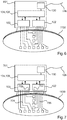
- FIG. 6 shows another level radar device.
- the measuring device 601 in turn has two operating modes, which can be activated automatically depending on external influences.
- the present example shows a reaction to a changed energy budget and / or changing temperature conditions. While in a state of sufficiently good energy supply the measuring device 601 can realize an operating mode according to the device 101, when the energy budget is reduced and / or an upper limit temperature is reached, the device can automatically switch to a second operating mode in which only a reduced number of RSOCs remains is used for the measurement.
- the control device 104 deactivates the second RSOC 103. The measurement then takes place exclusively with the first RSOC 102 and the antenna elements 110 to 112, 117 to 119.
- the energy consumption of the system is reduced significantly. It can also be provided, in a third operating mode, to control the radar chips 102, 103 alternately with the respectively connected transmitting and receiving elements in successive measuring cycles. By this measure, the heating the electronics are controlled and influenced.
- the evaluation circuit 106 communicates with the drive circuit 104 in order to optimize and adapt the evaluation of the signals in a suitable manner, depending on the selected operating mode.
- FIG. 7 illustrates again a particularly advantageous embodiment of a level radar device or sensor 701.
- the sensor has two standard RSOC's 102, 103, each with three transmission channels and four receiving channels.
- the use of these standard ICs produced in large numbers enables the cost-effective construction of a level measuring device 701.
- an antenna device 1130 which is optimized according to the system, it is possible to provide a first subset of the transmitting and / or receiving channels 704, 705 with the transmitting and receiving devices the antenna device 1130 to connect.
- the control device 104, 106 is configured to deactivate the unused transmitting and / or receiving channels 702, 703 of the radar chips 102, 103, ie to convert them into an energy-optimized state.
- the evaluation device 106 is set up to receive only a part of the data provided by the radar chips 702, 703 and / or to process only a part of the signals.
- the control device 104 is set up to activate only part of the transmission channels that can be activated in the radar chips during a measurement cycle. Energy can be saved by this measure.
- FIG. 8 shows a more advanced design.
- the device 801 is again characterized by the ability to change the operating and evaluation mode during runtime. It is provided to position the transmitting elements 109 to 112 at a distance dy 120 of less than or equal to half the wavelength of the radiated high-frequency signal. It may further be provided to make the propagation time of the high-frequency signal from the radar chips 102, 103 to the transmission elements 109 to 112 essentially the same for all transmission channels by inserting corresponding compensation structures 802, 803. It gets that way and Way possible to operate the meter 801 in a second mode of operation as a real-time beamformer in the transmission mode with analog beam shaping as a so-called phased array. At the receiving end, only one-dimensional digital beamforming becomes necessary.
- FIGS. 9A to 9D show a drive sequence for the two modes of operation.
- Diagrams 901 and 902 of FIG Figures 9A and 9B The control unit 104 first activates the first transmission channel of the radar chip 103.
- the signal emitted by the transmission unit 109 is received by the simultaneously operated reception channels of the radar chips, which are connected to the elements 113 to 119 , received and forwarded in digital form to the evaluation chip.
- the second transmission channel in the radar chip 103 is activated.
- the simultaneously received signals are in turn forwarded to the evaluation unit 106 and stored.
- the transmission element 111 is acted upon by the second radar chip 102 with transmission signals.
- the measurement data acquisition ends after passing through all the transmission channels used for the measurement.
- the evaluation unit 106 carries out a method for digital beamforming in two dimensions using those echo signals which are in communication with actually used transmitting and receiving elements.
- the method has the advantage that within the evaluation, any desired echo curves for predefinable angular directions can be digitally synthesized.
- the disadvantage is the high computational effort and the long measurement time.
- the flowcharts 903, 904 of Figures 9C and 9D clarify the necessary driving sequences.
- the operating mode is characterized in that, in contrast to the previously mentioned sequence at least two or advantageously all TX channels of the radar chips 102, 103 connected to transmit elements are activated simultaneously.
- a phase offset of the transmission signals can be selectively set with one another, as a result of which the resulting transmission signal is superimposed to a maximum in a predefined spatial direction (analog beamforming).
- the phase offset between the transmission channels is varied in successive measuring cycles.
- the method may be extended in time or shortened depending on the range of spatial directions to be detected.
- the reception stages of the radar chips 102, 103 connected to the reception elements 113 to 119 are activated, and transmit the acquired data to the evaluation unit.
- the evaluation unit 106 taking into account the currently set phase specifications for the transmission signals, performs one-dimensional digital beamforming for the reception signals, thereby beamforming in an angular direction which is substantially perpendicular to the angular direction of the beamforming by the transmission beamforming.
Landscapes
- Physics & Mathematics (AREA)
- Engineering & Computer Science (AREA)
- Radar, Positioning & Navigation (AREA)
- Remote Sensing (AREA)
- General Physics & Mathematics (AREA)
- Electromagnetism (AREA)
- Computer Networks & Wireless Communication (AREA)
- Thermal Sciences (AREA)
- Fluid Mechanics (AREA)
- Radar Systems Or Details Thereof (AREA)
Priority Applications (5)
| Application Number | Priority Date | Filing Date | Title |
|---|---|---|---|
| HUE17195233A HUE053290T2 (hu) | 2017-10-06 | 2017-10-06 | Radar töltöttségi szintet mérõ eszköz chipen |
| EP17195233.6A EP3467450B1 (fr) | 2017-10-06 | 2017-10-06 | Appareil de mesure de niveau de remplissage à radar pourvu d'un système radar sur puce |
| US16/143,208 US11326926B2 (en) | 2017-10-06 | 2018-09-26 | Radar fill level measurement device with a radar system-on-chip |
| CN201811167797.9A CN109632048B (zh) | 2017-10-06 | 2018-10-08 | 具有片上雷达系统的雷达物位测量装置 |
| US17/658,748 US12313438B2 (en) | 2017-10-06 | 2022-04-11 | Radar fill level measurement device with a radar system-on-chip |
Applications Claiming Priority (1)
| Application Number | Priority Date | Filing Date | Title |
|---|---|---|---|
| EP17195233.6A EP3467450B1 (fr) | 2017-10-06 | 2017-10-06 | Appareil de mesure de niveau de remplissage à radar pourvu d'un système radar sur puce |
Publications (2)
| Publication Number | Publication Date |
|---|---|
| EP3467450A1 true EP3467450A1 (fr) | 2019-04-10 |
| EP3467450B1 EP3467450B1 (fr) | 2020-12-09 |
Family
ID=60037486
Family Applications (1)
| Application Number | Title | Priority Date | Filing Date |
|---|---|---|---|
| EP17195233.6A Active EP3467450B1 (fr) | 2017-10-06 | 2017-10-06 | Appareil de mesure de niveau de remplissage à radar pourvu d'un système radar sur puce |
Country Status (4)
| Country | Link |
|---|---|
| US (2) | US11326926B2 (fr) |
| EP (1) | EP3467450B1 (fr) |
| CN (1) | CN109632048B (fr) |
| HU (1) | HUE053290T2 (fr) |
Cited By (7)
| Publication number | Priority date | Publication date | Assignee | Title |
|---|---|---|---|---|
| DE102019133245A1 (de) * | 2019-12-05 | 2021-06-10 | Endress+Hauser SE+Co. KG | Füllstandsmessgerät und Verfahren zur Radar-basierten Messung eines Füllstands |
| WO2022058102A1 (fr) * | 2020-09-17 | 2022-03-24 | Endress+Hauser SE+Co. KG | Dispositif de mesure de niveau de remplissage de résolution angulaire |
| WO2022089720A1 (fr) * | 2020-10-26 | 2022-05-05 | Vega Grieshaber Kg | Jauge de niveau à acquisition de topologie |
| EP4102195A1 (fr) * | 2021-06-10 | 2022-12-14 | VEGA Grieshaber KG | Dispositif de mesure de niveau de remplissage destiné à la surveillance de la topologie de surface d'une marchandise en vrac |
| US20240248192A1 (en) * | 2023-01-23 | 2024-07-25 | Vega Grieshaber Kg | Radar circuit |
| DE102023122776A1 (de) | 2023-08-24 | 2025-02-27 | Vega Grieshaber Kg | Verfahren zum Bestimmen eines Füllstands eines Füllguts in einem Behälter |
| US12487323B2 (en) | 2021-03-02 | 2025-12-02 | Vega Grieshaber Kg | Cascadable radar element with transmit antenna and receive antenna |
Families Citing this family (12)
| Publication number | Priority date | Publication date | Assignee | Title |
|---|---|---|---|---|
| DE102019219816A1 (de) * | 2019-12-17 | 2021-06-17 | Fresenius Medical Care Deutschland Gmbh | Vorrichtung zur Messung von Volumina einer Flüssigkeit in einem Behältnis mittels Messung einer abgegeben hochfrequenten Strahlung |
| GB202003332D0 (en) * | 2020-03-06 | 2020-04-22 | Johnson Matthey Plc | Level measurement apparatus |
| CN111721357B (zh) * | 2020-05-21 | 2025-07-25 | 北京锐达仪表有限公司 | 物料测量装置及物料测量系统 |
| WO2021254624A1 (fr) * | 2020-06-18 | 2021-12-23 | Vega Grieshaber Kg | Système d'antennes pour appareil de mesure radar à capture de topologie |
| EP4168755A1 (fr) * | 2020-06-18 | 2023-04-26 | VEGA Grieshaber KG | Radar de niveau de remplissage pour capture de niveau et de topologie |
| CN115917267A (zh) | 2020-07-20 | 2023-04-04 | Vega格里沙贝两合公司 | 自给式多维测量雷达传感器 |
| CN115867771A (zh) * | 2020-07-20 | 2023-03-28 | Vega格里沙贝两合公司 | 多维测量物位雷达和方法 |
| DE102021110820B3 (de) | 2021-04-28 | 2022-08-04 | Audi Aktiengesellschaft | Radarsensorvorrichtung, Radarsystem mit einer entsprechenden Radarsensorvorrichtung, Kraftfahrzeug, sowie je ein Verfahren zum Betreiben und Herstellen einer Radarsensorvorrichtung |
| DE102021115874A1 (de) * | 2021-06-18 | 2022-12-22 | Endress+Hauser SE+Co. KG | Füllstandsmessung |
| DE102021118496A1 (de) * | 2021-07-16 | 2023-01-19 | Endress+Hauser SE+Co. KG | Füllstandsmessgerät |
| US12429368B2 (en) | 2022-01-08 | 2025-09-30 | Honeywell International Inc. | Imaging radar level gauge with adaptive beam steering capability operating under harsh conditions |
| DE102022128063A1 (de) * | 2022-10-24 | 2024-04-25 | Endress+Hauser SE+Co. KG | Übertragung ortsaufgelöster Füllstandsmesswerte |
Citations (6)
| Publication number | Priority date | Publication date | Assignee | Title |
|---|---|---|---|---|
| US20020020216A1 (en) * | 2000-08-17 | 2002-02-21 | Daniel Schultheiss | Filling-level measuring device that evaluates echo signals |
| WO2002031450A1 (fr) * | 2000-10-10 | 2002-04-18 | Endress + Hauser Gmbh + Co. Kg | Appareil pour mesurer un niveau de remplissage |
| US20040119636A1 (en) * | 2002-12-20 | 2004-06-24 | Edvardsson Kurt Olov | Method and apparatus for radar-based level gauging |
| WO2010144936A1 (fr) * | 2009-06-17 | 2010-12-23 | Vatron Gmbh | Procédé et dispositif de calcul d'une surface d'un produit de remplissage d'un conteneur |
| US20150253176A1 (en) * | 2014-03-05 | 2015-09-10 | Rosemount Tank Radar Ab | Low power radar level gauge system |
| EP3171138A1 (fr) * | 2015-11-17 | 2017-05-24 | VEGA Grieshaber KG | Dispositif d'antenne et procédé d'envoi et/ou de réception d'un signal |
Family Cites Families (10)
| Publication number | Priority date | Publication date | Assignee | Title |
|---|---|---|---|---|
| US8421588B1 (en) * | 2004-06-23 | 2013-04-16 | Wireless Telematics Llc | Combination wireless electrical apparatus controller and energy monitoring device and method of use |
| CN2788151Y (zh) * | 2005-01-06 | 2006-06-14 | 黑龙江省中贝技术有限公司 | 多通道主从式核物位监测装置 |
| CN110251769B (zh) * | 2007-12-31 | 2022-04-01 | 德卡产品有限公司 | 输注泵组件 |
| US7701385B2 (en) * | 2008-05-22 | 2010-04-20 | Rosemount Tank Radar Ab | Multi-channel radar level gauge system |
| CN102460218A (zh) * | 2009-06-16 | 2012-05-16 | 住友大阪水泥股份有限公司 | 构造物中的水的检测方法及构造物用部件及构造物中的水的检测装置 |
| CN103261852B (zh) * | 2010-12-16 | 2015-07-15 | Vega格里沙贝两合公司 | 用于物位测量的测量装置、控制装置和测量仪器 |
| CN104755175B (zh) * | 2012-10-25 | 2017-09-08 | 固瑞克明尼苏达有限公司 | 热熔液位传感器和传感器壳体 |
| CN102983415A (zh) * | 2012-12-10 | 2013-03-20 | 西安电子工程研究所 | 一种用于物位多点测量雷达的收发天线系统 |
| EP2803952B1 (fr) | 2013-05-17 | 2019-07-10 | VEGA Grieshaber KG | Commande d'appareil de mesure pour la détermination de la topologie d'une surface d'un matériau en vrac |
| US10948332B2 (en) * | 2016-11-11 | 2021-03-16 | Rosemount Tank Radar Ab | Radar level gauge with disconnection of energy store |
-
2017
- 2017-10-06 HU HUE17195233A patent/HUE053290T2/hu unknown
- 2017-10-06 EP EP17195233.6A patent/EP3467450B1/fr active Active
-
2018
- 2018-09-26 US US16/143,208 patent/US11326926B2/en active Active
- 2018-10-08 CN CN201811167797.9A patent/CN109632048B/zh active Active
-
2022
- 2022-04-11 US US17/658,748 patent/US12313438B2/en active Active
Patent Citations (6)
| Publication number | Priority date | Publication date | Assignee | Title |
|---|---|---|---|---|
| US20020020216A1 (en) * | 2000-08-17 | 2002-02-21 | Daniel Schultheiss | Filling-level measuring device that evaluates echo signals |
| WO2002031450A1 (fr) * | 2000-10-10 | 2002-04-18 | Endress + Hauser Gmbh + Co. Kg | Appareil pour mesurer un niveau de remplissage |
| US20040119636A1 (en) * | 2002-12-20 | 2004-06-24 | Edvardsson Kurt Olov | Method and apparatus for radar-based level gauging |
| WO2010144936A1 (fr) * | 2009-06-17 | 2010-12-23 | Vatron Gmbh | Procédé et dispositif de calcul d'une surface d'un produit de remplissage d'un conteneur |
| US20150253176A1 (en) * | 2014-03-05 | 2015-09-10 | Rosemount Tank Radar Ab | Low power radar level gauge system |
| EP3171138A1 (fr) * | 2015-11-17 | 2017-05-24 | VEGA Grieshaber KG | Dispositif d'antenne et procédé d'envoi et/ou de réception d'un signal |
Cited By (8)
| Publication number | Priority date | Publication date | Assignee | Title |
|---|---|---|---|---|
| DE102019133245A1 (de) * | 2019-12-05 | 2021-06-10 | Endress+Hauser SE+Co. KG | Füllstandsmessgerät und Verfahren zur Radar-basierten Messung eines Füllstands |
| DE102019133245B4 (de) * | 2019-12-05 | 2021-06-24 | Endress+Hauser SE+Co. KG | Füllstandsmessgerät und Verfahren zur Radar-basierten Messung eines Füllstands |
| WO2022058102A1 (fr) * | 2020-09-17 | 2022-03-24 | Endress+Hauser SE+Co. KG | Dispositif de mesure de niveau de remplissage de résolution angulaire |
| WO2022089720A1 (fr) * | 2020-10-26 | 2022-05-05 | Vega Grieshaber Kg | Jauge de niveau à acquisition de topologie |
| US12487323B2 (en) | 2021-03-02 | 2025-12-02 | Vega Grieshaber Kg | Cascadable radar element with transmit antenna and receive antenna |
| EP4102195A1 (fr) * | 2021-06-10 | 2022-12-14 | VEGA Grieshaber KG | Dispositif de mesure de niveau de remplissage destiné à la surveillance de la topologie de surface d'une marchandise en vrac |
| US20240248192A1 (en) * | 2023-01-23 | 2024-07-25 | Vega Grieshaber Kg | Radar circuit |
| DE102023122776A1 (de) | 2023-08-24 | 2025-02-27 | Vega Grieshaber Kg | Verfahren zum Bestimmen eines Füllstands eines Füllguts in einem Behälter |
Also Published As
| Publication number | Publication date |
|---|---|
| EP3467450B1 (fr) | 2020-12-09 |
| US12313438B2 (en) | 2025-05-27 |
| US20220236096A1 (en) | 2022-07-28 |
| CN109632048B (zh) | 2022-07-26 |
| CN109632048A (zh) | 2019-04-16 |
| US20190107426A1 (en) | 2019-04-11 |
| HUE053290T2 (hu) | 2021-06-28 |
| US11326926B2 (en) | 2022-05-10 |
Similar Documents
| Publication | Publication Date | Title |
|---|---|---|
| EP3467450B1 (fr) | Appareil de mesure de niveau de remplissage à radar pourvu d'un système radar sur puce | |
| EP1570291B1 (fr) | Procede et dispositif pour des mesures radar de distance proche multistatiques | |
| EP3467447B1 (fr) | Appareil de mesure de niveau de remplissage à une pluralité des chips radar | |
| EP1340097B1 (fr) | Dispositif radar et son procede de fonctionnement | |
| WO2017148561A1 (fr) | Système de radar, comportant un ensemble d'antennes pour émettre et recevoir un rayonnement électromagnétique | |
| DE102007038629B4 (de) | Radarvorrichtung im Kraftfahrzeug | |
| EP3794369A1 (fr) | Procédé pour l'étalonnage de phases de composants haute fréquence d'un capteur radar | |
| EP2775273B1 (fr) | Radar multi-systèmes pour la mesure du niveau de remplissage | |
| DE102010002759B4 (de) | Radarsensor mit Selbsttesteinrichtung | |
| EP2331917A1 (fr) | Appareil de mesure de niveau fonctionnant à micro-ondes | |
| EP3692343B1 (fr) | Jauge de niveau avec système radar | |
| DE10049995A1 (de) | Füllstandsmessgerät | |
| DE102020115709B3 (de) | Automobilradaranordnung und verfahren zur objektdetektion durch ein fahrzeugradar | |
| DE102018206701A1 (de) | Überwachen eines FMCW-Radarsensors | |
| EP2550544A1 (fr) | Dispositif d'assistance au conducteur pour un véhicule et procédé pour faire fonctionner un appareil radar | |
| EP1434974B1 (fr) | Dispositif et procédé pour determiner le niveau de remplissage d'une substance dans un contenant | |
| EP2126604A1 (fr) | Dispositif de mesure de distance | |
| EP3575755B1 (fr) | Appareil de mesure de niveau de remplissage à commande d'antenne optimisée et méthode de mesure de niveau | |
| DE102019131677A1 (de) | Phasenmessung in einem radar-system | |
| DE102006017007B4 (de) | Impulsradarvorrichtung für Fahrzeuge | |
| WO2020225314A1 (fr) | Système de radar multistatique cohérent, en particulier pour une utilisation dans un véhicule | |
| EP3171291B1 (fr) | Procédé et dispositif d'interrogation de données provenant d'un élément passif | |
| WO2022129005A1 (fr) | Ligne à retard à fibre optique programmable | |
| WO2009077236A1 (fr) | Détecteur radar monostatique multifaisceau, et procédé | |
| EP1969394A1 (fr) | Dispositif radar |
Legal Events
| Date | Code | Title | Description |
|---|---|---|---|
| PUAI | Public reference made under article 153(3) epc to a published international application that has entered the european phase |
Free format text: ORIGINAL CODE: 0009012 |
|
| STAA | Information on the status of an ep patent application or granted ep patent |
Free format text: STATUS: REQUEST FOR EXAMINATION WAS MADE |
|
| STAA | Information on the status of an ep patent application or granted ep patent |
Free format text: STATUS: EXAMINATION IS IN PROGRESS |
|
| 17P | Request for examination filed |
Effective date: 20181023 |
|
| AK | Designated contracting states |
Kind code of ref document: A1 Designated state(s): AL AT BE BG CH CY CZ DE DK EE ES FI FR GB GR HR HU IE IS IT LI LT LU LV MC MK MT NL NO PL PT RO RS SE SI SK SM TR |
|
| AX | Request for extension of the european patent |
Extension state: BA ME |
|
| 17Q | First examination report despatched |
Effective date: 20190327 |
|
| REG | Reference to a national code |
Ref country code: DE Ref legal event code: R079 Ref document number: 502017008559 Country of ref document: DE Free format text: PREVIOUS MAIN CLASS: G01F0023284000 Ipc: G01S0007030000 |
|
| RIC1 | Information provided on ipc code assigned before grant |
Ipc: G01S 7/03 20060101AFI20191203BHEP Ipc: G01S 13/88 20060101ALI20191203BHEP Ipc: G01S 13/42 20060101ALI20191203BHEP Ipc: G01F 22/00 20060101ALI20191203BHEP Ipc: G01F 23/284 20060101ALI20191203BHEP Ipc: G01S 7/35 20060101ALI20191203BHEP |
|
| GRAP | Despatch of communication of intention to grant a patent |
Free format text: ORIGINAL CODE: EPIDOSNIGR1 |
|
| STAA | Information on the status of an ep patent application or granted ep patent |
Free format text: STATUS: GRANT OF PATENT IS INTENDED |
|
| INTG | Intention to grant announced |
Effective date: 20200612 |
|
| GRAS | Grant fee paid |
Free format text: ORIGINAL CODE: EPIDOSNIGR3 |
|
| GRAA | (expected) grant |
Free format text: ORIGINAL CODE: 0009210 |
|
| STAA | Information on the status of an ep patent application or granted ep patent |
Free format text: STATUS: THE PATENT HAS BEEN GRANTED |
|
| AK | Designated contracting states |
Kind code of ref document: B1 Designated state(s): AL AT BE BG CH CY CZ DE DK EE ES FI FR GB GR HR HU IE IS IT LI LT LU LV MC MK MT NL NO PL PT RO RS SE SI SK SM TR |
|
| REG | Reference to a national code |
Ref country code: GB Ref legal event code: FG4D Free format text: NOT ENGLISH |
|
| REG | Reference to a national code |
Ref country code: AT Ref legal event code: REF Ref document number: 1343987 Country of ref document: AT Kind code of ref document: T Effective date: 20201215 Ref country code: CH Ref legal event code: EP |
|
| REG | Reference to a national code |
Ref country code: DE Ref legal event code: R096 Ref document number: 502017008559 Country of ref document: DE |
|
| REG | Reference to a national code |
Ref country code: IE Ref legal event code: FG4D Free format text: LANGUAGE OF EP DOCUMENT: GERMAN |
|
| REG | Reference to a national code |
Ref country code: SE Ref legal event code: TRGR |
|
| REG | Reference to a national code |
Ref country code: NL Ref legal event code: FP |
|
| PG25 | Lapsed in a contracting state [announced via postgrant information from national office to epo] |
Ref country code: NO Free format text: LAPSE BECAUSE OF FAILURE TO SUBMIT A TRANSLATION OF THE DESCRIPTION OR TO PAY THE FEE WITHIN THE PRESCRIBED TIME-LIMIT Effective date: 20210309 Ref country code: RS Free format text: LAPSE BECAUSE OF FAILURE TO SUBMIT A TRANSLATION OF THE DESCRIPTION OR TO PAY THE FEE WITHIN THE PRESCRIBED TIME-LIMIT Effective date: 20201209 Ref country code: GR Free format text: LAPSE BECAUSE OF FAILURE TO SUBMIT A TRANSLATION OF THE DESCRIPTION OR TO PAY THE FEE WITHIN THE PRESCRIBED TIME-LIMIT Effective date: 20210310 Ref country code: FI Free format text: LAPSE BECAUSE OF FAILURE TO SUBMIT A TRANSLATION OF THE DESCRIPTION OR TO PAY THE FEE WITHIN THE PRESCRIBED TIME-LIMIT Effective date: 20201209 |
|
| PG25 | Lapsed in a contracting state [announced via postgrant information from national office to epo] |
Ref country code: BG Free format text: LAPSE BECAUSE OF FAILURE TO SUBMIT A TRANSLATION OF THE DESCRIPTION OR TO PAY THE FEE WITHIN THE PRESCRIBED TIME-LIMIT Effective date: 20210309 Ref country code: LV Free format text: LAPSE BECAUSE OF FAILURE TO SUBMIT A TRANSLATION OF THE DESCRIPTION OR TO PAY THE FEE WITHIN THE PRESCRIBED TIME-LIMIT Effective date: 20201209 |
|
| REG | Reference to a national code |
Ref country code: HU Ref legal event code: AG4A Ref document number: E053290 Country of ref document: HU |
|
| PG25 | Lapsed in a contracting state [announced via postgrant information from national office to epo] |
Ref country code: HR Free format text: LAPSE BECAUSE OF FAILURE TO SUBMIT A TRANSLATION OF THE DESCRIPTION OR TO PAY THE FEE WITHIN THE PRESCRIBED TIME-LIMIT Effective date: 20201209 |
|
| REG | Reference to a national code |
Ref country code: LT Ref legal event code: MG9D |
|
| PG25 | Lapsed in a contracting state [announced via postgrant information from national office to epo] |
Ref country code: SK Free format text: LAPSE BECAUSE OF FAILURE TO SUBMIT A TRANSLATION OF THE DESCRIPTION OR TO PAY THE FEE WITHIN THE PRESCRIBED TIME-LIMIT Effective date: 20201209 Ref country code: RO Free format text: LAPSE BECAUSE OF FAILURE TO SUBMIT A TRANSLATION OF THE DESCRIPTION OR TO PAY THE FEE WITHIN THE PRESCRIBED TIME-LIMIT Effective date: 20201209 Ref country code: PT Free format text: LAPSE BECAUSE OF FAILURE TO SUBMIT A TRANSLATION OF THE DESCRIPTION OR TO PAY THE FEE WITHIN THE PRESCRIBED TIME-LIMIT Effective date: 20210409 Ref country code: SM Free format text: LAPSE BECAUSE OF FAILURE TO SUBMIT A TRANSLATION OF THE DESCRIPTION OR TO PAY THE FEE WITHIN THE PRESCRIBED TIME-LIMIT Effective date: 20201209 Ref country code: EE Free format text: LAPSE BECAUSE OF FAILURE TO SUBMIT A TRANSLATION OF THE DESCRIPTION OR TO PAY THE FEE WITHIN THE PRESCRIBED TIME-LIMIT Effective date: 20201209 Ref country code: CZ Free format text: LAPSE BECAUSE OF FAILURE TO SUBMIT A TRANSLATION OF THE DESCRIPTION OR TO PAY THE FEE WITHIN THE PRESCRIBED TIME-LIMIT Effective date: 20201209 Ref country code: LT Free format text: LAPSE BECAUSE OF FAILURE TO SUBMIT A TRANSLATION OF THE DESCRIPTION OR TO PAY THE FEE WITHIN THE PRESCRIBED TIME-LIMIT Effective date: 20201209 |
|
| PG25 | Lapsed in a contracting state [announced via postgrant information from national office to epo] |
Ref country code: PL Free format text: LAPSE BECAUSE OF FAILURE TO SUBMIT A TRANSLATION OF THE DESCRIPTION OR TO PAY THE FEE WITHIN THE PRESCRIBED TIME-LIMIT Effective date: 20201209 |
|
| REG | Reference to a national code |
Ref country code: DE Ref legal event code: R097 Ref document number: 502017008559 Country of ref document: DE |
|
| PG25 | Lapsed in a contracting state [announced via postgrant information from national office to epo] |
Ref country code: IS Free format text: LAPSE BECAUSE OF FAILURE TO SUBMIT A TRANSLATION OF THE DESCRIPTION OR TO PAY THE FEE WITHIN THE PRESCRIBED TIME-LIMIT Effective date: 20210409 |
|
| PLBE | No opposition filed within time limit |
Free format text: ORIGINAL CODE: 0009261 |
|
| STAA | Information on the status of an ep patent application or granted ep patent |
Free format text: STATUS: NO OPPOSITION FILED WITHIN TIME LIMIT |
|
| PG25 | Lapsed in a contracting state [announced via postgrant information from national office to epo] |
Ref country code: IT Free format text: LAPSE BECAUSE OF FAILURE TO SUBMIT A TRANSLATION OF THE DESCRIPTION OR TO PAY THE FEE WITHIN THE PRESCRIBED TIME-LIMIT Effective date: 20201209 Ref country code: AL Free format text: LAPSE BECAUSE OF FAILURE TO SUBMIT A TRANSLATION OF THE DESCRIPTION OR TO PAY THE FEE WITHIN THE PRESCRIBED TIME-LIMIT Effective date: 20201209 |
|
| 26N | No opposition filed |
Effective date: 20210910 |
|
| PG25 | Lapsed in a contracting state [announced via postgrant information from national office to epo] |
Ref country code: DK Free format text: LAPSE BECAUSE OF FAILURE TO SUBMIT A TRANSLATION OF THE DESCRIPTION OR TO PAY THE FEE WITHIN THE PRESCRIBED TIME-LIMIT Effective date: 20201209 Ref country code: SI Free format text: LAPSE BECAUSE OF FAILURE TO SUBMIT A TRANSLATION OF THE DESCRIPTION OR TO PAY THE FEE WITHIN THE PRESCRIBED TIME-LIMIT Effective date: 20201209 |
|
| PG25 | Lapsed in a contracting state [announced via postgrant information from national office to epo] |
Ref country code: ES Free format text: LAPSE BECAUSE OF FAILURE TO SUBMIT A TRANSLATION OF THE DESCRIPTION OR TO PAY THE FEE WITHIN THE PRESCRIBED TIME-LIMIT Effective date: 20201209 |
|
| REG | Reference to a national code |
Ref country code: CH Ref legal event code: PL |
|
| PG25 | Lapsed in a contracting state [announced via postgrant information from national office to epo] |
Ref country code: IS Free format text: LAPSE BECAUSE OF FAILURE TO SUBMIT A TRANSLATION OF THE DESCRIPTION OR TO PAY THE FEE WITHIN THE PRESCRIBED TIME-LIMIT Effective date: 20210409 |
|
| REG | Reference to a national code |
Ref country code: BE Ref legal event code: MM Effective date: 20211031 |
|
| PG25 | Lapsed in a contracting state [announced via postgrant information from national office to epo] |
Ref country code: MC Free format text: LAPSE BECAUSE OF FAILURE TO SUBMIT A TRANSLATION OF THE DESCRIPTION OR TO PAY THE FEE WITHIN THE PRESCRIBED TIME-LIMIT Effective date: 20201209 |
|
| PG25 | Lapsed in a contracting state [announced via postgrant information from national office to epo] |
Ref country code: LU Free format text: LAPSE BECAUSE OF NON-PAYMENT OF DUE FEES Effective date: 20211006 Ref country code: BE Free format text: LAPSE BECAUSE OF NON-PAYMENT OF DUE FEES Effective date: 20211031 |
|
| PG25 | Lapsed in a contracting state [announced via postgrant information from national office to epo] |
Ref country code: LI Free format text: LAPSE BECAUSE OF NON-PAYMENT OF DUE FEES Effective date: 20211031 Ref country code: CH Free format text: LAPSE BECAUSE OF NON-PAYMENT OF DUE FEES Effective date: 20211031 |
|
| PG25 | Lapsed in a contracting state [announced via postgrant information from national office to epo] |
Ref country code: IE Free format text: LAPSE BECAUSE OF NON-PAYMENT OF DUE FEES Effective date: 20211006 |
|
| P01 | Opt-out of the competence of the unified patent court (upc) registered |
Effective date: 20230508 |
|
| PG25 | Lapsed in a contracting state [announced via postgrant information from national office to epo] |
Ref country code: CY Free format text: LAPSE BECAUSE OF FAILURE TO SUBMIT A TRANSLATION OF THE DESCRIPTION OR TO PAY THE FEE WITHIN THE PRESCRIBED TIME-LIMIT Effective date: 20201209 |
|
| REG | Reference to a national code |
Ref country code: AT Ref legal event code: MM01 Ref document number: 1343987 Country of ref document: AT Kind code of ref document: T Effective date: 20221006 |
|
| PG25 | Lapsed in a contracting state [announced via postgrant information from national office to epo] |
Ref country code: AT Free format text: LAPSE BECAUSE OF NON-PAYMENT OF DUE FEES Effective date: 20221006 |
|
| PG25 | Lapsed in a contracting state [announced via postgrant information from national office to epo] |
Ref country code: MK Free format text: LAPSE BECAUSE OF FAILURE TO SUBMIT A TRANSLATION OF THE DESCRIPTION OR TO PAY THE FEE WITHIN THE PRESCRIBED TIME-LIMIT Effective date: 20201209 |
|
| PG25 | Lapsed in a contracting state [announced via postgrant information from national office to epo] |
Ref country code: TR Free format text: LAPSE BECAUSE OF FAILURE TO SUBMIT A TRANSLATION OF THE DESCRIPTION OR TO PAY THE FEE WITHIN THE PRESCRIBED TIME-LIMIT Effective date: 20201209 |
|
| PG25 | Lapsed in a contracting state [announced via postgrant information from national office to epo] |
Ref country code: MT Free format text: LAPSE BECAUSE OF FAILURE TO SUBMIT A TRANSLATION OF THE DESCRIPTION OR TO PAY THE FEE WITHIN THE PRESCRIBED TIME-LIMIT Effective date: 20201209 |
|
| PGFP | Annual fee paid to national office [announced via postgrant information from national office to epo] |
Ref country code: HU Payment date: 20250930 Year of fee payment: 9 |
|
| PGFP | Annual fee paid to national office [announced via postgrant information from national office to epo] |
Ref country code: NL Payment date: 20251023 Year of fee payment: 9 |
|
| PGFP | Annual fee paid to national office [announced via postgrant information from national office to epo] |
Ref country code: DE Payment date: 20251020 Year of fee payment: 9 |
|
| PGFP | Annual fee paid to national office [announced via postgrant information from national office to epo] |
Ref country code: GB Payment date: 20251024 Year of fee payment: 9 |
|
| PGFP | Annual fee paid to national office [announced via postgrant information from national office to epo] |
Ref country code: FR Payment date: 20251022 Year of fee payment: 9 |
|
| PGFP | Annual fee paid to national office [announced via postgrant information from national office to epo] |
Ref country code: SE Payment date: 20251023 Year of fee payment: 9 |