EP3467517B1 - Appareil de mesure de la direction du vent et de la vitesse du vent pour une éolienne ainsi que dispositif et procédé permettant de commander l'angle de lacet d'une éolienne à l'aide de ce dernier - Google Patents
Appareil de mesure de la direction du vent et de la vitesse du vent pour une éolienne ainsi que dispositif et procédé permettant de commander l'angle de lacet d'une éolienne à l'aide de ce dernier Download PDFInfo
- Publication number
- EP3467517B1 EP3467517B1 EP17848949.8A EP17848949A EP3467517B1 EP 3467517 B1 EP3467517 B1 EP 3467517B1 EP 17848949 A EP17848949 A EP 17848949A EP 3467517 B1 EP3467517 B1 EP 3467517B1
- Authority
- EP
- European Patent Office
- Prior art keywords
- wind
- velocity
- yaw angle
- anemometer
- ultrasonic wave
- Prior art date
- Legal status (The legal status is an assumption and is not a legal conclusion. Google has not performed a legal analysis and makes no representation as to the accuracy of the status listed.)
- Active
Links
Images


Classifications
-
- G—PHYSICS
- G01—MEASURING; TESTING
- G01P—MEASURING LINEAR OR ANGULAR SPEED, ACCELERATION, DECELERATION, OR SHOCK; INDICATING PRESENCE, ABSENCE, OR DIRECTION, OF MOVEMENT
- G01P5/00—Measuring speed of fluids, e.g. of air stream; Measuring speed of bodies relative to fluids, e.g. of ship, of aircraft
- G01P5/24—Measuring speed of fluids, e.g. of air stream; Measuring speed of bodies relative to fluids, e.g. of ship, of aircraft by measuring the direct influence of the streaming fluid on the properties of a detecting acoustical wave
- G01P5/241—Measuring speed of fluids, e.g. of air stream; Measuring speed of bodies relative to fluids, e.g. of ship, of aircraft by measuring the direct influence of the streaming fluid on the properties of a detecting acoustical wave by using reflection of acoustical waves, i.e. Doppler-effect
- G01P5/242—Measuring speed of fluids, e.g. of air stream; Measuring speed of bodies relative to fluids, e.g. of ship, of aircraft by measuring the direct influence of the streaming fluid on the properties of a detecting acoustical wave by using reflection of acoustical waves, i.e. Doppler-effect involving continuous, e.g. modulated or unmodulated, waves
-
- F—MECHANICAL ENGINEERING; LIGHTING; HEATING; WEAPONS; BLASTING
- F03—MACHINES OR ENGINES FOR LIQUIDS; WIND, SPRING, OR WEIGHT MOTORS; PRODUCING MECHANICAL POWER OR A REACTIVE PROPULSIVE THRUST, NOT OTHERWISE PROVIDED FOR
- F03D—WIND MOTORS
- F03D17/00—Monitoring or testing of wind motors, e.g. diagnostics
-
- F—MECHANICAL ENGINEERING; LIGHTING; HEATING; WEAPONS; BLASTING
- F03—MACHINES OR ENGINES FOR LIQUIDS; WIND, SPRING, OR WEIGHT MOTORS; PRODUCING MECHANICAL POWER OR A REACTIVE PROPULSIVE THRUST, NOT OTHERWISE PROVIDED FOR
- F03D—WIND MOTORS
- F03D1/00—Wind motors with rotation axis substantially parallel to the air flow entering the rotor
-
- F—MECHANICAL ENGINEERING; LIGHTING; HEATING; WEAPONS; BLASTING
- F03—MACHINES OR ENGINES FOR LIQUIDS; WIND, SPRING, OR WEIGHT MOTORS; PRODUCING MECHANICAL POWER OR A REACTIVE PROPULSIVE THRUST, NOT OTHERWISE PROVIDED FOR
- F03D—WIND MOTORS
- F03D7/00—Controlling wind motors
- F03D7/02—Controlling wind motors the wind motors having rotation axis substantially parallel to the air flow entering the rotor
- F03D7/0204—Controlling wind motors the wind motors having rotation axis substantially parallel to the air flow entering the rotor for orientation in relation to wind direction
-
- F—MECHANICAL ENGINEERING; LIGHTING; HEATING; WEAPONS; BLASTING
- F03—MACHINES OR ENGINES FOR LIQUIDS; WIND, SPRING, OR WEIGHT MOTORS; PRODUCING MECHANICAL POWER OR A REACTIVE PROPULSIVE THRUST, NOT OTHERWISE PROVIDED FOR
- F03D—WIND MOTORS
- F03D7/00—Controlling wind motors
- F03D7/02—Controlling wind motors the wind motors having rotation axis substantially parallel to the air flow entering the rotor
- F03D7/022—Adjusting aerodynamic properties of the blades
- F03D7/0224—Adjusting blade pitch
-
- G—PHYSICS
- G01—MEASURING; TESTING
- G01P—MEASURING LINEAR OR ANGULAR SPEED, ACCELERATION, DECELERATION, OR SHOCK; INDICATING PRESENCE, ABSENCE, OR DIRECTION, OF MOVEMENT
- G01P13/00—Indicating or recording presence, absence, or direction, of movement
- G01P13/02—Indicating direction only, e.g. by weather vane
- G01P13/04—Indicating positive or negative direction of a linear movement or clockwise or anti-clockwise direction of a rotational movement
- G01P13/045—Indicating positive or negative direction of a linear movement or clockwise or anti-clockwise direction of a rotational movement with speed indication
-
- G—PHYSICS
- G01—MEASURING; TESTING
- G01P—MEASURING LINEAR OR ANGULAR SPEED, ACCELERATION, DECELERATION, OR SHOCK; INDICATING PRESENCE, ABSENCE, OR DIRECTION, OF MOVEMENT
- G01P5/00—Measuring speed of fluids, e.g. of air stream; Measuring speed of bodies relative to fluids, e.g. of ship, of aircraft
- G01P5/02—Measuring speed of fluids, e.g. of air stream; Measuring speed of bodies relative to fluids, e.g. of ship, of aircraft by measuring forces exerted by the fluid on solid bodies, e.g. anemometer
-
- G—PHYSICS
- G01—MEASURING; TESTING
- G01P—MEASURING LINEAR OR ANGULAR SPEED, ACCELERATION, DECELERATION, OR SHOCK; INDICATING PRESENCE, ABSENCE, OR DIRECTION, OF MOVEMENT
- G01P5/00—Measuring speed of fluids, e.g. of air stream; Measuring speed of bodies relative to fluids, e.g. of ship, of aircraft
- G01P5/24—Measuring speed of fluids, e.g. of air stream; Measuring speed of bodies relative to fluids, e.g. of ship, of aircraft by measuring the direct influence of the streaming fluid on the properties of a detecting acoustical wave
-
- F—MECHANICAL ENGINEERING; LIGHTING; HEATING; WEAPONS; BLASTING
- F05—INDEXING SCHEMES RELATING TO ENGINES OR PUMPS IN VARIOUS SUBCLASSES OF CLASSES F01-F04
- F05B—INDEXING SCHEME RELATING TO WIND, SPRING, WEIGHT, INERTIA OR LIKE MOTORS, TO MACHINES OR ENGINES FOR LIQUIDS COVERED BY SUBCLASSES F03B, F03D AND F03G
- F05B2270/00—Control
- F05B2270/30—Control parameters, e.g. input parameters
- F05B2270/32—Wind speeds
-
- F—MECHANICAL ENGINEERING; LIGHTING; HEATING; WEAPONS; BLASTING
- F05—INDEXING SCHEMES RELATING TO ENGINES OR PUMPS IN VARIOUS SUBCLASSES OF CLASSES F01-F04
- F05B—INDEXING SCHEME RELATING TO WIND, SPRING, WEIGHT, INERTIA OR LIKE MOTORS, TO MACHINES OR ENGINES FOR LIQUIDS COVERED BY SUBCLASSES F03B, F03D AND F03G
- F05B2270/00—Control
- F05B2270/30—Control parameters, e.g. input parameters
- F05B2270/321—Wind directions
-
- F—MECHANICAL ENGINEERING; LIGHTING; HEATING; WEAPONS; BLASTING
- F05—INDEXING SCHEMES RELATING TO ENGINES OR PUMPS IN VARIOUS SUBCLASSES OF CLASSES F01-F04
- F05B—INDEXING SCHEME RELATING TO WIND, SPRING, WEIGHT, INERTIA OR LIKE MOTORS, TO MACHINES OR ENGINES FOR LIQUIDS COVERED BY SUBCLASSES F03B, F03D AND F03G
- F05B2270/00—Control
- F05B2270/30—Control parameters, e.g. input parameters
- F05B2270/328—Blade pitch angle
-
- F—MECHANICAL ENGINEERING; LIGHTING; HEATING; WEAPONS; BLASTING
- F05—INDEXING SCHEMES RELATING TO ENGINES OR PUMPS IN VARIOUS SUBCLASSES OF CLASSES F01-F04
- F05B—INDEXING SCHEME RELATING TO WIND, SPRING, WEIGHT, INERTIA OR LIKE MOTORS, TO MACHINES OR ENGINES FOR LIQUIDS COVERED BY SUBCLASSES F03B, F03D AND F03G
- F05B2270/00—Control
- F05B2270/30—Control parameters, e.g. input parameters
- F05B2270/329—Azimuth or yaw angle
-
- F—MECHANICAL ENGINEERING; LIGHTING; HEATING; WEAPONS; BLASTING
- F05—INDEXING SCHEMES RELATING TO ENGINES OR PUMPS IN VARIOUS SUBCLASSES OF CLASSES F01-F04
- F05B—INDEXING SCHEME RELATING TO WIND, SPRING, WEIGHT, INERTIA OR LIKE MOTORS, TO MACHINES OR ENGINES FOR LIQUIDS COVERED BY SUBCLASSES F03B, F03D AND F03G
- F05B2270/00—Control
- F05B2270/80—Devices generating input signals, e.g. transducers, sensors, cameras or strain gauges
-
- Y—GENERAL TAGGING OF NEW TECHNOLOGICAL DEVELOPMENTS; GENERAL TAGGING OF CROSS-SECTIONAL TECHNOLOGIES SPANNING OVER SEVERAL SECTIONS OF THE IPC; TECHNICAL SUBJECTS COVERED BY FORMER USPC CROSS-REFERENCE ART COLLECTIONS [XRACs] AND DIGESTS
- Y02—TECHNOLOGIES OR APPLICATIONS FOR MITIGATION OR ADAPTATION AGAINST CLIMATE CHANGE
- Y02E—REDUCTION OF GREENHOUSE GAS [GHG] EMISSIONS, RELATED TO ENERGY GENERATION, TRANSMISSION OR DISTRIBUTION
- Y02E10/00—Energy generation through renewable energy sources
- Y02E10/70—Wind energy
- Y02E10/72—Wind turbines with rotation axis in wind direction
Definitions
- the present disclosure relates to an anemometer for a wind turbine in accordance with the preamble of claim 1.
- Such anemometer is disclosed in EP 2 048 507 A2 , EP 1 733 241 A1 and in TROELS FRIIES PEDERSEN ET AL: "Optimization of Wind Turbine Operation by Use of Spinner Anemometer Participation in IEA Task 29: Full Scale Wind Turbine Aero -dynamics, -elasticity and -acoustics.
- View project Research on Vertical-Axis Wind Turbines (VAWT) View project DENMARK. FORSKNINGSCENTER RISOE. RISOE-R, 30 August 2008, XP055631535, DK, ISSN: 0106-2840 .
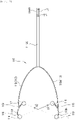
- a wind turbine is a device which generates electricity by disposing a rotating blade to be opposite to a wind blowing direction.
- a wind turbine of the related art includes a vertical axis 11, a nacelle 12 equipped at an upper portion of the vertical axis 11, a plurality of rotating blades 13 equipped at a front side of the nacelle 12, and a hub 14 which forms a rotation center of the plurality of rotating blades 13. Therefore, when the rotating blades 13 rotate by the wind, a rotary shaft of the hub 14 rotates together to generate electricity from the nacelle 12.
- an anemometer 15 which measures a wind velocity and a wind direction is installed to be vertical to an upper surface of a cover of a nacelle 12.
- An object to be achieved by the present disclosure is to provide an anemometer for a wind turbine which is capable of precisely measuring a wind velocity and a wind direction.
- Another object to be achieved by the present disclosure is to provide an apparatus and a method for controlling a yaw angle of a wind turbine which dispose a rotating blade to be opposite to a wind blowing direction to precisely measure a wind velocity and a wind direction, thereby improving an efficiency of electricity generation.
- an anemometer for a wind turbine is used for a wind turbine including a plurality of rotating blades and a hub which is equipped at a rotation center of the plurality of rotating blades and has a nosecone (in other words, a spinner) and is configured to be equipped in the nosecone.
- the anemometer for a wind turbine includes: a first ultrasonic sensor which oscillates a first ultrasonic wave and receives a second ultrasonic wave; a second ultrasonic sensor which oscillates the second ultrasonic wave and receives the first ultrasonic wave; a third ultrasonic sensor which oscillates a third ultrasonic wave in a first direction intersecting the first ultrasonic wave and receives a fourth ultrasonic wave in a second direction opposing to the first direction; and a fourth ultrasonic sensor which oscillates the fourth ultrasonic wave in the second direction and receives the third ultrasonic wave in the first direction, in which the first and second ultrasonic sensors measure a first wind velocity in the same direction as the transmitting direction of the first ultrasonic wave and the third and fourth ultrasonic sensors measure a second wind velocity in the same direction as the transmitting direction of the third ultrasonic wave.
- the anemometer may further include a support unit which supports the first, second, third, and fourth ultrasonic sensors to the nosecone and the first, second, third, and fourth ultrasonic sensors, the support unit, and a rotary shaft of the hub are disposed on one plane.
- the support unit may include a center support shaft which is configured to be equipped in the nosecone to be disposed to coincide with an axial direction of the rotary shaft; a first support member which is branched at a distal end of the center support shaft and supports the first ultrasonic sensor and the fourth ultrasonic sensor, and a second support member which is branched at a distal end of the center support shaft and supports the second ultrasonic sensor and the third ultrasonic sensor.
- the first support member may include a first branching unit branched at the center support shaft; and a first mounting unit which is equipped at a distal end of the first branching unit and supports the first ultrasonic sensor and the fourth ultrasonic sensor at both ends
- the second support member may include a second branching unit branched at the center support shaft; and a second mounting unit which is equipped at a distal end of the second branching unit and supports the second ultrasonic sensor and the third ultrasonic sensor at both ends.
- An anti-freezing hot wire may be equipped in each of the first and second mounting units.
- the transmitting direction of the first ultrasonic wave and the transmitting direction of the third ultrasonic wave may be disposed on the same line, as seen from the direction of the rotary shaft.
- a yaw angle control apparatus of a wind turbine is a yaw angle control apparatus of a wind turbine using the anemometer according to the above-described aspect of the present disclosure and includes: an arithmetic unit which calculates a velocity of the axial wind blowing in an axial direction of the rotary shaft of the hub and a velocity of the cross wind blowing in a direction which is vertical to the rotary shaft and is horizontal with the ground using first and second wind velocities measured by the anemometer; and a control unit which controls the yaw angle of the rotary shaft using the velocity of the cross wind calculated by the arithmetic unit.
- the arithmetic unit may calculate the velocity of the axial wind and the velocity of the cross wind by the following Equations 1 and 2.
- U 1 is a first wind velocity measured by the anemometer
- U 2 is a second wind velocity measured by the anemometer
- ⁇ is half an angle between U 1 and U 2
- ⁇ is a rotation angle of the nosecone and when U 1 and U 2 are parallel to the ground, ⁇ is "zero" degree.
- U is a velocity of the axial wind
- V is a velocity of a cross wind
- W is a velocity of a vertical wind blowing in a direction perpendicular to the ground.
- the control unit may perform an operation including: determining whether an absolute value of the velocity of the cross wind is smaller than an allowable reference value; and adjusting the yaw angle when the absolute value of the velocity of the cross wind is equal to or larger than the reference value.
- the yaw angle of the rotary shaft may be controlled such that a magnitude of the velocity of the cross wind is reduced.
- the control unit may perform an operation further including: starting adjusting a pitch angle of the blade so as to interwork with the axial wind when the absolute value of the velocity of the cross wind is smaller than the reference value.
- a yaw angle control method of a wind turbine is a yaw angle control method of a wind turbine using the yaw angle control apparatus of a wind turbine according to another aspect of the present disclosure and includes: measuring the first and second wind velocities; calculating a velocity of the axial wind and a velocity of the cross wind using the measured first and second wind velocities; and controlling a yaw angle of the rotary shaft using the calculated velocity of the cross wind.
- the anemometer for a wind turbine according to exemplary embodiments of the present disclosure and an apparatus and a method for controlling a yaw angle of a wind turbine using the same have the following effects:
- the anemometer for a wind turbine provides a technical configuration configured to be equipped in a nosecone of a hub of a wind turbine, the anemometer for a wind turbine is not affected by the wake generated by the rotation of the rotating blade, thereby precisely measuring a wind velocity and a wind direction.
- a technical configuration which includes an anemometer for a wind turbine according to the embodiment of the present disclosure described above, an arithmetic unit, and a control unit and measures first and second wind velocities in interesting directions by the anemometer for a wind turbine configured to be equipped in a nosecone, calculates a velocity of an axial wind and a velocity of a cross wind using the first and second wind velocities by the arithmetic unit, and controls a yaw angle of the rotary shaft and a pitch angle of a rotating blade using the velocities of the axial wind and the cross wind.
- the velocities of the axial wind and the cross wind may be precisely measured without being affected by the wake of the rotating blade and the rotating blades may be aligned to be opposite to the wind blowing direction as much as possible, thereby improving an electricity generation efficiency of the wind turbine.
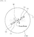
- FIG. 2 is a plan view schematically illustrating a state where an anemometer for a wind turbine according to the embodiment of the present disclosure is configured to be equipped in a nosecone and
- FIG. 3 is an enlarged view illustrating the anemometer for a wind turbine of FIG. 2 .
- an anemometer 110 for a wind turbine is used for a wind turbine including a plurality of rotating blades 10 and a hub 20 which is equipped at a rotation center of the plurality of rotating blades 10 and has a nosecone 21 and is equipped in the nosecone 21.
- the anemometer 110 for a wind turbine according to the embodiment of the present disclosure may be equipped at a center of a front end of the nosecone 21.
- the anemometer 110 for a wind turbine of the present disclosure is not affected by a wake generated by the rotation of the rotating blades 10 so that it is possible to precisely measure a wind velocity and a wind direction.
- the anemometer for a wind turbine may include a first ultrasonic sensor 114, a second ultrasonic sensor 115, a third ultrasonic sensor 116, and a fourth ultrasonic sensor 117.
- the first ultrasonic sensor 114 oscillates a first ultrasonic wave and receives a second ultrasonic wave from the second ultrasonic sensor 115 and the second ultrasonic sensor 115 oscillates the second ultrasonic wave and receives the first ultrasonic wave from the first ultrasonic sensor 114.
- the third ultrasonic sensor 116 oscillates a third ultrasonic wave in a first direction intersecting the first ultrasonic wave and receives a fourth ultrasonic wave transmitting in a second direction which is opposite to the first direction, from the fourth sensor 117.
- the fourth ultrasonic sensor 117 oscillates the fourth ultrasonic wave in the second direction and receives the third ultrasonic wave transmitting in the first direction, from the third ultrasonic sensor 116. Therefore, the first and second ultrasonic sensors 114 and 115 may measure a first wind velocity U 1 in the same direction as a transmitting direction of the first ultrasonic wave and the third and fourth ultrasonic sensors 116 and 117 may measure a second wind velocity U 2 in the same direction as a transmitting direction of the third ultrasonic wave.
- the anemometer 110 for a wind turbine of the present disclosure may sense the first and second wind velocities U 1 and U 2 in directions intersecting each other as illustrated in FIG. 3 .
- a first wind velocity U 1 is measured using a difference of a time when the second ultrasonic wave arrives the first ultrasonic sensor 114 and a time when the first ultrasonic wave arrives at the second ultrasonic sensor 115 and a second wind velocity U 2 is measured using a difference of a time when the fourth ultrasonic wave arrives at the third ultrasonic sensor 116 and a time when the third ultrasonic wave arrives at the fourth ultrasonic sensor 117.
- This is the same as the measurement principle of an existing ultrasonic anemometer, so that a specific description will be omitted.
- the anemometer 110 for a wind turbine may further include a support unit A which supports the first, second, third, and fourth ultrasonic sensors 114, 115, 116, and 117 to the nosecone 21.
- the first, second, third, and fourth ultrasonic sensors 114, 115, 116, and 117, the support unit A, and the rotary shaft S of the hub 20 may be disposed on one plane. In addition to this, as illustrated in FIG.
- the first, second, third, and fourth ultrasonic sensors 114, 115, 116, and 117, the support unit (not illustrated) , and the rotary shaft (see SD) of the hub 20 may be disposed on the same line L so as to dispose the transmitting direction of the first ultrasonic wave and the transmitting direction of the second ultrasonic wave on the same line L, as seen from the direction of the rotary shaft S.
- first, second, third, and fourth ultrasonic sensors 114, 115, 116, and 117 are disposed by the support unit A so as to intersect the first and third ultrasonic waves on an extending line (see SD) of the rotary shaft S, it is possible to precisely measure the first and second wind velocities U 1 and U 2 .
- the support unit A may include a center support shaft 111, a first support member 112, and a second support member 113.
- the center support shaft 111 is equipped in the nosecone 21 to coincide with the axial direction SD of the rotary shaft S.
- the first support member 112 is branched at a distal end of the center support shaft 111 and supports the first ultrasonic sensor 114 and the fourth ultrasonic sensor 117 and the second support member 113 is branched at a distal end of the center support shaft 111 and supports the second ultrasonic sensor 115 and the third ultrasonic sensor 116.
- the first and second support members 112 and 113 may be symmetrical with respect to the center support shaft 111 so as to be disposed on one plane.
- the first support member 112 may include a first branching unit 112a branched from the center support shaft 111 and a first mounting unit 112b which is provided at a distal end of the first branching unit 112a and supports the first ultrasonic sensor 114 and the fourth ultrasonic sensor 117 at both ends.
- the second support member 113 may include a second branching unit 113a branched from the center support shaft 111 and a second mounting unit 113b which is provided at a distal end of the second branching unit 113a and supports the second ultrasonic sensor 115 and the third ultrasonic sensor 116 at both ends.
- each of the first and second mounting units 112b and 113b may be equipped with an anti-freezing hot wire 119 for de-icing in the winter.
- an anti-freezing hot wire 119 for de-icing in the winter.
- two anti-freezing hot wires 119 are equipped in the first mounting unit 112b to be adjacent to the first and fourth ultrasonic sensors 114 and 117.
- another two anti-freezing hot wires 119 are equipped in the second mounting unit 113b to be adjacent to the second and third ultrasonic sensors 115 and 116.
- FIGS. 2 to 7 a yaw angle control apparatus of a wind turbine according to another embodiment of the present disclosure will be described with reference to FIGS. 2 to 7 .
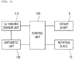
- FIG. 4 is a block diagram schematically illustrating a yaw angle control apparatus of a wind turbine according to another embodiment of the present disclosure
- FIG. 5 is a view illustrating a vector composition between velocities of an axial wind and a cross wind and first and second wind velocities measured by an anemometer
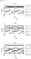
- FIG. 6 is a front view schematically illustrating a state where the nosecone of FIG. 2 rotates by a rotation angle ⁇
- FIG. 7 is a graph illustrating first and second wind velocities which vary by a rotation angle of a nosecone and velocities of axial wind and cross wind which are constantly maintained.
- a yaw angle control apparatus of a wind turbine is a yaw angle control apparatus for a wind turbine including a plurality of rotating blades 10 and a hub 20 which is equipped at a rotation center of the plurality of rotating blades 10 and has a nosecone 21.
- the above-described yaw angle control apparatus of a wind turbine includes the anemometer 110 according to the embodiment of the present disclosure, an arithmetic unit 120, and a control unit 130.
- components will be described in detail with reference to FIGS. 2 to 7 continuously.
- anemometer 110 is a component which measures first and second wind velocities U 1 and U 2 in intersecting directions and mentioned in the above-described embodiment of the present disclosure, so that a specific description will be omitted.
- the arithmetic unit 120 is a component which calculates a velocity U of the axial wind blowing in an axial direction SD of the rotary shaft S of the hub 20 and a velocity V of the cross wind blowing in a direction which is perpendicular to the rotary shaft S and is horizontal with the ground using first and second wind velocities U 1 and U 2 measured by the anemometer 110.
- the arithmetic unit 120 may calculate the velocity U of the axial wind and the velocity V of the cross wind by the following Equations 1 and 2. That is, the first and second wind velocities U 1 and U 2 measured by the anemometer 110 may be converted using a velocity U of the axial wind, a velocity V of a cross wind, and a velocity W of a vertical wind as represented in the following Equations.
- U 1 is a first wind velocity measured by the anemometer 110
- U 2 is a second wind velocity measured by the anemometer 110
- ⁇ is half an angle between U 1 and U 2
- ⁇ is a rotation angle of the nosecone 21.
- U is a velocity of the axial wind
- V is a velocity of a cross wind
- W is a velocity of a vertical wind blowing in a direction perpendicular to the ground.
- V ⁇ U 1 ⁇ ⁇ U 2 ⁇ / 2 ⁇ cos ⁇ ⁇ sin ⁇
- the velocity U of the axial wind is always calculated as a precise value (for example, 1.0).
- the velocity V of the cross wind is calculated as a precise value (for example, 0.2) only when " ⁇ " is "0" degree and "180" degrees.
- the ultrasonic wave may oscillate with a constant interval so that when " ⁇ " is “0" degree and "180" degrees, the wind velocity may not be necessarily measured.
- " ⁇ " is interpolated with a value of approximately “0" degree and "180” degrees so that a velocity V of a cross wind when " ⁇ " is 0 degree and 180 degrees may be obtained.
- velocities V of a cross wind when " ⁇ " is 0 degree and 180 degrees may not exactly match, an average of two values may be used as the velocity V of the cross wind.
- the control unit 130 is a component of controlling a yaw angle of the rotary shaft S and a pitch angle of the rotating blade 10 using the velocity U of the axial wind and the velocity V of the cross wind calculated by the arithmetic unit 120.
- control unit 130 determines whether an absolute value of the velocity V of the cross wind is smaller than an allowable reference value. Thereafter, when the absolute value of the velocity V of the cross wind is equal to or larger than the reference value, a yaw angle of the rotary shaft S may be adjusted. For reference, as the allowable reference value becomes smaller, the rotating blade 10 may be aligned to be opposite to the wind blowing direction as much as possible.
- the yaw angle of the rotary shaft S may be controlled such that the magnitude of the velocity V of the cross wind is reduced. Therefore, the rotating blade 10 is aligned to be opposite to the wind blowing direction as much as possible by controlling the yaw angle of the rotary shaft S so that the electricity generation efficiency of the wind turbine may be improved.
- the control unit 130 starts adjusting a pitch angle of the rotating blade 10 (that is, an installation angle of the rotating blade) so as to interwork with the velocity U of the cross wind. More, the details for controlling the pitch angle of the rotating blade 10 are not the subject of the present disclosure, so that the description will be omitted.
- control unit 130 may be implemented as one or more microprocessors which operate by a set program and the set program may include a series of commands for executing individual steps included in a method according to another embodiment of the present disclosure which will be described below.
- a yaw angle control method of a wind turbine according to another embodiment of the present disclosure will be described below.
- the first and second wind velocities U 1 and U 2 are measured using the anemometer 110 in step S110.
- the first and second wind velocities U 1 and U 2 are calculated as a velocity U of an axial wind and a velocity V of a cross wind using the arithmetic unit 120 in step S120.
- a yaw angle of the rotary shaft S is controlled using the calculated velocity V of a cross wind in step S130.
- the velocity U of an axial wind and the velocity V of a cross wind are calculated by Equations 1 and 2 mentioned in the above-described yaw angle control apparatus of a wind turbine according to the present disclosure so that a specific description will be omitted.
- step S130 it is determined whether an absolute value of the velocity V of a cross wind is smaller than an allowable reference value ⁇ in step S131. Thereafter, when the absolute value of the velocity V of a cross wind is equal to or larger than the allowable reference value ⁇ , a yaw angle of the rotary shaft S is adjusted in step S133. For reference, as the allowable reference value ⁇ becomes smaller, the rotating blade 10 may be aligned to be opposite to the wind blowing direction as much as possible.
- the yaw angle of the rotary shaft S may be controlled such that the magnitude of the velocity V of the cross wind is reduced. Therefore, the rotating blade 10 is aligned to be opposite to the wind blowing direction as much as possible by controlling the yaw angle of the rotary shaft S so that the electricity generation efficiency of the wind turbine may be improved.
- the control unit 130 starts adjusting a pitch angle of the rotating blade 10 (that is, an installation angle of the rotating blade) so as to interwork with the velocity U of the axial wind in step S132.
- the anemometer for a wind turbine according to embodiments of the present disclosure and an apparatus and a method for controlling a yaw angle of a wind turbine using the same have the following effects:
- an anemometer 110 for a wind turbine provides a technical configuration configured to be equipped in a nosecone 21 of a hub 20 of a wind turbine so that the anemometer 110 for a wind turbine is not affected by the wake generated by the rotation of the rotating blade 10, thereby precisely measuring a wind velocity and a wind direction.
- a technical component which includes an anemometer 110 for a wind turbine according to an exemplary embodiment of the present disclosure, an arithmetic unit 120, and a control unit 130 is provided.
- the anemometer 110 for a wind turbine configured to be equipped in the nosecone 21 measures first and second wind velocities U 1 and U 2 in intersecting directions, the arithmetic unit 120 calculates a velocity U of an axial wind and the velocity V of a cross wind using the first and second wind velocities U 1 and U 2, and a yaw angle of the rotary shaft S and the pitch angle of the rotating blade 10 are controlled using the velocities U and V of the axial wind and the cross wind.
Landscapes
- Engineering & Computer Science (AREA)
- Physics & Mathematics (AREA)
- Mechanical Engineering (AREA)
- Sustainable Energy (AREA)
- Chemical & Material Sciences (AREA)
- Combustion & Propulsion (AREA)
- Life Sciences & Earth Sciences (AREA)
- General Engineering & Computer Science (AREA)
- Sustainable Development (AREA)
- General Physics & Mathematics (AREA)
- Aviation & Aerospace Engineering (AREA)
- Acoustics & Sound (AREA)
- Multimedia (AREA)
- Fluid Mechanics (AREA)
- Wind Motors (AREA)
Claims (18)
- Anémomètre (110) pour une turbine éolienne incluant une pluralité de pales rotatives (10) et un moyeu (20) qui est monté au niveau d'un centre de rotation de la pluralité de pales rotatives et qui a un cône frontal (21),dans lequel l'anémomètre (110) est configuré pour être monté dans le cône frontal (21),caractérisé en ce quel'anémomètre comprend :un premier capteur à ultrasons (114) configuré pour faire osciller une première onde ultrasonore et pour recevoir une deuxième onde ultrasonore ;un deuxième capteur à ultrasons (115) configuré pour faire osciller la deuxième onde ultrasonore et pour recevoir la première onde ultrasonore ;un troisième capteur à ultrasons (116) configuré pour faire osciller une troisième onde ultrasonore dans une première direction recoupant la première onde ultrasonore et pour recevoir une quatrième onde ultrasonore dans une seconde direction opposée à la première direction ; etun quatrième capteur à ultrasons (117) configuré pour faire osciller la quatrième onde ultrasonore dans la seconde direction et pour recevoir la troisième onde ultrasonore dans la première direction,dans lequel le premier et le deuxième capteur à ultrasons (114, 115) sont configurés pour mesurer une première vitesse du vent (U1) dans la même direction que la direction de transmission de la première onde ultrasonore et le troisième et le quatrième capteur à ultrasons (116, 117) sont configurés pour mesurer une seconde vitesse du vent (U2) dans la même direction que la direction de transmission de la troisième onde ultrasonore.
- Anémomètre selon la revendication 1, comprenant en outre :
une unité de support (A) qui est configurée pour supporter le premier, le deuxième, le troisième et le quatrième capteur à ultrasons sur le cône frontal, dans lequel le premier, le deuxième, le troisième et le quatrième capteur à ultrasons et l'unité de support peuvent être disposés sur un même plan avec l'arbre rotatif (S) du moyeu (20). - Anémomètre selon la revendication 2, dans lequel l'unité de support (A) inclut :un arbre de support central (111) qui est configuré pour être monté dans le cône frontal de manière à coïncider avec une direction axiale (SD) de l'arbre rotatif ;un premier élément de support (112) qui se ramifie au niveau d'une extrémité distale de l'arbre de support central et qui supporte le premier capteur à ultrasons et le quatrième capteur à ultrasons ; etun second élément de support (113) qui se ramifie au niveau d'une extrémité distale de l'arbre de support central et qui supporte le deuxième capteur à ultrasons (115) et le troisième capteur à ultrasons (116).
- Anémomètre selon la revendication 3, dans lequel le premier élément de support (112) inclut :une première unité de ramification (112a) se ramifiant au niveau de l'arbre de support central ; etune première unité de montage (112b) qui est montée au niveau d'une extrémité distale de la première unité de ramification et qui supporte le premier capteur à ultrasons (114) et le quatrième capteur à ultrasons (117) au niveau des deux extrémités, etle second élément de support (113) inclut :une seconde unité de ramification (113a) se ramifiant au niveau de l'arbre de support central ; etune seconde unité de montage (113b) qui est montée niveau d'une extrémité distale de la seconde unité de ramification (113a) et qui supporte le deuxième capteur à ultrasons (115) et le troisième capteur à ultrasons (116) au niveau des deux extrémités.
- Anémomètre selon la revendication 4, dans lequel un fil chaud antigel (119) est monté dans chacune de la première et de la seconde unité de montage.
- Anémomètre selon la revendication 3, dans lequel la direction de transmission de la première onde ultrasonore et la direction de transmission de la troisième onde ultrasonore peuvent être disposées sur la même ligne, telle que vue depuis la direction de l'arbre rotatif (S).
- Appareil de commande d'angle de lacet d'une turbine éolienne comprenant l'anémomètre (110) selon l'une quelconque des revendications 1 à 6, et comprenant :une unité arithmétique (120) qui est configurée pour calculer une vitesse (U) du vent axial soufflant dans une direction axiale (SD) de l'arbre rotatif du moyeu et une vitesse (V) du vent transversal soufflant dans une direction qui est perpendiculaire à l'arbre rotatif et qui est horizontale par rapport au sol en utilisant la première et la seconde vitesse du vent mesurées par l'anémomètre ; etune unité de commande (130) qui est configurée pour commander l'angle de lacet de l'arbre rotatif en utilisant la vitesse du vent transversal calculée par l'unité arithmétique (120).
- Appareil de commande d'angle de lacet selon la revendication 7, dans lequel l'unité arithmétique (120) est configurée pour calculer la vitesse du vent axial et la vitesse du vent transversal en utilisant les équations 1 et 2 suivantes :


- Appareil de commande d'angle de lacet selon la revendication 8, dans lequel l'unité arithmétique (120) est configurée de telle sorte que, pour la vitesse V du vent transversal, une valeur moyenne quand φ est « 0 » degré et « 180 » degrés est utilisée.
- Appareil de commande d'angle de lacet selon la revendication 9, dans lequel l'unité de commande (130) est configurée pour effectuer des opérations incluant :de déterminer si une valeur absolue de la vitesse du vent transversal est plus petite qu'une valeur de référence permissible ; etd'ajuster l'angle de lacet quand la valeur absolue de la vitesse du vent transversal est égale ou supérieure à la valeur de référence.
- Appareil de commande d'angle de lacet selon la revendication 10, dans lequel l'unité de commande (130) est configurée de telle sorte que, dans l'opération d'ajustement de l'angle de lacet, l'angle de lacet de l'arbre rotatif est commandé de telle sorte qu'une ampleur de la vitesse du vent transversal est réduite.
- Appareil de commande d'angle de lacet selon la revendication 11, dans lequel l'unité de commande (130) est configurée pour effectuer des opérations incluant en outre :
de démarrer un ajustement d'un angle de pas de la pale de manière à interagir avec le vent axial quand la valeur absolue de la vitesse du vent transversal est plus petite que la valeur de référence. - Procédé de commande d'angle de lacet d'une turbine éolienne utilisant l'appareil de commande d'angle de lacet d'une turbine éolienne selon la revendication 7, le procédé comprenant les étapes consistant à :mesurer la première et la seconde vitesse du vent (U1, U2) ;calculer la vitesse (U) du vent axial et la vitesse (V) du vent transversal en utilisant la première et la seconde vitesse du vent mesurées ; etcommander un angle de lacet de l'arbre rotatif en utilisant la vitesse calculée du vent transversal.
- Procédé de commande d'angle de lacet selon la revendication 13, dans lequel, dans l'étape de calcul, la vitesse du vent axial et la vitesse du vent transversal sont calculées en utilisant les équations 1 et 2 suivantes,


- Procédé de commande d'angle de lacet selon la revendication 14, dans lequel, à titre de vitesse
V du vent transversal, une valeur moyenne quand φ est « 0 » degré et « 180 » degrés est utilisée. - Procédé de commande d'angle de lacet selon la revendication 13, dans lequel l'étape de commande inclut :de déterminer si une valeur absolue de la vitesse du vent transversal est plus petite qu'une valeur de référence permissible ; etd'ajuster l'angle de lacet quand la valeur absolue de la vitesse du vent transversal est égale ou supérieure à la valeur de référence.
- Procédé de commande d'angle de lacet selon la revendication 16, dans lequel, dans l'étape d'ajustement de l'angle de lacet, l'angle de lacet de l'arbre rotatif est commandé de telle sorte qu'une ampleur de la vitesse du vent transversal est réduite.
- Procédé de commande d'angle de lacet selon la revendication 16, dans lequel l'étape de commande inclut en outre :
de démarrer un ajustement d'un angle de pas de la pale de manière à interagir avec le vent axial quand la valeur absolue de la vitesse du vent transversal est plus petite que la valeur de référence.
Applications Claiming Priority (2)
| Application Number | Priority Date | Filing Date | Title |
|---|---|---|---|
| KR1020160117609A KR101715138B1 (ko) | 2016-09-12 | 2016-09-12 | 풍력 터빈용 풍향풍속 측정 장치와 이를 이용한 풍력 터빈의 요각 제어 장치 및 제어 방법 |
| PCT/KR2017/005746 WO2018048064A1 (fr) | 2016-09-12 | 2017-06-01 | Appareil de mesure de la direction du vent et de la vitesse du vent pour une éolienne ainsi que dispositif et procédé permettant de commander l'angle de lacet d'une éolienne à l'aide de ce dernier |
Publications (3)
| Publication Number | Publication Date |
|---|---|
| EP3467517A1 EP3467517A1 (fr) | 2019-04-10 |
| EP3467517A4 EP3467517A4 (fr) | 2020-02-19 |
| EP3467517B1 true EP3467517B1 (fr) | 2022-06-29 |
Family
ID=58411077
Family Applications (1)
| Application Number | Title | Priority Date | Filing Date |
|---|---|---|---|
| EP17848949.8A Active EP3467517B1 (fr) | 2016-09-12 | 2017-06-01 | Appareil de mesure de la direction du vent et de la vitesse du vent pour une éolienne ainsi que dispositif et procédé permettant de commander l'angle de lacet d'une éolienne à l'aide de ce dernier |
Country Status (4)
| Country | Link |
|---|---|
| US (1) | US10767635B2 (fr) |
| EP (1) | EP3467517B1 (fr) |
| KR (1) | KR101715138B1 (fr) |
| WO (1) | WO2018048064A1 (fr) |
Families Citing this family (9)
| Publication number | Priority date | Publication date | Assignee | Title |
|---|---|---|---|---|
| US11035340B2 (en) | 2014-08-05 | 2021-06-15 | Biomerenewables Inc. | Fluidic turbine structure |
| KR101822647B1 (ko) * | 2017-07-05 | 2018-01-26 | 한국항공우주연구원 | 회전하는 3차원 초음파 풍속계 및 이를 이용한 3차원 풍속 측정 방법 |
| CN108412690B (zh) * | 2018-01-19 | 2020-02-07 | 大唐东北电力试验研究所有限公司 | 一种三段式高风能捕获率的风力发电机组偏航方法及系统 |
| DE102018003608B3 (de) * | 2018-05-03 | 2019-05-29 | Promecon Process Measurement Control Gmbh | Windkraftmaschine |
| CN109268215A (zh) * | 2018-11-26 | 2019-01-25 | 中国华能集团清洁能源技术研究院有限公司 | 能够预测风力机尾迹及提高风电场发电量的装置及方法 |
| CN112145266B (zh) * | 2019-06-26 | 2022-01-11 | 陕西汽车集团股份有限公司 | 一种回收发动机排气脉冲能量的装置 |
| CN110346600B (zh) * | 2019-08-21 | 2021-04-06 | 南京信息工程大学 | 一种超声波风速风向测量方法 |
| CN112761903A (zh) * | 2021-02-26 | 2021-05-07 | 中国华能集团清洁能源技术研究院有限公司 | 一种风机轮毂中心恒流式热线风速感测系统及方法 |
| CN113495169B (zh) * | 2021-04-23 | 2022-03-15 | 中国大唐集团新能源科学技术研究院有限公司 | 风力机风轮前风速超声测量系统 |
Family Cites Families (9)
| Publication number | Priority date | Publication date | Assignee | Title |
|---|---|---|---|---|
| CA2560600C (fr) | 2004-03-26 | 2010-10-26 | Forskningscenter Risoe | Procede et appareil servant a determiner la vitesse et la direction du vent dans une eolienne |
| US8235662B2 (en) * | 2007-10-09 | 2012-08-07 | General Electric Company | Wind turbine metrology system |
| KR20100005051U (ko) | 2008-11-07 | 2010-05-17 | 한국에너지기술연구원 | 풍력발전기의 풍속 측정 장치 |
| EP2325480A1 (fr) * | 2009-11-24 | 2011-05-25 | Siemens Aktiengesellschaft | Procédé de contrôle d'une éolienne et système de contrôle de charge d'éolienne |
| KR101314811B1 (ko) | 2011-09-23 | 2013-10-04 | 삼성중공업 주식회사 | 풍력 발전기의 풍향 풍속 측정장치 |
| KR101313201B1 (ko) | 2011-12-13 | 2013-09-30 | 삼성중공업 주식회사 | 풍력발전기 |
| TW201402940A (zh) | 2012-02-08 | 2014-01-16 | Romo Wind Ag | 用於調整風力機之橫擺的裝置 |
| CN104956073B (zh) | 2012-12-26 | 2018-02-13 | 菱重维斯塔斯海上风力有限公司 | 控制装置及方法以及程序、具备该控制装置的浮体式风力发电装置 |
| KR101473664B1 (ko) | 2013-03-13 | 2014-12-17 | 두산중공업 주식회사 | 비회전 구조체를 이용한 풍력 발전기의 풍향풍속 측정장치 및 이를 이용한 나셀 제어시스템 |
-
2016
- 2016-09-12 KR KR1020160117609A patent/KR101715138B1/ko active Active
-
2017
- 2017-06-01 EP EP17848949.8A patent/EP3467517B1/fr active Active
- 2017-06-01 WO PCT/KR2017/005746 patent/WO2018048064A1/fr not_active Ceased
- 2017-06-01 US US16/315,731 patent/US10767635B2/en active Active
Also Published As
| Publication number | Publication date |
|---|---|
| KR101715138B1 (ko) | 2017-03-10 |
| EP3467517A4 (fr) | 2020-02-19 |
| US10767635B2 (en) | 2020-09-08 |
| US20190242366A1 (en) | 2019-08-08 |
| EP3467517A1 (fr) | 2019-04-10 |
| WO2018048064A1 (fr) | 2018-03-15 |
Similar Documents
| Publication | Publication Date | Title |
|---|---|---|
| EP3467517B1 (fr) | Appareil de mesure de la direction du vent et de la vitesse du vent pour une éolienne ainsi que dispositif et procédé permettant de commander l'angle de lacet d'une éolienne à l'aide de ce dernier | |
| EP2469083B1 (fr) | Éolienne en mer et son procédé de fonctionnement | |
| KR101476986B1 (ko) | 풍력 터빈용 제어 장치 | |
| EP2749766B1 (fr) | Procédé de détection d'un taux d'erreur de lacet d'une éolienne | |
| JP6001770B2 (ja) | 風力発電装置、および風力発電装置またはウィンドパークの制御方法 | |
| US8235662B2 (en) | Wind turbine metrology system | |
| US20100092292A1 (en) | Apparatus and method for continuous pitching of a wind turbine | |
| EP1907695B1 (fr) | Estimation du flux du vent et tracage au moyen de la dynamique d'une tour | |
| US20130272874A1 (en) | Method and device for determining a bending angle of a rotor blade of a wind turbine system | |
| CN107110125A (zh) | 用于确定风力涡轮机叶片的动态扭曲的方法和系统 | |
| EP3232051A1 (fr) | Procédé et dispositif de chargement pour la détection d'une pale de turbine éolienne | |
| BR112013018853B1 (pt) | método de operação de uma turbina eólica, sistema de controle de turbina eólica para o uso com uma turbina eólica e sistema de turbina eólica | |
| CN103906921B (zh) | 用于确定风力涡轮机的偏转角误差的方法和设备和风力涡轮机 | |
| US20230016798A1 (en) | Device for determining the distance between a wind turbine blade and its wind turbine tower at passing | |
| KR101314811B1 (ko) | 풍력 발전기의 풍향 풍속 측정장치 | |
| US20160377056A1 (en) | Method and system for improving energy capture efficiency from an energy capture device | |
| US20230258162A1 (en) | Measuring device for wind turbines | |
| CN102410139A (zh) | 确定转子共同叶片频率的方法和装置及操作风轮机的方法 | |
| JP2005061963A (ja) | 水平軸風車及び吹上角計測方法 | |
| KR20120048526A (ko) | 풍력발전 단지, 풍력발전 단지내에 위치한 풍력발전 플랜트 및 이를 위한 작동제어 | |
| US10871502B2 (en) | Rotating three-dimensional ultrasonic anemometer and method of measuring three-dimensional wind velocity using the same | |
| EP3918346A1 (fr) | Procédé et système de détermination de la vitesse ou de la direction du vent que subit une éolienne | |
| Pedersen et al. | Improvement of Wind Farm Performance by Means of Spinner Anemometry |
Legal Events
| Date | Code | Title | Description |
|---|---|---|---|
| STAA | Information on the status of an ep patent application or granted ep patent |
Free format text: STATUS: THE INTERNATIONAL PUBLICATION HAS BEEN MADE |
|
| PUAI | Public reference made under article 153(3) epc to a published international application that has entered the european phase |
Free format text: ORIGINAL CODE: 0009012 |
|
| STAA | Information on the status of an ep patent application or granted ep patent |
Free format text: STATUS: REQUEST FOR EXAMINATION WAS MADE |
|
| 17P | Request for examination filed |
Effective date: 20190103 |
|
| AK | Designated contracting states |
Kind code of ref document: A1 Designated state(s): AL AT BE BG CH CY CZ DE DK EE ES FI FR GB GR HR HU IE IS IT LI LT LU LV MC MK MT NL NO PL PT RO RS SE SI SK SM TR |
|
| AX | Request for extension of the european patent |
Extension state: BA ME |
|
| DAV | Request for validation of the european patent (deleted) | ||
| DAX | Request for extension of the european patent (deleted) | ||
| A4 | Supplementary search report drawn up and despatched |
Effective date: 20200116 |
|
| RIC1 | Information provided on ipc code assigned before grant |
Ipc: F03D 7/02 20060101ALI20200110BHEP Ipc: F03D 1/00 20060101ALI20200110BHEP Ipc: G01P 5/24 20060101AFI20200110BHEP Ipc: G01P 13/04 20060101ALI20200110BHEP |
|
| GRAP | Despatch of communication of intention to grant a patent |
Free format text: ORIGINAL CODE: EPIDOSNIGR1 |
|
| STAA | Information on the status of an ep patent application or granted ep patent |
Free format text: STATUS: GRANT OF PATENT IS INTENDED |
|
| INTG | Intention to grant announced |
Effective date: 20220111 |
|
| GRAS | Grant fee paid |
Free format text: ORIGINAL CODE: EPIDOSNIGR3 |
|
| GRAA | (expected) grant |
Free format text: ORIGINAL CODE: 0009210 |
|
| STAA | Information on the status of an ep patent application or granted ep patent |
Free format text: STATUS: THE PATENT HAS BEEN GRANTED |
|
| AK | Designated contracting states |
Kind code of ref document: B1 Designated state(s): AL AT BE BG CH CY CZ DE DK EE ES FI FR GB GR HR HU IE IS IT LI LT LU LV MC MK MT NL NO PL PT RO RS SE SI SK SM TR |
|
| REG | Reference to a national code |
Ref country code: CH Ref legal event code: EP |
|
| REG | Reference to a national code |
Ref country code: AT Ref legal event code: REF Ref document number: 1501675 Country of ref document: AT Kind code of ref document: T Effective date: 20220715 |
|
| REG | Reference to a national code |
Ref country code: IE Ref legal event code: FG4D |
|
| REG | Reference to a national code |
Ref country code: DE Ref legal event code: R096 Ref document number: 602017059085 Country of ref document: DE |
|
| REG | Reference to a national code |
Ref country code: LT Ref legal event code: MG9D |
|
| PG25 | Lapsed in a contracting state [announced via postgrant information from national office to epo] |
Ref country code: SE Free format text: LAPSE BECAUSE OF FAILURE TO SUBMIT A TRANSLATION OF THE DESCRIPTION OR TO PAY THE FEE WITHIN THE PRESCRIBED TIME-LIMIT Effective date: 20220629 Ref country code: NO Free format text: LAPSE BECAUSE OF FAILURE TO SUBMIT A TRANSLATION OF THE DESCRIPTION OR TO PAY THE FEE WITHIN THE PRESCRIBED TIME-LIMIT Effective date: 20220929 Ref country code: LT Free format text: LAPSE BECAUSE OF FAILURE TO SUBMIT A TRANSLATION OF THE DESCRIPTION OR TO PAY THE FEE WITHIN THE PRESCRIBED TIME-LIMIT Effective date: 20220629 Ref country code: HR Free format text: LAPSE BECAUSE OF FAILURE TO SUBMIT A TRANSLATION OF THE DESCRIPTION OR TO PAY THE FEE WITHIN THE PRESCRIBED TIME-LIMIT Effective date: 20220629 Ref country code: GR Free format text: LAPSE BECAUSE OF FAILURE TO SUBMIT A TRANSLATION OF THE DESCRIPTION OR TO PAY THE FEE WITHIN THE PRESCRIBED TIME-LIMIT Effective date: 20220930 Ref country code: FI Free format text: LAPSE BECAUSE OF FAILURE TO SUBMIT A TRANSLATION OF THE DESCRIPTION OR TO PAY THE FEE WITHIN THE PRESCRIBED TIME-LIMIT Effective date: 20220629 Ref country code: BG Free format text: LAPSE BECAUSE OF FAILURE TO SUBMIT A TRANSLATION OF THE DESCRIPTION OR TO PAY THE FEE WITHIN THE PRESCRIBED TIME-LIMIT Effective date: 20220929 |
|
| REG | Reference to a national code |
Ref country code: NL Ref legal event code: MP Effective date: 20220629 |
|
| REG | Reference to a national code |
Ref country code: AT Ref legal event code: MK05 Ref document number: 1501675 Country of ref document: AT Kind code of ref document: T Effective date: 20220629 |
|
| PG25 | Lapsed in a contracting state [announced via postgrant information from national office to epo] |
Ref country code: RS Free format text: LAPSE BECAUSE OF FAILURE TO SUBMIT A TRANSLATION OF THE DESCRIPTION OR TO PAY THE FEE WITHIN THE PRESCRIBED TIME-LIMIT Effective date: 20220629 Ref country code: LV Free format text: LAPSE BECAUSE OF FAILURE TO SUBMIT A TRANSLATION OF THE DESCRIPTION OR TO PAY THE FEE WITHIN THE PRESCRIBED TIME-LIMIT Effective date: 20220629 |
|
| PG25 | Lapsed in a contracting state [announced via postgrant information from national office to epo] |
Ref country code: NL Free format text: LAPSE BECAUSE OF FAILURE TO SUBMIT A TRANSLATION OF THE DESCRIPTION OR TO PAY THE FEE WITHIN THE PRESCRIBED TIME-LIMIT Effective date: 20220629 |
|
| PG25 | Lapsed in a contracting state [announced via postgrant information from national office to epo] |
Ref country code: SM Free format text: LAPSE BECAUSE OF FAILURE TO SUBMIT A TRANSLATION OF THE DESCRIPTION OR TO PAY THE FEE WITHIN THE PRESCRIBED TIME-LIMIT Effective date: 20220629 Ref country code: SK Free format text: LAPSE BECAUSE OF FAILURE TO SUBMIT A TRANSLATION OF THE DESCRIPTION OR TO PAY THE FEE WITHIN THE PRESCRIBED TIME-LIMIT Effective date: 20220629 Ref country code: RO Free format text: LAPSE BECAUSE OF FAILURE TO SUBMIT A TRANSLATION OF THE DESCRIPTION OR TO PAY THE FEE WITHIN THE PRESCRIBED TIME-LIMIT Effective date: 20220629 Ref country code: PT Free format text: LAPSE BECAUSE OF FAILURE TO SUBMIT A TRANSLATION OF THE DESCRIPTION OR TO PAY THE FEE WITHIN THE PRESCRIBED TIME-LIMIT Effective date: 20221031 Ref country code: ES Free format text: LAPSE BECAUSE OF FAILURE TO SUBMIT A TRANSLATION OF THE DESCRIPTION OR TO PAY THE FEE WITHIN THE PRESCRIBED TIME-LIMIT Effective date: 20220629 Ref country code: EE Free format text: LAPSE BECAUSE OF FAILURE TO SUBMIT A TRANSLATION OF THE DESCRIPTION OR TO PAY THE FEE WITHIN THE PRESCRIBED TIME-LIMIT Effective date: 20220629 Ref country code: AT Free format text: LAPSE BECAUSE OF FAILURE TO SUBMIT A TRANSLATION OF THE DESCRIPTION OR TO PAY THE FEE WITHIN THE PRESCRIBED TIME-LIMIT Effective date: 20220629 |
|
| PG25 | Lapsed in a contracting state [announced via postgrant information from national office to epo] |
Ref country code: PL Free format text: LAPSE BECAUSE OF FAILURE TO SUBMIT A TRANSLATION OF THE DESCRIPTION OR TO PAY THE FEE WITHIN THE PRESCRIBED TIME-LIMIT Effective date: 20220629 Ref country code: IS Free format text: LAPSE BECAUSE OF FAILURE TO SUBMIT A TRANSLATION OF THE DESCRIPTION OR TO PAY THE FEE WITHIN THE PRESCRIBED TIME-LIMIT Effective date: 20221029 |
|
| REG | Reference to a national code |
Ref country code: DE Ref legal event code: R097 Ref document number: 602017059085 Country of ref document: DE |
|
| PG25 | Lapsed in a contracting state [announced via postgrant information from national office to epo] |
Ref country code: AL Free format text: LAPSE BECAUSE OF FAILURE TO SUBMIT A TRANSLATION OF THE DESCRIPTION OR TO PAY THE FEE WITHIN THE PRESCRIBED TIME-LIMIT Effective date: 20220629 |
|
| PG25 | Lapsed in a contracting state [announced via postgrant information from national office to epo] |
Ref country code: DK Free format text: LAPSE BECAUSE OF FAILURE TO SUBMIT A TRANSLATION OF THE DESCRIPTION OR TO PAY THE FEE WITHIN THE PRESCRIBED TIME-LIMIT Effective date: 20220629 Ref country code: CZ Free format text: LAPSE BECAUSE OF FAILURE TO SUBMIT A TRANSLATION OF THE DESCRIPTION OR TO PAY THE FEE WITHIN THE PRESCRIBED TIME-LIMIT Effective date: 20220629 |
|
| PLBE | No opposition filed within time limit |
Free format text: ORIGINAL CODE: 0009261 |
|
| STAA | Information on the status of an ep patent application or granted ep patent |
Free format text: STATUS: NO OPPOSITION FILED WITHIN TIME LIMIT |
|
| 26N | No opposition filed |
Effective date: 20230330 |
|
| PG25 | Lapsed in a contracting state [announced via postgrant information from national office to epo] |
Ref country code: SI Free format text: LAPSE BECAUSE OF FAILURE TO SUBMIT A TRANSLATION OF THE DESCRIPTION OR TO PAY THE FEE WITHIN THE PRESCRIBED TIME-LIMIT Effective date: 20220629 |
|
| REG | Reference to a national code |
Ref country code: DE Ref legal event code: R119 Ref document number: 602017059085 Country of ref document: DE |
|
| PG25 | Lapsed in a contracting state [announced via postgrant information from national office to epo] |
Ref country code: MC Free format text: LAPSE BECAUSE OF FAILURE TO SUBMIT A TRANSLATION OF THE DESCRIPTION OR TO PAY THE FEE WITHIN THE PRESCRIBED TIME-LIMIT Effective date: 20220629 |
|
| PG25 | Lapsed in a contracting state [announced via postgrant information from national office to epo] |
Ref country code: MC Free format text: LAPSE BECAUSE OF FAILURE TO SUBMIT A TRANSLATION OF THE DESCRIPTION OR TO PAY THE FEE WITHIN THE PRESCRIBED TIME-LIMIT Effective date: 20220629 Ref country code: IT Free format text: LAPSE BECAUSE OF FAILURE TO SUBMIT A TRANSLATION OF THE DESCRIPTION OR TO PAY THE FEE WITHIN THE PRESCRIBED TIME-LIMIT Effective date: 20220629 |
|
| REG | Reference to a national code |
Ref country code: CH Ref legal event code: PL |
|
| REG | Reference to a national code |
Ref country code: BE Ref legal event code: MM Effective date: 20230630 |
|
| PG25 | Lapsed in a contracting state [announced via postgrant information from national office to epo] |
Ref country code: LU Free format text: LAPSE BECAUSE OF NON-PAYMENT OF DUE FEES Effective date: 20230601 |
|
| REG | Reference to a national code |
Ref country code: IE Ref legal event code: MM4A |
|
| PG25 | Lapsed in a contracting state [announced via postgrant information from national office to epo] |
Ref country code: LU Free format text: LAPSE BECAUSE OF NON-PAYMENT OF DUE FEES Effective date: 20230601 |
|
| PG25 | Lapsed in a contracting state [announced via postgrant information from national office to epo] |
Ref country code: IE Free format text: LAPSE BECAUSE OF NON-PAYMENT OF DUE FEES Effective date: 20230601 |
|
| PG25 | Lapsed in a contracting state [announced via postgrant information from national office to epo] |
Ref country code: IE Free format text: LAPSE BECAUSE OF NON-PAYMENT OF DUE FEES Effective date: 20230601 Ref country code: DE Free format text: LAPSE BECAUSE OF NON-PAYMENT OF DUE FEES Effective date: 20240103 Ref country code: CH Free format text: LAPSE BECAUSE OF NON-PAYMENT OF DUE FEES Effective date: 20230630 |
|
| PG25 | Lapsed in a contracting state [announced via postgrant information from national office to epo] |
Ref country code: FR Free format text: LAPSE BECAUSE OF NON-PAYMENT OF DUE FEES Effective date: 20230630 Ref country code: BE Free format text: LAPSE BECAUSE OF NON-PAYMENT OF DUE FEES Effective date: 20230630 |
|
| PG25 | Lapsed in a contracting state [announced via postgrant information from national office to epo] |
Ref country code: BG Free format text: LAPSE BECAUSE OF FAILURE TO SUBMIT A TRANSLATION OF THE DESCRIPTION OR TO PAY THE FEE WITHIN THE PRESCRIBED TIME-LIMIT Effective date: 20220629 |
|
| PG25 | Lapsed in a contracting state [announced via postgrant information from national office to epo] |
Ref country code: BG Free format text: LAPSE BECAUSE OF FAILURE TO SUBMIT A TRANSLATION OF THE DESCRIPTION OR TO PAY THE FEE WITHIN THE PRESCRIBED TIME-LIMIT Effective date: 20220629 |
|
| PGFP | Annual fee paid to national office [announced via postgrant information from national office to epo] |
Ref country code: GB Payment date: 20250407 Year of fee payment: 9 |
|
| PG25 | Lapsed in a contracting state [announced via postgrant information from national office to epo] |
Ref country code: CY Free format text: LAPSE BECAUSE OF FAILURE TO SUBMIT A TRANSLATION OF THE DESCRIPTION OR TO PAY THE FEE WITHIN THE PRESCRIBED TIME-LIMIT; INVALID AB INITIO Effective date: 20170601 |
|
| PG25 | Lapsed in a contracting state [announced via postgrant information from national office to epo] |
Ref country code: HU Free format text: LAPSE BECAUSE OF FAILURE TO SUBMIT A TRANSLATION OF THE DESCRIPTION OR TO PAY THE FEE WITHIN THE PRESCRIBED TIME-LIMIT; INVALID AB INITIO Effective date: 20170601 |
|
| PG25 | Lapsed in a contracting state [announced via postgrant information from national office to epo] |
Ref country code: TR Free format text: LAPSE BECAUSE OF FAILURE TO SUBMIT A TRANSLATION OF THE DESCRIPTION OR TO PAY THE FEE WITHIN THE PRESCRIBED TIME-LIMIT Effective date: 20220629 |