EP3467541B1 - Module de capteur - Google Patents
Module de capteur Download PDFInfo
- Publication number
- EP3467541B1 EP3467541B1 EP17195025.6A EP17195025A EP3467541B1 EP 3467541 B1 EP3467541 B1 EP 3467541B1 EP 17195025 A EP17195025 A EP 17195025A EP 3467541 B1 EP3467541 B1 EP 3467541B1
- Authority
- EP
- European Patent Office
- Prior art keywords
- measuring module
- angle measuring
- angle
- rangefinder
- sensor
- Prior art date
- Legal status (The legal status is an assumption and is not a legal conclusion. Google has not performed a legal analysis and makes no representation as to the accuracy of the status listed.)
- Active
Links
Images



Classifications
-
- G—PHYSICS
- G01—MEASURING; TESTING
- G01S—RADIO DIRECTION-FINDING; RADIO NAVIGATION; DETERMINING DISTANCE OR VELOCITY BY USE OF RADIO WAVES; LOCATING OR PRESENCE-DETECTING BY USE OF THE REFLECTION OR RERADIATION OF RADIO WAVES; ANALOGOUS ARRANGEMENTS USING OTHER WAVES
- G01S17/00—Systems using the reflection or reradiation of electromagnetic waves other than radio waves, e.g. lidar systems
- G01S17/02—Systems using the reflection of electromagnetic waves other than radio waves
- G01S17/06—Systems determining position data of a target
- G01S17/46—Indirect determination of position data
- G01S17/48—Active triangulation systems, i.e. using the transmission and reflection of electromagnetic waves other than radio waves
-
- G—PHYSICS
- G01—MEASURING; TESTING
- G01C—MEASURING DISTANCES, LEVELS OR BEARINGS; SURVEYING; NAVIGATION; GYROSCOPIC INSTRUMENTS; PHOTOGRAMMETRY OR VIDEOGRAMMETRY
- G01C3/00—Measuring distances in line of sight; Optical rangefinders
- G01C3/02—Details
- G01C3/06—Use of electric means to obtain final indication
- G01C3/08—Use of electric radiation detectors
-
- G—PHYSICS
- G01—MEASURING; TESTING
- G01S—RADIO DIRECTION-FINDING; RADIO NAVIGATION; DETERMINING DISTANCE OR VELOCITY BY USE OF RADIO WAVES; LOCATING OR PRESENCE-DETECTING BY USE OF THE REFLECTION OR RERADIATION OF RADIO WAVES; ANALOGOUS ARRANGEMENTS USING OTHER WAVES
- G01S17/00—Systems using the reflection or reradiation of electromagnetic waves other than radio waves, e.g. lidar systems
- G01S17/02—Systems using the reflection of electromagnetic waves other than radio waves
- G01S17/06—Systems determining position data of a target
- G01S17/08—Systems determining position data of a target for measuring distance only
-
- G—PHYSICS
- G01—MEASURING; TESTING
- G01S—RADIO DIRECTION-FINDING; RADIO NAVIGATION; DETERMINING DISTANCE OR VELOCITY BY USE OF RADIO WAVES; LOCATING OR PRESENCE-DETECTING BY USE OF THE REFLECTION OR RERADIATION OF RADIO WAVES; ANALOGOUS ARRANGEMENTS USING OTHER WAVES
- G01S17/00—Systems using the reflection or reradiation of electromagnetic waves other than radio waves, e.g. lidar systems
- G01S17/86—Combinations of lidar systems with systems other than lidar, radar or sonar, e.g. with direction finders
-
- G—PHYSICS
- G01—MEASURING; TESTING
- G01S—RADIO DIRECTION-FINDING; RADIO NAVIGATION; DETERMINING DISTANCE OR VELOCITY BY USE OF RADIO WAVES; LOCATING OR PRESENCE-DETECTING BY USE OF THE REFLECTION OR RERADIATION OF RADIO WAVES; ANALOGOUS ARRANGEMENTS USING OTHER WAVES
- G01S7/00—Details of systems according to groups G01S13/00, G01S15/00, G01S17/00
- G01S7/48—Details of systems according to groups G01S13/00, G01S15/00, G01S17/00 of systems according to group G01S17/00
- G01S7/4808—Evaluating distance, position or velocity data
-
- G—PHYSICS
- G01—MEASURING; TESTING
- G01S—RADIO DIRECTION-FINDING; RADIO NAVIGATION; DETERMINING DISTANCE OR VELOCITY BY USE OF RADIO WAVES; LOCATING OR PRESENCE-DETECTING BY USE OF THE REFLECTION OR RERADIATION OF RADIO WAVES; ANALOGOUS ARRANGEMENTS USING OTHER WAVES
- G01S7/00—Details of systems according to groups G01S13/00, G01S15/00, G01S17/00
- G01S7/48—Details of systems according to groups G01S13/00, G01S15/00, G01S17/00 of systems according to group G01S17/00
- G01S7/51—Display arrangements
-
- G—PHYSICS
- G01—MEASURING; TESTING
- G01B—MEASURING LENGTH, THICKNESS OR SIMILAR LINEAR DIMENSIONS; MEASURING ANGLES; MEASURING AREAS; MEASURING IRREGULARITIES OF SURFACES OR CONTOURS
- G01B21/00—Measuring arrangements or details thereof, where the measuring technique is not covered by the other groups of this subclass, unspecified or not relevant
- G01B21/22—Measuring arrangements or details thereof, where the measuring technique is not covered by the other groups of this subclass, unspecified or not relevant for measuring angles or tapers; for testing the alignment of axes
-
- G—PHYSICS
- G01—MEASURING; TESTING
- G01C—MEASURING DISTANCES, LEVELS OR BEARINGS; SURVEYING; NAVIGATION; GYROSCOPIC INSTRUMENTS; PHOTOGRAMMETRY OR VIDEOGRAMMETRY
- G01C15/00—Surveying instruments or accessories not provided for in groups G01C1/00 - G01C13/00
- G01C15/002—Active optical surveying means
Definitions
- the present invention relates to a sensor unit ("angle measuring module") that can be modularly connected to a hand-held distance measuring device and a modular system composed of a hand-held distance measuring device and such a sensor unit.
- stationary, movable or handheld distance measuring devices which carry out an optical distance measurement to a selected measuring point.
- a laser beam is emitted and, after being reflected at the target, is received and evaluated again.
- Various measuring principles are available to determine the distance, such as: B. phase or transit time measurement.
- portable devices that can be held in the hand are used, which are applied with respect to a structure to be measured and then carry out a distance measurement to a surface.
- a typical handheld distance measuring device that is suitable and typical for such applications is shown, for example, in US Pat EP 0 738 899 and the EP 0 701 702 described.
- red lasers are mostly used as radiation sources for distance measurement used.
- distance meters of the prior art accuracies down to the millimeter range can be achieved with great ease of use.
- Handheld distance measuring devices available up to now have a specific sensor configuration and thus have a fixed range of functions ex works, with a larger range of functions usually making the device larger and heavier.
- the device becomes unwieldy as the range of functions increases, and its use becomes strenuous and complicated for the user.
- the user can alternatively purchase several more compact distance measuring devices with different functional ranges.
- this is unnecessarily expensive, and it is also cumbersome to carry all these distance measuring devices.
- Another object of the present invention is to provide an exchangeable sensor module for expanding the functional scope of a handheld distance measuring device.
- Another object of the invention is to provide such a sensor module with little structural effort.
- a first aspect of the invention relates to a sensor module according to claim 1.
- the sensor module does not have its own power supply.
- the sensor module is the sensor module as an angle measurement module for measuring at least one angle configured between the distance measuring device and a base, wherein the at least one electronic sensor component comprises at least one angle sensor.
- the sensor module is designed as an angle measurement module for measuring at least two angles between the distance measuring device and a base, the at least one electronic sensor component comprising at least two angle sensors.
- the at least one electronic sensor component comprises a laser range finder.
- the sensor module has an extendable tape measure
- the electronic sensor component is designed to detect an extension of the tape measure.
- the electronic sensor component comprises an absolute encoder.
- the electronic sensor component comprises a color sensor and / or a thermographic camera.
- the electronic sensor component comprises a humidity sensor and / or temperature sensor.
- a second aspect of the invention relates to a system for hand-held measurement of distances to a surface area of an object according to claim 8.
- the distance measuring device has a first electronic interface and the sensor module has a second electronic interface, the first and second interfaces being designed to be connected to one another and to provide a data connection between the distance measuring device and the sensor module.
- the sensor module is designed to provide the distance measuring device with the sensor data via the data connection, and the distance measuring device has a computing component for processing the sensor data.
- the first and second interfaces are designed to transmit electrical energy from the distance measuring device to the sensor module, and the sensor module is designed to operate the at least one sensor component with the transmitted energy.
- the distance measuring device has an accumulator battery to provide the electrical energy.
- the first laser rangefinder is designed to emit a first laser beam in a first emission direction to a first target point.
- the at least one electronic sensor component comprises a second laser range finder which is used to emit a second laser beam in a second emission direction onto a second target point is configured, in particular wherein the first and the second emission direction are parallel or orthogonal.
- the computing unit is designed to calculate a distance to a target point based on the sensor data.
- the distance measuring device has a display unit for outputting measured distances, in particular configured as a touchscreen, the display unit also being configured for outputting the sensor data.
- the sensor module is designed as an angle measuring module for measuring at least one angle between the distance measuring device and a base, wherein the at least one electronic sensor component comprises at least one angle sensor, and the computing unit is designed to, based on measured distances, to a first and a second target point and to calculate a distance between the first and the second target point based on sensor data generated between the measurements by the at least one angle sensor.
- the laser emitting unit 11a emits a laser beam 30 to a measuring point 6 on an object (for example a wall).
- the object has a naturally rough surface from which optical rays are scatteredly reflected.
- Some of the scattered reflected beams 31 of the laser beam 30 are collected by the laser receiving unit 11b, detected and converted into an electrical signal.
- the signal is evaluated in a manner known per se in order to determine the digital value of the distance 5 by an electronic circuit.
- z. B. phase or transit time measurement can be used.
- the extension between the laser receiving unit 11b and a measuring stop is also taken into account.
- the value of the measured distance 5 determined digitally by the evaluation is then made available to a user by the display device 17.
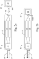
- Figure 2a shows a system comprising a distance measuring device 10 and a sensor module 20 that can be connected to it in a longitudinal sectional view.
- the distance measuring device 10 has a laser distance measuring device 11 for measuring distances to distant objects. This is designed to emit a laser beam 30 and to receive scattered reflected beams 31 of the laser beam.
- the distance measuring device also has a touchscreen 17 as an input and display device.
- a computing component 13 with an electronic circuit for processing data provided by the laser rangefinder 11 are provided as internal components Sensor data and an accumulator 15 for providing electrical energy for the components of the distance measuring device 10 are shown.
- the distance measuring device 10 has a first electronic interface 18 for connecting the distance measuring device 10 to an external sensor module 20 to form a system according to the invention.
- the sensor module 20 has an electronic sensor component 22 and a second electronic interface 28 that is compatible with the first electronic interface 18.
- the two interfaces 18, 28 are specifically designed to be connected to one another and to transmit both data and electrical power.
- the distance measuring device 10 and the sensor module 20 are off Figure 2a shown in the connected state.
- the interfaces 18 and 28 are plugged together in such a way that there is a data connection between the distance measuring device 10 and the sensor module 20, so that sensor data from the sensor component 22 can be transmitted to the computing unit 13.
- the connected interfaces enable the sensor module 20 to be supplied with power via the accumulator of the distance measuring device 10, so that the electronic sensor component 22 of the sensor module 20 can acquire the sensor data.
- the sensor module 20 to be of passive design, that is to say it does not need to have its own energy supply. As a result, it can advantageously be designed to be particularly compact and light.
- distance measuring device 10 and sensor module 20 have additional interfaces 18, 28 in addition to electronic interfaces Connecting elements for mechanical fixation to one another.
- the housings of distance measuring device 10 and sensor module 20 are preferably designed and coordinated with one another in such a way that their surfaces are flush when they are connected.
- sensor components 22 In principle, all electronic sensors that require electricity to function and generate the sensor data are conceivable as sensor components 22.
- these can be sensors that supplement generic functions of the distance measuring device directly or indirectly, or provide a user with additional measurement-relevant information, for example inclination sensors, additional laser distance measuring devices (see FIG Figure 4 ) or homing cameras.
- those sensors can also advantageously be used which are useful for a user who uses the distance measuring device 10 in the context of his activity. In the context of building installation or building acceptance, this can be, for example, a humidity and / or temperature sensor.
- the sensor component 22 can also be designed as a color sensor or thermographic camera. Due to the modular structure, which enables a quick change between different sensor modules 20, a wide variety of functions can advantageously be made available to the user.
- FIG 3 schematically illustrates the flow of data and energy in the system Figure 2b . Data flows are shown with solid lines, and current flows with dotted lines.
- the energy supply unit 15 (e.g. an accumulator battery) of the distance measuring device supplies the other components of the distance measuring device, i.e. the laser distance measuring device 11, the computing unit 13 and the display unit 17, on the one hand, and it also provides electrical energy for the first interface 18.
- the sensor component 22 of the sensor module is likewise supplied with power by the energy supply unit 15.
- the laser rangefinder 11 provides the computing unit 13 with data that can be used to determine a distance to an aimed target. This distance can then be provided to the display unit 17 in order to display it to a user.
- the sensor component 22 of the connected sensor module also provides data for the computing unit 13 via the two interfaces, which data can, for example, flow into the calculation of the distance or can be displayed to the user on the display unit 17.
- FIG. 4 shows a first exemplary embodiment of a system according to the invention.
- the distance measuring device 10 corresponds to that in FIG Figure 2b shown.
- the sensor module 20 has a second laser range finder 21 as a sensor component. This is designed to emit a second laser beam 30 'and to receive scattered reflected beams 31' of the second laser beam.
- the second laser range finder 21 is supplied with energy via the interfaces 18, 28 from the energy supply unit 15 of the range finder 10.
- the second laser rangefinder 21 also sends the data recorded by it to the via the interfaces 18, 28 Computing unit 13 of distance measuring device 10. For example, a total distance between two measuring points targeted by laser beams 30, 30 'can then be determined and displayed.
- Figure 5 shows a second exemplary embodiment of a system according to the invention.
- the sensor module has an extendable tape measure 50.
- the sensor component supplied with energy by the energy supply unit 15 of the distance measuring device 10 is designed here as an absolute value encoder 25, by means of which an extension of the tape measure 50 can be determined. This value can be transmitted to the computing unit 13.
- an absolute value encoder 25 by means of which an extension of the tape measure 50 can be determined.
- This value can be transmitted to the computing unit 13.
- a distance between a measuring point targeted by the laser beam 30 and an attachment point defined by the end of the tape measure 50 can then be determined and displayed to the user on the display unit 17.
- a third exemplary embodiment of a system according to the invention is shown, by means of which, inter alia, measurements can be carried out between two distant points.
- Many handheld rangefinders currently available also allow measurements to be taken from one point to another with a line of sight.
- One way of determining a distance between two points, which can also be used when there is no line of sight between the points, is calculation using trigonometry. This is already well known from ground-based surveying devices such as theodolites or total stations.
- a handheld rangefinder of the generic type with this capability is disclosed in WO 2014/027002 A1 described, but does not have the modular structure according to the invention.
- Figure 6a shows the sensor module configured as an angle measurement module 60. This has a receptacle 61 which, together with the interface 28, is designed for attachment of a distance measuring device 10 without play.
- the angle measuring module 60 is shown with the distance measuring device 10 attached to it.
- the Figure 6c shows an exemplary embodiment of the distance measuring device 10 fastened to an angle measuring module 60 in a three-dimensional view.
- the angle measuring module 60 is on a base 64, e.g. B. a tripod, designed to be fastened and provides adjustability of the alignment of the distance measuring device 10 in two degrees of freedom with respect to the base 64.
- the receptacle 61 is rotatably mounted with respect to a support 62 by means of a first hinge 66a, and the support 62 with respect to the base 64 by means of a second hinge 66b.
- Two angle sensors 26a and 26b on the hinges 66a, 66b are designed to determine a respective angle of rotation and to provide the corresponding data to the computing unit 13 of the connected distance measuring device 10.
- the angle measuring module 60 is designed to be passive, i. H. it does not have its own power supply, but rather draws the energy for the angle sensors 26a and 26b via the interfaces 18, 28 through the energy supply unit 15 of the distance measuring device 10.
- electric motors can be provided in order to change the alignment of the distance measuring device 10 in a motorized manner. These can also be provided by the power supply unit 15 of the distance measuring device 10 are supplied with the necessary electrical energy.
Landscapes
- Physics & Mathematics (AREA)
- Engineering & Computer Science (AREA)
- Radar, Positioning & Navigation (AREA)
- Remote Sensing (AREA)
- Electromagnetism (AREA)
- General Physics & Mathematics (AREA)
- Computer Networks & Wireless Communication (AREA)
- Optical Radar Systems And Details Thereof (AREA)
- Length Measuring Devices By Optical Means (AREA)
Claims (14)
- Module de mesure d'angle (60) prévu pour être relié de façon modulaire à un appareil de mesure de distance portatif (10) et pour fournir des données de détection à l'appareil de mesure de distance (10), présentant- une interface électronique (28) prévue pour être reliée à une interface correspondante (18) de l'appareil de mesure de distance (10) et- au moins un composant de détection électronique prévu pour générer les données de détection, ledit au moins un composant de détection électronique comprenant au moins un capteur d'angle (26a, 26b),le module de mesure d'angle (60)- étant conçu pour être fixé sur une base (64) et fournissant une possibilité de réglage de l'orientation de l'appareil de mesure de distance (10) selon deux degrés de liberté par rapport à la base (64),- étant conçu pour mesurer au moins un angle entre l'appareil de mesure de distance (10) et la base (64), et- étant conçu pour transmettre les données de détection à l'appareil de mesure de distance (10) lorsque l'interface électronique (28) est reliée à l'interface correspondante (18) de l'appareil de mesure de distance (10),caractérisé en ce que- l'interface électronique (28) est conçue pour transmettre de l'énergie électrique de l'appareil de mesure de distance (10) au module de mesure d'angle (60) lorsqu'elle est reliée à l'interface correspondante (18) de l'appareil de mesure de distance (10) et- le module de mesure d'angle (60) est conçu pour faire fonctionner ledit au moins un composant de détection (21, 22, 25, 26) au moyen de l'énergie électrique transmise par l'appareil de mesure de distance (10).
- Module de mesure d'angle (60) selon la revendication 1,
caractérisé en ce que
le module de mesure d'angle (60) ne dispose pas de sa propre alimentation électrique. - Module de mesure d'angle (60) selon la revendication 1 ou la revendication 2, caractérisé en ce que
le module de mesure d'angle (60) est conçu pour mesurer au moins deux angles entre l'appareil de mesure de distance (10) et la base (64), ledit au moins un composant de détection électronique comprenant au moins deux capteurs d'angle (26a, 26b). - Module de mesure d'angle (60) selon l'une des revendications précédentes, caractérisé en ce que
la base (64) est un trépied. - Module de mesure d'angle (60) selon l'une des revendications précédentes, caractérisé par
un logement (61) qui est conçu, conjointement avec l'interface (28), pour la fixation sans jeu de l'appareil de mesure de distance (10). - Module de mesure d'angle (60) selon la revendication 5,
caractérisé en ce que
le logement (61) est monté de manière rotative par rapport à un support (62) au moyen d'une première charnière (66a) et le support (62) est monté de manière rotative par rapport à la base (64) au moyen d'une deuxième charnière (66b), deux capteurs d'angle (26a, 26b) sur les charnières (66a, 66b) étant conçus pour déterminer un angle de rotation respectif et pour fournir les données correspondantes à une unité de calcul (13) d'un appareil de mesure de distance (10) relié. - Module de mesure d'angle (60) selon l'une des revendications précédentes, caractérisé par
des moteurs électriques qui sont conçus pour modifier de manière motorisée une orientation de l'appareil de mesure de distance (10). - Système pour la mesure à la main de distances (5) à une zone de surface d'un objet, le système étant de construction modulaire et présentant un appareil de mesure de distance portatif (10) comportant un appareil de mesure de distance par laser (11) et un module de mesure d'angle (60) comportant au moins un composant de détection électronique (21, 22, 25, 26) pour générer des données de détection, dans lequel :- le module de mesure d'angle (60) est conçu pour être fixé sur la base (64) et fournit une possibilité de réglage de l'orientation de l'appareil de mesure de distance (10) selon deux degrés de liberté par rapport à la base (64),- le module de mesure d'angle (60) est conçu pour mesurer au moins un angle entre l'appareil de mesure de distance (10) et la base (64),- ledit au moins un composant de détection électronique comprend au moins un capteur d'angle (26a, 26b),- l'appareil de mesure de distance (10) présente une première interface électronique (18),- le module de mesure d'angle (60) présente une deuxième interface électronique (28),- la première et la deuxième interface (18, 28) sont conçues pour être reliées entre elles et pour fournir une liaison de données entre l'appareil de mesure de distance (10) et le module de mesure d'angle (60),- le module de mesure d'angle (60) est conçu pour fournir les données de détection à l'appareil de mesure de distance (10) via la liaison de données et- l'appareil de mesure de distance (10) présente un composant de calcul (13) pour traiter les données de détection,caractérisé en ce que- la première et la deuxième interface (18, 28) sont conçues pour transmettre de l'énergie électrique de l'appareil de mesure de distance (10) au module de mesure d'angle (60),- le module de mesure d'angle (60) est conçu pour faire fonctionner ledit au moins un capteur d'angle (26a, 26b) avec l'énergie transmise et- l'unité de calcul (13) est conçue pour, sur la base des distances mesurées (5) à un premier et un deuxième point cible (6) et de données de détection générées entre les mesures par ledit au moins un capteur d'angle (26a, 26b), calculer une distance entre le premier et le deuxième point cible (6).
- Système selon la revendication 8,
caractérisé en ce que
l'appareil de mesure de distance (10) présente une batterie d'accumulateurs (15) pour fournir l'énergie électrique. - Système selon la revendication 8 ou la revendication 9,
caractérisé en ce que
le module de mesure d'angle (60) est conçu selon l'une des revendications 1 à 7. - Système selon l'une des revendications 8 à 10,
caractérisé en ce que
l'appareil de mesure de distance par laser (11) est conçu pour émettre un faisceau laser (30) dans une direction d'émission vers un point cible (6). - Système selon la revendication 11,
caractérisé en ce que
l'unité de calcul (13) est conçue pour calculer une distance (5) à un point cible (6) également sur la base des données de détection. - Système selon l'une des revendications 9 à 12,
caractérisé en ce que
l'appareil de mesure de distance (10) présente une unité d'affichage (17) pour fournir en sortie les distances mesurées, l'unité d'affichage (17) étant également conçue pour fournir en sortie les données de détection. - Système selon la revendication 13,
caractérisé en ce que
l'unité d'affichage (17) est conçue comme un écran tactile.
Priority Applications (3)
| Application Number | Priority Date | Filing Date | Title |
|---|---|---|---|
| EP17195025.6A EP3467541B1 (fr) | 2017-10-05 | 2017-10-05 | Module de capteur |
| CN201811146696.3A CN109633673B (zh) | 2017-10-05 | 2018-09-29 | 传感器模块 |
| US16/151,567 US11402203B2 (en) | 2017-10-05 | 2018-10-04 | Sensor module for applications with handheld rangefinder instrument |
Applications Claiming Priority (1)
| Application Number | Priority Date | Filing Date | Title |
|---|---|---|---|
| EP17195025.6A EP3467541B1 (fr) | 2017-10-05 | 2017-10-05 | Module de capteur |
Publications (2)
| Publication Number | Publication Date |
|---|---|
| EP3467541A1 EP3467541A1 (fr) | 2019-04-10 |
| EP3467541B1 true EP3467541B1 (fr) | 2022-01-05 |
Family
ID=60043029
Family Applications (1)
| Application Number | Title | Priority Date | Filing Date |
|---|---|---|---|
| EP17195025.6A Active EP3467541B1 (fr) | 2017-10-05 | 2017-10-05 | Module de capteur |
Country Status (3)
| Country | Link |
|---|---|
| US (1) | US11402203B2 (fr) |
| EP (1) | EP3467541B1 (fr) |
| CN (1) | CN109633673B (fr) |
Cited By (1)
| Publication number | Priority date | Publication date | Assignee | Title |
|---|---|---|---|---|
| US20240011772A1 (en) * | 2022-07-06 | 2024-01-11 | Robbox Inc. | Digital measuring and detection apparatus with interactive screen |
Families Citing this family (6)
| Publication number | Priority date | Publication date | Assignee | Title |
|---|---|---|---|---|
| DE102012107253B3 (de) | 2012-08-08 | 2013-05-29 | Karsten Bettin | Fahrrad |
| EP3425334B1 (fr) * | 2017-07-07 | 2022-09-07 | Leica Geosystems AG | Niveau laser |
| CN110609292A (zh) * | 2019-09-17 | 2019-12-24 | 上海器外文化科技有限公司 | 一种可测量不同平面上二点间距的手持激光测距仪及其测量方法 |
| KR102658734B1 (ko) | 2019-09-18 | 2024-04-19 | 삼성전자주식회사 | 디스플레이장치 및 그의 제어방법 |
| US12130154B2 (en) * | 2019-10-02 | 2024-10-29 | Top Measure Instrument Company | Automatic electronic rangefinder |
| EP3855112A1 (fr) * | 2020-01-22 | 2021-07-28 | Leica Geosystems AG | Instrument géodésique comprenant une base et un module de relevé géodésique et/ou de projection |
Citations (1)
| Publication number | Priority date | Publication date | Assignee | Title |
|---|---|---|---|---|
| FR2876445A1 (fr) * | 2004-02-19 | 2006-04-14 | Measurix Sarl | Dispositif et procede de mesure de la superficie de surfaces planes polygonales dans l'espace. |
Family Cites Families (33)
| Publication number | Priority date | Publication date | Assignee | Title |
|---|---|---|---|---|
| DE4316348A1 (de) | 1993-05-15 | 1994-11-17 | Wild Heerbrugg Ag | Vorrichtung zur Distanzmessung |
| US5859693A (en) * | 1997-08-26 | 1999-01-12 | Laser Technology, Inc. | Modularized laser-based survey system |
| JP3987437B2 (ja) | 2000-12-21 | 2007-10-10 | ライカ ジオシステムズ アクチェンゲゼルシャフト | 測長器と取り付け部材からなる測長装置 |
| DE10214742A1 (de) * | 2002-04-02 | 2003-10-16 | Hilti Ag | Optisches Lateraldistanzhandmessgerät |
| JP2004101229A (ja) * | 2002-09-05 | 2004-04-02 | Masahiro Koura | ゴルフ競技者位置計測装置及びゴルフ競技者位置計測システム |
| US6928029B2 (en) * | 2003-11-20 | 2005-08-09 | Brandon Rickman | Combination tape measure and range finder |
| GB0328508D0 (en) * | 2003-12-09 | 2004-01-14 | Wright Anthony T | Data processing device |
| EP1566658A1 (fr) | 2004-02-19 | 2005-08-24 | Leica Geosystems AG | Appareil à main de measure de la distance |
| EP1944572B1 (fr) * | 2005-09-12 | 2010-03-03 | Trimble Jena GmbH | Instrument d'arpentage et procédé pour fournir des données d'arpentage à l'aide de l'instrument d'arpentage |
| KR100631302B1 (ko) * | 2006-01-04 | 2006-10-04 | 주식회사코메론 | 휴대용 측정기 |
| DE102008042440A1 (de) | 2008-09-29 | 2010-04-01 | Robert Bosch Gmbh | Vorrichtung zur Längenmessung und Adapter zur Aufnahme einer Vorrichtung zur Längenmessung |
| US8314923B2 (en) * | 2009-07-23 | 2012-11-20 | Leupold & Stevens, Inc. | Configurable rangefinding devices and methods |
| DE102009040468A1 (de) * | 2009-09-08 | 2011-03-17 | Hesse, Christian, Dr.-Ing. | Tragbare mobile Erfassungseinrichtung und Verfahren zur dreidimensionalen geometrischen Erfassung einer Umgebung |
| CN101776758B (zh) * | 2010-02-09 | 2012-10-10 | 卢波 | 一种测定两个目标点之间距离的测距仪 |
| US8615376B2 (en) * | 2010-05-21 | 2013-12-24 | Sure-Shot Medical Device Inc. | Method and apparatus for dimensional measurement |
| GB2483721A (en) * | 2010-09-20 | 2012-03-21 | Witold Marian Gamski | Survey tool for assessing construction or maintenance jobs |
| EP2557392A1 (fr) * | 2011-08-11 | 2013-02-13 | Leica Geosystems AG | Dispositif de mesure et procédé doté d'une fonctionnalité de ciblage échelonnable et basée sur l'orientation d'une unité de télécommande |
| CN103364757B (zh) * | 2012-03-28 | 2017-07-21 | 富泰华工业(深圳)有限公司 | 便携式电子装置及其测距装置 |
| US20130271744A1 (en) * | 2012-04-13 | 2013-10-17 | Kama-Tech (Hk) Limited | Laser rangefinder module for operative association with smartphones and tablet computers |
| EP2698602A1 (fr) | 2012-08-16 | 2014-02-19 | Leica Geosystems AG | Appareil de mesure de distance pouvant être tenu à la main avec unité de détermination d'angle |
| EP2698600A1 (fr) * | 2012-08-16 | 2014-02-19 | Leica Geosystems AG | Module de télémétrie |
| TWM447982U (zh) * | 2012-09-28 | 2013-03-01 | Precaster Entpr Co Ltd | 雙系統量測裝置 |
| US10162056B2 (en) * | 2013-02-27 | 2018-12-25 | Ivan Arbouzov | Laser range finding attachment for mobile computing device |
| US20140378184A1 (en) * | 2013-06-25 | 2014-12-25 | Nvidia Corporation | Mobile communications device having a distance sensor and a method of manufacturing the same |
| US9714830B2 (en) * | 2013-07-26 | 2017-07-25 | Chervon (Hk) Limited | Measuring system and operating method thereof |
| US9846034B2 (en) * | 2014-01-23 | 2017-12-19 | Sure Hang, Llc | Adjustable laser leveling device with distance measuring lasers and self-leveling lasers and related method |
| JP2016049231A (ja) * | 2014-08-29 | 2016-04-11 | ソニー株式会社 | ゴルフスイング測定システム及びスイング測定器 |
| US20160341546A1 (en) * | 2015-05-18 | 2016-11-24 | Tae Hwi An | System and Method for Determination of Distance Between Two Points in 3-Dimensional Space |
| JP6577295B2 (ja) * | 2015-08-26 | 2019-09-18 | 株式会社トプコン | 測定装置 |
| CN205246877U (zh) * | 2015-12-25 | 2016-05-18 | 浙江久正工程检测有限公司 | 一种手持式激光测距仪 |
| AU2017250013A1 (en) * | 2016-04-14 | 2018-10-11 | MGI Golf Pty Ltd | Distance detector |
| CN106199556B (zh) * | 2016-06-24 | 2019-01-18 | 南京理工大学 | 一种自主驾驶用车载激光雷达的旋转扫描装置 |
| CN106403913A (zh) * | 2016-10-20 | 2017-02-15 | 桂林电子科技大学 | 一种测绘装置、系统及方法 |
-
2017
- 2017-10-05 EP EP17195025.6A patent/EP3467541B1/fr active Active
-
2018
- 2018-09-29 CN CN201811146696.3A patent/CN109633673B/zh active Active
- 2018-10-04 US US16/151,567 patent/US11402203B2/en active Active
Patent Citations (1)
| Publication number | Priority date | Publication date | Assignee | Title |
|---|---|---|---|---|
| FR2876445A1 (fr) * | 2004-02-19 | 2006-04-14 | Measurix Sarl | Dispositif et procede de mesure de la superficie de surfaces planes polygonales dans l'espace. |
Cited By (1)
| Publication number | Priority date | Publication date | Assignee | Title |
|---|---|---|---|---|
| US20240011772A1 (en) * | 2022-07-06 | 2024-01-11 | Robbox Inc. | Digital measuring and detection apparatus with interactive screen |
Also Published As
| Publication number | Publication date |
|---|---|
| CN109633673B (zh) | 2023-06-27 |
| US11402203B2 (en) | 2022-08-02 |
| EP3467541A1 (fr) | 2019-04-10 |
| US20190107392A1 (en) | 2019-04-11 |
| CN109633673A (zh) | 2019-04-16 |
Similar Documents
| Publication | Publication Date | Title |
|---|---|---|
| EP2885608B1 (fr) | Appareil de mesure de distance pouvant être tenu à la main avec unité de détermination d'angle | |
| EP3467541A1 (fr) | Module de capteur | |
| EP2669707B1 (fr) | Procédé et appareil de mesure de distance pouvant être tenu à la main destinés à la mesure d'éloignement indirecte au moyen d'une fonction de détermination d'angle assistée par image | |
| EP1549909B1 (fr) | Dispositif d'affichage et de commande electronique destine a un appareil de mesure | |
| EP3660451B1 (fr) | Module de stationnement intelligent | |
| EP1882196B1 (fr) | Procede et systeme de determination de position d'une unite de reception | |
| EP1158271B1 (fr) | Procédé et dispositif pour la mise en oeuvre d'un flux de données et d'informations | |
| EP2698600A1 (fr) | Module de télémétrie | |
| EP1274967B1 (fr) | Appareil de mesure de distance | |
| DE112012007096B4 (de) | Trackereinheit und Verfahren in einer Trackereinheit | |
| EP3182065A1 (fr) | Télémètre portatif et procédé de détection de positions relatives | |
| EP1820046B1 (fr) | Appareil de mesure portable et procede de mesure pour un appareil de mesure de ce type | |
| EP2002284B1 (fr) | Dispositif de télémétrie et procédé d'exploitation approprié | |
| EP1517117A1 (fr) | Méthode et système pour la détermination de la position actuelle d'un appareil de postionement | |
| DE19648626A1 (de) | Verfahren und Vorrichtung zur Flächen- und Raumvermessung | |
| WO2003031911A1 (fr) | Dispositif de mesure des distances | |
| EP2806248A1 (fr) | Procédé d'étalonnage d'un dispositif de détection et dispositif de détection | |
| EP0481278A1 (fr) | Procédé et installation de mesure pour localisation de points dans l'espace | |
| DE102016200877A1 (de) | System zum Messen einer dreidimensionalen Position | |
| DE102014205640B4 (de) | Vermessung mittels mobilem Gerät | |
| DE10320790A1 (de) | Elektrooptisches Distanzhandmessgerät | |
| EP1314960A1 (fr) | Dispositif électronique d'affichage et de commande d'un appareil de mesure | |
| DE102015205110A1 (de) | Koordinatenmessgerät mit Distanzmesser zur Verwendung für die Erstellung eines Bezugsrahmens | |
| EP2591312B1 (fr) | Télémètre pour mesurage de distance dépendant de l'angle et sans contact | |
| DE102004020406A1 (de) | Messvorrichtung und Verfahren zum Ermitteln der Geradheit hohlzylindrischer oder hohlkegeliger Körper bzw. deren Orientierung relativ zueinander |
Legal Events
| Date | Code | Title | Description |
|---|---|---|---|
| PUAI | Public reference made under article 153(3) epc to a published international application that has entered the european phase |
Free format text: ORIGINAL CODE: 0009012 |
|
| STAA | Information on the status of an ep patent application or granted ep patent |
Free format text: STATUS: THE APPLICATION HAS BEEN PUBLISHED |
|
| AK | Designated contracting states |
Kind code of ref document: A1 Designated state(s): AL AT BE BG CH CY CZ DE DK EE ES FI FR GB GR HR HU IE IS IT LI LT LU LV MC MK MT NL NO PL PT RO RS SE SI SK SM TR |
|
| AX | Request for extension of the european patent |
Extension state: BA ME |
|
| STAA | Information on the status of an ep patent application or granted ep patent |
Free format text: STATUS: REQUEST FOR EXAMINATION WAS MADE |
|
| 17P | Request for examination filed |
Effective date: 20190920 |
|
| RBV | Designated contracting states (corrected) |
Designated state(s): AL AT BE BG CH CY CZ DE DK EE ES FI FR GB GR HR HU IE IS IT LI LT LU LV MC MK MT NL NO PL PT RO RS SE SI SK SM TR |
|
| STAA | Information on the status of an ep patent application or granted ep patent |
Free format text: STATUS: EXAMINATION IS IN PROGRESS |
|
| 17Q | First examination report despatched |
Effective date: 20200605 |
|
| REG | Reference to a national code |
Ref country code: DE Ref legal event code: R079 Ref document number: 502017012384 Country of ref document: DE Free format text: PREVIOUS MAIN CLASS: G01S0017020000 Ipc: G01B0021220000 |
|
| RIC1 | Information provided on ipc code assigned before grant |
Ipc: G01S 17/08 20060101ALI20210408BHEP Ipc: G01S 17/86 20200101ALI20210408BHEP Ipc: G01C 15/00 20060101ALI20210408BHEP Ipc: G01B 21/22 20060101AFI20210408BHEP |
|
| GRAP | Despatch of communication of intention to grant a patent |
Free format text: ORIGINAL CODE: EPIDOSNIGR1 |
|
| GRAJ | Information related to disapproval of communication of intention to grant by the applicant or resumption of examination proceedings by the epo deleted |
Free format text: ORIGINAL CODE: EPIDOSDIGR1 |
|
| INTG | Intention to grant announced |
Effective date: 20210715 |
|
| RIN1 | Information on inventor provided before grant (corrected) |
Inventor name: HAMMERER, MARKUS Inventor name: BOESCH, THOMAS |
|
| INTC | Intention to grant announced (deleted) | ||
| GRAP | Despatch of communication of intention to grant a patent |
Free format text: ORIGINAL CODE: EPIDOSNIGR1 |
|
| STAA | Information on the status of an ep patent application or granted ep patent |
Free format text: STATUS: GRANT OF PATENT IS INTENDED |
|
| INTG | Intention to grant announced |
Effective date: 20210824 |
|
| GRAS | Grant fee paid |
Free format text: ORIGINAL CODE: EPIDOSNIGR3 |
|
| GRAA | (expected) grant |
Free format text: ORIGINAL CODE: 0009210 |
|
| STAA | Information on the status of an ep patent application or granted ep patent |
Free format text: STATUS: THE PATENT HAS BEEN GRANTED |
|
| AK | Designated contracting states |
Kind code of ref document: B1 Designated state(s): AL AT BE BG CH CY CZ DE DK EE ES FI FR GB GR HR HU IE IS IT LI LT LU LV MC MK MT NL NO PL PT RO RS SE SI SK SM TR |
|
| REG | Reference to a national code |
Ref country code: GB Ref legal event code: FG4D Free format text: NOT ENGLISH |
|
| REG | Reference to a national code |
Ref country code: CH Ref legal event code: EP |
|
| REG | Reference to a national code |
Ref country code: AT Ref legal event code: REF Ref document number: 1460966 Country of ref document: AT Kind code of ref document: T Effective date: 20220115 |
|
| REG | Reference to a national code |
Ref country code: DE Ref legal event code: R096 Ref document number: 502017012384 Country of ref document: DE |
|
| REG | Reference to a national code |
Ref country code: IE Ref legal event code: FG4D Free format text: LANGUAGE OF EP DOCUMENT: GERMAN |
|
| REG | Reference to a national code |
Ref country code: LT Ref legal event code: MG9D |
|
| REG | Reference to a national code |
Ref country code: NL Ref legal event code: MP Effective date: 20220105 |
|
| PG25 | Lapsed in a contracting state [announced via postgrant information from national office to epo] |
Ref country code: NL Free format text: LAPSE BECAUSE OF FAILURE TO SUBMIT A TRANSLATION OF THE DESCRIPTION OR TO PAY THE FEE WITHIN THE PRESCRIBED TIME-LIMIT Effective date: 20220105 |
|
| PG25 | Lapsed in a contracting state [announced via postgrant information from national office to epo] |
Ref country code: SE Free format text: LAPSE BECAUSE OF FAILURE TO SUBMIT A TRANSLATION OF THE DESCRIPTION OR TO PAY THE FEE WITHIN THE PRESCRIBED TIME-LIMIT Effective date: 20220105 Ref country code: RS Free format text: LAPSE BECAUSE OF FAILURE TO SUBMIT A TRANSLATION OF THE DESCRIPTION OR TO PAY THE FEE WITHIN THE PRESCRIBED TIME-LIMIT Effective date: 20220105 Ref country code: PT Free format text: LAPSE BECAUSE OF FAILURE TO SUBMIT A TRANSLATION OF THE DESCRIPTION OR TO PAY THE FEE WITHIN THE PRESCRIBED TIME-LIMIT Effective date: 20220505 Ref country code: NO Free format text: LAPSE BECAUSE OF FAILURE TO SUBMIT A TRANSLATION OF THE DESCRIPTION OR TO PAY THE FEE WITHIN THE PRESCRIBED TIME-LIMIT Effective date: 20220405 Ref country code: LT Free format text: LAPSE BECAUSE OF FAILURE TO SUBMIT A TRANSLATION OF THE DESCRIPTION OR TO PAY THE FEE WITHIN THE PRESCRIBED TIME-LIMIT Effective date: 20220105 Ref country code: HR Free format text: LAPSE BECAUSE OF FAILURE TO SUBMIT A TRANSLATION OF THE DESCRIPTION OR TO PAY THE FEE WITHIN THE PRESCRIBED TIME-LIMIT Effective date: 20220105 Ref country code: ES Free format text: LAPSE BECAUSE OF FAILURE TO SUBMIT A TRANSLATION OF THE DESCRIPTION OR TO PAY THE FEE WITHIN THE PRESCRIBED TIME-LIMIT Effective date: 20220105 Ref country code: BG Free format text: LAPSE BECAUSE OF FAILURE TO SUBMIT A TRANSLATION OF THE DESCRIPTION OR TO PAY THE FEE WITHIN THE PRESCRIBED TIME-LIMIT Effective date: 20220405 |
|
| PG25 | Lapsed in a contracting state [announced via postgrant information from national office to epo] |
Ref country code: PL Free format text: LAPSE BECAUSE OF FAILURE TO SUBMIT A TRANSLATION OF THE DESCRIPTION OR TO PAY THE FEE WITHIN THE PRESCRIBED TIME-LIMIT Effective date: 20220105 Ref country code: LV Free format text: LAPSE BECAUSE OF FAILURE TO SUBMIT A TRANSLATION OF THE DESCRIPTION OR TO PAY THE FEE WITHIN THE PRESCRIBED TIME-LIMIT Effective date: 20220105 Ref country code: GR Free format text: LAPSE BECAUSE OF FAILURE TO SUBMIT A TRANSLATION OF THE DESCRIPTION OR TO PAY THE FEE WITHIN THE PRESCRIBED TIME-LIMIT Effective date: 20220406 Ref country code: FI Free format text: LAPSE BECAUSE OF FAILURE TO SUBMIT A TRANSLATION OF THE DESCRIPTION OR TO PAY THE FEE WITHIN THE PRESCRIBED TIME-LIMIT Effective date: 20220105 |
|
| PG25 | Lapsed in a contracting state [announced via postgrant information from national office to epo] |
Ref country code: IS Free format text: LAPSE BECAUSE OF FAILURE TO SUBMIT A TRANSLATION OF THE DESCRIPTION OR TO PAY THE FEE WITHIN THE PRESCRIBED TIME-LIMIT Effective date: 20220505 |
|
| REG | Reference to a national code |
Ref country code: DE Ref legal event code: R097 Ref document number: 502017012384 Country of ref document: DE |
|
| PG25 | Lapsed in a contracting state [announced via postgrant information from national office to epo] |
Ref country code: SM Free format text: LAPSE BECAUSE OF FAILURE TO SUBMIT A TRANSLATION OF THE DESCRIPTION OR TO PAY THE FEE WITHIN THE PRESCRIBED TIME-LIMIT Effective date: 20220105 Ref country code: SK Free format text: LAPSE BECAUSE OF FAILURE TO SUBMIT A TRANSLATION OF THE DESCRIPTION OR TO PAY THE FEE WITHIN THE PRESCRIBED TIME-LIMIT Effective date: 20220105 Ref country code: RO Free format text: LAPSE BECAUSE OF FAILURE TO SUBMIT A TRANSLATION OF THE DESCRIPTION OR TO PAY THE FEE WITHIN THE PRESCRIBED TIME-LIMIT Effective date: 20220105 Ref country code: EE Free format text: LAPSE BECAUSE OF FAILURE TO SUBMIT A TRANSLATION OF THE DESCRIPTION OR TO PAY THE FEE WITHIN THE PRESCRIBED TIME-LIMIT Effective date: 20220105 Ref country code: DK Free format text: LAPSE BECAUSE OF FAILURE TO SUBMIT A TRANSLATION OF THE DESCRIPTION OR TO PAY THE FEE WITHIN THE PRESCRIBED TIME-LIMIT Effective date: 20220105 Ref country code: CZ Free format text: LAPSE BECAUSE OF FAILURE TO SUBMIT A TRANSLATION OF THE DESCRIPTION OR TO PAY THE FEE WITHIN THE PRESCRIBED TIME-LIMIT Effective date: 20220105 |
|
| PLBE | No opposition filed within time limit |
Free format text: ORIGINAL CODE: 0009261 |
|
| STAA | Information on the status of an ep patent application or granted ep patent |
Free format text: STATUS: NO OPPOSITION FILED WITHIN TIME LIMIT |
|
| PG25 | Lapsed in a contracting state [announced via postgrant information from national office to epo] |
Ref country code: AL Free format text: LAPSE BECAUSE OF FAILURE TO SUBMIT A TRANSLATION OF THE DESCRIPTION OR TO PAY THE FEE WITHIN THE PRESCRIBED TIME-LIMIT Effective date: 20220105 |
|
| 26N | No opposition filed |
Effective date: 20221006 |
|
| PG25 | Lapsed in a contracting state [announced via postgrant information from national office to epo] |
Ref country code: SI Free format text: LAPSE BECAUSE OF FAILURE TO SUBMIT A TRANSLATION OF THE DESCRIPTION OR TO PAY THE FEE WITHIN THE PRESCRIBED TIME-LIMIT Effective date: 20220105 |
|
| PG25 | Lapsed in a contracting state [announced via postgrant information from national office to epo] |
Ref country code: MC Free format text: LAPSE BECAUSE OF FAILURE TO SUBMIT A TRANSLATION OF THE DESCRIPTION OR TO PAY THE FEE WITHIN THE PRESCRIBED TIME-LIMIT Effective date: 20220105 |
|
| REG | Reference to a national code |
Ref country code: CH Ref legal event code: PL |
|
| REG | Reference to a national code |
Ref country code: BE Ref legal event code: MM Effective date: 20221031 |
|
| PG25 | Lapsed in a contracting state [announced via postgrant information from national office to epo] |
Ref country code: LU Free format text: LAPSE BECAUSE OF NON-PAYMENT OF DUE FEES Effective date: 20221005 |
|
| PG25 | Lapsed in a contracting state [announced via postgrant information from national office to epo] |
Ref country code: LI Free format text: LAPSE BECAUSE OF NON-PAYMENT OF DUE FEES Effective date: 20221031 Ref country code: CH Free format text: LAPSE BECAUSE OF NON-PAYMENT OF DUE FEES Effective date: 20221031 |
|
| PG25 | Lapsed in a contracting state [announced via postgrant information from national office to epo] |
Ref country code: BE Free format text: LAPSE BECAUSE OF NON-PAYMENT OF DUE FEES Effective date: 20221031 |
|
| PG25 | Lapsed in a contracting state [announced via postgrant information from national office to epo] |
Ref country code: IE Free format text: LAPSE BECAUSE OF NON-PAYMENT OF DUE FEES Effective date: 20221005 |
|
| REG | Reference to a national code |
Ref country code: AT Ref legal event code: MM01 Ref document number: 1460966 Country of ref document: AT Kind code of ref document: T Effective date: 20221005 |
|
| PG25 | Lapsed in a contracting state [announced via postgrant information from national office to epo] |
Ref country code: AT Free format text: LAPSE BECAUSE OF NON-PAYMENT OF DUE FEES Effective date: 20221005 |
|
| PG25 | Lapsed in a contracting state [announced via postgrant information from national office to epo] |
Ref country code: HU Free format text: LAPSE BECAUSE OF FAILURE TO SUBMIT A TRANSLATION OF THE DESCRIPTION OR TO PAY THE FEE WITHIN THE PRESCRIBED TIME-LIMIT; INVALID AB INITIO Effective date: 20171005 |
|
| PG25 | Lapsed in a contracting state [announced via postgrant information from national office to epo] |
Ref country code: CY Free format text: LAPSE BECAUSE OF FAILURE TO SUBMIT A TRANSLATION OF THE DESCRIPTION OR TO PAY THE FEE WITHIN THE PRESCRIBED TIME-LIMIT Effective date: 20220105 |
|
| PG25 | Lapsed in a contracting state [announced via postgrant information from national office to epo] |
Ref country code: MK Free format text: LAPSE BECAUSE OF FAILURE TO SUBMIT A TRANSLATION OF THE DESCRIPTION OR TO PAY THE FEE WITHIN THE PRESCRIBED TIME-LIMIT Effective date: 20220105 |
|
| PG25 | Lapsed in a contracting state [announced via postgrant information from national office to epo] |
Ref country code: TR Free format text: LAPSE BECAUSE OF FAILURE TO SUBMIT A TRANSLATION OF THE DESCRIPTION OR TO PAY THE FEE WITHIN THE PRESCRIBED TIME-LIMIT Effective date: 20220105 |
|
| PG25 | Lapsed in a contracting state [announced via postgrant information from national office to epo] |
Ref country code: MT Free format text: LAPSE BECAUSE OF FAILURE TO SUBMIT A TRANSLATION OF THE DESCRIPTION OR TO PAY THE FEE WITHIN THE PRESCRIBED TIME-LIMIT Effective date: 20220105 |
|
| PGFP | Annual fee paid to national office [announced via postgrant information from national office to epo] |
Ref country code: DE Payment date: 20251021 Year of fee payment: 9 |
|
| PGFP | Annual fee paid to national office [announced via postgrant information from national office to epo] |
Ref country code: GB Payment date: 20251022 Year of fee payment: 9 |
|
| PGFP | Annual fee paid to national office [announced via postgrant information from national office to epo] |
Ref country code: IT Payment date: 20251024 Year of fee payment: 9 |
|
| PGFP | Annual fee paid to national office [announced via postgrant information from national office to epo] |
Ref country code: FR Payment date: 20251030 Year of fee payment: 9 |