EP3467543A1 - Dispositif d'analyse par décalage doppler - Google Patents
Dispositif d'analyse par décalage doppler Download PDFInfo
- Publication number
- EP3467543A1 EP3467543A1 EP16904000.3A EP16904000A EP3467543A1 EP 3467543 A1 EP3467543 A1 EP 3467543A1 EP 16904000 A EP16904000 A EP 16904000A EP 3467543 A1 EP3467543 A1 EP 3467543A1
- Authority
- EP
- European Patent Office
- Prior art keywords
- peak
- obstacle
- originating
- data
- unit
- Prior art date
- Legal status (The legal status is an assumption and is not a legal conclusion. Google has not performed a legal analysis and makes no representation as to the accuracy of the status listed.)
- Pending
Links
Images


Classifications
-
- G—PHYSICS
- G01—MEASURING; TESTING
- G01S—RADIO DIRECTION-FINDING; RADIO NAVIGATION; DETERMINING DISTANCE OR VELOCITY BY USE OF RADIO WAVES; LOCATING OR PRESENCE-DETECTING BY USE OF THE REFLECTION OR RERADIATION OF RADIO WAVES; ANALOGOUS ARRANGEMENTS USING OTHER WAVES
- G01S7/00—Details of systems according to groups G01S13/00, G01S15/00, G01S17/00
- G01S7/48—Details of systems according to groups G01S13/00, G01S15/00, G01S17/00 of systems according to group G01S17/00
- G01S7/483—Details of pulse systems
- G01S7/486—Receivers
- G01S7/487—Extracting wanted echo signals, e.g. pulse detection
- G01S7/4876—Extracting wanted echo signals, e.g. pulse detection by removing unwanted signals
-
- G—PHYSICS
- G01—MEASURING; TESTING
- G01S—RADIO DIRECTION-FINDING; RADIO NAVIGATION; DETERMINING DISTANCE OR VELOCITY BY USE OF RADIO WAVES; LOCATING OR PRESENCE-DETECTING BY USE OF THE REFLECTION OR RERADIATION OF RADIO WAVES; ANALOGOUS ARRANGEMENTS USING OTHER WAVES
- G01S17/00—Systems using the reflection or reradiation of electromagnetic waves other than radio waves, e.g. lidar systems
- G01S17/88—Lidar systems specially adapted for specific applications
- G01S17/95—Lidar systems specially adapted for specific applications for meteorological use
-
- G—PHYSICS
- G01—MEASURING; TESTING
- G01P—MEASURING LINEAR OR ANGULAR SPEED, ACCELERATION, DECELERATION, OR SHOCK; INDICATING PRESENCE, ABSENCE, OR DIRECTION, OF MOVEMENT
- G01P13/00—Indicating or recording presence, absence, or direction, of movement
- G01P13/02—Indicating direction only, e.g. by weather vane
-
- G—PHYSICS
- G01—MEASURING; TESTING
- G01P—MEASURING LINEAR OR ANGULAR SPEED, ACCELERATION, DECELERATION, OR SHOCK; INDICATING PRESENCE, ABSENCE, OR DIRECTION, OF MOVEMENT
- G01P5/00—Measuring speed of fluids, e.g. of air stream; Measuring speed of bodies relative to fluids, e.g. of ship, of aircraft
- G01P5/26—Measuring speed of fluids, e.g. of air stream; Measuring speed of bodies relative to fluids, e.g. of ship, of aircraft by measuring the direct influence of the streaming fluid on the properties of a detecting optical wave
-
- G—PHYSICS
- G01—MEASURING; TESTING
- G01S—RADIO DIRECTION-FINDING; RADIO NAVIGATION; DETERMINING DISTANCE OR VELOCITY BY USE OF RADIO WAVES; LOCATING OR PRESENCE-DETECTING BY USE OF THE REFLECTION OR RERADIATION OF RADIO WAVES; ANALOGOUS ARRANGEMENTS USING OTHER WAVES
- G01S17/00—Systems using the reflection or reradiation of electromagnetic waves other than radio waves, e.g. lidar systems
- G01S17/02—Systems using the reflection of electromagnetic waves other than radio waves
- G01S17/50—Systems of measurement based on relative movement of target
- G01S17/58—Velocity or trajectory determination systems; Sense-of-movement determination systems
-
- G—PHYSICS
- G01—MEASURING; TESTING
- G01S—RADIO DIRECTION-FINDING; RADIO NAVIGATION; DETERMINING DISTANCE OR VELOCITY BY USE OF RADIO WAVES; LOCATING OR PRESENCE-DETECTING BY USE OF THE REFLECTION OR RERADIATION OF RADIO WAVES; ANALOGOUS ARRANGEMENTS USING OTHER WAVES
- G01S7/00—Details of systems according to groups G01S13/00, G01S15/00, G01S17/00
- G01S7/48—Details of systems according to groups G01S13/00, G01S15/00, G01S17/00 of systems according to group G01S17/00
- G01S7/4808—Evaluating distance, position or velocity data
-
- Y—GENERAL TAGGING OF NEW TECHNOLOGICAL DEVELOPMENTS; GENERAL TAGGING OF CROSS-SECTIONAL TECHNOLOGIES SPANNING OVER SEVERAL SECTIONS OF THE IPC; TECHNICAL SUBJECTS COVERED BY FORMER USPC CROSS-REFERENCE ART COLLECTIONS [XRACs] AND DIGESTS
- Y02—TECHNOLOGIES OR APPLICATIONS FOR MITIGATION OR ADAPTATION AGAINST CLIMATE CHANGE
- Y02A—TECHNOLOGIES FOR ADAPTATION TO CLIMATE CHANGE
- Y02A90/00—Technologies having an indirect contribution to adaptation to climate change
- Y02A90/10—Information and communication technologies [ICT] supporting adaptation to climate change, e.g. for weather forecasting or climate simulation
Definitions
- the present invention relates to a Doppler shift analysis device, a Doppler shift analysis method, and a Doppler shift analysis program for analyzing a Doppler shift to observe a wind condition, for example.
- CDL Coherent Doppler Lidar
- a peak-searching method is used for determining the wind velocities, in which a frequency with a highest spectrum power density is assumed as the Doppler shift, after performing Fourier transformation.
- a moment method is also used, in which a moment operation is performed around a peak to obtain the Doppler shift from the first moment.
- the aerosol which is a scattering body used by the CDL is in eddy motion by a turbulent flow. Resulting from such effect, a spectrum of data observed by the telescope has a normal distribution shape with a peak at a radial wind velocity value. In addition, a normal distribution which center is 0 m/s (transmission frequency) due to a collision with an atmospheric molecule is superimposed on the spectrum. Because of this, there is a problem that such approach has an unavoidable disadvantage that an absolute value of the wind velocity is estimated smaller.
- laser output of the CDL is actually limited to Level 1M so that human body safety is secured. Thus, raising the laser output and making the distance of the observation extent longer is not permitted.
- Patent Literature 1 Japanese Laid-Open Patent Publication JP2008-124389
- the present invention aims at providing a device which allows analyzing the Doppler shift with a high degree of accuracy considering the above described problems.
- the present invention is a Doppler shift analysis device and Doppler shift analysis, comprising a data acquisition unit for acquiring reflected light data for a laser light reflected by an atmospheric aerosol; and an operation unit for analyzing a Doppler shift of the reflected light data, wherein the operation unit comprises a peak-originating-from-obstacle exclusion unit for excluding a peak portion in the reflected light originating from an obstacle.
- the Doppler shift can be analyzed with a high degree of accuracy.
- FIG. 1 a block diagram illustrating a configuration of a wind condition analysis system 1.
- the wind condition analysis system 1 is configured by a Doppler lidar 2 and an analysis device 3.
- the Doppler lidar 2 is provided with a control unit 11 for executing various controls, a laser light transmission unit 12 for transmitting laser light, a reflected light reception unit 13 for receiving reflected light for the laser light reflected by the aerosol, and a data output unit 14 for outputting data.
- a control unit 11 for executing various controls
- a laser light transmission unit 12 for transmitting laser light
- a reflected light reception unit 13 for receiving reflected light for the laser light reflected by the aerosol
- a data output unit 14 for outputting data.
- the laser light transmission unit 12 transmits a pulse laser, which oscillating wavelength has been made narrower-banded by injection locking with a master laser, to atmosphere. This transmission is made toward whole circumference of 360° in a horizontal direction, and also toward upward changing angles of transmission in a vertical direction. That is, the pulse laser is transmitted such that an upper hemisphere area, which center is the laser light transmission unit 12, is covered.
- the reflected light reception unit 13 receives reflected light scattered by the aerosol and subjected to the Doppler shift, and synthesizes the reflected light and the master laser from the laser light transmission unit 12 on a mixer.
- the reflected light reception unit 13 amplifies a low-frequency beat signal among the synthesized signal components by an I.F. Amp, and the amplified signal is analog-to-digital converted by an analog-to-digital converter to make a digital signal.
- the data output unit 14 sends reflected light data made as the digital signal by the reflected light reception unit 13 to the analysis device 3.
- the analysis device 3 is provided with a control unit 21 (operation unit) for executing various operations and controls, a data acquisition unit 22 for acquiring data such as the reflected light data, an operation input unit 23 such as a keyboard and a mouse, a display unit 24 such as a liquid crystal display or CRT etc., a storage unit 25 configured by a hard disk or a non-volatile memory etc., and a media processing unit 26 for executing read and write of data for a storage medium 29 such as CD-ROM.
- a control unit 21 operation unit for executing various operations and controls
- a data acquisition unit 22 for acquiring data such as the reflected light data
- an operation input unit 23 such as a keyboard and a mouse
- a display unit 24 such as a liquid crystal display or CRT etc.
- a storage unit 25 configured by a hard disk or a non-volatile memory etc.
- a media processing unit 26 for executing read and write of data for a storage medium 29 such as CD-ROM.
- the storage unit 25 stores various programs such as an analysis program 25a (a Doppler shift analysis program), and various data such as a spectrum FIFO bank 25b, a parameter FIFO bank 25c, and a number of valid data FIFO bank 25d.
- the analysis program 25a here is what has been stored in a storage medium 29, and is read by the media processing unit 26 and installed to the storage unit 25.
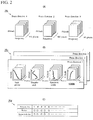
- FIG. 2 shows explanatory diagrams each illustrating a configuration of data, in which FIG. 2 (A) shows a configuration diagram of the spectrum FIFO bank 25b, FIG. 2 (B) shows a configuration diagram of the parameter FIFO bank 25c, and FIG. 2 (C) shows a configuration diagram of the number of valid data FIFO bank 25d.
- the spectrum FIFO bank 25b stores NS pieces of information on altitude and frequency separately for each beam direction.
- the spectrum FIFO bank 25b adds newly acquired data, and when the data exceed NS pieces, deletes the data in chronological order. Thus, consistently new NS pieces of spectrum data are stored in the spectrum FIFO bank 25b.
- the parameter FIFO bank 25c stores NP pieces of data respectively for altitude and peak power, altitude and Doppler shift, altitude and spectrum width, and altitude and SQSUM separately for each beam direction.
- the parameter FIFO bank 25c also adds newly acquired data, and when the data exceed NP pieces, deletes the data in chronological order. Thus, consistently new NP pieces of parameter data are stored in the parameter FIFO bank 25c.
- the number-of-valid-data FIFO bank 25d stores validity or invalidity of data acquired in the past separately for each beam number.
- the number-of-valid-data FIFO bank 25d stores validity or invalidity of data from the latest one in order, such as the last data, second to the last data, and adds data as needed when there is new data. Therefore, validity of a plurality of data are stored consistently from new ones separately for each beam number in the number-of-valid-data FIFO bank 25d.
- FIG. 3 is a functional block diagram illustrating functions which the control unit 21 of the analysis device 3 executes according to the analysis program 25a
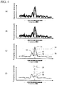
- FIG. 4 is an explanatory diagram illustrating data processing under analysis. Further, the processing by the functional blocks shown in FIG. 3 is executed on a range basis defined by direction and distance, and is repeated for all ranges.
- a data inspection unit 31 acquires spectrum data from the reflected light data for inspecting. That is, the data inspection unit 31 continues the process when the reflected light data are valid data to allow the data to be stored, and when missing of observation exists more than a predetermined amount in the reflected light data and when there are no data, the data are not stored in the spectrum FIFO bank 25b, the parameter FIFO bank 25c, and the number of valid data FIFO bank 25d.
- the data inspection unit 31 proceeds the process to a valid parameter data calculation unit 34 when there is no problem in the spectrum data of the reflected light data, and otherwise, proceeds the process to a noise level estimation unit 32.
- the noise level estimation unit 32 estimates a level of noise existing in the spectrum data of the reflected light data. This noise level estimation may be done by appropriate methods such as by estimating based on a predetermined value, or a region having peaks of predetermined numbers or more is estimated as the noise level.
- An average spectrum intensity estimation unit 33 estimates average spectrum intensity from the acquired spectrum of the reflected light data. This estimation may be done by appropriate method such as by estimating in advance from past data, or estimating by acquiring an average value of spectrum intensities from the present data.
- the valid parameter data calculation unit 34 calculates valid parameters from the spectrum data of the reflected light data. These parameters may be appropriate parameters such as altitude and peak power, altitude and Doppler shift, altitude and spectrum width, and altitude and SQUS etc.
- the valid parameter data calculation unit 34 which has thus calculated the parameters passes the process to an initial fitting value estimation unit 35 for estimating an initial fitting value.
- the initial fitting value estimation unit 35 has an estimation method determination unit 36, an unit for estimating initial value from spectrum 37 (spectrum initial value estimation process), an unit for estimating initial value from parameters 38 (parameter initial value estimation process), and a re-estimation necessity determination unit 39 (fitting do-over determination unit).
- the estimation method determination unit 36 determines as that, from which the initial value should be determined; from the spectrum or from the parameters. Specifically, if the number of peaks in the spectrum of the previous observation data (or average data of a plurality of observation data) stored in the spectrum FIFO bank 25b is at a predetermined number or less (for example, 1 or less), the initial value is determined to be estimated from the spectrum of the previous observation data, and otherwise, the initial value is determined from the parameters of the previous observation data.
- a predetermined number or less for example, 1 or less
- the unit for estimating initial value from spectrum 37 estimates the initial value from the spectrum of average data of a plurality of past observation data. In this initial value estimation, the spectrum is assumed as the initial value without any change.
- the observation data averaged here may be predetermined numbers of data from the most recent one, and may be all observation data stored in the spectrum FIFO bank 25b.
- the unit for estimating initial value from parameters 38 estimates the initial value from average values of parameters of a plurality of observation data stored in the parameter FIFO bank 25c.
- each of average values of parameters of predetermined number of times from the most recent one may be assumed as the initial value, and may be the average value of all data of the parameter FIFO bank 25c.
- the estimation of the initial value from the most recent observation data by the unit for estimating initial value from spectrum 37 or the unit for estimating initial value from parameters 38 allows realizing an appropriate analysis utilizing a fact that the condition of atmosphere does not change so much as long as the position (spot) is the same.
- the re-estimation necessity determination unit 39 determines whether the initial value estimated by the unit for estimating initial value from spectrum 37 or the unit for estimating initial value from parameters 38 is appropriate or not, and adopts the value without any change when appropriate, and does over the estimation when it is inappropriate. Specifically, when the initial value estimated from the parameters is not in a predetermined allowable extent or the number of peaks in the initial value estimated from the spectrum is not in predetermined allowable numbers, the process is returned to the estimation method determination unit 36, and the process is done over.
- a fitting execution unit 41 (fitting processing unit) executes fitting using the determined initial value. This fitting may be done by an existing appropriate fitting process, and this example uses a Gaussian fitting where a least-square method is used.
- the spectrum of reflected light data in a certain direction at a certain time shows a rough spectrum with noise.
- FIG. 4 (B) by performing a fitting process using the initial value for smoothing, a spectrum with less roughness can be obtained as shown in FIG. 4 (C) .
- the appropriate fitting is performed.
- transmission frequency of a laser light shows reflection from scattering bodies which are not moving, and the rest of frequencies show reflection from scattering bodies which are moving.
- FIG. 4 (A) shows the spectrum of reflected light in a direction where an obstacle exists, and when smoothed, two peaks, 51 and 52 appear as shown in FIG. 4 (C) .
- the obstacle includes a structure such as a building, and/or a flying object such as a bird or an UAV (uninhabited airborne vehicle), and it indicates a solid body of a visible size.
- the peak 51 is represented as an extremely strong steep peak at a frequency identical with the transmission frequency as shown in the figure.
- the peak 51 appears as an extremely strong steep peak at an arbitrary frequency, and this peak moves according to movement of the flying object continuously in terms of time. That is, when the spectrum in a certain direction at a certain distance is represented as a spectrum of a certain range, a similar steep peak 51 appears in an adjacent range as time passes.
- the peak 51 by such obstacle is unnecessary, and what is necessary is information of the second highest peak 52.
- the peak 52 is shown for that a Doppler shift due to aerosol moving by wind is detected, and this needs to be acquired accurately.
- this actually necessary area around the peak 52 can be fitted as the initial value of the fitting.
- a fitting result examination unit 42 examines whether the result of the fitting is appropriate or not, and proceeds to the next process if appropriate, but if it is inappropriate, returns the process to the valid parameter data calculation unit 34 or the fitting execution unit 41 depending on the content.
- the process is returned to the fitting execution unit 41 to do-over the fitting.
- the fitting is done-over by assuming an average spectrum of the rest of the observation data, in which the oldest observation datum (spectrum) is reduced, as the initial value.
- the fitting is done-over by assuming an average parameter of the rest of the observation data, in which the oldest observation datum (parameter) is reduced, as the initial value.
- the maximum allowable value 54 is preferably assumed as a maximum value of the peak 52 originating from aerosol (that is, a peak excluding the peak 51 originating from an obstacle) in the past observation data, or a value close to such value, or alternatively a value a little lower than the peak value originating from an obstacle.
- it can be set for example within an extent ⁇ 20 % of the maximum value, preferably set within an extent ⁇ 10 % thereof, and appropriately set within an extent ⁇ 5 % thereof.
- the peak value originating from an obstacle preferably the past average value, and may be the maximum peak value or the minimum peak value
- it can be set within an extent - 20 % from the peak value originating from an obstacle, preferably set within an extent - 10 % therefrom, and appropriately set within an extent - 5 % therefrom. In this example, it is set as the value - 5 % of the past average value of the peak value originating from an obstacle.
- the fitting result examination unit 42 is configured such that when the value of fitted peak 52 is larger than the predetermined maximum allowable value 54, the process is returned to the fitting execution unit 41, but not limited hereto, the process may be returned to the fitting execution unit 41 when the fitted peak 52 is away from a peak position of the last observation data by a predetermined amount or more. In such case, when the fitting is too far, the process to do-over the fitting can be realized, and a more appropriate fitting can be executed.
- the minimum allowable value 55 here may be a noise level determined from the past observation data, or a value close to the noise level.
- the value close to the noise level may be within an extent + 20 % from the noise level (preferably, past average value, and may be the maximum value or the minimum value), preferably within an extent + 10 % therefrom, and appropriately within an extent + 5% therefrom. In this example, it is set as the value + 5 % of the past average value of the noise level.
- a result smoothing unit 43 (unit for determining peak originating from an obstacle, unit for excluding peak originating from an obstacle) removes the peak 51 originating from an obstacle shown in FIG.4 (C) as shown in FIG. 4 (D) .
- the result smoothing unit 43 scans the spectrum from a peak center (in the illustrated example, it is the transmission frequency of 80 MHz, but in the case of the obstacle originating from a flying object, it becomes a frequency different from the transmission frequency) to a high frequency side and a low frequency side to look for a tilt steeper than a predetermined obstacle-originating determination tilt value.
- the determination as being the peak 51 originating from an obstacle may be made only when either of the followings is satisfied; (1) a peak exists within frequencies of a predetermined extent from the transmission frequency of a laser light, or (2) there is a similar steep peak in an adjacent range measured at an adjacent time.
- the peak 51 originating from an obstacle can be detected more accurately.
- the adjacent time may be 10 minutes or less, preferably 5 minutes or less, more preferably 1 minute or less, further preferably 30 seconds or less, and appropriately 10 seconds or less.
- the adjacent range is away by preferably 10 ranges or less, more preferably 5 ranges or less, further preferably 3 ranges or less, and appropriately 1 range or less, in terms of direction, distance and height, respectively.
- the result smoothing unit 43 also executes a singularity correcting process performing correction when results seen on a range basis are inappropriate. Particularly, since the condition of atmosphere changes similarly in close regions, it does not differ much between neighboring ranges (or at adjacent ranges in a predetermined extent), that is, at a neighboring direction and/or a neighboring distance and/or a neighboring height.
- the Doppler lidar 2 despite that one neighboring data (data neighboring on nearer distance, neighboring on one direction, or neighboring on one height) and the other neighboring data (data neighboring on farer distance, neighboring on the other direction, or neighboring on the other height) are of similar values, when data in a range therebetween is not similar, the data in this range is removed and changed instead to intermediate values between the data neighboring on near distance and the data neighboring on far distance by interpolation.
- the data compared and interpolated here may be appropriate data such as a peak value, or wind information such as wind velocity.
- a data storage unit 44 adds the spectrum, in which the peak 51 originating from an obstacle is cut, to the spectrum FIFO bank 25b as the observation data, adds the parameters acquired by the valid parameter data calculation unit 34 to the parameter FIFO bank 25c, and adds validity/invalidity of each of the data to the number of valid data FIFO bank 25d, to store the latest data. Further, in addition to these FIFO banks, it is preferable to accumulate same data (spectra and parameters) in an appropriate data base. The past observation data can be accumulated thereby, and past information deleted from the spectrum FIFO bank 25b and/or the parameter FIFO bank 25c can also be referred to.
- the above described re-estimation necessity determination unit 39 extracts clutter data by a clutter data extraction unit 45 as a process for display.
- the clutter data by a structure and/or a flying object can be extracted thereby.
- a stationary object identification unit 46 identifies a stationary object (obstacle) from a clutter extracted by the above described clutter data extraction unit 45. That is, since the position where the clutter exists is the position where the structure or the flying object exists, the stationary object is identified and displayed to allow for easy understanding by users.
- a monitor output unit 47 displays the observed spectrum data etc. on a display unit 24 (refer to FIG. 1 ) for monitoring with the position of the stationary object identified by the above described stationary object identification unit 46.
- the wind condition such as wind velocity and the position of an obstacle object such as a building can be superimposed for display, and allows users to understand easily.
- the Doppler shift of aerosol can be detected with a high degree of accuracy.
- the peak originating from an obstacle can be determined, it is possible to exclude the peak originating from an obstacle, and extract and detect the effect of aerosol only.
- the spectrum of the observation data is stored with the peak originating from an obstacle being removed, and thus, the observation data in which the effect of the obstacle is excluded can be used. Also, by performing the fitting using such observation data, the peak originating from aerosol is appropriately fitted, not performing fitting to the peak of the obstacle, and thus, detection can be done with accuracy.
- the peak originating from an obstacle may be adopted as the first peak, or the second peak may be adopted uniformly in an attempt to avoid the peak of the obstacle, resulting in missing an important peak at a portion where there is no obstacle, but the peak originating from aerosol can be appropriately detected without such problems.
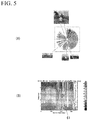
- this reflected light data is shown by a graph in which the vertical axis is distance (km), and the horizontal axis is angle of direction (degree), and color is data acquisition rate (%) as shown in FIG. 5 (B) , the value at a portion before an obstacle-existing position 61 where the obstacle exists (near distance portion) is unnaturally dropped, and it is understood as inappropriate data.
- the effect of the obstacle can be excluded to appropriately detect the Doppler shift due to aerosol at a position before the obstacle. Therefore, the wind condition such as wind velocity and/or wind direction can be measured with accuracy.
- an echo due to aerosol can be analyzed by a fitting operation with the least-square method in a process of deriving wind velocity from the Doppler lidar 2.
- an averaging process of a plurality of spectrum data from preliminary observation in the same direction, by the average spectrum intensity estimation unit 33 allows peak-searching by the initial fitting value estimation unit 35 after the noise level is reduced to determine the initial value of the least-square method for performing the fitting, and a real time analysis can be realized with a high degree of accuracy.
- the fitting process can be done by assuming the last fitting result as the initial value. With the initial value of the fitting being past data after the fitting, a result more appropriate than when the reflected light data is directly assumed as the initial value can be acquired.
- this analysis approach allows a low SNR, and the data acquisition with a high degree of accuracy becomes available in a far region of 10 km or more where data has conventionally been omitted for quality control.
- the maximum observation distance of 30 km can be realized, and the available observation extent can be made ten times as much as the conventional products.
- such analysis may be configured such that a real time processing is performed on FPGA and/or the cloud, and a data quality control by a median filter is performed to store observation results for graphical display.
- a similar operational effect can be provided in this case as well.
- the Doppler lidar 2 and the analysis device 3 are configured separately, but the Doppler lidar 2 and the analysis device 3 may be configured as being placed in a housing as one device. The same operational effect can be provided in this case as well.
- the spectrum and the parameters stored in the data storage unit 44 can be used to allow for being utilized as a wind condition observation device for observing wind conditions such as wind velocity and/or wind directions. It is thereby possible to observe the wind condition to be utilized for various usages such as for weather forecasting, for observation of wind condition of areas where aircrafts fly and security at the time of their taking-off and landing, for calculating appropriate spots as installation sites of wind power generators etc.
- the present invention can be used for various industries which use wind conditions such as an industry which calculates appropriate installation sites of wind power generators, an industry which observes air streams for secure operation of aircrafts, an industry of weather forecasting etc.
Landscapes
- Engineering & Computer Science (AREA)
- Physics & Mathematics (AREA)
- General Physics & Mathematics (AREA)
- Computer Networks & Wireless Communication (AREA)
- Radar, Positioning & Navigation (AREA)
- Remote Sensing (AREA)
- Electromagnetism (AREA)
- Multimedia (AREA)
- Aviation & Aerospace Engineering (AREA)
- Optical Radar Systems And Details Thereof (AREA)
- Radar Systems Or Details Thereof (AREA)
Applications Claiming Priority (1)
| Application Number | Priority Date | Filing Date | Title |
|---|---|---|---|
| PCT/JP2016/066085 WO2017208375A1 (fr) | 2016-05-31 | 2016-05-31 | Dispositif d'analyse par décalage doppler |
Publications (2)
| Publication Number | Publication Date |
|---|---|
| EP3467543A1 true EP3467543A1 (fr) | 2019-04-10 |
| EP3467543A4 EP3467543A4 (fr) | 2020-01-15 |
Family
ID=60479394
Family Applications (1)
| Application Number | Title | Priority Date | Filing Date |
|---|---|---|---|
| EP16904000.3A Pending EP3467543A4 (fr) | 2016-05-31 | 2016-05-31 | Dispositif d'analyse par décalage doppler |
Country Status (5)
| Country | Link |
|---|---|
| US (1) | US10816668B2 (fr) |
| EP (1) | EP3467543A4 (fr) |
| JP (1) | JP6562583B2 (fr) |
| CN (1) | CN109154658B (fr) |
| WO (1) | WO2017208375A1 (fr) |
Cited By (1)
| Publication number | Priority date | Publication date | Assignee | Title |
|---|---|---|---|---|
| EP3985417A4 (fr) * | 2019-08-08 | 2023-07-05 | Japan Aerospace Exploration Agency | Dispositif d'observation de flux d'air à distance, procédé d'observation de flux d'air à distance et programme |
Families Citing this family (31)
| Publication number | Priority date | Publication date | Assignee | Title |
|---|---|---|---|---|
| US10257728B2 (en) | 2013-03-15 | 2019-04-09 | DGS Global Systems, Inc. | Systems, methods, and devices for electronic spectrum management |
| US10271233B2 (en) | 2013-03-15 | 2019-04-23 | DGS Global Systems, Inc. | Systems, methods, and devices for automatic signal detection with temporal feature extraction within a spectrum |
| US10237770B2 (en) | 2013-03-15 | 2019-03-19 | DGS Global Systems, Inc. | Systems, methods, and devices having databases and automated reports for electronic spectrum management |
| US10244504B2 (en) | 2013-03-15 | 2019-03-26 | DGS Global Systems, Inc. | Systems, methods, and devices for geolocation with deployable large scale arrays |
| US10257727B2 (en) | 2013-03-15 | 2019-04-09 | DGS Global Systems, Inc. | Systems methods, and devices having databases and automated reports for electronic spectrum management |
| US10219163B2 (en) | 2013-03-15 | 2019-02-26 | DGS Global Systems, Inc. | Systems, methods, and devices for electronic spectrum management |
| US10231206B2 (en) | 2013-03-15 | 2019-03-12 | DGS Global Systems, Inc. | Systems, methods, and devices for electronic spectrum management for identifying signal-emitting devices |
| US12256233B2 (en) | 2013-03-15 | 2025-03-18 | Digital Global Systems, Inc. | Systems and methods for automated financial settlements for dynamic spectrum sharing |
| US11646918B2 (en) | 2013-03-15 | 2023-05-09 | Digital Global Systems, Inc. | Systems, methods, and devices for electronic spectrum management for identifying open space |
| US9078162B2 (en) | 2013-03-15 | 2015-07-07 | DGS Global Systems, Inc. | Systems, methods, and devices for electronic spectrum management |
| US12356206B2 (en) | 2013-03-15 | 2025-07-08 | Digital Global Systems, Inc. | Systems and methods for automated financial settlements for dynamic spectrum sharing |
| US10299149B2 (en) | 2013-03-15 | 2019-05-21 | DGS Global Systems, Inc. | Systems, methods, and devices for electronic spectrum management |
| US10257729B2 (en) | 2013-03-15 | 2019-04-09 | DGS Global Systems, Inc. | Systems, methods, and devices having databases for electronic spectrum management |
| US12183213B1 (en) | 2017-01-23 | 2024-12-31 | Digital Global Systems, Inc. | Unmanned vehicle recognition and threat management |
| US10700794B2 (en) | 2017-01-23 | 2020-06-30 | Digital Global Systems, Inc. | Systems, methods, and devices for automatic signal detection based on power distribution by frequency over time within an electromagnetic spectrum |
| US12205477B2 (en) | 2017-01-23 | 2025-01-21 | Digital Global Systems, Inc. | Unmanned vehicle recognition and threat management |
| US10459020B2 (en) | 2017-01-23 | 2019-10-29 | DGS Global Systems, Inc. | Systems, methods, and devices for automatic signal detection based on power distribution by frequency over time within a spectrum |
| US10529241B2 (en) | 2017-01-23 | 2020-01-07 | Digital Global Systems, Inc. | Unmanned vehicle recognition and threat management |
| US10498951B2 (en) | 2017-01-23 | 2019-12-03 | Digital Global Systems, Inc. | Systems, methods, and devices for unmanned vehicle detection |
| US10690773B2 (en) * | 2017-12-07 | 2020-06-23 | Velodyne Lidar, Inc. | Systems and methods for efficient multi-return light detectors |
| JP6822667B2 (ja) * | 2017-12-13 | 2021-01-27 | メトロウェザー株式会社 | ドップラーライダー装置、及び乱気流警報システム |
| US10943461B2 (en) | 2018-08-24 | 2021-03-09 | Digital Global Systems, Inc. | Systems, methods, and devices for automatic signal detection based on power distribution by frequency over time |
| CN109738212B (zh) * | 2019-01-24 | 2020-11-06 | 安徽大学 | 一种以频谱峭度为优化指标的自适应多普勒矫正方法 |
| JP7164613B2 (ja) * | 2019-04-08 | 2022-11-01 | 三菱電機株式会社 | 風計測ライダ装置 |
| WO2021005634A1 (fr) * | 2019-07-05 | 2021-01-14 | 三菱電機株式会社 | Dispositif de détection de turbulence et procédé de détection de turbulence |
| JP7597367B2 (ja) | 2021-03-17 | 2024-12-10 | 国立研究開発法人宇宙航空研究開発機構 | 気流計測装置、気流計測方法及び気流計測プログラム |
| CN113552593B (zh) * | 2021-07-21 | 2023-12-29 | 北京理工大学 | 荧光激光雷达障碍物排除方法 |
| CN113536686B (zh) * | 2021-07-23 | 2022-11-01 | 河北工业大学 | 一种风速的概率模型的建模方法 |
| CN114152596B (zh) * | 2021-11-30 | 2024-01-12 | 西华大学 | 一种基于陡峭度参数测量大气湍流广义指数参数的方法及装置 |
| CN114994636B (zh) * | 2022-06-23 | 2025-05-09 | 中国电子科技集团公司第十一研究所 | 一种激光雷达数据处理方法及装置 |
| JP7403889B1 (ja) | 2023-03-28 | 2023-12-25 | 日本気象株式会社 | 光学式遠隔気流計測装置を用いた方法、及び風況観測システム |
Family Cites Families (10)
| Publication number | Priority date | Publication date | Assignee | Title |
|---|---|---|---|---|
| US5563604A (en) * | 1995-02-08 | 1996-10-08 | Alliedsignal Inc. | Weather radar using spectral gaussian envelope discrimination for clutter rejection |
| US5568151A (en) * | 1995-05-17 | 1996-10-22 | Merritt; David A. | Statistical averaging method for wind profiler doppler spectra |
| US6307500B1 (en) * | 1999-08-13 | 2001-10-23 | University Corporation For Atmospheric Research | Method of moment estimation and feature extraction for devices which measure spectra as a function of range or time |
| JP3794361B2 (ja) * | 2002-08-28 | 2006-07-05 | 三菱電機株式会社 | レーダ信号処理装置及びレーダ信号処理方法 |
| JP3944130B2 (ja) | 2003-07-08 | 2007-07-11 | 三菱電機株式会社 | 移動体のレ−ダ方式、レ−ダ装置、レーダ信号処理方法、及びレーダ信号処理装置 |
| JP2008014837A (ja) * | 2006-07-06 | 2008-01-24 | Toshiba Corp | レーダ装置とその信号処理方法 |
| CN101825711A (zh) * | 2009-12-24 | 2010-09-08 | 哈尔滨工业大学 | 一种2μm全光纤相干激光多普勒测风雷达系统 |
| CN101819275B (zh) * | 2010-04-20 | 2012-10-10 | 中国海洋大学 | 测量多气象参数的多普勒激光雷达装置 |
| JP5717174B2 (ja) * | 2010-11-08 | 2015-05-13 | 独立行政法人 宇宙航空研究開発機構 | 遠隔乱気流検知方法及びそれを実施する装置 |
| CN105245584B (zh) * | 2015-09-25 | 2018-06-15 | 北京航空航天大学 | 一种基于ofdm雷达通信一体化的车联网感知系统及其构建方法 |
-
2016
- 2016-05-31 US US16/306,359 patent/US10816668B2/en active Active
- 2016-05-31 WO PCT/JP2016/066085 patent/WO2017208375A1/fr not_active Ceased
- 2016-05-31 JP JP2018520265A patent/JP6562583B2/ja active Active
- 2016-05-31 CN CN201680085867.9A patent/CN109154658B/zh active Active
- 2016-05-31 EP EP16904000.3A patent/EP3467543A4/fr active Pending
Cited By (1)
| Publication number | Priority date | Publication date | Assignee | Title |
|---|---|---|---|---|
| EP3985417A4 (fr) * | 2019-08-08 | 2023-07-05 | Japan Aerospace Exploration Agency | Dispositif d'observation de flux d'air à distance, procédé d'observation de flux d'air à distance et programme |
Also Published As
| Publication number | Publication date |
|---|---|
| JPWO2017208375A1 (ja) | 2019-03-28 |
| EP3467543A4 (fr) | 2020-01-15 |
| US20190346571A1 (en) | 2019-11-14 |
| CN109154658B (zh) | 2020-06-09 |
| US10816668B2 (en) | 2020-10-27 |
| WO2017208375A1 (fr) | 2017-12-07 |
| JP6562583B2 (ja) | 2019-08-21 |
| CN109154658A (zh) | 2019-01-04 |
Similar Documents
| Publication | Publication Date | Title |
|---|---|---|
| US10816668B2 (en) | Doppler shift analysis device | |
| CN113504525B (zh) | 一种雾区能见度反演方法及系统 | |
| EP1749219B1 (fr) | Dispositif de radar a laser et procede correspondant | |
| JP2805249B2 (ja) | マイクロ波レーダを使用するマイクロバースト前兆検出方法及び装置 | |
| US6081220A (en) | Radar system for observing weather phenomena with improved radar system parameters | |
| KR100922130B1 (ko) | 도플러 기상레이더의 이차 에코 제거 방법 | |
| Ryde et al. | Performance of laser and radar ranging devices in adverse environmental conditions | |
| Gossart et al. | Blowing snow detection from ground-based ceilometers: application to East Antarctica | |
| CN109471098B (zh) | 利用fod雷达相位相干性信息的机场跑道异物检测方法 | |
| US8305261B2 (en) | Adaptive mainlobe clutter method for range-Doppler maps | |
| KR101244544B1 (ko) | 단일 및 이중편파 레이더 변수의 샘플링오차 품질지수 산출 방법 | |
| EP3367125A1 (fr) | Dispositif de mesure de vent | |
| CN110006848A (zh) | 一种获取气溶胶消光系数的方法和装置 | |
| US20090167596A1 (en) | Method of processing a radar image | |
| CN109581384B (zh) | 基于多普勒天气雷达的晴空垂直风廓线探测方法及系统 | |
| EP3729132B1 (fr) | Production de cartes de déformation de pente | |
| JP3702347B2 (ja) | ウィンドプロファイラにおける信号処理方法及びそのプログラムと装置 | |
| EP3985417B1 (fr) | Dispositif d'observation de flux d'air à distance, procédé d'observation de flux d'air à distance et programme | |
| Gryning et al. | Measurement methodologies for wind energy based on ground-level remote sensing | |
| Jang et al. | Rainfall observation system using automotive radar sensor for ADAS based driving safety | |
| JP6983960B2 (ja) | 信号処理装置及び信号処理方法 | |
| Jin et al. | Suppression of precipitation bias on wind velocity from continuous-wave Doppler lidars | |
| CN111046765A (zh) | 一种用于高铁的危险预警方法和系统 | |
| Wassaf et al. | Wake vortex tangential velocity adaptive spectral (TVAS) algorithm for pulsed Lidar systems | |
| KR20170044237A (ko) | 해양 레이더를 이용하여 국지 강수를 추정하는 시스템 및 그 추정방법 |
Legal Events
| Date | Code | Title | Description |
|---|---|---|---|
| STAA | Information on the status of an ep patent application or granted ep patent |
Free format text: STATUS: THE INTERNATIONAL PUBLICATION HAS BEEN MADE |
|
| PUAI | Public reference made under article 153(3) epc to a published international application that has entered the european phase |
Free format text: ORIGINAL CODE: 0009012 |
|
| STAA | Information on the status of an ep patent application or granted ep patent |
Free format text: STATUS: REQUEST FOR EXAMINATION WAS MADE |
|
| 17P | Request for examination filed |
Effective date: 20181219 |
|
| AK | Designated contracting states |
Kind code of ref document: A1 Designated state(s): AL AT BE BG CH CY CZ DE DK EE ES FI FR GB GR HR HU IE IS IT LI LT LU LV MC MK MT NL NO PL PT RO RS SE SI SK SM TR |
|
| AX | Request for extension of the european patent |
Extension state: BA ME |
|
| RIN1 | Information on inventor provided before grant (corrected) |
Inventor name: FURUMOTO, JUNICHI |
|
| DAV | Request for validation of the european patent (deleted) | ||
| DAX | Request for extension of the european patent (deleted) | ||
| A4 | Supplementary search report drawn up and despatched |
Effective date: 20191216 |
|
| RIC1 | Information provided on ipc code assigned before grant |
Ipc: G01S 17/95 20060101ALI20191210BHEP Ipc: G01P 5/26 20060101ALI20191210BHEP Ipc: G01S 17/58 20060101AFI20191210BHEP |
|
| RAP1 | Party data changed (applicant data changed or rights of an application transferred) |
Owner name: METROWEATHER CO., LTD. |
|
| STAA | Information on the status of an ep patent application or granted ep patent |
Free format text: STATUS: EXAMINATION IS IN PROGRESS |
|
| 17Q | First examination report despatched |
Effective date: 20201009 |
|
| RAP3 | Party data changed (applicant data changed or rights of an application transferred) |
Owner name: METROWEATHER CO., LTD. |