EP3467564A2 - Télescope électronique - Google Patents
Télescope électronique Download PDFInfo
- Publication number
- EP3467564A2 EP3467564A2 EP18195410.8A EP18195410A EP3467564A2 EP 3467564 A2 EP3467564 A2 EP 3467564A2 EP 18195410 A EP18195410 A EP 18195410A EP 3467564 A2 EP3467564 A2 EP 3467564A2
- Authority
- EP
- European Patent Office
- Prior art keywords
- eyepiece
- lens
- electronic telescope
- disposed
- main body
- Prior art date
- Legal status (The legal status is an assumption and is not a legal conclusion. Google has not performed a legal analysis and makes no representation as to the accuracy of the status listed.)
- Withdrawn
Links
Images

Classifications
-
- F—MECHANICAL ENGINEERING; LIGHTING; HEATING; WEAPONS; BLASTING
- F21—LIGHTING
- F21V—FUNCTIONAL FEATURES OR DETAILS OF LIGHTING DEVICES OR SYSTEMS THEREOF; STRUCTURAL COMBINATIONS OF LIGHTING DEVICES WITH OTHER ARTICLES, NOT OTHERWISE PROVIDED FOR
- F21V19/00—Fastening of light sources or lamp holders
- F21V19/001—Fastening of light sources or lamp holders the light sources being semiconductors devices, e.g. LEDs
- F21V19/003—Fastening of light source holders, e.g. of circuit boards or substrates holding light sources
-
- G—PHYSICS
- G02—OPTICS
- G02B—OPTICAL ELEMENTS, SYSTEMS OR APPARATUS
- G02B23/00—Telescopes, e.g. binoculars; Periscopes; Instruments for viewing the inside of hollow bodies; Viewfinders; Optical aiming or sighting devices
-
- G—PHYSICS
- G02—OPTICS
- G02B—OPTICAL ELEMENTS, SYSTEMS OR APPARATUS
- G02B23/00—Telescopes, e.g. binoculars; Periscopes; Instruments for viewing the inside of hollow bodies; Viewfinders; Optical aiming or sighting devices
- G02B23/12—Telescopes, e.g. binoculars; Periscopes; Instruments for viewing the inside of hollow bodies; Viewfinders; Optical aiming or sighting devices with means for image conversion or intensification
-
- G—PHYSICS
- G02—OPTICS
- G02B—OPTICAL ELEMENTS, SYSTEMS OR APPARATUS
- G02B25/00—Eyepieces; Magnifying glasses
- G02B25/001—Eyepieces
-
- G—PHYSICS
- G02—OPTICS
- G02B—OPTICAL ELEMENTS, SYSTEMS OR APPARATUS
- G02B7/00—Mountings, adjusting means, or light-tight connections, for optical elements
- G02B7/02—Mountings, adjusting means, or light-tight connections, for optical elements for lenses
- G02B7/04—Mountings, adjusting means, or light-tight connections, for optical elements for lenses with mechanism for focusing or varying magnification
- G02B7/06—Focusing binocular pairs
-
- F—MECHANICAL ENGINEERING; LIGHTING; HEATING; WEAPONS; BLASTING
- F21—LIGHTING
- F21Y—INDEXING SCHEME ASSOCIATED WITH SUBCLASSES F21K, F21L, F21S and F21V, RELATING TO THE FORM OR THE KIND OF THE LIGHT SOURCES OR OF THE COLOUR OF THE LIGHT EMITTED
- F21Y2105/00—Planar light sources
- F21Y2105/10—Planar light sources comprising a two-dimensional [2D] array of point-like light-generating elements
-
- F—MECHANICAL ENGINEERING; LIGHTING; HEATING; WEAPONS; BLASTING
- F21—LIGHTING
- F21Y—INDEXING SCHEME ASSOCIATED WITH SUBCLASSES F21K, F21L, F21S and F21V, RELATING TO THE FORM OR THE KIND OF THE LIGHT SOURCES OR OF THE COLOUR OF THE LIGHT EMITTED
- F21Y2115/00—Light-generating elements of semiconductor light sources
- F21Y2115/10—Light-emitting diodes [LED]
-
- G—PHYSICS
- G02—OPTICS
- G02B—OPTICAL ELEMENTS, SYSTEMS OR APPARATUS
- G02B23/00—Telescopes, e.g. binoculars; Periscopes; Instruments for viewing the inside of hollow bodies; Viewfinders; Optical aiming or sighting devices
- G02B23/16—Housings; Caps; Mountings; Supports, e.g. with counterweight
- G02B23/18—Housings; Caps; Mountings; Supports, e.g. with counterweight for binocular arrangements
-
- H—ELECTRICITY
- H04—ELECTRIC COMMUNICATION TECHNIQUE
- H04N—PICTORIAL COMMUNICATION, e.g. TELEVISION
- H04N25/00—Circuitry of solid-state image sensors [SSIS]; Control thereof
- H04N25/70—SSIS architectures; Circuits associated therewith
- H04N25/71—Charge-coupled device [CCD] sensors; Charge-transfer registers specially adapted for CCD sensors
Definitions
- the application relates in general to an electronic telescope, and in particular to an electronic telescope that includes a single eyepiece lens.
- an embodiment of the invention provides an electronic telescope, including a main body, a lens module, a display module, and a single eyepiece.
- the main body includes an objective end and an eyepiece end which is opposite to the objective end.
- the lens module is disposed on the objective end.
- the display module connects to the lens module and is configured to show an image captured from the lens module.
- the single eyepiece lens with a single focus has a longitudinal structure and is disposed on the eyepiece end, wherein the eyepiece lens corresponds to the two eyes of the user.
- the eyepiece lens is a convex lens and has a first side and an opposite second side, the first side is farther away from the display module than the second side is, and the radius of curvature of the eyepiece lens on the first side has a range of 280 mm to 330 mm. In some embodiments, the radius of curvature of the eyepiece lens on the second side has a range of 100 mm to 150 mm.
- the electronic telescope further comprises an infrared light-emitting diode (LED) assembly, disposed on the objective end and adjacent to the lens module.
- the LED assembly includes a plurality of light-emitting diodes, and the light-emitting diodes are arranged in a matrix.
- the electronic telescope further comprises a circuit board disposed in the main body, wherein the lens module and the LED assembly are disposed on the circuit board, and the length of the lens module is greater than the length of the circuit board in the direction of the central axis of the main body.
- the circuit board connects the lens module to the display, and a charge-coupled device is disposed on the circuit board.
- the main body further has an observation room situated between the objective end and the eyepiece end.
- the observation room has a tapered structure with a first end and a second end respectively corresponding to the objective end and an eyepiece end, and an opening of the observation room is narrower on the first end than on the second end.
- the observation room includes a first inner wall and a second inner wall which are facing each other, and the first and second inner walls extend aslant with respect to a central axis of the main body from the objective end to the eyepiece end.
- the first and the second walls include a plurality of scattering structures.
- the electronic telescope further comprises an adjusting wheel configured to adjust the focus of the lens module, and the adjusting wheel is disposed on the bottom of the main body.
- the upper surface of the main body has a plurality of protrusions.
- the electronic telescope further comprises an eyeshield disposed on the eyepiece end, wherein the length of the eyeshield in the long axis direction is at least 30 mm longer than the length of the eyepiece lens.
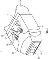
- Fig. 1 is a schematic diagram of an electronic telescope 1 according to an embodiment of the invention
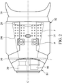
- Fig. 2 is a top view diagram of the electronic telescope 1.
- the electronic telescope 1 for example, may be a night version telescope, primarily comprising a main body 10, a single eyepiece lens 20, a lens module 30, a light-emitting diode (LED) assembly 40, and a display module 50.
- the main body 10 includes an objective end S1 and an eyepiece end S2 which are opposite each other.
- the lens module 30 and the LED assembly 40 are disposed on the objective end S1, and the eyepiece lens 20 is disposed on the eyepiece end S2.
- the display module 50 is disposed in the main body 10, and a circuit board F (such as a flexible printed circuit board (FPCB), and a complementary metal-oxide-semiconductor device (CMOS) or a charge-coupled device (CCD) may be disposed thereon) connects and is between the lens module 30 and the display module 50.
- a circuit board F such as a flexible printed circuit board (FPCB), and a complementary metal-oxide-semiconductor device (CMOS) or a charge-coupled device (CCD) may be disposed thereon
- CMOS complementary metal-oxide-semiconductor device
- CCD charge-coupled device
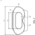
- Fig. 3 is a rear-view diagram illustrating the electronic telescope 1 in Fig. 1 .
- the eyepiece lens 20 has a longitudinal structure and a large area which can fully cover both of the user's eyes, so that it can easily correspond to the eyes of any user.
- the electronic telescope 1 is convenient for any user to use (without having to adjust interpupillary distance), and additional components such as adjustment mechanisms for interpupillary distance can be eliminated, simplifying the manufacturing processes and lowering the production cost.
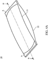
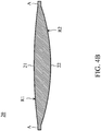
- Figs. 4A and 4B are schematic diagrams of the eyepiece lens 20 in Fig. 3 .
- the eyepiece lens 20, which may be a convex lens, has a first side 21 and an opposite second side 22.
- the first side 21 is farther away from the display module 50 than the second side 22 is (that is, the first side 21 is closer to the eyes of the user when the electronic telescope 1 is being used).
- the radius of curvature R1 of the eyepiece lens on the first side 21 has a range of 280 mm to 330 mm; in a preferred embodiment, the radius of curvature R1 is 307 mm.
- the radius of curvature R2 of the eyepiece lens on the second side 22 has a range of 100 mm to 150 mm; in a preferred embodiment, the radius of curvature R2 is 122 mm. In a preferred embodiment, the difference (difference in value) between the radius of curvature R1 and the radius of curvature R2 is 160 to 210 mm.
- the electronic telescope 1 also comprises an eyeshield 70 disposed on the eyepiece end S2 of the main body 10.
- the eyeshield 70 is disposed around the eyepiece lens 20 and covers a portion of the eyepiece lens 20 (see Fig. 4A ; the areas A) for attachment or assembly.
- the eyeshield 70 may be made of a silicone material, to enhance comfort, and the length L1 in the long axis direction of the eyeshield 70 is at least 30 mm longer than the length L2 of the exposed eyepiece lens 20 (that is, the lens not covered by the eyeshield 70).
- a plurality of protrusions P are formed on the upper surface of the main body 10. When using the electronic telescope 1, a user's hands can touch these protrusions P to stably hold the electronic telescope 1, to improve the use of stability and comfort.
- the light-emitting diode (LED) assembly 40 is also disposed on the objective end S1 and adjacent to the lens module 30.
- the LED assembly 40 for example, is an infrared LED (IR LED) assembly, and may include one or more light-emitting diodes, which can emit infrared light.
- IR LED infrared LED
- the user may press a button B or buttons B so that the LED assembly 40 runs and provides illumination to assist the lens module 30 to capture an image.
- the LED assembly 40 with a plurality of light-emitting diodes may be arranged in a matrix (for example, a 3x3 or a 3x4 matrix).
- a matrix for example, a 3x3 or a 3x4 matrix
- the lens module 30 and the LED assembly 40 are disposed on the circuit board F, and the length of the lens module 30 is greater than the length of the LED assembly 40 in the direction of the central axis C of the main body 10 (see Fig. 2 ; the lens module 30 is closer to the end of electronic telescope 1 than the LED assembly 40).
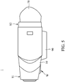
- Fig. 5 is a lateral side-view diagram of the electronic telescope 1.
- an adjusting wheel W is formed on the bottom of the main body 10, and is configured to adjust the focus of the lens module 30 to perform optical zoom. It should be noted that the adjusting wheel W is situated on the bottom of the main body 10 so that the user can easily operate it to adjust the focal length of the lens module 30.
- a receiving space 90 is also disposed on the bottom of the main body 10 configured to receive a battery.
- a non-rechargeable battery and the primary battery a rechargeable battery
- Fig. 6 is a schematic diagram of the observation room 100 of the main body 10 and the display module 50 of the electronic telescope 1.
- the observation room 100 is disposed between the objective end S1 and the eyepiece end S2 ( Fig. 2 ) and has a tapered structure.
- the tapered structure has a first end 101 and a second end 102 respectively corresponding to the objective end S1 and an eyepiece end S2, and the opening of the observation room 100 is narrower on the first end 101 than on the second end 102.
- a user can see the image on the display module 50 through the observation room 100 which provides a comfortable viewing effect for the user.
- the observation room 100 includes a first inner wall 100S1 and a second inner wall 100S2 which are facing each other, and the first and second inner walls 100S1 and 100S2 extend aslant (with respect to the central axis C of the main body 10) from the objective S1 end to the eyepiece end S2.
- the first and second inner walls 100S1 and 100S2 are formed with a plurality of scattering structures Q.
- the scattering structures Q (which may be wave-shaped) can scatter (or reflect) the oblique light scattered (or reflected) from the display module 50, to provide a good visual experience for the user.
- an electronic telescope primarily including a main body, a lens module, a display module, and a single eyepiece.
- the main body includes an objective end and an eyepiece end which is opposite the objective end.
- the lens module is disposed on the objective end.
- the display module connects to the lens module and is configured to display an image captured by the lens module.
- the single eyepiece lens with a single focus has a longitudinal structure and is disposed on the eyepiece end, wherein the eyepiece lens corresponds to the two eyes of the user. Therefore, it is convenient to use the electronic telescope since the larger single eyepiece lens with a single focus corresponds to the two eyes of the user, rather than using two independent eyepiece lenses, on which each user needs to adjust the interpupillary distance.
- the electronic telescope includes a light-emitting diode assembly so that the electronic telescope has a night vision function for use at night. Furthermore, the visual comfort and effect are enhanced via a taper-shaped observation room of the main body when watching the image on the display module.
Landscapes
- Physics & Mathematics (AREA)
- General Physics & Mathematics (AREA)
- Optics & Photonics (AREA)
- Astronomy & Astrophysics (AREA)
- Engineering & Computer Science (AREA)
- General Engineering & Computer Science (AREA)
- Telescopes (AREA)
Applications Claiming Priority (1)
| Application Number | Priority Date | Filing Date | Title |
|---|---|---|---|
| US15/723,626 US10466467B2 (en) | 2017-10-03 | 2017-10-03 | Electronic telescope |
Publications (2)
| Publication Number | Publication Date |
|---|---|
| EP3467564A2 true EP3467564A2 (fr) | 2019-04-10 |
| EP3467564A3 EP3467564A3 (fr) | 2019-06-26 |
Family
ID=63642823
Family Applications (1)
| Application Number | Title | Priority Date | Filing Date |
|---|---|---|---|
| EP18195410.8A Withdrawn EP3467564A3 (fr) | 2017-10-03 | 2018-09-19 | Télescope électronique |
Country Status (3)
| Country | Link |
|---|---|
| US (1) | US10466467B2 (fr) |
| EP (1) | EP3467564A3 (fr) |
| CN (1) | CN109597196A (fr) |
Cited By (1)
| Publication number | Priority date | Publication date | Assignee | Title |
|---|---|---|---|---|
| EP3819694A1 (fr) * | 2019-11-11 | 2021-05-12 | Changing International Company Limited | Binoculaire optique |
Families Citing this family (11)
| Publication number | Priority date | Publication date | Assignee | Title |
|---|---|---|---|---|
| USD938507S1 (en) * | 2020-04-20 | 2021-12-14 | Shenzhen Bailefu Electronic Technology Co., Ltd. | Night vision device |
| US11550139B2 (en) * | 2020-10-30 | 2023-01-10 | Changing International Company Limited | Night-vision optical device with automatic infrared-cut function |
| CN113514869B (zh) * | 2021-04-23 | 2023-12-08 | 北京大学 | 行星际能量粒子探头、探测系统及探测方法 |
| USD949221S1 (en) * | 2021-05-06 | 2022-04-19 | Dongguan Aomeijia Electronic Co., Ltd. | Night vision goggles |
| USD954123S1 (en) * | 2021-06-22 | 2022-06-07 | Shenzhen Zhuopu Digital Technology Co., Ltd. | Night vision goggles |
| USD977544S1 (en) * | 2022-06-24 | 2023-02-07 | Gaodi Digital (Qingdao) Co., Ltd. | Night vision goggle |
| USD984507S1 (en) * | 2022-09-26 | 2023-04-25 | Gaodi Digital (Qingdao) Co., Ltd. | Night vision goggle |
| USD1062822S1 (en) * | 2022-10-10 | 2025-02-18 | Shenzhen Zecre Technology Co., Ltd | Night vision goggles |
| CN119717244A (zh) * | 2023-09-28 | 2025-03-28 | 海狸文创科技(深圳)有限公司 | 一种结合手机应用的数码望远镜 |
| USD1120059S1 (en) * | 2024-04-25 | 2026-03-24 | Dingkun Wang | Night vision goggle |
| USD1107091S1 (en) * | 2024-05-07 | 2025-12-23 | Shenzhen Longzhiyuan Technology Co., Ltd. | Night-vision device |
Citations (2)
| Publication number | Priority date | Publication date | Assignee | Title |
|---|---|---|---|---|
| US20110141223A1 (en) * | 2008-06-13 | 2011-06-16 | Raytheon Company | Multiple Operating Mode Optical Instrument |
| CN204241758U (zh) * | 2014-12-12 | 2015-04-01 | 诠兴国际电子有限公司 | 具夜视功能的望远镜 |
Family Cites Families (7)
| Publication number | Priority date | Publication date | Assignee | Title |
|---|---|---|---|---|
| US3658412A (en) | 1970-10-01 | 1972-04-25 | Chrysler Corp | Wide angle biocular eyepiece |
| US3922524A (en) | 1973-09-20 | 1975-11-25 | Us Army | Modular biocular eyepiece for thermal image systems |
| GB8511978D0 (en) | 1985-05-11 | 1987-09-09 | Pilkington Perkin Elmer Ltd | Optical apparatus |
| US5903337A (en) | 1996-04-18 | 1999-05-11 | Fuji Photo Film Co., Ltd. | Film viewer |
| US7110171B2 (en) * | 2003-10-30 | 2006-09-19 | Metal Improvement Company, Llc | Relay telescope including baffle, and high power laser amplifier utilizing the same |
| US8072469B2 (en) | 2007-04-03 | 2011-12-06 | L-3 Communications Insight Technology Incorporated | Fusion night vision system with parallax correction |
| USD752670S1 (en) * | 2014-12-03 | 2016-03-29 | Changing International Company Limited | Night vision telescope |
-
2017
- 2017-10-03 US US15/723,626 patent/US10466467B2/en active Active
-
2018
- 2018-04-28 CN CN201810404042.XA patent/CN109597196A/zh active Pending
- 2018-09-19 EP EP18195410.8A patent/EP3467564A3/fr not_active Withdrawn
Patent Citations (2)
| Publication number | Priority date | Publication date | Assignee | Title |
|---|---|---|---|---|
| US20110141223A1 (en) * | 2008-06-13 | 2011-06-16 | Raytheon Company | Multiple Operating Mode Optical Instrument |
| CN204241758U (zh) * | 2014-12-12 | 2015-04-01 | 诠兴国际电子有限公司 | 具夜视功能的望远镜 |
Cited By (2)
| Publication number | Priority date | Publication date | Assignee | Title |
|---|---|---|---|---|
| EP3819694A1 (fr) * | 2019-11-11 | 2021-05-12 | Changing International Company Limited | Binoculaire optique |
| US11054642B2 (en) | 2019-11-11 | 2021-07-06 | Changing International Company Limited | Optical binoculars |
Also Published As
| Publication number | Publication date |
|---|---|
| US20190101743A1 (en) | 2019-04-04 |
| US10466467B2 (en) | 2019-11-05 |
| EP3467564A3 (fr) | 2019-06-26 |
| CN109597196A (zh) | 2019-04-09 |
Similar Documents
| Publication | Publication Date | Title |
|---|---|---|
| US10466467B2 (en) | Electronic telescope | |
| US11054642B2 (en) | Optical binoculars | |
| US11550139B2 (en) | Night-vision optical device with automatic infrared-cut function | |
| EP3420881B1 (fr) | Agencement de lentille d'endoscope pour commande d'angle de faisceau principal au niveau du capteur | |
| KR20070085217A (ko) | 내구성 디지털 저조도 관측 장치 및 그 제어 방법 | |
| US9395518B2 (en) | Imaging lens | |
| CN107229122B (zh) | 头戴式显示装置 | |
| US11143491B2 (en) | Sighting device | |
| CN104871081B (zh) | 相机模块以及具有该相机模块的相机装置 | |
| US20200249447A1 (en) | Camera module and electronic device | |
| US9894263B2 (en) | Handheld magnifier camera with variable focus distance | |
| US12130419B2 (en) | Electro-optics based optical devices | |
| WO2021059690A1 (fr) | Module optique et dispositif d'authentification | |
| TW202004245A (zh) | 微型化的攝像模組 | |
| TW201516466A (zh) | 頭戴式顯示裝置 | |
| US11357389B1 (en) | Sub-millimeter tuning focus apparatus for a medical device | |
| US10848705B1 (en) | Night-viewing device | |
| KR20190120629A (ko) | 이미지 획득 장치 | |
| CN223528122U (zh) | 一种双目镜红外热成像仪 | |
| CN114822245B (zh) | 电子设备 | |
| TWI719760B (zh) | 電子裝置 | |
| KR101026455B1 (ko) | 이중 볼록렌즈를 이용한 투시경 장치 | |
| WO2004053559A3 (fr) | Dispositif optique d'objectif de microscope | |
| US10349045B2 (en) | Three-dimensional (3D) viewing device and system thereof | |
| JP2007047526A (ja) | アタッチメント付きカメラモジュール |
Legal Events
| Date | Code | Title | Description |
|---|---|---|---|
| PUAI | Public reference made under article 153(3) epc to a published international application that has entered the european phase |
Free format text: ORIGINAL CODE: 0009012 |
|
| STAA | Information on the status of an ep patent application or granted ep patent |
Free format text: STATUS: THE APPLICATION HAS BEEN PUBLISHED |
|
| AK | Designated contracting states |
Kind code of ref document: A2 Designated state(s): AL AT BE BG CH CY CZ DE DK EE ES FI FR GB GR HR HU IE IS IT LI LT LU LV MC MK MT NL NO PL PT RO RS SE SI SK SM TR |
|
| AX | Request for extension of the european patent |
Extension state: BA ME |
|
| PUAL | Search report despatched |
Free format text: ORIGINAL CODE: 0009013 |
|
| AK | Designated contracting states |
Kind code of ref document: A3 Designated state(s): AL AT BE BG CH CY CZ DE DK EE ES FI FR GB GR HR HU IE IS IT LI LT LU LV MC MK MT NL NO PL PT RO RS SE SI SK SM TR |
|
| AX | Request for extension of the european patent |
Extension state: BA ME |
|
| RIC1 | Information provided on ipc code assigned before grant |
Ipc: G02B 23/12 20060101AFI20190517BHEP Ipc: G02B 25/00 20060101ALI20190517BHEP |
|
| STAA | Information on the status of an ep patent application or granted ep patent |
Free format text: STATUS: REQUEST FOR EXAMINATION WAS MADE |
|
| 17P | Request for examination filed |
Effective date: 20191223 |
|
| RBV | Designated contracting states (corrected) |
Designated state(s): AL AT BE BG CH CY CZ DE DK EE ES FI FR GB GR HR HU IE IS IT LI LT LU LV MC MK MT NL NO PL PT RO RS SE SI SK SM TR |
|
| STAA | Information on the status of an ep patent application or granted ep patent |
Free format text: STATUS: EXAMINATION IS IN PROGRESS |
|
| 17Q | First examination report despatched |
Effective date: 20220509 |
|
| STAA | Information on the status of an ep patent application or granted ep patent |
Free format text: STATUS: THE APPLICATION IS DEEMED TO BE WITHDRAWN |
|
| 18D | Application deemed to be withdrawn |
Effective date: 20240403 |