EP3467573A1 - Procédé de conception de lentille de correction de vision, et lentille de correction de vision - Google Patents
Procédé de conception de lentille de correction de vision, et lentille de correction de vision Download PDFInfo
- Publication number
- EP3467573A1 EP3467573A1 EP16922435.9A EP16922435A EP3467573A1 EP 3467573 A1 EP3467573 A1 EP 3467573A1 EP 16922435 A EP16922435 A EP 16922435A EP 3467573 A1 EP3467573 A1 EP 3467573A1
- Authority
- EP
- European Patent Office
- Prior art keywords
- lens
- constant
- focal depth
- edge thickness
- axis
- Prior art date
- Legal status (The legal status is an assumption and is not a legal conclusion. Google has not performed a legal analysis and makes no representation as to the accuracy of the status listed.)
- Withdrawn
Links
Images




Classifications
-
- G—PHYSICS
- G02—OPTICS
- G02C—SPECTACLES; SUNGLASSES OR GOGGLES INSOFAR AS THEY HAVE THE SAME FEATURES AS SPECTACLES; CONTACT LENSES
- G02C7/00—Optical parts
- G02C7/02—Lenses; Lens systems ; Methods of designing lenses
- G02C7/04—Contact lenses for the eyes
- G02C7/041—Contact lenses for the eyes bifocal; multifocal
-
- G—PHYSICS
- G02—OPTICS
- G02C—SPECTACLES; SUNGLASSES OR GOGGLES INSOFAR AS THEY HAVE THE SAME FEATURES AS SPECTACLES; CONTACT LENSES
- G02C7/00—Optical parts
- G02C7/02—Lenses; Lens systems ; Methods of designing lenses
-
- G—PHYSICS
- G02—OPTICS
- G02C—SPECTACLES; SUNGLASSES OR GOGGLES INSOFAR AS THEY HAVE THE SAME FEATURES AS SPECTACLES; CONTACT LENSES
- G02C7/00—Optical parts
- G02C7/02—Lenses; Lens systems ; Methods of designing lenses
- G02C7/024—Methods of designing ophthalmic lenses
-
- G—PHYSICS
- G02—OPTICS
- G02C—SPECTACLES; SUNGLASSES OR GOGGLES INSOFAR AS THEY HAVE THE SAME FEATURES AS SPECTACLES; CONTACT LENSES
- G02C7/00—Optical parts
- G02C7/02—Lenses; Lens systems ; Methods of designing lenses
- G02C7/06—Lenses; Lens systems ; Methods of designing lenses bifocal; multifocal ; progressive
Definitions
- the present invention relates to a corrective lens such as an eyeglass lens or contact lens and a design method for the corrective lens and, more particularly, to a corrective lens having a focal depth extension effect and a design method for the corrective lens.
- Patent Literature 1 discloses an optical plate that can increase the optical depth, which is the optical plate of the second optical system disposed in front of the first optical system serving as an imaging optical system for incident light waves. It is described that this optical plate increases in thickness almost in proportion to a third-order power function of the distance from a base point in the optical plate.
- Patent Literature 1 JP No. 2009-282391 A (see Claims 1 and 2)
- the present invention solves the above problem and has its object to provide a design method for a corrective lens that can improve contrast sensitivity in a dark place and a corrective lens.
- a design method for a corrective lens according to the present invention is characterized in that when an axis in an anteroposterior direction passing through the geometric center of a lens is defined as the z-axis and a direction extending to the rear side of the lens is defined as the positive direction of the z-axis, a focal depth extension component represented by Ar 3 (where r is the distance from the z-axis and A is a constant) is added to the z-coordinate value of a refractive surface determined based on a prescription power to increase the focal depth.
- a corrective lens prepared by this preparation method increases in focal depth, which decreases (shallows) in a dark place, to facilitate focusing on a target object located in front of or behind the original focal point. This makes it possible to improve the contrast sensitivity in a dark place.
- an edge thickness reduction component for a reduction in edge thickness of the lens is preferably added to the z-coordinate value. This is because adding the edge thickness reduction component will reduce the edge thickness that is increased by the addition of a focal depth extension component.
- the edge thickness reduction component is preferably represented by Dr 10 (where D is a negative constant when constant A is positive, and is a positive constant when constant A is negative). This is because such setting increases the influence on the edge portion of the lens and can reduce the edge thickness.
- the constant A is preferably set such that the absolute value of the constant A falls within a range of 1.73 ⁇ 10 -6 to 1.96 ⁇ 10 -5 . This is because when the absolute value of constant A for an eyeglass lens having a normal size falls within such a range, an appropriate focal depth extension effect can be obtained, and the occurrence of astigmatism can be suppressed.
- the constant A and the constant D are preferably set such that the absolute value of the constant A falls within a range of 1.73 ⁇ 10 -6 to 1.96 ⁇ 10 -5 , the absolute value of the constant D falls within a range of 1.65 ⁇ 10 -17 to 1.88 ⁇ 10 -16 , and the absolute value of the constant D increases with an increase in the absolute value of the constant A.
- This is because setting constant A and constant D for an eyeglass lens having a normal size in this manner can provide an appropriate focal depth extension effect and suppress the occurrence of astigmatism. In addition, this can make the edge thickness equal to that of the lens before the addition of a focal depth extension component.
- a corrective lens according to the present invention is characterized in that when an axis in an anteroposterior direction passing through the geometric center of a lens is defined as the z-axis and a direction extending to the rear side of the lens is defined as the positive direction of the z-axis, a focal depth extension component represented by Ar 3 (where r is the distance from the z-axis and A is a constant) is added to the z-coordinate value of a refractive surface determined based on a prescription power to increase the focal depth.
- This lens increases in focal depth, which decreases (shallows) in a dark place, to facilitate focusing on a target object located in front of or behind the original focal point. This makes it possible to improve the contrast sensitivity in a dark place.
- an edge thickness reduction component for a reduction in edge thickness of the lens is preferably added to the z-coordinate value. This is because adding the edge thickness reduction component will reduce the edge thickness that is increased by the addition of a focal depth extension component.
- the edge thickness reduction component is preferably represented by Dr 10 (where D is a negative constant when constant A is positive, and is a positive constant when constant A is negative). This is because such setting increases the influence on the edge portion of the lens and can reduce the edge thickness.
- the absolute value of the constant A preferably falls within a range of 1.73 ⁇ 10 -6 to 1.96 ⁇ 10 -5 . This is because when the absolute value of constant A for an eyeglass lens having a normal size falls within such a range, an appropriate focal depth extension effect can be obtained, and the occurrence of astigmatism can be suppressed.
- a lens 1 according to the first embodiment is a corrective lens for correcting the vision of the wearer, and more specifically an eyeglass lens used for eyeglasses.
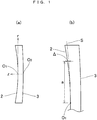
- the lens 1 has, as a rear surface 2, a concave surface defined by equation (i), and, as a front surface 3, a convex surface defined by equation (ii).
- an axis in an anteroposterior direction passing through the geometric center of the lens 1 is defined as the z-axis and a direction extending to the rear side of the lens 1 is defined as the positive direction of the z-axis.
- r is the distance from the z-axis.
- r (x 2 + y 2 ) 1/2 .
- R 1 and R 2 are curvature radii at the vertices of the surfaces, K is 1, and A is a positive constant. Accordingly, the front surface 3 and the rear surface 2 of the lens 1 are respectively a spherical surface and an aspherical surface. Note that R 1 and R 2 are determined by a prescription power (more specifically, S power, C power, and astigmatic axis AX).
- the lens 1 is a distance lens for a myopic person, and hence R 1 ⁇ R 2 .
- a third-order term Ar 3 of r is added to the z-coordinate value of a refractive surface defined by equation (iii) given below based on a prescription power.
- z r 2 / R 1 + R 1 2 ⁇ Kr 2 1 / 2
- Ar 3 is a focal depth extension component added for focal depth extension.
- the focal depth can be increased by causing light to pass through an optical plate whose thickness is changed in proportion to a third-order power function of the distance r from the base point.
- the lens 1 is an application of this technique.
- the rear surface 2 of this lens is formed by adding a portion (focal depth extension component) whose thickness changes in proportion to a third-order power function of the distance r from the z-axis (that is, the distance from the base point O 1 as an intersection point between the z-axis and the rear surface 2 shown in Fig. 1 ) to the refractive surface determined based on a prescription power (in this embodiment, a spherical surface with the curvature radius R 1 , which will also be referred to as the original spherical surface hereinafter and is denoted by reference symbol S in (b) in Fig. 1 ).
- a prescription power in this embodiment, a spherical surface with the curvature radius R 1 , which will also be referred to as the original spherical surface hereinafter and is denoted by reference symbol S in (b) in Fig. 1 ).
- the rear surface 2 can be said to be a combination of the spherical surface with the curvature radius R 1 and the aspherical surface represented by Ar 3 .
- the rear surface 2 is formed by combining a power component for implementing a prescription power and a focal depth extension component (aspherical component) for focal depth extension.
- Constant A is selected from a range of 1.73 ⁇ 10 -6 to 1.96 ⁇ 10 -5 for the following reason.
- constant A for an eyeglass lens having a normal size falls within this range, an appropriate focal depth extension effect can be obtained, and the occurrence of astigmatism can be suppressed. That is, with an increase in constant A, the focal depth extension effect increases, and the occurrence of astigmatism increases.
- the above range is determined in consideration of the balance between them.
- the refractive surface of the front surface 3 and the refractive surface of the rear surface 2 of the lens 1 are determined based on a prescription power. This determination method is well known, and hence a detailed description of the method will be omitted.
- a focal depth extension component represented by Ar 3 (where r is the distance from the z-axis and A is a constant) is then added to the z-coordinate value of the determined refractive surface of the front surface 3 or the rear surface 2.
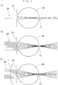
- FIG. 3 (a) is schematic view of a focused state of light beams 22 by an ordinary lens 10 whose refractive surfaces of the front and rear surfaces are determined based on a prescription power.
- the light beams 22 incident on the lens 10 and parallel to the optical axis are focused to a focal position P 3 in a convergent manner, and hence the signal intensity is high at the focal position P 3 to provide a clear view of a target object.
- the object at a position P 4 slightly shifted from the focus, the object rapidly blurs and fades. That is, the focal depth (in other words, the depth of field) is shallow.
- the set of points shown in the lower part of (a) in Fig. 3 schematically shows how the light beams 22 converge at each of the positions P 1 , P 2 , P 3 , P 4 , and P 5 .
- (b) is a schematic view of a focused state of light beams 22 by the lens 1.
- the light beams 22 incident on the lens 1 and parallel to the optical axis converge while diverging within a certain range including the focal position P 3 , resulting in a deep focal depth. Accordingly, although the target object still slightly blurs at the focal position P 3 , the target object can be identified even at a position slightly shifted from the focus like the position P 4 because the signal intensity at a central part is high to a certain degree. Note that when constant A is a positive number, the focal depth is increased to the rear side (depth side) of the original focal position P 3 .
- Fig. 4 shows the states of an eyeball 20 including an iris 21. Note that reference symbols F 1 , F 2 , and F 3 in Fig. 4 denote focal depths (lengths).
- FIG. 4 shows the state of the eyeball 20 in a bright place with high illuminance, for example, in the daytime.
- the iris 21 closes to narrow the incident light beams 22.
- the range in which light is focused extends, and hence the focal depth F 1 deepens (increases). Accordingly, focusing is achieved over a relatively long distance.
- FIG. 4 shows the state of the eyeball 20 in a dark place, in which the iris 21 opens to thicken the incident light beams 22.
- the range in which light is focused shortens, and hence the focal depth F 2 shallows (decreases). Accordingly, the distance over which focusing is achieved shortens.
- FIG. 4 shows the state of the eyeball 20 when the lens 1 is used in a dark place.
- the iris 21 opens to thicken the incident light beams 22.
- the focal depth F 3 is large, focusing is achieved over a relatively long distance. Accordingly, the lens 1 facilitates identifying a target object in a dark place, in particular.
- Figs. 5 to 8 show the experimental results obtained by shooting indices in a case in which an ordinary single-focus lens (without power) to which no focal depth extension component is added is attached to the front side of the lens of a camera and in a case in which a focal depth extension lens obtained by adding a focal depth extension component in the manner described above to a single-focus lens with the same design as that of the ordinary single-focus lens is attached to the front side of the lens of the camera and comparing the resultant depths of field with each other.
- a plurality of indices were arranged at equal intervals (the intervals in the anteroposterior direction were 15 cm in Figs. 5 and 6 , and 10 cm in Figs. 7 and 8 ) obliquely with respect to the camera.
- Figs. 5 and 6 respectively show the photographs obtained by shooting with the single-focus lens and the focal depth extension lens in a bright place, with focal length: 135 mm, F-number: 4.5, shutter speed: 1/25, ISO: 400, distance from camera to nearest index: about 200 cm, illuminance near camera: 80 Ix, and illuminance close to the nearest index: 90 Ix.
- Figs. 7 and 8 respectively show the photographs obtained by shooting with the single-focus lens and the focal depth extension lens in a dark place, with focal length: 135 mm, F-number: 8.0, shutter speed: 1/10, ISO: 400, distance from camera to nearest index: about 100 cm, illuminance near camera: 48 Ix, and illuminance close to the nearest index: 55 Ix.
- R and L in Table 3 respectively represent a right eye and a left eye, and each lens has a refractive index of 1.60.
- the contrast sensitivities were measured by using vision contrast tester 6500 available from Vitech Corporation.
- Table 4 shows the measurement results.
- Vison contrast tester 6500 available from Vitech Corporation is designed to measure a contrast sensitivity depending on up to which index of a plurality of indices, arranged for each of indices A to E, it can identify.
- Table 4 shows up to which index each subject was able to identify for each of indices A to E. Note that in Table 4, lens A indicates an ordinary single-focus lens, and lens B indicates the lens 1.
- measurements were conducted on the right eye, the left eye, and both eyes in bright and dark places.
- Table 4 includes illuminances in the respective measurement places. The distance from each subject to each index is 3.00 m.
- Contrast sensitivities are converted according to a predetermined conversion table such that, for example, measurement result "6" on index B is converted into contrast sensitivity "85,” and measurement result "7” is converted into contrast sensitivity "170.”
- the ratios of the contrast sensitivities obtained with the lenses 1 to the contrast sensitivities obtained with the ordinary single-focus lenses concerning the right eye, the left eye, and both eyes of each subject in each of the bright and dark places, i.e., (contrast sensitivities with lenses 1)/(contrast sensitivities with ordinary single-focus lenses), are obtained for each of indices A to E, based on the contrast sensitivities obtained from the measurement results in Table 4.
- Table 5 shows the averages of the obtained ratios throughout the respective indices.
- Table 5 indicates that when, for example, subject A sees with both eyes in a bright place, the contrast sensitivity obtained with the lenses 1 is 100% with respect to the contrast sensitivity obtained with the ordinary single-focus lenses. That is, the contrast sensitivity remains the same with the use of either the lenses 1 or the ordinary single-focus lenses.
- the contrast sensitivity obtained with the lenses 1 is 220% with respect to the contrast sensitivity obtained with the ordinary single-focus lenses. That is, the contrast sensitivity obtained with the use of the lenses 1 is increased more than twice that obtained with the use of the ordinary single-focus lenses.
- in the dark place luminance: 50 Ix or less
- increases in contrast sensitivity were observed in 12 eyes out of 16 eyes.
- the lens 1 improves the contrast sensitivity in a dark place where a decrease in contrast is observed, for example, in the evening or at night, and exhibits a high contrast sensitivity improving effect in a dark place especially for middle-aged and elderly persons whose contrast sensitivities rapidly deteriorate.
- constant A from a range of 1.73 ⁇ 10 -6 to 1.96 ⁇ 10 -5 makes it possible to obtain an appropriate focal depth extension effect and suppress the occurrence of astigmatism. That is, this increases the focal depth while suppressing peripheral distortion, and hence assists the accommodation of the eyes, thereby allowing the eyes to experience a comfortable feeling and hardly experience fatigue.
- a lens according to the second embodiment is also an eyeglass lens.
- a front surface 3 is a convex surface defined by equation (ii) given above, but a rear surface 2 is obtained by adding an edge thickness reduction component Dr 10 (where D is a negative constant) for reducing the edge thickness of the lens to the z-coordinate value of the rear surface 2. That is, the rear surface 2 of the lens according to the second embodiment is a concave surface defined by equation (iv) given below.
- the edge thickness reduction component Dr 10 is added to the lens according to the second embodiment in order to reduce the inconvenience of a thick edge thickness of the lens caused by the addition of the focal depth extension component Ar 3 (where A is a positive constant) in terms of appearance and weight.
- the exponent of r in an edge thickness reduction component is set to as large as 10 to increase the influence on the edge portion of the lens so as to reduce the edge thickness. Note that because r is small in a central portion of the rear surface 2 which is used to see an object, the edge thickness reduction component Dr 10 is small, and no negative influence is exerted on the focal depth extension effect.
- constant A is preferably selected from a range of 1.73 ⁇ 10 -6 to 1.96 ⁇ 10 -5 .
- constant D is preferably selected from a range of -1.88 ⁇ 10 -16 to -1.65 ⁇ 10 -17 , and is also preferably selected such that the absolute value of constant D increases with an increase in constant A. This is because selecting constant D in this manner will make the edge thickness of the lens equal to that of an ordinary single-focus lens.
- adding the edge thickness reduction component Dr 10 makes the edge thickness of the lens according to the second embodiment equal to that of the ordinary single-focus lens.
- the lens according to the second embodiment improves the contrast sensitivity in a dark place, especially the contrast sensitivity of middle-aged and elderly persons in a dark place, and can make the edge thickness of the lens equal to that of an ordinary lens.
- the first and second embodiments are each a single-focus lens (distance lens) for a myopic person.
- the third embodiment is a single-focus lens (near lens) for a hyperopic person.
- the third embodiment will be described below.
- the same reference numerals denote constituent elements common to those of the first embodiment, and a description of them will be omitted as appropriate.
- the lens according to the third embodiment also has a rear surface 2 defined by equation (i) given above and a front surface 3 defined by equation (ii) given above, and a focal depth extension component Ar 3 is added to the concave surface (rear surface 2) of the lens, with constant A being a negative number and selected from a range of -1.96 ⁇ 10 -5 to -1.73 ⁇ 10 -6 .
- constant A being a negative number and selected from a range of -1.96 ⁇ 10 -5 to -1.73 ⁇ 10 -6 .
- R 1 > R 2 .
- Fig. 9 shows a schematic view (a) of the overall lens according to the third embodiment and an enlarged schematic view (b) of an upper half of the lens.
- the lens according to the third embodiment is configured such that the thickness of an original spherical surface S indicated by the two-dot chain line is reduced, and the amount of reduction in the thickness increases toward the edge of the lens.
- Table 8 shows an example of lenses according to the third embodiment which respectively have S powers of +1.00D, +2.00D, and +3.00D. Constant A was set to - 7.68 ⁇ 10 -6 .
- the lens according to the third embodiment is configured such that the height from the original spherical surface S decreases in proportion to a third-order power function of a distance r from a base point O 1 . Accordingly, the focal point is shifted forward toward the edge of the lens. This increases the extension depth and improves the contrast sensitivity in a dark place. In addition, there is no need to add any edge thickness reduction component.
- the fourth embodiment is a single-focus lens (near lens) for a hyperopic person, and differs from the third embodiment in that constant A is a positive number.
- the fourth embodiment will be described below.
- the same reference numerals denote constituent elements common to those of the first embodiment, and a description of them will be omitted as appropriate.
- the lens according to the fourth embodiment also has a rear surface 2 defined by equation (i) given above and a front surface 3 defined by equation (ii) given above, and a focal depth extension component Ar 3 is added to the concave surface (rear surface 2) of the lens, with constant A being a positive number and selected from a range of 1.73 ⁇ 10 -6 to 1.69 ⁇ 10 -5 .
- constant A is a positive number and selected from a range of 1.73 ⁇ 10 -6 to 1.69 ⁇ 10 -5 .
- R 1 > R 2 .
- Table 9 shows an example of lenses according to the third embodiment which respectively have S powers of +1.00D, +2.00D, and +3.00D. Constant A was set to 7.68 ⁇ 10 -6 .
- constant A is selected from a range of 1.73 ⁇ 10 -6 to 1.96 ⁇ 10 -5
- constant D is preferably selected from a range of -1.88 ⁇ 10 -16 to -1.65 ⁇ 10 -17 , and is also preferably selected such that the absolute value of constant D increases with an increase in constant A.
- the lens according to the fourth embodiment is configured such that the height from an original spherical surface S increases in proportion to a third-order power function of a distance r from a base point O 1 . Accordingly, the focal point is shifted backward with a reduction in distance to the edge of the lens. This increases the extension depth and improves contrast in a dark place.
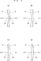
- the focal depth extension component may be added to the rear surface 2 in one case, or may be added to the front surface 3 in another case.
- constant A is set to a positive number or a negative number.
- Fig. 10 shows these four cases. In Fig.
- each two-dot chain line indicates a surface before the addition of the focal depth extension component.
- the absolute value of constant A preferably falls within a range of 1.73 ⁇ 10 -6 to 1.96 ⁇ 10 -5 . This is because it is obvious in terms of calculation that when constant A falls within this range, an appropriate focal depth extension can be obtained, and the occurrence of astigmatism can be suppressed.
- an edge thickness reduction component may be added to the lens because the edge thickness increases.
- no edge thickness reduction component needs to be added because the edge thickness decreases. Assume that an edge thickness reduction component is added.
- constant A is a positive number as indicated by (a)
- constant D is set to a negative number
- constant D is set to a positive number.
- the absolute value of constant D is preferably set within a range of 1.65 ⁇ 10 -17 to 1.88 ⁇ 10 -16 , and the absolute value of constant D is preferably set so as to increase with an increase in the absolute value of constant A. This is because it is obvious in terms of calculation that determining constant A and constant D for an eyeglass lens having a normal size in this manner can provide an appropriate focal depth extension effect and suppress the occurrence of astigmatism, and in addition, the edge thickness can be set to be equal to that of the lens before the addition of a focal depth extension component.
Landscapes
- Health & Medical Sciences (AREA)
- Ophthalmology & Optometry (AREA)
- Physics & Mathematics (AREA)
- General Health & Medical Sciences (AREA)
- General Physics & Mathematics (AREA)
- Optics & Photonics (AREA)
- Eyeglasses (AREA)
Applications Claiming Priority (1)
| Application Number | Priority Date | Filing Date | Title |
|---|---|---|---|
| PCT/JP2016/084962 WO2018096647A1 (fr) | 2016-11-25 | 2016-11-25 | Procédé de conception de lentille de correction de vision, et lentille de correction de vision |
Publications (3)
| Publication Number | Publication Date |
|---|---|
| EP3467573A1 true EP3467573A1 (fr) | 2019-04-10 |
| EP3467573A9 EP3467573A9 (fr) | 2019-07-10 |
| EP3467573A4 EP3467573A4 (fr) | 2020-01-22 |
Family
ID=62194968
Family Applications (1)
| Application Number | Title | Priority Date | Filing Date |
|---|---|---|---|
| EP16922435.9A Withdrawn EP3467573A4 (fr) | 2016-11-25 | 2016-11-25 | Procédé de conception de lentille de correction de vision, et lentille de correction de vision |
Country Status (5)
| Country | Link |
|---|---|
| US (1) | US11131868B2 (fr) |
| EP (1) | EP3467573A4 (fr) |
| JP (1) | JP7055318B2 (fr) |
| CN (1) | CN109196407A (fr) |
| WO (1) | WO2018096647A1 (fr) |
Cited By (2)
| Publication number | Priority date | Publication date | Assignee | Title |
|---|---|---|---|---|
| US11300805B2 (en) | 2018-07-03 | 2022-04-12 | National University Corporation Tokyo University Of Agriculture And Technology | Stereoscopic eyeglasses, method for designing eyeglass lens to be used for the stereoscopic eyeglasses, and method for observing stereoscopic image |
| US11740459B2 (en) | 2018-10-15 | 2023-08-29 | National University Corporation Tokyo University Of Agriculture And Technology | Head-mounted display and method for designing wide-focus lens to be used for the head-mounted display |
Families Citing this family (2)
| Publication number | Priority date | Publication date | Assignee | Title |
|---|---|---|---|---|
| WO2021149628A1 (fr) * | 2020-01-23 | 2021-07-29 | 国立大学法人東京農工大学 | Visiocasque et lentille de formation d'image virtuelle l'utilisant |
| JP7405371B2 (ja) * | 2020-08-24 | 2023-12-26 | 伊藤光学工業株式会社 | ゲーミングレンズの設計方法 |
Family Cites Families (21)
| Publication number | Priority date | Publication date | Assignee | Title |
|---|---|---|---|---|
| US4181409A (en) * | 1978-10-16 | 1980-01-01 | American Optical Corporation | Aspheric lens series |
| JPS6450012A (en) * | 1987-08-21 | 1989-02-27 | Asahi Glass Co Ltd | Spectacle lens with small aberration |
| JP3334131B2 (ja) * | 1991-10-09 | 2002-10-15 | セイコーエプソン株式会社 | 眼鏡レンズの製造方法 |
| US5767939A (en) * | 1991-10-09 | 1998-06-16 | Seiko Epson Corporation | Eyeglass lens |
| CN1412604A (zh) * | 2002-11-07 | 2003-04-23 | 苏州大学 | 非球面眼镜片 |
| JP2005242346A (ja) * | 2004-01-28 | 2005-09-08 | Pentax Corp | 眼鏡レンズの設計方法および眼鏡レンズ |
| CN100445806C (zh) * | 2004-06-17 | 2008-12-24 | 鸿富锦精密工业(深圳)有限公司 | 眼镜片 |
| US20060066808A1 (en) * | 2004-09-27 | 2006-03-30 | Blum Ronald D | Ophthalmic lenses incorporating a diffractive element |
| CN100445805C (zh) * | 2004-11-27 | 2008-12-24 | 鸿富锦精密工业(深圳)有限公司 | 远视眼镜片 |
| US8079704B2 (en) * | 2006-12-27 | 2011-12-20 | Hoya Corporation | Multifocal ophthalmic lens |
| US8740978B2 (en) * | 2007-08-27 | 2014-06-03 | Amo Regional Holdings | Intraocular lens having extended depth of focus |
| DE102007062929A1 (de) * | 2007-12-28 | 2009-07-02 | Rodenstock Gmbh | Verfahren zur Berechnung und Optimierung eines Brillenglaspaares unter Berücksichtigung binokularer Eigenschaften |
| JP4335957B1 (ja) * | 2008-05-23 | 2009-09-30 | 規 有賀 | 大型光学板 |
| EP2149812B1 (fr) * | 2008-07-31 | 2021-08-25 | Hoya Corporation | Lentille d'ajout progressif, procédé pour la préparation des données de forme, procédé de fabrication de la lentille, et appareil et produit de programme informatique pour préparer de telles données de forme |
| EP2407815B1 (fr) * | 2009-03-12 | 2018-08-15 | Hoya Corporation | Procédé de compilation de données de forme d'une lentille de lunettes, dispositif de compilation de données de forme d'une lentille de lunettes et lentille de lunettes |
| CN104094165B (zh) * | 2011-06-15 | 2017-08-25 | 文森尔林技术公司 | 治疗近视加深的方法 |
| DE102011114752A1 (de) | 2011-09-29 | 2013-04-04 | Carl Zeiss Ag | Linse mit einem erweiterten Fokusbereich |
| CA2877234A1 (fr) * | 2013-03-07 | 2014-09-12 | Amo Groningen B.V. | Lentille comportant une profondeur de foyer etendue et procede associe a celle-ci |
| JP5882437B1 (ja) * | 2014-11-07 | 2016-03-09 | 伊藤光学工業株式会社 | 眼鏡レンズ |
| DE102014223341B4 (de) * | 2014-11-14 | 2021-09-23 | Carl Zeiss Vision International Gmbh | Optische Sehhilfe, Verwendung einer optischen Sehhilfe, Verfahren, Computerprogramm und System für das Ermitteln einer gesuchten Parametrisierung der dioptrischen Wirkung einer optischen Sehhilfe |
| JP6374345B2 (ja) | 2015-04-20 | 2018-08-15 | 伊藤光学工業株式会社 | 視力矯正用レンズの設計方法及び視力矯正用レンズ |
-
2016
- 2016-11-25 EP EP16922435.9A patent/EP3467573A4/fr not_active Withdrawn
- 2016-11-25 CN CN201680086335.7A patent/CN109196407A/zh active Pending
- 2016-11-25 WO PCT/JP2016/084962 patent/WO2018096647A1/fr not_active Ceased
- 2016-11-25 US US16/305,200 patent/US11131868B2/en active Active
-
2017
- 2017-04-11 JP JP2017078475A patent/JP7055318B2/ja active Active
Cited By (2)
| Publication number | Priority date | Publication date | Assignee | Title |
|---|---|---|---|---|
| US11300805B2 (en) | 2018-07-03 | 2022-04-12 | National University Corporation Tokyo University Of Agriculture And Technology | Stereoscopic eyeglasses, method for designing eyeglass lens to be used for the stereoscopic eyeglasses, and method for observing stereoscopic image |
| US11740459B2 (en) | 2018-10-15 | 2023-08-29 | National University Corporation Tokyo University Of Agriculture And Technology | Head-mounted display and method for designing wide-focus lens to be used for the head-mounted display |
Also Published As
| Publication number | Publication date |
|---|---|
| EP3467573A9 (fr) | 2019-07-10 |
| US20200319478A1 (en) | 2020-10-08 |
| US11131868B2 (en) | 2021-09-28 |
| EP3467573A4 (fr) | 2020-01-22 |
| WO2018096647A1 (fr) | 2018-05-31 |
| JP2018084788A (ja) | 2018-05-31 |
| CN109196407A (zh) | 2019-01-11 |
| JP7055318B2 (ja) | 2022-04-18 |
Similar Documents
| Publication | Publication Date | Title |
|---|---|---|
| EP1882973B1 (fr) | Procédé de conception pour verre de lunettes, verre de lunettes, et lunettes | |
| US7159981B2 (en) | Progressive refractive power lens | |
| US8540366B2 (en) | Manufacturing of progressive spectacle lens customized based on blur perception | |
| US7070274B2 (en) | Spectacle lens | |
| KR102042554B1 (ko) | 안경 렌즈 결정 방법 | |
| KR102890215B1 (ko) | 착용자의 눈의 비정상적 굴절을 교정하도록 구성되는 안과용 렌즈를 결정하기 위한 방법 | |
| EP3362842B1 (fr) | Procédé permettant de fabriquer une lentille à addition progressive ophtalmique et pour un porteur emmétrope et presbyte | |
| EP3467573A1 (fr) | Procédé de conception de lentille de correction de vision, et lentille de correction de vision | |
| EP1895351A1 (fr) | Procédé de conception de verres de lunettes | |
| KR101309003B1 (ko) | 안과용 렌즈 | |
| US12228803B2 (en) | Computer implemented method of determining a base curve for a spectacle lens and method of manufacturing a spectacle lens | |
| US9429770B2 (en) | Progressive addition lens | |
| JP6803615B2 (ja) | 眼鏡用レンズの設計方法 | |
| JP6374345B2 (ja) | 視力矯正用レンズの設計方法及び視力矯正用レンズ | |
| KR20170128228A (ko) | 착용자에 맞게 조정된 안과용 렌즈의 광학 기능을 결정하기 위한 방법 | |
| EP3547013A1 (fr) | Procédé pour déterminer une lentille ophtalmique à vision unique | |
| US20040109134A1 (en) | Progressive power lens | |
| EP3128361B1 (fr) | Verre à foyer progressif, son procédé de conception et son procédé de fabrication et système de fabrication d'un verre à foyer progressif | |
| US20130148078A1 (en) | Progressive multifocal ophthalmic lens | |
| JP6059483B2 (ja) | 眼鏡レンズの設計方法および眼鏡レンズの製造方法 | |
| EP3374823B1 (fr) | Lentilles avec une meilleure gestion de la distorsion | |
| EP3548961B1 (fr) | Procédé destiné à fournir une sélection graphique de lentilles ophtalmiques en vente libre |
Legal Events
| Date | Code | Title | Description |
|---|---|---|---|
| STAA | Information on the status of an ep patent application or granted ep patent |
Free format text: STATUS: THE INTERNATIONAL PUBLICATION HAS BEEN MADE |
|
| PUAI | Public reference made under article 153(3) epc to a published international application that has entered the european phase |
Free format text: ORIGINAL CODE: 0009012 |
|
| STAA | Information on the status of an ep patent application or granted ep patent |
Free format text: STATUS: REQUEST FOR EXAMINATION WAS MADE |
|
| 17P | Request for examination filed |
Effective date: 20181205 |
|
| AK | Designated contracting states |
Kind code of ref document: A1 Designated state(s): AL AT BE BG CH CY CZ DE DK EE ES FI FR GB GR HR HU IE IS IT LI LT LU LV MC MK MT NL NO PL PT RO RS SE SI SK SM TR |
|
| AX | Request for extension of the european patent |
Extension state: BA ME |
|
| A4 | Supplementary search report drawn up and despatched |
Effective date: 20191219 |
|
| RIC1 | Information provided on ipc code assigned before grant |
Ipc: G02C 7/02 20060101AFI20191213BHEP Ipc: G02C 13/00 20060101ALI20191213BHEP |
|
| DAV | Request for validation of the european patent (deleted) | ||
| DAX | Request for extension of the european patent (deleted) | ||
| STAA | Information on the status of an ep patent application or granted ep patent |
Free format text: STATUS: EXAMINATION IS IN PROGRESS |
|
| 17Q | First examination report despatched |
Effective date: 20221007 |
|
| STAA | Information on the status of an ep patent application or granted ep patent |
Free format text: STATUS: THE APPLICATION IS DEEMED TO BE WITHDRAWN |
|
| 18D | Application deemed to be withdrawn |
Effective date: 20250603 |