EP3467609B1 - Flugsteuerungsverfahren und -vorrichtung für unbemanntes luftfahrzeug und fernsteuerung - Google Patents
Flugsteuerungsverfahren und -vorrichtung für unbemanntes luftfahrzeug und fernsteuerung Download PDFInfo
- Publication number
- EP3467609B1 EP3467609B1 EP17802227.3A EP17802227A EP3467609B1 EP 3467609 B1 EP3467609 B1 EP 3467609B1 EP 17802227 A EP17802227 A EP 17802227A EP 3467609 B1 EP3467609 B1 EP 3467609B1
- Authority
- EP
- European Patent Office
- Prior art keywords
- locating
- flight
- positions
- remote controller
- target positions
- Prior art date
- Legal status (The legal status is an assumption and is not a legal conclusion. Google has not performed a legal analysis and makes no representation as to the accuracy of the status listed.)
- Active
Links
Images




Classifications
-
- G—PHYSICS
- G05—CONTROLLING; REGULATING
- G05D—SYSTEMS FOR CONTROLLING OR REGULATING NON-ELECTRIC VARIABLES
- G05D1/00—Control of position, course, altitude or attitude of land, water, air or space vehicles, e.g. using automatic pilots
- G05D1/0011—Control of position, course, altitude or attitude of land, water, air or space vehicles, e.g. using automatic pilots associated with a remote control arrangement
- G05D1/0044—Control of position, course, altitude or attitude of land, water, air or space vehicles, e.g. using automatic pilots associated with a remote control arrangement by providing the operator with a computer generated representation of the environment of the vehicle, e.g. virtual reality, maps
-
- G—PHYSICS
- G05—CONTROLLING; REGULATING
- G05D—SYSTEMS FOR CONTROLLING OR REGULATING NON-ELECTRIC VARIABLES
- G05D1/00—Control of position, course, altitude or attitude of land, water, air or space vehicles, e.g. using automatic pilots
- G05D1/20—Control system inputs
- G05D1/22—Command input arrangements
- G05D1/221—Remote-control arrangements
- G05D1/222—Remote-control arrangements operated by humans
- G05D1/223—Command input arrangements on the remote controller, e.g. joysticks or touch screens
-
- G—PHYSICS
- G05—CONTROLLING; REGULATING
- G05D—SYSTEMS FOR CONTROLLING OR REGULATING NON-ELECTRIC VARIABLES
- G05D1/00—Control of position, course, altitude or attitude of land, water, air or space vehicles, e.g. using automatic pilots
- G05D1/10—Simultaneous control of position or course in three dimensions
- G05D1/101—Simultaneous control of position or course in three dimensions specially adapted for aircraft
-
- B—PERFORMING OPERATIONS; TRANSPORTING
- B64—AIRCRAFT; AVIATION; COSMONAUTICS
- B64C—AEROPLANES; HELICOPTERS
- B64C39/00—Aircraft not otherwise provided for
- B64C39/02—Aircraft not otherwise provided for characterised by special use
- B64C39/024—Aircraft not otherwise provided for characterised by special use of the remote controlled vehicle type, i.e. RPV
-
- G—PHYSICS
- G05—CONTROLLING; REGULATING
- G05D—SYSTEMS FOR CONTROLLING OR REGULATING NON-ELECTRIC VARIABLES
- G05D1/00—Control of position, course, altitude or attitude of land, water, air or space vehicles, e.g. using automatic pilots
- G05D1/0011—Control of position, course, altitude or attitude of land, water, air or space vehicles, e.g. using automatic pilots associated with a remote control arrangement
- G05D1/0033—Control of position, course, altitude or attitude of land, water, air or space vehicles, e.g. using automatic pilots associated with a remote control arrangement by having the operator tracking the vehicle either by direct line of sight or via one or more cameras located remotely from the vehicle
-
- G—PHYSICS
- G05—CONTROLLING; REGULATING
- G05D—SYSTEMS FOR CONTROLLING OR REGULATING NON-ELECTRIC VARIABLES
- G05D1/00—Control of position, course, altitude or attitude of land, water, air or space vehicles, e.g. using automatic pilots
- G05D1/02—Control of position or course in two dimensions
- G05D1/0202—Control of position or course in two dimensions specially adapted to aircraft
-
- G—PHYSICS
- G05—CONTROLLING; REGULATING
- G05D—SYSTEMS FOR CONTROLLING OR REGULATING NON-ELECTRIC VARIABLES
- G05D1/00—Control of position, course, altitude or attitude of land, water, air or space vehicles, e.g. using automatic pilots
- G05D1/10—Simultaneous control of position or course in three dimensions
-
- G—PHYSICS
- G05—CONTROLLING; REGULATING
- G05D—SYSTEMS FOR CONTROLLING OR REGULATING NON-ELECTRIC VARIABLES
- G05D1/00—Control of position, course, altitude or attitude of land, water, air or space vehicles, e.g. using automatic pilots
- G05D1/20—Control system inputs
- G05D1/24—Arrangements for determining position or orientation
- G05D1/246—Arrangements for determining position or orientation using environment maps, e.g. simultaneous localisation and mapping [SLAM]
-
- G—PHYSICS
- G05—CONTROLLING; REGULATING
- G05D—SYSTEMS FOR CONTROLLING OR REGULATING NON-ELECTRIC VARIABLES
- G05D1/00—Control of position, course, altitude or attitude of land, water, air or space vehicles, e.g. using automatic pilots
- G05D1/40—Control within particular dimensions
- G05D1/46—Control of position or course in three dimensions [3D]
-
- G—PHYSICS
- G05—CONTROLLING; REGULATING
- G05D—SYSTEMS FOR CONTROLLING OR REGULATING NON-ELECTRIC VARIABLES
- G05D1/00—Control of position, course, altitude or attitude of land, water, air or space vehicles, e.g. using automatic pilots
- G05D1/60—Intended control result
- G05D1/644—Optimisation of travel parameters, e.g. of energy consumption, journey time or distance
-
- G—PHYSICS
- G08—SIGNALLING
- G08G—TRAFFIC CONTROL SYSTEMS
- G08G5/00—Traffic control systems for aircraft
- G08G5/30—Flight plan management
- G08G5/32—Flight plan management for flight plan preparation
-
- G—PHYSICS
- G08—SIGNALLING
- G08G—TRAFFIC CONTROL SYSTEMS
- G08G5/00—Traffic control systems for aircraft
- G08G5/30—Flight plan management
- G08G5/34—Flight plan management for flight plan modification
-
- G—PHYSICS
- G08—SIGNALLING
- G08G—TRAFFIC CONTROL SYSTEMS
- G08G5/00—Traffic control systems for aircraft
- G08G5/50—Navigation or guidance aids
- G08G5/55—Navigation or guidance aids for a single aircraft
-
- G—PHYSICS
- G08—SIGNALLING
- G08G—TRAFFIC CONTROL SYSTEMS
- G08G5/00—Traffic control systems for aircraft
- G08G5/50—Navigation or guidance aids
- G08G5/57—Navigation or guidance aids for unmanned aircraft
-
- H—ELECTRICITY
- H04—ELECTRIC COMMUNICATION TECHNIQUE
- H04Q—SELECTING
- H04Q9/00—Arrangements in telecontrol or telemetry systems for selectively calling a substation from a main station, in which substation desired apparatus is selected for applying a control signal thereto or for obtaining measured values therefrom
-
- B—PERFORMING OPERATIONS; TRANSPORTING
- B64—AIRCRAFT; AVIATION; COSMONAUTICS
- B64U—UNMANNED AERIAL VEHICLES [UAV]; EQUIPMENT THEREFOR
- B64U2201/00—UAVs characterised by their flight controls
- B64U2201/20—Remote controls
-
- G—PHYSICS
- G05—CONTROLLING; REGULATING
- G05D—SYSTEMS FOR CONTROLLING OR REGULATING NON-ELECTRIC VARIABLES
- G05D2109/00—Types of controlled vehicles
- G05D2109/20—Aircraft, e.g. drones
Definitions
- the embodiments of the present disclosure relate to the technical field of unmanned aerial vehicles, and particularly to a method for controlling flight of an unmanned aerial vehicle, a device for controlling flight of the unmanned aerial vehicle and a remote controller.
- a user may control takeoff and landing of an unmanned aerial vehicle through a remote controller and transmit a route to the unmanned aerial vehicle, and the unmanned aerial vehicle flies from a takeoff place according to the route.
- a user is required to acquire geographic information through a handheld surveying and mapping acquirer 20, after acquisition is completed, the handheld surveying and mapping acquirer 20 uploads it to a route edition terminal 10 (for example, a computer and a server), and the route edition terminal 10 generates route data and downloads it to a remote controller 30.
- a route edition terminal 10 for example, a computer and a server
- the user may implement autonomous flight of the unmanned aerial vehicle at least with three pieces of equipment, i.e., the handheld surveying and mapping acquirer 20, the route edition terminal 10 and the remote controller 30, system complexity is relatively high, the user is required to carry more equipment every time when using the unmanned aerial vehicle to execute tasks of agricultural plant protection and the like, and hardware cost is high.
- the handheld surveying and mapping acquirer 20, the route edition terminal 10 and the remote controller 30 are mostly equipment of different types, and there may exist a certain probability of occurrence of an error during data exchange no matter whether wired, wireless and data transfer manners and the like are adopted, so that operation reliability of the unmanned aerial vehicle is reduced.
- US2010286859A1 , US2016050840 and US2015064657 provide respective approaches, but the above problem still remains unsolved.
- embodiments of the application disclose a method for controlling flight of an unmanned aerial vehicle, a device for controlling flight of the unmanned aerial vehicle and a remote controller.
- the embodiments of the application disclose a method for controlling flight of an unmanned aerial vehicle, which includes that:
- the step that the multiple pieces of locating data obtained by the locating operation are acquired in the remote controller includes that:
- the step that the multiple target positions are determined according to the multiple pieces of locating data includes that:
- the step that the multiple target positions are determined according to the multiple pieces of locating data further includes that:
- the step that the multiple target positions are determined according to the multiple pieces of locating data further includes that:
- the step that the flight route is calculated according to the multiple target positions includes that:
- the embodiments of the application further disclose a device for controlling flight of an unmanned aerial vehicle, which includes:
- the locating data acquisition module includes:
- the target position determination module includes:
- the target position determination module further includes:
- the target position determination module further includes:
- the flight route calculation module includes:
- the embodiments of the application further disclose a remote controller, which includes a locating module, a display and a device for controlling flight of an unmanned aerial vehicle, wherein the device for controlling flight of the unmanned aerial vehicle includes:
- the locating data acquisition module includes:
- the target position determination module includes:
- the target position determination module further includes:
- the target position determination module further includes:
- the flight route calculation module includes:
- the embodiments of the application further disclose another remote controller, which includes:
- the embodiments of the application further disclose another remote controller, which includes:
- a locating module is integrated in the remote controller, and then the locating operation may be executed on the remote controller to obtain the locating data, thereby directly determining the target positions, calculating the flight route and controlling flight of the unmanned aerial vehicle.
- the remote controller is integrated with three functions of flight region (for example, farmland) surveying and mapping, route drawing and remote control operation, so that, when the unmanned aerial vehicle is used for operations of plant protection and the like, only the remote controller is required to be carried, carrying of multiple sets of equipment is avoided, and hardware cost is reduced.
- remote control equipment is integrated with the surveying and mapping function, carrying of multiple kinds of equipment is avoided, that is, data exchange among multiple kinds of equipment is avoided, convenience for operation is further improved, operation efficiency of the unmanned aerial vehicle is improved, moreover, a probability of a data sending error during data exchange is reduced, and operation reliability of the unmanned aerial vehicle is improved.
- FIG. 2 a step flowchart of an embodiment of a method for controlling flight of an unmanned aerial vehicle according to the application is shown. The following steps may specifically be included.
- Step 201 multiple pieces of locating data obtained by a locating operation are acquired in a remote controller.
- the remote controller in the embodiment of the application refers to a terminal controlling an unmanned aerial vehicle to execute operations of flight, agricultural plant protection and the like.
- the unmanned aerial vehicle may refer to an aerial vehicle controlled by wireless remote control or a program to execute a specific air task, for example, an unmanned aerial vehicle configured for agricultural plant protection.
- the unmanned aerial vehicle usually does not carry any operator, and may automatically fly or be remotely guided, and an aerodynamic force is adopted to provide a required lift force for the aerial vehicle.
- a locating module may be configured in the remote controller, for example, a Global Positioning System (GPS) module (including a GPS chip, an antenna and the like), and is configured for the locating operation.
- GPS Global Positioning System
- the locating module may execute the locating operation in one or more of the following manners: a satellite locating manner, a Wireless Fidelity (WIFI) locating manner, a base station locating manner, a cell Identity (ID) locating manner and an Advanced Forward Link Triangulation (AFLT) manner.
- WIFI Wireless Fidelity
- ID cell Identity
- AFLT Advanced Forward Link Triangulation
- a position signal of the terminal may be sent to a locating background for locating.
- a satellite locating system available at present includes a GPS, GLONASS, a Beidou system, a Galileo system and the like.
- locating may be implemented according to strength of signals sent by a WIFI hotspots deployed everywhere and globally unique Media Access Control (MAC) addresses (or called as hardware addresses, configured to define positions of network equipment).
- MAC Media Access Control
- the position of the terminal may be determined by virtue of a calculated distance of a distance between a base station of an operating company (for example, the mobile operating company, the unicorn operating company and the telecommunication operating company) and the terminal.
- an operating company for example, the mobile operating company, the unicorn operating company and the telecommunication operating company
- a cell number (which may be estimated according to the serving base station) corresponding to the terminal may be reported through a wireless network (for example, a cellular network), a position service platform translates the cell number into latitude and longitude coordinates.
- a wireless network for example, a cellular network
- the terminal when the locating operation is executed, the terminal simultaneously monitors pilot information of multiple base stations (at least three base stations), distances between the terminal and the base stations nearby are determined by virtue of chip delays, and the position of the terminal is finally calculated by virtue of a triangulation method.
- the satellite locating manner, the base station locating manner, the WIFI locating manner and the like may be combined with several other locating manners, for example, the cell ID locating manner and the AFLT manner, for locating.
- a hybrid locating manner combining the satellite locating manner, the base station locating manner and the WIFI locating manner may be adopted for locating on a mobile phone.
- the abovementioned locating manners are only exemplary, other locating manners may be set according to a practical condition when the embodiment of the application is implemented, and there are no limits made in the embodiment of the application.
- those skilled in the art may further adopt other locating manners according to a practical requirement, which is also not limited in the embodiment of the application.
- Step 201 may include the following sub-steps.
- Sub-step S11 multiple original locating parameters obtained by the locating operation over the remote controller are read in the remote controller.
- Sub-step S12 the multiple original locating parameters are encapsulated into the multiple pieces of locating data according to a specified format.
- a user may carry the remote controller to move on an edge of a flight region (for example, a farmland), and the locating module in the remote controller may execute the locating operation according to a certain frequency (for example, once per second).
- a flight region for example, a farmland
- the locating module in the remote controller may execute the locating operation according to a certain frequency (for example, once per second).
- an operating system for example, Android
- API Application Programming Interface
- GPGGA GPS data output statement
- the multiple original locating parameters may be encapsulated into the multiple pieces of locating data for storage according to the specified format.
- the specified format may include a specified original locating parameter, a specified field sequence, a format of a field and the like.
- the specified format may refer to a data format directly applied to calculation of a flight route without data format conversion and may be set by those skilled in the art according to a practical condition, which is not limited in the embodiment of the application.
- Step 202 multiple target positions are determined according to the multiple pieces of locating data.
- a screen for example, a touch screen, may be configured in the remote controller to display an electronic map.
- the electronic map usually stores map data by virtue of a vector image, and the map may be scaled up, scaled down or rotated without influencing a display effect.
- map layers of the electronic map may include basic geographic information (for example, a river, a mountain and a plain), urban infrastructure construction and road planning information, Point of Interest (POI) labeling information and the like.
- basic geographic information for example, a river, a mountain and a plain
- urban infrastructure construction and road planning information for example, urban infrastructure construction and road planning information
- Point of Interest (POI) labeling information and the like.
- multiple locating positions may be read from the multiple pieces of locating data according to the specified format. For example, the locating positions area read from specified fields in the locating data.
- Locating point icons are displayed in the electronic map according to the multiple locating positions.
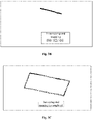
- the locating operation may be started, and if a locating position is read, a locating point icon (i.e., a dot in the figure) may be displayed on the electronic map.
- a locating point icon i.e., a dot in the figure
- N N is a positive integer
- a series of locating point icons i.e., dots in the figure
- the user may further press down a physical ton in the remote controller to record key locating positions.
- the locating operation is ended, and the screen keeps displaying the locating point icons in the electronic map where all locating positions obtained by surveying and mapping of this time are located.
- the locating point icons may be displayed to provide a flight region division reference for the user, and the user may trigger a confirmation operation, for example, clicking the locating point icons twice, pressing the locating point icons for long or reading the key locating positions selected by the user, to select the target positions from the locating positions.
- the locating positions corresponding to the locating point icons are confirmed to be the target positions.
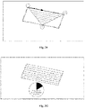
- locating positions corresponding to the locating point icons 1, 2, 3 and 4 may be determined to be target positions.
- the user may trigger a deletion operation to delete the target position, for example, clicking the locating point icon twice, to cancel the target position.
- the deletion operation for the locating point icons corresponding to the target positions is detected.
- positions of the locating point icons may be canceled to be determined as the target positions according to the deletion operation.
- the positions may be locating positions and may also be positions in the electronic map.
- a position of the locating point icon 4 may be canceled to be determined as the target position.
- the user may trigger a movement operation, for example, pressing the locating point icon for long, to move the target position.
- the movement operation for the locating point icons corresponding to the target positions is detected.
- the locating point icons may be moved in the electronic map according to the movement operation, and positions corresponding to the moved locating point icons are queried in a manner of geographic coding and the like as the target positions.
- the positions may be locating positions and may also be positions in the electronic map.
- the locating point icon 3 may be moved to another position.
- the locating point icons of the locating positions may be reserved, and new locating point icons may be generated for display.
- the abovementioned target position selection manner is only exemplary, another target position selection manner may be set according to a practical condition when the embodiment of the application is implemented, and there are no limits made in the embodiment of the application.
- those skilled in the art may further adopt another target position selection manner according to a practical requirement, which is not limited in the embodiment of the application.
- Step 203 a flight route is calculated according to the multiple target positions.
- the flight route of the unmanned aerial vehicle may be designed according to the multiple (usually three or more than three) selected target positions.
- the flight route is usually a set of waypoints, and the unmanned aerial vehicle may sequentially fly according to the set of the waypoints.
- the waypoints may include data of a waypoint sequence number, a waypoint type, a latitude and longitude, a flight height, a flight speed, a head type and the like.
- a data structure of a waypoint may be as follows:
- the flight route may include data of a waypoint count, waypoint array and the like of the route.
- a data structure of the flight route may be as follows:
- Step 203 may include the following sub-steps.
- Sub-step S21 multiple target positions are connected to generate a flight region.
- the target positions may be sequentially connected clockwise or counterclockwise in a straight line manner and the like according to a selection sequence of the target positions to generate a closed flight region.
- the target positions 1, 2, 3 and 4 may be sequentially connected to generate a closed quadrangular flight region.
- the flight route is calculated in the flight region.
- a starting route of the flight route may be calculated.
- a route from a first target position to a second target position may be determined as the starting route.
- a starting head may be the flight route (for example, the arrow direction) from 1 to 2.
- a route from the first target position to the last target position may also be the starting route, and the like, and there are no limits made in the embodiment of the application.
- parallel flight routes are designed by taking the starting route as a reference at an interval of a certain weight in the flight region.
- Endpoints (including starting endpoints and termination endpoints) of these parallel flight routes are on a boundary of the flight region.
- the starting endpoints and termination endpoints of adjacent flight routes are connected to form a connected flight route.
- widths between adjacent flight routes in the same direction in the flight region may be determined by a width of a body of the unmanned aerial vehicle and may also be determined according to a practical aerial photographing requirement of the unmanned aerial vehicle, and the like.
- the widths between the adjacent flight routes are smaller than 5 meters.
- an obstacle for example, an object influencing flight of the unmanned aerial vehicle like an electric pole, a lamp pole, a tree and a tall building
- a detouring region may be calculated for a position of the obstacle, a flight route is determined on a boundary of the detouring region, then the unmanned aerial vehicle may bypass the obstacle and continue flying, and a head of the unmanned aerial flight may also be ensured to completely cover the flight region as much as possible.
- the flight route is redesigned, that is, the multiple target positions are reconnected to generate a flight region and the flight route is calculated.
- Step 204 the flight route is sent to the unmanned aerial vehicle for flight according to the flight route.
- the flight route may be uploaded to the unmanned aerial vehicle through a protocol, for example, a Transmission Control Protocol (TCP)/Internet Protocol (IP), NetBios Enhanced User Interface NetBEUI and Internet work Packet Exchange (IPX/SPX), of a Hypertext Transfer Protocol (HTTP), and the unmanned aerial vehicle executes operations, for example, agricultural plant protection, according to the flight route.
- a protocol for example, a Transmission Control Protocol (TCP)/Internet Protocol (IP), NetBios Enhanced User Interface NetBEUI and Internet work Packet Exchange (IPX/SPX), of a Hypertext Transfer Protocol (HTTP)
- TCP Transmission Control Protocol
- IP Internet Protocol
- IPX/SPX Internet work Packet Exchange
- HTTP Hypertext Transfer Protocol
- the user may press a specified physical button on the remote controller for long (for example, 3-second long press for starting operations), thereby triggering the uploading instruction for the flight route.
- a specified physical button on the remote controller for long (for example, 3-second long press for starting operations), thereby triggering the uploading instruction for the flight route.
- the locating module is integrated in the remote controller, and then the locating operation may be executed on the remote controller to obtain the locating data, thereby directly determining the target positions, calculating the flight route and controlling flight of the unmanned aerial vehicle.
- the remote controller is integrated with three functions of flight region (for example, farmland) surveying and mapping, route drawing and remote control operation, so that, when the unmanned aerial vehicle is used for operations of plant protection and the like, only the remote controller is required to be carried, carrying of multiple sets of equipment is avoided, and hardware cost is reduced.
- remote control equipment is integrated with the surveying and mapping function, carrying of multiple kinds of equipment is avoided, that is, data exchange among multiple kinds of equipment is avoided, convenience for operation is further improved, operation efficiency of the unmanned aerial vehicle is improved, moreover, a probability of a data sending error during data exchange is reduced, and operation reliability of the unmanned aerial vehicle is improved.
- FIG. 4 a structure block diagram of an embodiment of a device for controlling flight of an unmanned aerial vehicle according to the application is shown.
- the following modules may specifically be included:
- the locating data acquisition module 401 may include the following submodules:
- the target position determination module 402 may include the following submodules:
- the target position determination module 402 may further include the following submodules:
- the target position determination module 402 may further include the following submodules:
- the flight route calculation module 403 may include the following submodules:
- the remote controller may include a locating module 510, a display 520 and a flight control device 530 for an unmanned aerial vehicle, wherein the flight control device 530 for the unmanned aerial vehicle may include the following modules:
- the locating data acquisition module 531 may include the following submodules:
- the target position determination module 532 may include the following submodules:
- the target position determination module 532 may further include the following submodules:
- the target position determination module 532 may further include the following submodules:
- the flight route calculation module 533 may include the following submodules:
- a remote controller which includes:
- a remote controller which includes:
- Fig. 6 is a block diagram of a flight control device 600 according to an exemplary embodiment.
- the device 600 may be an unmanned aerial vehicle, an unmanned vehicle, an unmanned ship, a mobile phone, a computer, a digital broadcast terminal, a messaging device, a gaming console, a tablet, a medical device, exercise equipment, a personal digital assistant, and the like.
- the device 600 may include one or more of the following components: a processing component 602, a memory 604, a power component 606, a multimedia component 608, an audio component 610, an Input/Output (I/O) interface 612, a sensor component 614, and a communication component 616.
- the processing component 602 typically controls overall operations of the device 600, such as the operations associated with display, telephone calls, data communications, camera operations, and recording operations.
- the processing component 602 may include one or more processors 620 to execute instructions to perform all or part of the steps in the abovementioned method.
- the processing component 602 may include one or more modules which facilitate interaction between the processing component 602 and the other components.
- the processing component 602 may include a multimedia module to facilitate interaction between the multimedia component 608 and the processing component 602.
- the memory 604 is configured to store various types of data to support the operation of the device 600. Examples of such data include instructions for any application programs or methods operated on the device 600, contact data, phonebook data, messages, pictures, video, etc.
- the memory 604 may be implemented by any type of volatile or non-volatile memory devices, or a combination thereof, such as a Static Random Access Memory (SRAM), an Electrically Erasable Programmable Read-Only Memory (EEPROM), an Erasable Programmable Read-Only Memory (EPROM), a Programmable Read-Only Memory (PROM), a Read-Only Memory (ROM), a magnetic memory, a flash memory, and a magnetic or optical disk.
- SRAM Static Random Access Memory
- EEPROM Electrically Erasable Programmable Read-Only Memory
- EPROM Erasable Programmable Read-Only Memory
- PROM Programmable Read-Only Memory
- ROM Read-Only Memory
- magnetic memory a magnetic memory
- flash memory and a magnetic or optical disk.
- the power component 606 provides power for various components of the device 600.
- the power component 606 may include a power management system, one or more power supplies, and other components associated with the generation, management and distribution of power for the device 600.
- the multimedia component 608 includes a screen providing an output interface between the device 600 and a user.
- the screen may include a Liquid Crystal Display (LCD) and a Touch Panel (TP). If the screen includes the TP, the screen may be implemented as a touch screen to receive an input signal from the user.
- the TP includes one or more touch sensors to sense touches, swipes and gestures on the TP. The touch sensors may not only sense a boundary of a touch or swipe action, but also detect a duration and pressure associated with the touch or swipe action.
- the multimedia component 608 includes a front camera and/or a rear camera.
- the front camera and/or the rear camera may receive external multimedia data when the device 600 is in an operation mode, such as a photographing mode or a video mode.
- an operation mode such as a photographing mode or a video mode.
- Each of the front camera and the rear camera may be a fixed optical lens system or have focusing and optical zooming capabilities.
- the audio component 610 is configured to output and/or input an audio signal.
- the audio component 610 includes a Microphone (MIC), and the MIC is configured to receive an external audio signal when the device 600 is in the operation mode, such as a call mode, a recording mode and a voice recognition mode.
- the received audio signal may be further stored in the memory 604 or sent through the communication component 616.
- the audio component 610 further includes a speaker configured to output the audio signal.
- the I/O interface 612 provides an interface between the processing component 602 and a peripheral interface module, and the peripheral interface module may be a keyboard, a click wheel, a button and the like.
- the button may include, but not limited to: a home button, a volume button, a starting button and a locking button.
- the sensor component 614 includes one or more sensors configured to provide status assessment in various aspects for the device 600. For instance, the sensor component 614 may detect an on/off status of the device 600 and relative positioning of components, such as a display and small keyboard of the device 600, and the sensor component 614 may further detect a change in a position of the device 600 or a component of the device 600, presence or absence of contact between the user and the device 600, orientation or acceleration/deceleration of the device 600 and a change in temperature of the device 600.
- the sensor component 614 may include a proximity sensor configured to detect presence of an object nearby without any physical contact.
- the sensor component 614 may also include a light sensor, such as a Complementary Metal Oxide Semiconductor (CMOS) or Charge Coupled Device (CCD) image sensor, configured for use in an imaging application.
- CMOS Complementary Metal Oxide Semiconductor
- CCD Charge Coupled Device
- the sensor component 614 may also include a locating module, an acceleration sensor, a gyroscope sensor, a magnetic sensor, a pressure sensor or a temperature sensor.
- the communication component 616 is configured to facilitate wired or wireless communication between the device 600 and other equipment.
- the device 600 may access a communication-standard-based wireless network, such as a WIFI network, a 2nd-Generation (2G) or 3rd-Generation (3G) network or a combination thereof.
- the communication component 616 receives a broadcast signal or broadcast associated information from an external broadcast management system through a broadcast channel.
- the communication component 616 further includes a Near Field Communication (NFC) module to facilitate short-range communication.
- NFC Near Field Communication
- the NFC module may be implemented on the basis of a Radio Frequency Identification (RFID) technology, an Infrared Data Association (IrDA) technology, an Ultra-WideBand (UWB) technology, a BT technology and another technology.
- RFID Radio Frequency Identification
- IrDA Infrared Data Association
- UWB Ultra-WideBand
- the device 600 may be implemented by one or more Application Specific Integrated Circuits (ASICs), Digital Signal Processors (DSPs), Digital Signal Processing Devices (DSPDs), Programmable Logic Devices (PLDs), Field Programmable Gate Arrays (FPGAs), controllers, micro-controllers, microprocessors or other electronic components, and is configured to execute the abovementioned method.
- ASICs Application Specific Integrated Circuits
- DSPs Digital Signal Processors
- DSPDs Digital Signal Processing Devices
- PLDs Programmable Logic Devices
- FPGAs Field Programmable Gate Arrays
- controllers micro-controllers, microprocessors or other electronic components, and is configured to execute the abovementioned method.
- a non-transitory computer-readable storage medium including an instruction such as the memory 604 including an instruction, and the instruction may be executed by the processor 620 of the device 600 to implement the abovementioned method.
- the non-transitory computer-readable storage medium may be a ROM, a Random Access Memory (RAM), a Compact Disc Read-Only Memory (CD-ROM), a magnetic tape, a floppy disc, optical data storage equipment and the like.
- the embodiment of the application may be provided as a method, a device or a computer program product. Therefore, the embodiment of the application may adopt a form of pure hardware embodiment, pure software embodiment and combined software and hardware embodiment. Moreover, the embodiment of the application may adopt a form of computer program product implemented on one or more computer-available storage media (including, but not limited to, a disk memory, a CD-ROM and an optical memory) including computer-available program codes.
- a computer-available storage media including, but not limited to, a disk memory, a CD-ROM and an optical memory
- These computer program instructions may be provided for a universal computer, a dedicated computer, an embedded processor or a processor of other programmable data processing equipment to generate a machine, so that a device for realizing a function specified in one flow or more flows in the flowcharts and/or one block or more blocks in the block diagrams is generated by the instructions executed through the computer or the processor of the other programmable data processing equipment.
- These computer program instructions may also be stored in a computer-readable memory capable of guiding the computer or the other programmable data processing equipment to work in a specific manner, so that a product including an instruction device may be generated by the instructions stored in the computer-readable memory, the instruction device realizing the function specified in one flow or many flows in the flowcharts and/or one block or many blocks in the block diagrams.
- These computer program instructions may further be loaded onto the computer or the other programmable data processing equipment, so that a series of operating steps are executed on the computer or the other programmable data processing equipment to generate processing implemented by the computer, and steps for realizing the function specified in one flow or many flows in the flowcharts and/or one block or many blocks in the block diagrams are provided by the instructions executed on the computer or the other programmable data processing equipment.
Landscapes
- Engineering & Computer Science (AREA)
- Aviation & Aerospace Engineering (AREA)
- Physics & Mathematics (AREA)
- General Physics & Mathematics (AREA)
- Radar, Positioning & Navigation (AREA)
- Remote Sensing (AREA)
- Automation & Control Theory (AREA)
- General Engineering & Computer Science (AREA)
- Computer Networks & Wireless Communication (AREA)
- Navigation (AREA)
- Traffic Control Systems (AREA)
- Control Of Position, Course, Altitude, Or Attitude Of Moving Bodies (AREA)
- Computing Systems (AREA)
- Mathematical Physics (AREA)
- Theoretical Computer Science (AREA)
Claims (13)
- Verfahren zum Steuern des Flugs eines unbemannten Luftfahrzeugs, das Folgendes umfasst:Erfassen mehrerer Teile von Ortungsdaten, die durch einen Ortungsvorgang in einer Fernsteuereinheit erhalten werden, wobei die mehreren Teile von Ortungsdaten durch einen Ortungsvorgang bestimmt werden, der durch ein Ortungsmodul in der Fernsteuereinheit (201) durchgeführt wird, und dann, wenn die Fernsteuereinheit sich an einem Rand eines Flugbereichs bewegt, der Ortungsvorgang durch die Fernsteuereinheit gemäß einer bestimmten Frequenz ausgeführt wird;Bestimmen mehrerer Zielpositionen gemäß den mehreren Teilen von Ortungsdaten (202);Berechnen einer Flugroute gemäß den mehreren Zielpositionen (203) undSenden der Flugroute zum unbemannten Luftfahrzeug zum Flug gemäß der Flugroute (204).
- Verfahren nach Anspruch 1, wobei der Schritt des Erfassens der mehreren Teile von Ortungsdaten, die durch den Ortungsvorgang in der Fernsteuereinheit erhalten werden, Folgendes umfasst:Lesen von mehreren Ausgangsortungsparametern, die durch den Ortungsvorgang über die Fernsteuereinheit in der Fernsteuereinheit erhalten werden; undKapseln der mehreren Ausgangsortungsparameter in den mehreren Teilen von Ortungsdaten gemäß einem festgelegten Format.
- Verfahren nach Anspruch 1 oder 2, wobei der Schritt des Bestimmens der mehreren Zielpositionen gemäß den mehreren Teilen von Ortungsdaten Folgendes umfasst:Anzeigen einer elektronischen Karte;Lesen mehrerer Ortungspositionen aus den mehreren Teilen von Ortungsdaten gemäß dem festgelegten Format;Anzeigen von Ortungspunktsymbolen in der elektronischen Karte gemäß den mehreren Ortungspositionen undBestätigen dann, wenn eine Bestätigungsoperation für die Ortungspunktsymbole detektiert wird, dass die Ortungspositionen, die den Ortungspunktsymbolen entsprechen, die Zielpositionen sind.
- Verfahren nach Anspruch 3, wobei der Schritt des Bestimmens der mehreren Zielpositionen gemäß den mehreren Teilen von Ortungsdaten ferner Folgendes umfasst:Detektieren einer Löschoperation für die Ortungspunktsymbole, die den Zielpositionen entsprechen; undUnterdrücken gemäß der Löschoperation, dass Positionen der Ortungspunktsymbole als die Zielpositionen bestimmt werden.
- Verfahren nach Anspruch 3, wobei der Schritt des Bestimmens der mehreren Zielpositionen gemäß den mehreren Teilen von Ortungsdaten ferner Folgendes umfasst:Detektieren einer Bewegungsoperation für die Ortungspunktsymbole, die den Zielpositionen entsprechen;Bewegen der Ortungspunktsymbole in der elektronischen Karte gemäß der Bewegungsoperation undAbfragen von Positionen, die den bewegten Ortungspunktsymbolen entsprechen, als die Zielpositionen.
- Verfahren nach Anspruch 1 oder 2 oder 4 oder 5, wobei der Schritt des Berechnens der Flugroute gemäß den mehreren Zielpositionen Folgendes umfasst:Verbinden der mehreren Zielpositionen, um einen Flugbereich zu erzeugen; undBerechnen der Flugroute im Flugbereich.
- Vorrichtung zum Steuern des Flugs eines unbemannten Luftfahrzeugs, die Folgendes umfasst:ein Ortungsdatenerfassungsmodul (401), das konfiguriert ist, mehrere Teile von Ortungsdaten, die durch einen Ortungsvorgang in einer Fernsteuereinheit erhalten werden, zu erfassen, wobei die mehreren Teile von Ortungsdaten durch einen Ortungsvorgang bestimmt werden, der durch ein Ortungsmodul in der Fernsteuereinheit durchgeführt wird, und dann, wenn die Fernsteuereinheit sich an einem Rand eines Flugbereichs bewegt, der Ortungsvorgang durch die Fernsteuereinheit gemäß einer bestimmten Frequenz ausgeführt wird;ein Zielpositionsbestimmungsmodul (402), das konfiguriert ist, mehrere Zielpositionen gemäß den mehreren Teilen von Ortungsdaten zu bestimmen;ein Flugroutenberechnungsmodul (403), das konfiguriert ist, eine Flugroute gemäß den mehreren Zielpositionen zu berechnen; undein Flugroutensendemodul (404), das konfiguriert ist, die Flugroute zum Flug gemäß der Flugroute zum unbemannten Luftfahrzeug zu senden.
- Vorrichtung nach Anspruch 7, wobei das Ortungsdatenerfassungsmodul (401) Folgendes umfasst:ein Ausgangsortungsparameterlese-Untermodul, das konfiguriert ist, mehrere Ausgangsortungsparameter, die durch den Ortungsvorgang über die Fernsteuereinheit in der Fernsteuereinheit erhalten werden, zu lesen; undein Positionierungsdatenkapselungs-Untermodul, das konfiguriert ist, die mehreren Ausgangsortungsparameter gemäß einem festgelegten Format in die mehreren Teile von Ortungsdaten zu kapseln.
- Vorrichtung nach Anspruch 7 oder 8, wobei das Zielpositionsbestimmungsmodul (402) Folgendes umfasst:ein elektronisches Kartenanzeigeuntermodul, das konfiguriert ist, eine elektronische Karte anzuzeigen;ein Ortungspositionslese-Untermodul, das konfiguriert ist, mehrere Ortungspositionen gemäß dem festgelegten Format aus den mehreren Teilen von Ortungsdaten zu lesen;eine Ortungspunktsymbolanzeige-Untermodul, das konfiguriert ist, Ortungspunktsymbole gemäß den mehreren Ortungspositionen in der elektronischen Karte anzuzeigen; undein Positionsbestimmungs-Untermodul, das konfiguriert ist, dann, wenn eine Bestätigungsoperation für die Ortungspunktsymbole detektiert wird, zu bestätigen, dass die Ortungspositionen, die den Ortungspunktsymbolen entsprechen, die Zielpositionen sind.
- Vorrichtung nach Anspruch 9, wobei das Zielpositionsbestimmungsmodul (402) ferner Folgendes umfasst:ein Löschoperationsdetektions-Untermodul, das konfiguriert ist, eine Löschoperation für die Ortungspunktsymbole, die den Zielpositionen entsprechen, zu detektieren; undein Zielpositionslösch-Untermodul, das konfiguriert ist, gemäß der Löschoperation zu unterdrücken, dass Positionen der Ortungspunktsymbole als die Zielpositionen bestimmt werden.
- Vorrichtung nach Anspruch 9, wobei das Zielpositionsbestimmungsmodul (402) ferner Folgendes umfasst:ein Bewegungsbetriebsdetektions-Untermodul, das konfiguriert ist, eine Bewegungsoperation für die Ortungspunktsymbole, die den Zielpositionen entsprechen, zu detektieren;ein Ortungspunktsymbolbewegungs-Untermodul, das konfiguriert ist, die Ortungspunktsymbole in der elektronischen Karte gemäß der Bewegungsoperation zu bewegen; undein Positionsabfrageuntermodul, das konfiguriert ist, Positionen, die den bewegten Ortungspunktsymbolen entsprechen, als die Zielpositionen abzufragen.
- Vorrichtung nach Anspruch 7 oder 8 oder 10 oder 11, wobei das Flugroutenberechnungsmodul (403) Folgendes umfasst:ein Flugbereichserzeugungs-Untermodul, das konfiguriert ist, die mehreren Zielpositionen zu verbinden, um einen Flugbereich erzeugen; undein Routenberechnungsuntermodul, das konfiguriert ist, die Flugroute im Flugbereich zu berechnen.
- Fernsteuereinheit, die ein Ortungsmodul, eine Anzeigevorrichtung und die Flugsteuervorrichtung für das unbemannte Luftfahrzeug nach einem der Ansprüche 8-12 umfasst.
Applications Claiming Priority (2)
| Application Number | Priority Date | Filing Date | Title |
|---|---|---|---|
| CN201610368832.8A CN106054917A (zh) | 2016-05-27 | 2016-05-27 | 一种无人飞行器的飞行控制方法、装置和遥控器 |
| PCT/CN2017/086183 WO2017202381A1 (zh) | 2016-05-27 | 2017-05-26 | 一种无人飞行器的飞行控制方法、装置和遥控器 |
Publications (3)
| Publication Number | Publication Date |
|---|---|
| EP3467609A1 EP3467609A1 (de) | 2019-04-10 |
| EP3467609A4 EP3467609A4 (de) | 2020-01-22 |
| EP3467609B1 true EP3467609B1 (de) | 2022-12-07 |
Family
ID=57171311
Family Applications (1)
| Application Number | Title | Priority Date | Filing Date |
|---|---|---|---|
| EP17802227.3A Active EP3467609B1 (de) | 2016-05-27 | 2017-05-26 | Flugsteuerungsverfahren und -vorrichtung für unbemanntes luftfahrzeug und fernsteuerung |
Country Status (7)
| Country | Link |
|---|---|
| US (1) | US10921803B2 (de) |
| EP (1) | EP3467609B1 (de) |
| JP (1) | JP6753957B2 (de) |
| KR (1) | KR20190006517A (de) |
| CN (1) | CN106054917A (de) |
| AU (1) | AU2017270979A1 (de) |
| WO (1) | WO2017202381A1 (de) |
Families Citing this family (43)
| Publication number | Priority date | Publication date | Assignee | Title |
|---|---|---|---|---|
| CN106054917A (zh) | 2016-05-27 | 2016-10-26 | 广州极飞电子科技有限公司 | 一种无人飞行器的飞行控制方法、装置和遥控器 |
| WO2018080961A1 (en) * | 2016-10-24 | 2018-05-03 | Agco International Gmbh | Land mapping and guidance system |
| CN106568433B (zh) * | 2016-10-28 | 2020-11-03 | 易瓦特科技股份公司 | 一种设置飞行轨迹的方法和装置 |
| WO2018076372A1 (zh) * | 2016-10-31 | 2018-05-03 | 深圳市大疆创新科技有限公司 | 一种航点编辑方法、装置、设备及飞行器 |
| CN107636592B (zh) * | 2016-11-14 | 2021-03-16 | 深圳市大疆创新科技有限公司 | 航道规划方法、控制端、飞行器及航道规划系统 |
| CN106716062B (zh) * | 2016-11-24 | 2019-03-12 | 深圳市大疆创新科技有限公司 | 农业无人飞行器的航线规划方法及地面控制端 |
| WO2018094670A1 (zh) * | 2016-11-24 | 2018-05-31 | 深圳市大疆创新科技有限公司 | 农业无人飞行器的控制方法、地面控制端及存储介质 |
| CN106774392B (zh) * | 2016-12-13 | 2020-05-01 | 中国南方电网有限责任公司超高压输电公司检修试验中心 | 一种电力线路巡检过程中飞行路径的动态规划方法 |
| WO2018112831A1 (zh) * | 2016-12-22 | 2018-06-28 | 深圳市大疆创新科技有限公司 | 无人机及其控制方法 |
| CN106713792B (zh) * | 2017-01-13 | 2020-05-22 | 狼天科技(深圳)有限公司 | 一种处理参数的方法和设备 |
| CN106814750A (zh) * | 2017-02-14 | 2017-06-09 | 北京小米移动软件有限公司 | 无人机飞行控制方法及装置 |
| CN107272729B (zh) * | 2017-06-06 | 2021-01-22 | 上海工程技术大学 | 一种基于路由器的无人机巡航系统 |
| CN109426273A (zh) * | 2017-08-29 | 2019-03-05 | 深圳市道通智能航空技术有限公司 | 一种飞行器控制方法及装置 |
| WO2019119187A1 (zh) * | 2017-12-18 | 2019-06-27 | 深圳市大疆创新科技有限公司 | 一种无人机的航线规划方法、控制设备及存储介质 |
| WO2019119186A1 (zh) * | 2017-12-18 | 2019-06-27 | 深圳市大疆创新科技有限公司 | 一种无人机的航点编辑方法、控制设备及存储介质 |
| DE102018120675A1 (de) * | 2018-08-23 | 2020-02-27 | Autel Robotics Europe Gmbh | Verfahren, Vorrichtung und System zum Betreiben von Wegpunkt, Bodenstation und computerlesbarem Speichermedium |
| CN109144100B (zh) * | 2018-09-03 | 2021-06-25 | 南京嘉谷初成通信科技有限公司 | 喷洒控制方法、装置、地面站及存储介质 |
| CN111095154A (zh) * | 2018-09-25 | 2020-05-01 | 深圳市大疆软件科技有限公司 | 农业无人飞行器的控制方法、控制端及存储介质 |
| JP7270265B2 (ja) * | 2018-10-03 | 2023-05-10 | 株式会社ナイルワークス | 運転経路生成装置、運転経路生成方法、運転経路生成プログラム、およびドローン |
| CN109753062B (zh) * | 2018-12-14 | 2023-07-21 | 广州极飞科技股份有限公司 | 为作业设备设置作业路线的方法和控制设备 |
| CN110164110A (zh) * | 2019-04-23 | 2019-08-23 | 天津航天中为数据系统科技有限公司 | 一种用于植保无人机at9s遥控器的数据处理方法 |
| CN110262544B (zh) * | 2019-05-30 | 2022-05-03 | 北京百年初心科技有限公司 | 一种用于纳米纤维生产的监察机器人 |
| CN110597277A (zh) * | 2019-08-20 | 2019-12-20 | 杜书豪 | 一种智能飞行设备及其人机交互方法 |
| CN110456820B (zh) * | 2019-08-22 | 2021-07-27 | 江苏农林职业技术学院 | 基于超带宽无线定位的农药喷施系统及控制方法 |
| CN111750857B (zh) * | 2019-10-24 | 2021-12-28 | 广州极飞科技股份有限公司 | 航线生成方法、装置、终端及存储介质 |
| CN112799423A (zh) * | 2019-10-24 | 2021-05-14 | 广州极飞科技股份有限公司 | 操控组件及植保系统 |
| CN112292648B (zh) * | 2019-11-19 | 2024-08-20 | 深圳市大疆创新科技有限公司 | 飞行控制方法、设备及系统 |
| CN110989682B (zh) * | 2019-12-30 | 2021-06-01 | 福州大学 | 基于单基站的无人机精准降落方法 |
| JP7412037B2 (ja) * | 2020-02-20 | 2024-01-12 | 株式会社ナイルワークス | ドローンシステム、操作器および作業エリアの定義方法 |
| KR102391207B1 (ko) * | 2020-03-12 | 2022-04-27 | 주식회사 넥스트코어테크놀로지 | 3d 모델링 기반 작업자 위치 관리 시스템 |
| CN111443727A (zh) * | 2020-03-18 | 2020-07-24 | 东北农业大学 | 一种多旋翼无人机的飞行控制管理系统及方法 |
| WO2021212501A1 (zh) * | 2020-04-24 | 2021-10-28 | 深圳市大疆创新科技有限公司 | 轨迹生成方法、遥控终端、可移动平台、系统及计算机可读存储介质 |
| WO2021220409A1 (ja) * | 2020-04-28 | 2021-11-04 | 株式会社ナイルワークス | エリア編集システム、ユーザインターフェース装置および作業エリアの編集方法 |
| CN111461464B (zh) * | 2020-05-06 | 2021-06-08 | 农业农村部南京农业机械化研究所 | 一种植保无人飞机集群作业任务分配方法和装置 |
| CN111736624B (zh) * | 2020-05-12 | 2023-12-22 | 萧县航迅信息技术有限公司 | 基于Cell-ID无人机城市飞行航线规划系统及方法 |
| CN112863252B (zh) * | 2021-01-18 | 2022-12-02 | 北京京东乾石科技有限公司 | 飞行器降落控制方法、装置、系统、设备及存储介质 |
| US12189042B1 (en) * | 2021-03-31 | 2025-01-07 | Snap Inc. | UAV with GPS spoofing detection |
| CN113515137A (zh) * | 2021-04-09 | 2021-10-19 | 北京三快在线科技有限公司 | 一种无人机控制方法、装置、存储介质及电子设备 |
| CN113785816B (zh) * | 2021-09-16 | 2023-03-17 | 江苏食品药品职业技术学院 | 一种基于bds技术的精准喷农药装置 |
| CN113778138A (zh) * | 2021-09-22 | 2021-12-10 | 青海三新农电有限责任公司 | 一种无人机飞行航线的确定方法 |
| CN115825857A (zh) * | 2022-12-29 | 2023-03-21 | 亿航智能设备(广州)有限公司 | 一种无人机定位方法、装置及其设备 |
| CN119292320B (zh) * | 2023-09-19 | 2025-09-23 | 航天科工火箭技术有限公司 | 一种确定火箭目标角精度的方法、装置、介质及设备 |
| CN118811141B (zh) * | 2024-06-21 | 2025-09-30 | 山东科技大学 | 一种基于多源信息融合监测的智慧农业无人机系统 |
Family Cites Families (25)
| Publication number | Priority date | Publication date | Assignee | Title |
|---|---|---|---|---|
| SE0300871D0 (sv) * | 2003-03-27 | 2003-03-27 | Saab Ab | Waypoint navigation |
| DE602004018910D1 (de) * | 2004-07-03 | 2009-02-26 | Saab Ab | System und Verfahren zur Steuerung eines Flugzeugs während des Fluges |
| US20100286859A1 (en) * | 2008-11-18 | 2010-11-11 | Honeywell International Inc. | Methods for generating a flight plan for an unmanned aerial vehicle based on a predicted camera path |
| KR101056377B1 (ko) | 2009-02-17 | 2011-08-12 | 경상대학교산학협력단 | 비행장치 제어단말, 비행장치 제어방법 및 비행장치 제어 시스템 |
| KR101117207B1 (ko) | 2010-07-12 | 2012-03-16 | 한국항공대학교산학협력단 | 스마트폰을 이용한 무인비행체 자동 및 수동 조종시스템 |
| CN102854886B (zh) | 2012-08-29 | 2016-01-20 | 深圳一电科技有限公司 | 飞行线路编辑及控制的方法和装置 |
| CN202838027U (zh) * | 2012-09-28 | 2013-03-27 | 佛山市安尔康姆航拍科技有限公司 | 一种无人飞行器一体化地面站设备 |
| CN102955478B (zh) * | 2012-10-24 | 2016-01-20 | 深圳一电科技有限公司 | 无人机飞行控制方法及系统 |
| US8930044B1 (en) * | 2012-12-28 | 2015-01-06 | Google Inc. | Multi-part navigation process by an unmanned aerial vehicle for navigating to a medical situatiion |
| US9382003B2 (en) * | 2013-03-24 | 2016-07-05 | Bee Robotics Corporation | Aerial farm robot system for crop dusting, planting, fertilizing and other field jobs |
| US10410537B2 (en) * | 2013-08-30 | 2019-09-10 | Insitu, Inc. | Unmanned vehicle simulation |
| CN103699135B (zh) * | 2014-01-03 | 2016-04-06 | 中南大学 | 无人直升机农药喷洒农田作业区域的航迹自动规划方法 |
| DE102014107401A1 (de) | 2014-05-26 | 2015-11-26 | Knorr-Bremse Systeme für Nutzfahrzeuge GmbH | Scheibenbremse, Bremssattel und Bremsbelagsatz für eine Scheibenbremse |
| CN104035446B (zh) * | 2014-05-30 | 2017-08-25 | 深圳市大疆创新科技有限公司 | 无人机的航向生成方法和系统 |
| WO2015180133A1 (zh) * | 2014-05-30 | 2015-12-03 | 深圳市大疆创新科技有限公司 | 无人机的航向生成方法和系统 |
| US10402835B2 (en) * | 2014-07-16 | 2019-09-03 | Raytheon Company | Agricultural situational awareness tool |
| BR112017003678B1 (pt) | 2014-08-22 | 2023-04-18 | The Climate Corporation | Método e sistema para monitoramento agronômico e agrícola |
| CN104503464B (zh) * | 2014-12-30 | 2017-01-18 | 中南大学 | 基于计算机的凸多边形农田无人机喷洒作业航迹规划方法 |
| CN105159319B (zh) | 2015-09-29 | 2017-10-31 | 广州极飞科技有限公司 | 一种无人机的喷药方法及无人机 |
| CN105241470A (zh) * | 2015-11-12 | 2016-01-13 | 上海卓易科技股份有限公司 | 一种获取路线的方法及装置 |
| CN205210692U (zh) * | 2015-12-04 | 2016-05-04 | 中国航空工业集团公司沈阳飞机设计研究所 | 一种小型无人机航路规划系统 |
| CN205239936U (zh) * | 2015-12-21 | 2016-05-18 | 零度智控(北京)智能科技有限公司 | 一种农业喷洒无人机装置 |
| CN105468024B (zh) * | 2016-01-29 | 2020-11-17 | 北京臻迪机器人有限公司 | 一种无人机控制方法和装置 |
| CN105549620B (zh) * | 2016-02-25 | 2019-07-19 | 上海未来伙伴机器人有限公司 | 飞行器遥控棒及控制飞行器飞行的方法 |
| CN106054917A (zh) | 2016-05-27 | 2016-10-26 | 广州极飞电子科技有限公司 | 一种无人飞行器的飞行控制方法、装置和遥控器 |
-
2016
- 2016-05-27 CN CN201610368832.8A patent/CN106054917A/zh active Pending
-
2017
- 2017-05-26 AU AU2017270979A patent/AU2017270979A1/en active Pending
- 2017-05-26 JP JP2018562165A patent/JP6753957B2/ja not_active Expired - Fee Related
- 2017-05-26 US US16/304,938 patent/US10921803B2/en not_active Expired - Fee Related
- 2017-05-26 KR KR1020187035477A patent/KR20190006517A/ko not_active Ceased
- 2017-05-26 EP EP17802227.3A patent/EP3467609B1/de active Active
- 2017-05-26 WO PCT/CN2017/086183 patent/WO2017202381A1/zh not_active Ceased
Also Published As
| Publication number | Publication date |
|---|---|
| AU2017270979A1 (en) | 2018-12-20 |
| JP2019526479A (ja) | 2019-09-19 |
| CN106054917A (zh) | 2016-10-26 |
| KR20190006517A (ko) | 2019-01-18 |
| JP6753957B2 (ja) | 2020-09-09 |
| EP3467609A1 (de) | 2019-04-10 |
| US20190371184A1 (en) | 2019-12-05 |
| EP3467609A4 (de) | 2020-01-22 |
| WO2017202381A1 (zh) | 2017-11-30 |
| US10921803B2 (en) | 2021-02-16 |
Similar Documents
| Publication | Publication Date | Title |
|---|---|---|
| EP3467609B1 (de) | Flugsteuerungsverfahren und -vorrichtung für unbemanntes luftfahrzeug und fernsteuerung | |
| US20240295626A1 (en) | Positioning method and apparatus, and storage medium | |
| US11164379B2 (en) | Augmented reality positioning method and apparatus for location-based service LBS | |
| US10830601B2 (en) | User controlled directional interface | |
| US20190240839A1 (en) | Robot and operation method therefor | |
| CN113064185B (zh) | 一种定位方法、终端及服务器 | |
| EP3355596A1 (de) | Positionierungsinformationsverarbeitungsverfahren und -vorrichtung | |
| WO2019036939A1 (zh) | 一种定位方法及装置 | |
| US20210247520A1 (en) | Broadcast Transmission of Information Indicative of a Pseudorange Correction | |
| CN108151748B (zh) | 飞行装置测绘作业航线规划方法、装置和终端 | |
| US20190003840A1 (en) | Map registration point collection with mobile drone | |
| CN112334791B (zh) | 定位方法、系统、遥控设备及rtk模块 | |
| WO2014020994A1 (ja) | 気象情報表示システム、ヒューマンナビゲーション装置、及び気象情報表示方法 | |
| JP2020532209A (ja) | 測位データを報告する方法 | |
| CN105157720A (zh) | 一种基于位置共享的导航方法及装置 | |
| WO2022242717A1 (zh) | 一种地图选择方法、自移动设备、电子终端 | |
| US9942698B2 (en) | Harvesting communication parameter observations in GNSS-denied environments | |
| CN105357640A (zh) | 定位的方法和装置 | |
| CN105744482A (zh) | 信号转发器 | |
| KR102169688B1 (ko) | 장소정보 제공방법 및 그 시스템 | |
| CN114449647A (zh) | 定位方法及装置 | |
| US20190287390A1 (en) | Information processing device and method, and recording medium | |
| CN113836963A (zh) | 寻车方法、移动终端及寻车系统 | |
| CN121645457A (zh) | 定位方法及系统、中枢设备、存储介质及程序产品 | |
| CN119893661A (zh) | 定位方法及装置、电子设备、存储介质 |
Legal Events
| Date | Code | Title | Description |
|---|---|---|---|
| STAA | Information on the status of an ep patent application or granted ep patent |
Free format text: STATUS: THE INTERNATIONAL PUBLICATION HAS BEEN MADE |
|
| PUAI | Public reference made under article 153(3) epc to a published international application that has entered the european phase |
Free format text: ORIGINAL CODE: 0009012 |
|
| STAA | Information on the status of an ep patent application or granted ep patent |
Free format text: STATUS: REQUEST FOR EXAMINATION WAS MADE |
|
| 17P | Request for examination filed |
Effective date: 20181128 |
|
| AK | Designated contracting states |
Kind code of ref document: A1 Designated state(s): AL AT BE BG CH CY CZ DE DK EE ES FI FR GB GR HR HU IE IS IT LI LT LU LV MC MK MT NL NO PL PT RO RS SE SI SK SM TR |
|
| AX | Request for extension of the european patent |
Extension state: BA ME |
|
| DAV | Request for validation of the european patent (deleted) | ||
| DAX | Request for extension of the european patent (deleted) | ||
| RIN1 | Information on inventor provided before grant (corrected) |
Inventor name: CHEN, JIAXIANG Inventor name: XIE, ANPING Inventor name: XIAO, YANQIANG |
|
| A4 | Supplementary search report drawn up and despatched |
Effective date: 20191219 |
|
| RIC1 | Information provided on ipc code assigned before grant |
Ipc: G05D 1/10 20060101AFI20191213BHEP Ipc: G05D 1/02 20060101ALI20191213BHEP Ipc: G05D 1/00 20060101ALI20191213BHEP |
|
| STAA | Information on the status of an ep patent application or granted ep patent |
Free format text: STATUS: EXAMINATION IS IN PROGRESS |
|
| 17Q | First examination report despatched |
Effective date: 20210604 |
|
| GRAP | Despatch of communication of intention to grant a patent |
Free format text: ORIGINAL CODE: EPIDOSNIGR1 |
|
| STAA | Information on the status of an ep patent application or granted ep patent |
Free format text: STATUS: GRANT OF PATENT IS INTENDED |
|
| INTG | Intention to grant announced |
Effective date: 20220706 |
|
| GRAS | Grant fee paid |
Free format text: ORIGINAL CODE: EPIDOSNIGR3 |
|
| GRAA | (expected) grant |
Free format text: ORIGINAL CODE: 0009210 |
|
| STAA | Information on the status of an ep patent application or granted ep patent |
Free format text: STATUS: THE PATENT HAS BEEN GRANTED |
|
| AK | Designated contracting states |
Kind code of ref document: B1 Designated state(s): AL AT BE BG CH CY CZ DE DK EE ES FI FR GB GR HR HU IE IS IT LI LT LU LV MC MK MT NL NO PL PT RO RS SE SI SK SM TR |
|
| REG | Reference to a national code |
Ref country code: GB Ref legal event code: FG4D |
|
| REG | Reference to a national code |
Ref country code: CH Ref legal event code: EP Ref country code: AT Ref legal event code: REF Ref document number: 1536667 Country of ref document: AT Kind code of ref document: T Effective date: 20221215 |
|
| REG | Reference to a national code |
Ref country code: DE Ref legal event code: R096 Ref document number: 602017064431 Country of ref document: DE |
|
| REG | Reference to a national code |
Ref country code: IE Ref legal event code: FG4D |
|
| REG | Reference to a national code |
Ref country code: LT Ref legal event code: MG9D |
|
| REG | Reference to a national code |
Ref country code: NL Ref legal event code: MP Effective date: 20221207 |
|
| PG25 | Lapsed in a contracting state [announced via postgrant information from national office to epo] |
Ref country code: SE Free format text: LAPSE BECAUSE OF FAILURE TO SUBMIT A TRANSLATION OF THE DESCRIPTION OR TO PAY THE FEE WITHIN THE PRESCRIBED TIME-LIMIT Effective date: 20221207 Ref country code: NO Free format text: LAPSE BECAUSE OF FAILURE TO SUBMIT A TRANSLATION OF THE DESCRIPTION OR TO PAY THE FEE WITHIN THE PRESCRIBED TIME-LIMIT Effective date: 20230307 Ref country code: LT Free format text: LAPSE BECAUSE OF FAILURE TO SUBMIT A TRANSLATION OF THE DESCRIPTION OR TO PAY THE FEE WITHIN THE PRESCRIBED TIME-LIMIT Effective date: 20221207 Ref country code: FI Free format text: LAPSE BECAUSE OF FAILURE TO SUBMIT A TRANSLATION OF THE DESCRIPTION OR TO PAY THE FEE WITHIN THE PRESCRIBED TIME-LIMIT Effective date: 20221207 Ref country code: ES Free format text: LAPSE BECAUSE OF FAILURE TO SUBMIT A TRANSLATION OF THE DESCRIPTION OR TO PAY THE FEE WITHIN THE PRESCRIBED TIME-LIMIT Effective date: 20221207 |
|
| REG | Reference to a national code |
Ref country code: AT Ref legal event code: MK05 Ref document number: 1536667 Country of ref document: AT Kind code of ref document: T Effective date: 20221207 |
|
| PG25 | Lapsed in a contracting state [announced via postgrant information from national office to epo] |
Ref country code: RS Free format text: LAPSE BECAUSE OF FAILURE TO SUBMIT A TRANSLATION OF THE DESCRIPTION OR TO PAY THE FEE WITHIN THE PRESCRIBED TIME-LIMIT Effective date: 20221207 Ref country code: PL Free format text: LAPSE BECAUSE OF FAILURE TO SUBMIT A TRANSLATION OF THE DESCRIPTION OR TO PAY THE FEE WITHIN THE PRESCRIBED TIME-LIMIT Effective date: 20221207 Ref country code: LV Free format text: LAPSE BECAUSE OF FAILURE TO SUBMIT A TRANSLATION OF THE DESCRIPTION OR TO PAY THE FEE WITHIN THE PRESCRIBED TIME-LIMIT Effective date: 20221207 Ref country code: HR Free format text: LAPSE BECAUSE OF FAILURE TO SUBMIT A TRANSLATION OF THE DESCRIPTION OR TO PAY THE FEE WITHIN THE PRESCRIBED TIME-LIMIT Effective date: 20221207 Ref country code: GR Free format text: LAPSE BECAUSE OF FAILURE TO SUBMIT A TRANSLATION OF THE DESCRIPTION OR TO PAY THE FEE WITHIN THE PRESCRIBED TIME-LIMIT Effective date: 20230308 |
|
| PG25 | Lapsed in a contracting state [announced via postgrant information from national office to epo] |
Ref country code: NL Free format text: LAPSE BECAUSE OF FAILURE TO SUBMIT A TRANSLATION OF THE DESCRIPTION OR TO PAY THE FEE WITHIN THE PRESCRIBED TIME-LIMIT Effective date: 20221207 |
|
| PG25 | Lapsed in a contracting state [announced via postgrant information from national office to epo] |
Ref country code: SM Free format text: LAPSE BECAUSE OF FAILURE TO SUBMIT A TRANSLATION OF THE DESCRIPTION OR TO PAY THE FEE WITHIN THE PRESCRIBED TIME-LIMIT Effective date: 20221207 Ref country code: RO Free format text: LAPSE BECAUSE OF FAILURE TO SUBMIT A TRANSLATION OF THE DESCRIPTION OR TO PAY THE FEE WITHIN THE PRESCRIBED TIME-LIMIT Effective date: 20221207 Ref country code: PT Free format text: LAPSE BECAUSE OF FAILURE TO SUBMIT A TRANSLATION OF THE DESCRIPTION OR TO PAY THE FEE WITHIN THE PRESCRIBED TIME-LIMIT Effective date: 20230410 Ref country code: EE Free format text: LAPSE BECAUSE OF FAILURE TO SUBMIT A TRANSLATION OF THE DESCRIPTION OR TO PAY THE FEE WITHIN THE PRESCRIBED TIME-LIMIT Effective date: 20221207 Ref country code: CZ Free format text: LAPSE BECAUSE OF FAILURE TO SUBMIT A TRANSLATION OF THE DESCRIPTION OR TO PAY THE FEE WITHIN THE PRESCRIBED TIME-LIMIT Effective date: 20221207 Ref country code: AT Free format text: LAPSE BECAUSE OF FAILURE TO SUBMIT A TRANSLATION OF THE DESCRIPTION OR TO PAY THE FEE WITHIN THE PRESCRIBED TIME-LIMIT Effective date: 20221207 |
|
| PG25 | Lapsed in a contracting state [announced via postgrant information from national office to epo] |
Ref country code: SK Free format text: LAPSE BECAUSE OF FAILURE TO SUBMIT A TRANSLATION OF THE DESCRIPTION OR TO PAY THE FEE WITHIN THE PRESCRIBED TIME-LIMIT Effective date: 20221207 Ref country code: IS Free format text: LAPSE BECAUSE OF FAILURE TO SUBMIT A TRANSLATION OF THE DESCRIPTION OR TO PAY THE FEE WITHIN THE PRESCRIBED TIME-LIMIT Effective date: 20230407 Ref country code: AL Free format text: LAPSE BECAUSE OF FAILURE TO SUBMIT A TRANSLATION OF THE DESCRIPTION OR TO PAY THE FEE WITHIN THE PRESCRIBED TIME-LIMIT Effective date: 20221207 |
|
| REG | Reference to a national code |
Ref country code: DE Ref legal event code: R097 Ref document number: 602017064431 Country of ref document: DE |
|
| PLBE | No opposition filed within time limit |
Free format text: ORIGINAL CODE: 0009261 |
|
| STAA | Information on the status of an ep patent application or granted ep patent |
Free format text: STATUS: NO OPPOSITION FILED WITHIN TIME LIMIT |
|
| PG25 | Lapsed in a contracting state [announced via postgrant information from national office to epo] |
Ref country code: DK Free format text: LAPSE BECAUSE OF FAILURE TO SUBMIT A TRANSLATION OF THE DESCRIPTION OR TO PAY THE FEE WITHIN THE PRESCRIBED TIME-LIMIT Effective date: 20221207 |
|
| 26N | No opposition filed |
Effective date: 20230908 |
|
| REG | Reference to a national code |
Ref country code: DE Ref legal event code: R079 Ref document number: 602017064431 Country of ref document: DE Free format text: PREVIOUS MAIN CLASS: G05D0001100000 Ipc: G05D0001460000 |
|
| PG25 | Lapsed in a contracting state [announced via postgrant information from national office to epo] |
Ref country code: SI Free format text: LAPSE BECAUSE OF FAILURE TO SUBMIT A TRANSLATION OF THE DESCRIPTION OR TO PAY THE FEE WITHIN THE PRESCRIBED TIME-LIMIT Effective date: 20221207 |
|
| REG | Reference to a national code |
Ref country code: DE Ref legal event code: R119 Ref document number: 602017064431 Country of ref document: DE |
|
| REG | Reference to a national code |
Ref country code: CH Ref legal event code: PL |
|
| PG25 | Lapsed in a contracting state [announced via postgrant information from national office to epo] |
Ref country code: MC Free format text: LAPSE BECAUSE OF FAILURE TO SUBMIT A TRANSLATION OF THE DESCRIPTION OR TO PAY THE FEE WITHIN THE PRESCRIBED TIME-LIMIT Effective date: 20221207 |
|
| GBPC | Gb: european patent ceased through non-payment of renewal fee |
Effective date: 20230526 |
|
| REG | Reference to a national code |
Ref country code: BE Ref legal event code: MM Effective date: 20230531 |
|
| PG25 | Lapsed in a contracting state [announced via postgrant information from national office to epo] |
Ref country code: MC Free format text: LAPSE BECAUSE OF FAILURE TO SUBMIT A TRANSLATION OF THE DESCRIPTION OR TO PAY THE FEE WITHIN THE PRESCRIBED TIME-LIMIT Effective date: 20221207 Ref country code: LU Free format text: LAPSE BECAUSE OF NON-PAYMENT OF DUE FEES Effective date: 20230526 Ref country code: LI Free format text: LAPSE BECAUSE OF NON-PAYMENT OF DUE FEES Effective date: 20230531 Ref country code: CH Free format text: LAPSE BECAUSE OF NON-PAYMENT OF DUE FEES Effective date: 20230531 |
|
| REG | Reference to a national code |
Ref country code: IE Ref legal event code: MM4A |
|
| PG25 | Lapsed in a contracting state [announced via postgrant information from national office to epo] |
Ref country code: IE Free format text: LAPSE BECAUSE OF NON-PAYMENT OF DUE FEES Effective date: 20230526 |
|
| PG25 | Lapsed in a contracting state [announced via postgrant information from national office to epo] |
Ref country code: IE Free format text: LAPSE BECAUSE OF NON-PAYMENT OF DUE FEES Effective date: 20230526 Ref country code: DE Free format text: LAPSE BECAUSE OF NON-PAYMENT OF DUE FEES Effective date: 20231201 Ref country code: GB Free format text: LAPSE BECAUSE OF NON-PAYMENT OF DUE FEES Effective date: 20230526 |
|
| PG25 | Lapsed in a contracting state [announced via postgrant information from national office to epo] |
Ref country code: IT Free format text: LAPSE BECAUSE OF FAILURE TO SUBMIT A TRANSLATION OF THE DESCRIPTION OR TO PAY THE FEE WITHIN THE PRESCRIBED TIME-LIMIT Effective date: 20221207 Ref country code: FR Free format text: LAPSE BECAUSE OF NON-PAYMENT OF DUE FEES Effective date: 20230531 Ref country code: BE Free format text: LAPSE BECAUSE OF NON-PAYMENT OF DUE FEES Effective date: 20230531 |
|
| PG25 | Lapsed in a contracting state [announced via postgrant information from national office to epo] |
Ref country code: BG Free format text: LAPSE BECAUSE OF FAILURE TO SUBMIT A TRANSLATION OF THE DESCRIPTION OR TO PAY THE FEE WITHIN THE PRESCRIBED TIME-LIMIT Effective date: 20221207 |
|
| PG25 | Lapsed in a contracting state [announced via postgrant information from national office to epo] |
Ref country code: BG Free format text: LAPSE BECAUSE OF FAILURE TO SUBMIT A TRANSLATION OF THE DESCRIPTION OR TO PAY THE FEE WITHIN THE PRESCRIBED TIME-LIMIT Effective date: 20221207 |
|
| PG25 | Lapsed in a contracting state [announced via postgrant information from national office to epo] |
Ref country code: CY Free format text: LAPSE BECAUSE OF FAILURE TO SUBMIT A TRANSLATION OF THE DESCRIPTION OR TO PAY THE FEE WITHIN THE PRESCRIBED TIME-LIMIT; INVALID AB INITIO Effective date: 20170526 |
|
| PG25 | Lapsed in a contracting state [announced via postgrant information from national office to epo] |
Ref country code: HU Free format text: LAPSE BECAUSE OF FAILURE TO SUBMIT A TRANSLATION OF THE DESCRIPTION OR TO PAY THE FEE WITHIN THE PRESCRIBED TIME-LIMIT; INVALID AB INITIO Effective date: 20170526 |
|
| PG25 | Lapsed in a contracting state [announced via postgrant information from national office to epo] |
Ref country code: TR Free format text: LAPSE BECAUSE OF FAILURE TO SUBMIT A TRANSLATION OF THE DESCRIPTION OR TO PAY THE FEE WITHIN THE PRESCRIBED TIME-LIMIT Effective date: 20221207 |