EP3467620A1 - Dispositif de traitement d'informations, procédé de traitement d'informations et programme - Google Patents
Dispositif de traitement d'informations, procédé de traitement d'informations et programme Download PDFInfo
- Publication number
- EP3467620A1 EP3467620A1 EP17806197.4A EP17806197A EP3467620A1 EP 3467620 A1 EP3467620 A1 EP 3467620A1 EP 17806197 A EP17806197 A EP 17806197A EP 3467620 A1 EP3467620 A1 EP 3467620A1
- Authority
- EP
- European Patent Office
- Prior art keywords
- image
- information processing
- virtual object
- display
- processing device
- Prior art date
- Legal status (The legal status is an assumption and is not a legal conclusion. Google has not performed a legal analysis and makes no representation as to the accuracy of the status listed.)
- Ceased
Links
Images











Classifications
-
- G—PHYSICS
- G06—COMPUTING OR CALCULATING; COUNTING
- G06F—ELECTRIC DIGITAL DATA PROCESSING
- G06F3/00—Input arrangements for transferring data to be processed into a form capable of being handled by the computer; Output arrangements for transferring data from processing unit to output unit, e.g. interface arrangements
- G06F3/01—Input arrangements or combined input and output arrangements for interaction between user and computer
- G06F3/048—Interaction techniques based on graphical user interfaces [GUI]
- G06F3/0484—Interaction techniques based on graphical user interfaces [GUI] for the control of specific functions or operations, e.g. selecting or manipulating an object, an image or a displayed text element, setting a parameter value or selecting a range
- G06F3/04842—Selection of displayed objects or displayed text elements
-
- G—PHYSICS
- G06—COMPUTING OR CALCULATING; COUNTING
- G06F—ELECTRIC DIGITAL DATA PROCESSING
- G06F3/00—Input arrangements for transferring data to be processed into a form capable of being handled by the computer; Output arrangements for transferring data from processing unit to output unit, e.g. interface arrangements
- G06F3/14—Digital output to display device ; Cooperation and interconnection of the display device with other functional units
-
- G—PHYSICS
- G06—COMPUTING OR CALCULATING; COUNTING
- G06F—ELECTRIC DIGITAL DATA PROCESSING
- G06F3/00—Input arrangements for transferring data to be processed into a form capable of being handled by the computer; Output arrangements for transferring data from processing unit to output unit, e.g. interface arrangements
- G06F3/01—Input arrangements or combined input and output arrangements for interaction between user and computer
- G06F3/011—Arrangements for interaction with the human body, e.g. for user immersion in virtual reality
-
- G—PHYSICS
- G06—COMPUTING OR CALCULATING; COUNTING
- G06F—ELECTRIC DIGITAL DATA PROCESSING
- G06F3/00—Input arrangements for transferring data to be processed into a form capable of being handled by the computer; Output arrangements for transferring data from processing unit to output unit, e.g. interface arrangements
- G06F3/01—Input arrangements or combined input and output arrangements for interaction between user and computer
- G06F3/017—Gesture based interaction, e.g. based on a set of recognized hand gestures
-
- G—PHYSICS
- G06—COMPUTING OR CALCULATING; COUNTING
- G06F—ELECTRIC DIGITAL DATA PROCESSING
- G06F3/00—Input arrangements for transferring data to be processed into a form capable of being handled by the computer; Output arrangements for transferring data from processing unit to output unit, e.g. interface arrangements
- G06F3/01—Input arrangements or combined input and output arrangements for interaction between user and computer
- G06F3/03—Arrangements for converting the position or the displacement of a member into a coded form
- G06F3/0304—Detection arrangements using opto-electronic means
-
- G—PHYSICS
- G06—COMPUTING OR CALCULATING; COUNTING
- G06F—ELECTRIC DIGITAL DATA PROCESSING
- G06F3/00—Input arrangements for transferring data to be processed into a form capable of being handled by the computer; Output arrangements for transferring data from processing unit to output unit, e.g. interface arrangements
- G06F3/01—Input arrangements or combined input and output arrangements for interaction between user and computer
- G06F3/03—Arrangements for converting the position or the displacement of a member into a coded form
- G06F3/041—Digitisers, e.g. for touch screens or touch pads, characterised by the transducing means
- G06F3/042—Digitisers, e.g. for touch screens or touch pads, characterised by the transducing means by opto-electronic means
- G06F3/0425—Digitisers, e.g. for touch screens or touch pads, characterised by the transducing means by opto-electronic means using a single imaging device like a video camera for tracking the absolute position of a single or a plurality of objects with respect to an imaged reference surface, e.g. video camera imaging a display or a projection screen, a table or a wall surface, on which a computer generated image is displayed or projected
-
- G—PHYSICS
- G06—COMPUTING OR CALCULATING; COUNTING
- G06F—ELECTRIC DIGITAL DATA PROCESSING
- G06F3/00—Input arrangements for transferring data to be processed into a form capable of being handled by the computer; Output arrangements for transferring data from processing unit to output unit, e.g. interface arrangements
- G06F3/01—Input arrangements or combined input and output arrangements for interaction between user and computer
- G06F3/048—Interaction techniques based on graphical user interfaces [GUI]
- G06F3/0481—Interaction techniques based on graphical user interfaces [GUI] based on specific properties of the displayed interaction object or a metaphor-based environment, e.g. interaction with desktop elements like windows or icons, or assisted by a cursor's changing behaviour or appearance
- G06F3/04815—Interaction with a metaphor-based environment or interaction object displayed as three-dimensional [3D], e.g. changing the user viewpoint with respect to the environment or object
-
- G—PHYSICS
- G06—COMPUTING OR CALCULATING; COUNTING
- G06F—ELECTRIC DIGITAL DATA PROCESSING
- G06F3/00—Input arrangements for transferring data to be processed into a form capable of being handled by the computer; Output arrangements for transferring data from processing unit to output unit, e.g. interface arrangements
- G06F3/01—Input arrangements or combined input and output arrangements for interaction between user and computer
- G06F3/048—Interaction techniques based on graphical user interfaces [GUI]
- G06F3/0484—Interaction techniques based on graphical user interfaces [GUI] for the control of specific functions or operations, e.g. selecting or manipulating an object, an image or a displayed text element, setting a parameter value or selecting a range
- G06F3/04845—Interaction techniques based on graphical user interfaces [GUI] for the control of specific functions or operations, e.g. selecting or manipulating an object, an image or a displayed text element, setting a parameter value or selecting a range for image manipulation, e.g. dragging, rotation, expansion or change of colour
-
- G—PHYSICS
- G06—COMPUTING OR CALCULATING; COUNTING
- G06F—ELECTRIC DIGITAL DATA PROCESSING
- G06F3/00—Input arrangements for transferring data to be processed into a form capable of being handled by the computer; Output arrangements for transferring data from processing unit to output unit, e.g. interface arrangements
- G06F3/01—Input arrangements or combined input and output arrangements for interaction between user and computer
- G06F3/048—Interaction techniques based on graphical user interfaces [GUI]
- G06F3/0487—Interaction techniques based on graphical user interfaces [GUI] using specific features provided by the input device, e.g. functions controlled by the rotation of a mouse with dual sensing arrangements, or of the nature of the input device, e.g. tap gestures based on pressure sensed by a digitiser
- G06F3/0488—Interaction techniques based on graphical user interfaces [GUI] using specific features provided by the input device, e.g. functions controlled by the rotation of a mouse with dual sensing arrangements, or of the nature of the input device, e.g. tap gestures based on pressure sensed by a digitiser using a touch-screen or digitiser, e.g. input of commands through traced gestures
- G06F3/04883—Interaction techniques based on graphical user interfaces [GUI] using specific features provided by the input device, e.g. functions controlled by the rotation of a mouse with dual sensing arrangements, or of the nature of the input device, e.g. tap gestures based on pressure sensed by a digitiser using a touch-screen or digitiser, e.g. input of commands through traced gestures for inputting data by handwriting, e.g. gesture or text
-
- G—PHYSICS
- G06—COMPUTING OR CALCULATING; COUNTING
- G06F—ELECTRIC DIGITAL DATA PROCESSING
- G06F2203/00—Indexing scheme relating to G06F3/00 - G06F3/048
- G06F2203/041—Indexing scheme relating to G06F3/041 - G06F3/045
- G06F2203/04101—2.5D-digitiser, i.e. digitiser detecting the X/Y position of the input means, finger or stylus, also when it does not touch, but is proximate to the digitiser's interaction surface and also measures the distance of the input means within a short range in the Z direction, possibly with a separate measurement setup
Definitions
- the present disclosure relates to an information processing device, an information processing method, and a program.
- manipulation regions there are cases in which manipulations intended by users are not recognized by devices.
- some or all of the manipulations are performed outside of the manipulation regions in some cases.
- the manipulations performed outside of the manipulation regions are not recognized by devices.
- processes related to manipulations intended by users may not be performed and processes related to different manipulations from the manipulations intended by the users may be performed.
- Patent Literature 1 discloses an image processing device that displays a black image indicating a region other than a manipulation region and a captured image in which a user performing a manipulation is shown and superimposes an image for notifying the user that the user approaches a region other than the manipulation region on the black image.
- Patent Literature 1 JP 2013-257762A
- Patent Literature 1 there is concern of manipulability deteriorating in a case in which a manipulation region and a display region in which a virtual object related to a manipulation is viewed are different. For example, in a device such as the above-described touch screen, a display region and a manipulation region are matched. Therefore, a user can confirm a user manipulation while viewing the display region. However, in a device in which a gesture manipulation or the like is recognized, a display region and a manipulation region are different. Therefore, a user may not confirm a user manipulation while viewing the display region. As a result, there is concern of the user performing a manipulation erroneously.
- the present disclosure proposes a structure capable of suppressing deterioration in manipulability in a case in which a display region and a manipulation region are different.
- an information processing device including: an input unit configured to obtain distance information changed in accordance with a distance between a manipulator recognized in a different manipulation region from a display region in which a virtual object is viewed and an input recognition region in which an input by the manipulator in the manipulation region is recognized; and an output control unit configured to control an output related to the virtual object on a basis of the distance information.
- an information processing method including, by a processor: obtaining distance information changed in accordance with a distance between a manipulator recognized in a different manipulation region from a display region in which a virtual object is viewed and an input recognition region in which an input by the manipulator in the manipulation region is recognized; and controlling an output related to the virtual object on a basis of the distance information.
- a program causing a computer to realize: an input function of obtaining distance information changed in accordance with a distance between a manipulator recognized in a different manipulation region from a display region in which a virtual object is viewed and an input recognition region in which an input by the manipulator in the manipulation region is recognized; and an output control function of controlling an output related to the virtual object on a basis of the distance information.
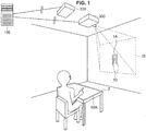
- FIG. 1 is a diagram illustrating a configuration example of the information processing system according to the embodiment of the present disclosure.
- the information processing system includes an information processing device 100, a measurement device 200, and a projection device 300.
- the information processing device 100, the measurement device 200, and the projection device 300 communicate with each other.
- the information processing device 100 controls projection of the projection device 300 using a measurement result of the measurement device 200. Specifically, the information processing device 100 recognizes a part of the body of a user serving as a manipulator from the measurement result supplied from the measurement device 200. Then, the information processing device 100 controls an aspect of the projection by the projection device 300 on the basis of a positional relation between the recognized part of the body and a region in which an input by the manipulator is recognized in a manipulation region (hereinafter also referred to as an input recognition region). For example, the information processing device 100 controls a projection position or the like of a virtual object 20 which the projection device 300 is caused to project on the basis of a position of a hand of the user measured by the measurement device 200 and a position of an input recognition region 50A. Note that the manipulation region corresponds to a measurement range of the measurement device 200. The details of the information processing device 100 will be described below.
- the measurement device 200 measures a surrounding situation of the measurement device 200. Specifically, the measurement device 200 measures a phenomenon in which a position or a state of an object near the measurement device 200, for example, a user, a manipulator, or the like, is grasped. Then, the measurement device 200 supplies information obtained through the measurement (hereinafter also referred to as measurement information) to the information processing device 100 as a measurement result.
- the measurement device 200 is a depth sensor and can measure a positional relation between a part of the body (for example, a hand) on which a marker is mounted and a nearby object (that is, positions of the part of the body and the nearby object in a 3-dimensional space) by mounting the marker on the part of the body of the user.
- the measurement information may be 3-dimensional image information.
- the measurement device 200 may be an inertial sensor mounted on the user or a ring type or wristband type wearable device that includes the inertial sensor.
- the measurement device 200 may be installed in any way as long as the manipulation region can be ensured.
- the measurement device 200 may be provided on a table of which an upper surface illustrated in FIG. 1 is the input recognition region 50A.
- the projection device 300 projects an image on the basis of instruction information of the information processing device 100. Specifically, the projection device 300 projects the image supplied from the information processing device 100 to an instructed place. For example, the projection device 300 projects the virtual object 20 to the projection region 10 illustrated in FIG. 1 as instructed by the information processing device 100. Note that in FIG. 1 , the projection device 300 is indicated as an example of a 2-dimensional (2D) projector, but the projection device 300 may be a 3D projector. In addition, an actual object may be located in the projection region 10. For example, in the example of FIG. 1 , a switch 1A is located in the projection region 10 as an actual object.
- the manipulation region including the input recognition region 50A and the projection region 10 that is, a display region to which the virtual object 20 or the like is projected are each located at different places.
- a manipulation region and a display region are coincident with each other.
- a device such as a smartphone or a tablet terminal that includes a touch screen
- a display screen corresponding to a display region and an input unit corresponding to a manipulation region are integrated.
- the GUI corresponding to a display region and a region corresponding to a manipulation region are coincident with each other. Therefore, when a manipulator enters a field of view of a user viewing a display screen, the user can confirm a manipulation performed by the user while viewing the display screen. Accordingly, the user can intuitively perform a manipulation.
- GUI graphical user interface
- the present disclosure proposes the information processing system capable of suppressing deterioration in manipulability in a case in which a display region and a manipulation region are different and the information processing device 100 that realizes the information processing system.
- FIG. 2 is a block diagram conceptually illustrating an example of a functional configuration of the information processing device 100 according to the embodiment of the present disclosure.
- the information processing device 100 includes a communication unit 102, a recognition unit 104, a distance information generation unit 106, and a control unit 108.
- the communication unit 102 communicates with an external device of the information processing device 100. Specifically, the communication unit 102 receives a measurement result from the measurement device 200 and transmits projection instruction information to the projection device 300. For example, the communication unit 102 communicates with the measurement device 200 and the projection device 300 in conformity with a wired communication scheme. Note that the communication unit 102 may communicate in conformity with a wireless communication scheme.
- the recognition unit 104 performs a recognition process on the basis of the measurement result of the measurement device 200. Specifically, the recognition unit 104 recognizes a manipulator on the basis of the measurement information received from the measurement device 200. As a manipulator, there is a part of the body of the user. For example, the recognition unit 104 recognizes a finger, a hand, or the like of the user on the basis of 3-dimensional image information obtained from the measurement device 200. Note that a manipulator recognized by the recognition unit 104 may be a manipulation device such as a pen type or a stick type manipulation device.
- the recognition unit 104 recognizes a position of the manipulator. Specifically, the recognition unit 104 recognizes the position of the manipulator in a manipulation region in which the manipulator is recognized. For example, the recognition unit 104 recognizes the position of the manipulator in a 3-dimensional space of the manipulation region on the basis of a distance between the measurement device 200 and the manipulator measured by the measurement device 200. Note that the recognition unit 104 may recognize the position of the manipulator on the basis of a size of the recognized manipulator.
- the recognition unit 104 recognizes a manipulation region. Specifically, the recognition unit 104 recognizes the manipulation region and an input recognition region included in the manipulation region on the basis of the measurement result of the measurement device 200.
- the manipulation region and the input recognition region correspond to an object, and thus the recognition unit 104 recognizes the manipulation region and the input recognition region by recognizing the object.
- the table 2 corresponds to the manipulation region and the manipulation region is a predetermined region for which the table 2 serves as a reference.
- an upper surface of the table 2 corresponds to the input recognition region 50A, and the input recognition region 50A is at least a partial region of the upper surface of the table 2.
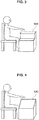
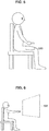
- FIGS. 3 to 6 are diagrams illustrating examples of input recognition regions in the information processing system according to the embodiment of the present disclosure.
- the input recognition region corresponds to the object, as described above.
- the input recognition region is not limited to a flat surface such as the upper surface of the table 2 illustrated in FIG. 1 and any of various shapes may be used.
- the input recognition region there is an input recognition region 50B corresponding to a surface with a stepped shape illustrated in FIG. 3 or an input recognition region 50C corresponding to an inclined surface illustrated in FIG. 4 .
- the object corresponding to the input recognition region may be a part of the body of the user.
- a part other than the knee may correspond to the input recognition region.
- the input recognition region may not correspond to an object, but may correspond to a position in a space.
- the input recognition region there is an input recognition region 50E corresponding to a predetermined position in a space which is in front of the user illustrated in FIG. 6 and is reached by a hand of the user.
- the recognition unit 104 recognizes a manipulation target of a manipulator. Specifically, the recognition unit 104 recognizes a manipulation target which is an actual object in a display region. For example, the recognition unit 104 recognizes the switch 1A which is in the projection region 10, as illustrated in FIG. 1 , as a manipulation target.
- the distance information generation unit 106 serves as an input unit and generates distance information changed in accordance with a distance between a manipulator and an input recognition region. Specifically, the distance information generation unit 106 calculates the distance between the manipulator and the input recognition region on the basis of a recognition result of the recognition unit 104. For example, the distance information generation unit 106 calculates a distance between a position of the recognized manipulator and a position of the input recognition region in a 3-dimensional space. Then, the distance information indicating the calculated distance is supplied to the control unit 108. Note that the distance information may be an index or the like corresponding to the distance between the manipulator and the input recognition region in addition to the above-described calculated value. In addition, the distance information may be information regarding a distance between the manipulator and the input recognition region in a specific direction. For example, the distance information may be information regarding a distance between the manipulator and the input recognition region in a depth direction for the user.
- the control unit 108 generally controls a process of the information processing device 100. Specifically, the control unit 108 serves as an output control unit and controls an output related to a virtual object on the basis of the distance information. More specifically the control unit 108 controls display of at least one first virtual object (hereinafter also referred to as a first feedback image or a first FB image) viewed in the display region on the basis of the distance information.
- a first feedback image or a first FB image viewed in the display region on the basis of the distance information.
- the control unit 108 controls display or non-display of the first FB image on the basis of the distance information and a threshold of the distance information. Specifically, in a case in which a value of the distance information is equal to or less than a first threshold determined in advance, the control unit 108 causes the projection device 300 to project the first FB image when the first FB image has not been projected. The control unit 108 causes the projection device 300 to continue the projection of the first FB image when the first FB image is being projected.
- the control unit 108 causes the projection device 300 to stop projecting the first FB image when the first FB image is being projected, and causes the projection device 300 not to project the first FB image when the first FB image is not projected.
- the display position of the first FB image is a position on the display region corresponding to the position of the manipulator with regard to the manipulation region.
- the control unit 108 may cause the projection device 300 to stop the projection of the first FB image.
- the second threshold is a value of the distance between the manipulator and the input recognition region which is 0 or is considered to be 0.
- the control unit 108 causes the projection device 300 to stop the projection of the first FB image. That is, when the manipulator reaches the input recognition region, the first FB image vanishes.
- display and non-display of the first FB image may be switched while the display is changed for a predetermined time.
- the control unit 108 performs control such that transparency of the first FB image decreases over time when the first FB image is projected.
- the control unit 108 performs control such that the transparency of the first FB image increases over time when the projection of the first FB image is stopped.
- the change in the display is not limited to the change in the transparency. Gradation, hue, saturation, brightness, luminance, or the like may be changed or the first FB image may be partially be deleted for the change.
- the change or non-change in the display may be switched in accordance with a setting set by the user.
- the control unit 108 controls a display aspect of the first FB image on the basis of the distance information.
- the display of the first FB image is controlled in various patterns.
- display control patterns of the first FB image will be described with reference to FIGS. 7 to 12 .
- the control unit 108 controls an aspect of the first FB image related to a display range of the first FB image on the basis of the distance information supplied from the distance information generation unit 106.
- As an aspect of the first FB image to be controlled there is a size of the first FB image.
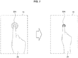
- FIG. 7 is a diagram illustrating an example of a first pattern of the display control of the first FB image in the information processing device 100 according to the embodiment of the present disclosure. For example, as illustrated in the left drawing of FIG. 7 , the virtual object 20 corresponding to a hand of the user and a first FB image 30A are projected to the projection region 10.
- the first FB image 30A becomes smaller. Conversely, when the finger of the user moves away from the input recognition region, the first FB image 30A becomes larger.
- the first FB image 30A is not limited to an image with a circular shape and may be an image with a polygonal shape or an image with any other figure.
- FIG. 8 is a diagram illustrating an example of a second pattern of the display control of the first FB image in the information processing device 100 according to the embodiment of the present disclosure.
- the virtual object 20 corresponding to the hand of the user and a first FB image 30B such as a set of objects with a particle shape are projected to the projection region 10. Then, when a finger of the user which is a manipulator comes closer to the input recognition region, as illustrated in the right drawing of FIG.
- the objects with the particle shape are collected so that the first FB image 30B is formed in a predetermined shape (for example, a circle).
- a predetermined shape for example, a circle
- the objects with the particle shape are dispersed, so that the shape of the first FB image 30B collapses.
- the degree to which the first FB image is formed is changed in accordance with the distance information.
- the shape of the first FB image may be changed from an amoeboid shape to a circular shape and vice versa on the basis of the distance information.
- the control unit 108 controls display of the first FB image with a shape corresponding to a manipulator on the basis of the distance information.
- the first FB image with the shape corresponding to the manipulator there is an image evoking the shadow of the manipulator (hereinafter also simply referred to as the shape of the manipulator).
- the control unit 108 controls depth of the shadow of the manipulator on the basis of the distance information.
- FIG. 9 is a diagram illustrating an example of a third pattern of the display control of the first FB image in the information processing device 100 according to the embodiment of the present disclosure. For example, as illustrated in the left drawing of FIG.
- the virtual object 20 corresponding to a finger of the user and a first FB image 30C such as the shadow of the virtual object 20 (that is, the shadow of a finger of the user) are projected to the projection region 10. Then, when the finger of the user which is a manipulator becomes closer to the input recognition region, as illustrated in the right drawing of FIG. 9 , the first FB image 30C becomes thicker (that is, transmittance of light decreases). Conversely, when the finger of the user becomes away from the input recognition region, the first FB image 30C becomes thin (that is, the transmittance of light increases).
- the control unit 108 controls display of the second virtual object corresponding to the manipulator (hereinafter also referred to as a manipulator image) and the first FB image may be displayed on the basis of the manipulator image.
- the manipulator image there is a generated image such as a captured image or an illustration image of a manipulation device or a part of the body of the user performing a manipulation.
- the first FB image with a shape corresponding to the manipulator is decided on the basis of the manipulator image.
- the manipulator image may be the virtual object 20 corresponding to a hand of the user illustrated in FIG. 9 and the first FB image 30C may be a virtual shadow simulated as if virtual light were radiated to the virtual object 20.
- the display of the manipulator image may be controlled in response to a manipulation of the manipulator by the user.
- the manipulator image may be moved or rotated in response to movement or rotation of the manipulator.
- the control unit 108 controls a virtual effect on the first FB image on the basis of the distance information.
- the virtual effect on the first FB image means a virtual effect that has no influence on a display range of a size, a shape, or the like of the first FB image.
- the control of the virtual effect on the first FB image there is transparency of the first FB image.
- FIG. 7 For example, when a finger of the user which is a manipulator becomes closer to the input recognition region, as illustrated in the right drawing of FIG. 7 , the transparency of the first FB image 30A becomes lower than that of the first FB image 30A illustrated in the left drawing of FIG. 7 . Conversely, when the finger of the user becomes away from the input recognition region, the transparency of the first FB image 30A increases.
- the color of the first FB image 30B is changed to a color (blue) of a cooler color system than the first FB image 30B (red) illustrated in the left drawing of FIG. 8 .
- the color of the first FB image 30B is changed to a color of a warm color system. Note that texture may be controlled instead of the color or together with the color.
- control unit 108 controls display density of the first FB image on the basis of the distance information.
- the description will be made with reference to FIG. 8 .
- parts such as dots forming the first FB image 30B are denser than parts forming the first FB image 30B illustrated in the left drawing of FIG. 8 .
- the parts forming the first FB image 30B are dispersed.
- display density of the first FB image may be changed within a fixed display range. For example, the number of parts forming the first FB image may be increased or decreased with the display range of the first FB image being fixed.
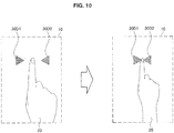
- FIG. 10 is a diagram illustrating an example of a fourth pattern of the display control of the first FB image in the information processing device 100 according to the embodiment of the present disclosure.
- the virtual object 20 corresponding to a hand of the user and the first FB images 30D1 and 30D2 are projected to the projection region 10. Then, when a finger of the user which is a manipulator becomes closer to the input recognition region, as illustrated in the right drawing of FIG.
- the first FB images 30D1 and 30D2 are closer to each other. Conversely, when the finger of the user becomes away from the input recognition region, the first FB images 30D1 and 30D2 becomes distant from each other.
- the first FB images 30D are not limited to an image with a triangular shape and may be an image with a circular shape or an image with a polygonal shape equal to or greater than a rectangular shape or a character image such as an animal or human image.
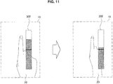
- FIG. 11 is a diagram illustrating an example of a fifth pattern of the display control of the first FB image in the information processing device 100 according to the embodiment of the present disclosure.
- the virtual object 20 corresponding to a hand of the user and a first FB image 30E indicating the value of the distance information as a length in the vertical direction are projected to the projection region 10. Then, when a finger of the user which is a manipulator becomes closer to the input recognition region, as illustrated in the right drawing of FIG.
- the length of the first FB image 30E is shortened. Conversely, when the finger of the user becomes away from the input recognition region, the length of the first FB image 30E is lengthened.
- the first FB image indicating the value of the distance information may be an image indicating a numerical value equivalent to the value of the distance information.
- the above-described second threshold may be expressed in the first FB image.
- the second threshold may be expressed as a middle line of the first FB image 30E illustrated in FIG. 11 .
- the first threshold may be expressed in the first FB image.
- control unit 108 may control a manipulator image as the first FB image. Specifically, the control unit 108 controls display of manipulator image on the basis of the distance information.
- the display control of the manipulator image may be substantially the same as a part of the display control of the above-described first FB image.
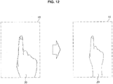
- FIG. 12 is a diagram illustrating an example of a sixth pattern of the display control of the first FB image in the information processing device 100 according to the embodiment of the present disclosure. For example, as illustrated in the left drawing of FIG. 12 , the virtual object 20 which is a manipulator image corresponding to a hand of the user is projected to the projection region 10.
- the first FB image is not separately projected.
- the contour of the virtual object 20 becomes clearer than the virtual object 20 illustrated in the left drawing of FIG. 12 .
- the contour of the virtual object 20 is blurred.
- the control unit 108 further controls display of the first FB image on the basis of information regarding a manipulation target (hereinafter also referred to as manipulation target information).
- manipulation target information there is information regarding an aspect of a manipulation target.
- the control unit 108 controls the display of the first FB image on the basis of information regarding a size or a shape of the manipulation target. Further, display control of the first FB image based on the manipulation target information will be described with reference to FIG. 13.
- FIG. 13 is a diagram illustrating an example of the display control of the first FB image based on the manipulation target information in the information processing device 100 according to the embodiment of the present disclosure.
- the control unit 108 acquires the manipulation target information before display of the first FB image starts. For example, when it is decided that the first FB image is displayed, the control unit 108 acquires information of a size, a shape, a color, or the like of a manipulation target recognized as the manipulation target information from the recognition unit 104.
- the control unit 108 decides display control of the first FB image (hereinafter also referred to as first display control) based on the distance information
- the control unit 108 decides display control of the first FB image based on the manipulation target information (hereinafter also referred to as second display control).
- the control unit 108 decides a size of the first FB image on the basis of the size of the manipulation target acquired from the recognition unit 104 in addition to the display control of the first FB image decided on the basis of the distance information.
- a size of a first FB image 30H is decided as a size including a predetermined range or more of a manipulation target 1A.
- the size of the first FB image 30H is decided to be smaller than the size of the first FB image 30H in Case 1. Note that a processing order of the first display control and the second display control may be reverse.
- a virtual effect of the first FB image may be changed instead of the change in the size of the first FB image or together with the change in the size of the first FB image in a case in which the size of the first FB image is smaller than a predetermined size.
- the control unit 108 may increase the transparency of the first FB image while reducing the first FB image to the predetermined size.
- the manipulation target in a case in which the manipulation target is a virtual object which is not an actual object, the manipulation target may be extended. For example, when a virtual object of an icon such as a magnifying glass is displayed and a manipulation of selecting the icon is recognized, the manipulation target may be extended and displayed. Thus, it is possible to prevent the first FB image from becoming small.
- the control unit 108 further controls display of a third virtual object according to a manipulation target by a manipulator (hereinafter also referred to as a second feedback image or a second FB image) on the basis of the recognition of an input by the manipulator. Specifically, when the value of the distance information reaches a second threshold or less (that is, the manipulator reaches the input recognition region), the control unit 108 performs a process corresponding to an input by the manipulator assuming that the input is performed by the manipulator. In addition, when the value of the distance information reaches a second threshold or less, the control unit 108 causes the projection device 300 to project the second FB image in accordance with the manipulation target. Further, the display control of the second FB image will be described with reference to FIG. 14.
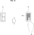
- FIG. 14 is a diagram illustrating an example of the display control of the second FB image in the information processing device 100 according to the embodiment of the present disclosure.
- the control unit 108 determines whether the value of the distance information reaches the second threshold or less. For example, the control unit 108 periodically determines whether the value of the distance information reaches the second threshold or less while the first FB image is projected.
- the control unit 108 When it is determined that the value of the distance information reaches the second threshold or less, the control unit 108 performs a process on the manipulation target corresponding to the input by the manipulator. For example, when it is determined that the value of the distance information reaches the second threshold or less, the control unit 108 switches a switch 1B illustrated in FIG. 14 between ON and OFF.
- ON or OFF of activation, a function, or the like of a device connected to the switch 1B is switched without controlling the switch 1B. Note that the switch 1B may be controlled such that ON or OFF of the switch 1B may be actually switched.
- control unit 108 causes the projection device 300 to project the second FB image.
- the control unit 108 causes the projection device 300 to project a second FB image 40A illustrated in the right drawing of FIG. 14 in accordance with a position and a shape of the switch 1B.
- recognition of the input by the manipulator may be realized using information other than the distance information.
- the control unit 108 controls display of the second FB image on the basis of a pressure on the input recognition region from the manipulator.
- the control unit 108 controls display or non-display of the second FB image in accordance with information regarding whether there is a pressure supplied from a pressure sensor or the like installed in the input recognition region as the measurement device 200.
- a display aspect of the second FB image may be controlled in accordance with information regarding the degree of the pressure supplied from the pressure sensor.
- control unit 108 may control the display of the second FB image on the basis of a change in the shape of the manipulator.
- the control unit 108 controls display or non-display of the second FB image in accordance with a change or non-change in the shape of a finger of the user recognized by the recognition unit 104 (for example, a change or the like to a shape applying a force).
- the display aspect of the second FB image may be controlled in accordance with the degree of change in the shape.
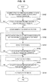
- FIG. 15 is a flowchart conceptually illustrating an example of a process of the information processing device 100 according to the embodiment of the present disclosure.
- the information processing device 100 acquires the distance information regarding the distance between the position of the manipulator and the input recognition region (step S402). Specifically, the recognition unit 104 recognizes the manipulator and the input recognition region on the basis of a measurement result of the measurement device 200 and the distance information generation unit 106 generates the distance information regarding the distance between the recognized manipulator and input recognition region.
- the information processing device 100 determines whether the value of the distance information is equal to or less than the first threshold (step S404). Specifically, the control unit 108 determines whether the value of the generated distance information is equal to or less than the first threshold.
- the information processing device 100 acquires the manipulation target information (step S406). Specifically, when it is determined that the value of the distance information is equal to or less than the first threshold, the recognition unit 104 recognizes the aspect of the manipulation target and supplies the aspect of the manipulation target to the control unit 108.
- the information processing device 100 decides control content of the first FB image on the basis of the distance information and the manipulation target information (step S408). Specifically, the control unit 108 decides the first display control on the first FB image on the basis of the distance information and further decides the second display control on the basis of the aspect of the manipulation target recognized by the recognition unit 104.
- the information processing device 100 causes a display device to display the first FB image (step S410).
- the control unit 108 causes the projection device 300 to project the first FB image by performing the decided first display control and second display control.
- the information processing device 100 determines whether the value of the distance information is equal to or less than the second threshold (step S412). Specifically, the control unit 108 determines whether the value of the distance information is equal to or less than the second threshold after the projection of the first FB image.
- the information processing device 100 causes the display device to display the second FB image (step S414).
- the control unit 108 causes the projection device 300 to project the second FB image.
- the information processing device 100 determines whether the value of the distance information is greater than the second threshold (step S416). Specifically, the control unit 108 determines whether the value of the distance information is greater than the second threshold after the projection of the second FB image.
- the information processing device 100 stops the display of the FB images (step S418). Specifically, when it is determined that the value of the distance information is greater than the second threshold, the control unit 108 causes the projection device 300 to stop the projection of the first and second FB images. Note that when the second FB image is projected in step S414, the control unit 108 may cause the projection device 300 to stop the projection of the first FB image.
- the information processing device 100 controls an output related to the virtual object on the basis of the distance information changed in accordance with a distance between a manipulator recognized in a different manipulation region from a display region in which the virtual object is viewed and an input recognition region in which an input by the manipulator in the manipulation region is recognized.
- a reference for a distance between the position of a manipulator and a position at which an input of a manipulation by the manipulator is recognized (hereinafter also referred to as a sense of distance related to a manipulation) can be presented to a user. Therefore, the user can intuitively manipulate the manipulator while viewing the display region. Accordingly, it is possible to suppress deterioration in manipulability in a case in which the display region and the manipulation region are different.
- the information processing device 100 is beneficial.
- an intuitive manipulation is possible, it is possible to accelerate a skill of an input manipulation.
- the output includes display of at least one first virtual object. Therefore, it is possible to enable the user viewing the display region to ascertain the sense of distance related to a manipulation. In addition, since the sense of vision facilitates understanding of more information at a time than other senses, the sense of distance is enabled to grasp the sense of distance related to a manipulation at a relatively short time.
- the output may be an output other than the display of the first FB image.
- the output may be a sound or a tactile vibration.
- a sound or a tactile vibration For example, when the value of the distance information is equal to or less than the first threshold, occurrence of a sound such as a mechanical sound or a voice or a tactile vibration is started.
- the sound or the tactile vibration is stopped.
- kinds of sounds or tactile vibrations may be switched instead of stopping the sound or the tactile vibration.
- a sound or a tactile vibration may be used together with the display of the first FB image.
- a sound or a tactile vibration based on the distance information may be output instead of or together with the display of the first FB image.
- the user is enabled to grasp the sense of distance related to a manipulation.
- the information processing device 100 controls an aspect of the first virtual object related to a display range of the first virtual object on the basis of the distance information. Therefore, when the display range of the first FB image is changed, the user is enabled to be aware of a change in the sense of distance related to a manipulation. Accordingly, it is possible to promote an improvement in precision of the manipulation by the user.
- the aspect of the first virtual object includes a size or a shape of the first virtual object. Therefore, by changing the size or the shape of the first FB image in accordance with the distance information, the user is enabled to intuitively understand the sense of distance related to a manipulation.
- the information processing device 100 controls a positional relation between the plurality of first virtual objects on the basis of the distance information. Therefore, for example, by changing the distances of the plurality of first FB images in accordance with the distance information, the user is enabled to understand the sense of distance related to a manipulation intuitively and more accurately.
- the information processing device 100 controls a virtual effect on the first virtual object on the basis of the distance information. Therefore, by using the virtual effect of not changing the display range of the first FB image, the sense of distance related to a manipulation can be presented to the user even in a case in which the sufficient display range may not be ensured in the display of the first FB image. Accordingly, visibility of the display region and conveyance of the sense of distance related to the manipulation can be caused to be compatible.
- control of the virtual effect on the first virtual object includes control of transparency, gradation, or a color of the first virtual object. Therefore, the user is enabled to effectively recognize the sense of distance related to a manipulation without changing the display range.
- the information processing device 100 controls display density of the first virtual object on the basis of the distance information. Therefore, by controlling magnitude of the display density in accordance with the distance information, the user is enabled to intuitively understand the sense of distance related to a manipulation.
- the first virtual object includes a virtual object with a shape corresponding to the manipulator. Therefore, the user is enabled to easily understand that the first FB image is related to the manipulator manipulated by the user.
- the first virtual object includes a virtual object expressing a value of the distance information. Therefore, the sense of distance related to an accurate manipulation by the user can be presented to the user. Accordingly, it is possible to further accelerate a skill of an input manipulation.
- the information processing device 100 further controls display of the second virtual object corresponding to the manipulator, and the first virtual object includes a virtual object displayed on the basis of the second virtual object. Therefore, by displaying the manipulator image to correspond to the manipulator, the user is enabled to easily grasp a place corresponding to the manipulation by the user in the display region. Further, by displaying the first FB image on the basis of the manipulator image, it is possible to alleviate the sense of discomfort of the user to the first FB image. Accordingly, the user can naturally understand the sense of distance related to the manipulation.
- the display region includes a region including a manipulation target by the manipulator, and the information processing device 100 further controls the display of the first virtual object on the basis of information regarding the manipulation target. Therefore, for example, by controlling the display of the first FB image in accordance with the aspect of the manipulation target, it is possible to prevent one of visibility of the first FB image and visibility of the manipulation target from deteriorating one-sidedly. Accordingly, maintenance or improvement in manipulability of the manipulation target and grasping of the sense of distance related to a manipulation can be caused to be compatible.
- the information processing device 100 controls display or non-display of the first virtual object on the basis of a threshold of the distance information. Therefore, only in a situation in which the user is estimated to desire the sense of distance related to the manipulation, the first FB image can be caused to be displayed. Accordingly, it is possible to present the user with the sense of distance related to the manipulation while suppressing deterioration in visibility of the display region.
- the information processing device 100 controls display of a third virtual object in accordance with a manipulation target by the manipulator on a basis of recognition of an input by the manipulator. Therefore, it is possible to present the user with the fact that an input is received. Accordingly, the user can move to a subsequent manipulation or stop the manipulation, and thus it is possible to improve usability.
- the first FB image may be displayed without displaying the manipulator image.
- the control unit 108 causes only the first FB image to be displayed in the display region.
- display control patterns of the first FB images according to the modification example will be described with reference to FIGS. 16 to 20 . Note that patterns of the display control which are substantially the same as the first to sixth patterns of the above-described display control will be described in brief and patterns of other display control will be described in detail.
- the control unit 108 controls an aspect and a visual effect of the first FB image related to the display range of the first FB image on the basis of the distance information. Specifically, the size of the first FB image and transparency of the first FB image are controlled.
- FIG. 16 is a diagram illustrating an example of a seventh pattern of the display control of the first FB image in the information processing device 100 according to the first modification example of the embodiment of the present disclosure. For example, as illustrated in the left drawing of FIG. 16 , only the first FB image 30F is projected to the projection region 10 without projecting the virtual object 20 corresponding to a hand of the user.
- the first FB image 30F has two parts of an outer circle and an inner circle.
- the outer circle of the first FB image 30F becomes smaller and the transparency of the inner circle decreases. Conversely, when the finger of the user becomes away from the input recognition region, the outer circle of the first FB image 30F becomes larger and the transparency of the inner circle increases.
- FIG. 17 is a diagram illustrating an example of an eighth pattern of the display control of the first FB image in the information processing device 100 according to the first modification example of the embodiment of the present disclosure.
- a first FB image 30B such as a set of objects with a particle shape is projected to the projection region 10 without projecting the virtual object 20 corresponding to a hand of the user.
- the objects with the particle shape are collected so that the first FB image 30B is formed in a predetermined shape (for example, a circle).
- FIG. 18 is a diagram illustrating an example of a ninth pattern of the display control of the first FB image in the information processing device 100 according to the first modification example of the embodiment of the present disclosure.
- a first FB image 30C such as the shadow of a hand of the user is projected to the projection region 10 without projecting the virtual object 20 corresponding to the hand of the user.
- the first FB image 30C becomes thicker (that is, transmittance of light decreases).
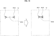
- FIG. 19 is a diagram illustrating an example of a tenth pattern of the display control of the first FB image in the information processing device 100 according to the first modification example of the embodiment of the present disclosure.
- FIG. 19 only first FB image 30G1 and 30G2 and a streak image 30G3 connecting the first FB images 30G1 and 30G2 are projected to the projection region 10 without projecting the virtual object 20 corresponding to a hand of the user. Then, when a finger of the user which is a manipulator becomes closer to the input recognition region, as illustrated in the right drawing of FIG. 19 , the first FB images 30G1 and 30G2 become closer and the first FB image 30G3 is shortened.
- FIG. 20 is a diagram illustrating an example of an eleventh pattern of the display control of the first FB image in the information processing device 100 according to the first modification example of the embodiment of the present disclosure.
- a first FB image 30E indicating the value of the distance information as a length in the vertical direction is projected to the projection region 10 without projecting the virtual object 20 corresponding to a hand of the user.
- the length of the first FB image 30E is shortened.
- the information processing device 100 causes the display device to display the first FB image without displaying the manipulator image. Therefore, it is possible to improve the visibility of the first FB image. In addition, in a case in which the manipulation target is in the display region, it is possible to also improve the visibility of the manipulation target.
- the information processing device 100 may control the display of the first FB image on the basis of a position of manipulation target.
- the control unit 108 causes the display device to display the first FB image, eluding the manipulation target.
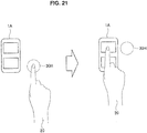
- FIG. 21 is a diagram illustrating an example of display control of the first FB image based on manipulation target information in the information processing device 100 according to the second modification example of the embodiment of the present disclosure.
- the control unit 108 causes the display device to display the first FB image when the value of the distance information is equal to or less than the first threshold. For example, as illustrated in the left drawing of FIG. 21 , the first FB image 30H and the virtual object 20 are projected.
- the control unit 108 causes the first FB image to be moved in accordance with movement of a manipulator.
- the control unit 108 causes the projection device 300 to change a projection position of the first FB image 30H to a position on the display region in accordance with the movement of the finger of the user.
- the virtual object 20 is also caused to be moved similarly to the first FB image 30H.
- the control unit 108 decides the position of the first FB image to a position separate from the manipulation target.
- the movement destination of the first FB image in accordance with the movement of the manipulator is the switch 1A which is a manipulation target. Therefore, the control unit 108 decides the movement destination of the first FB image to a position which is adjacent to the switch 1A and does not overlap the switch 1A, as illustrated in the right drawing of FIG. 21 .
- control unit 108 decides a change designation of the movement destination of the first FB image on the basis of the position of the virtual object 20. For example the control unit 108 decides a position which is within a predetermined range from the virtual object 20 and does not overlap the switch 1A as the movement destination of the first FB image.
- the information processing device 100 controls display of the first FB image on the basis of the position of the manipulation target. Therefore, the first FB image can be displayed at the position at which the manipulation target does not overlap the first FB image. Accordingly, the visibility of the first FB image and the visibility of the manipulation target can be caused to be compatible and it is possible to more reliably suppress the deterioration in the manipulability.
- the information processing device 100 may select the first FB image on the basis of a color, a shape, or a texture of the manipulation target or the display region.
- the control unit 108 causes the projection device 300 to project the first FB image with a color, a shape, or a texture which is not the same as or analogous to the manipulation target or the display region. In this case, it is possible to ensure the visibility of the first FB image.
- the number of manipulators for manipulating a manipulation target may be plural.
- the control unit 108 controls the display of the first FB image in accordance with the number of manipulators.
- the control unit 108 causes the display device to display the number of first FB images corresponding to the number of manipulators.
- FIG. 22 is a diagram illustrating a display example of the plurality of first FB images in the information processing device 100 according to the third modification example of the embodiment of the present disclosure.
- the control unit 108 causes the display device to display the first FB image with regard to each of a plurality of manipulators recognized by the recognition unit 104. For example, when the recognition unit 104 recognizes two fingers (the thumb and the forefinger) illustrated in FIG. 22 and the value of the distance information related to the two fingers is equal to or less than the first threshold, the control unit 108 causes the projection device 300 to project each first FB image 30A with regard to each of the two fingers.
- the first FB image may be displayed with regard to only some of the manipulators, the first FB image may be displayed with regard to all the plurality of manipulators, or the first FB image may not be displayed with regard to all the plurality of manipulators.
- any of the above-described first FB mages in addition to the first FB images 30A may be projected.
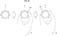
- control unit 108 may control the display of the second FB image on the basis of manipulations on the plurality of manipulators. Specifically, when inputs by the plurality of manipulators are recognized, the control unit 108 causes the display device to display the second FB image and controls an aspect of the second FB image in response to continuously input manipulations. Display control of the second FB image based on manipulations on the plurality of manipulators will be described in detail with reference to FIG. 23.
- FIG. 23 is a diagram illustrating an example of display control of the second FB image in the information processing device 100 according to the third modification example of the embodiment of the present disclosure.
- the control unit 108 causes the display device to display the second FB image.
- a thumb and a forefinger of a user are manipulators and each value of the distance information related to the manipulators reaches the second threshold or less, a second FB image 40B with a triangular shape illustrated in FIG. 23 is projected to a predetermined position of a scale of a dial 1D which is a manipulation target.
- the control unit 108 controls a display aspect of the second FB image on the basis of a manipulation performed when the value of the distance information is equal to or less than the second threshold. For example, when a manipulation of rotating a hand is performed with two fingers, which are manipulators, being fixed with respect to the hand, as illustrated in the right drawing of FIG. 23 , the position of the second FB image 40B is caused to be rotationally moved centering the dial 1D in accordance with a rotation angle of the hand.
- the control unit 108 may cause the dial 1D to be actually rotated.
- the control unit 108 causes a device including the dial 1D to rotate the dial 1D by transmitting an instruction to rotate the dial 1D.
- the information processing device 100 controls the display of the first FB image in accordance with the number of manipulators. Therefore, in a complicated manipulation using a plurality of manipulators, the sense of distance related to a manipulation can be presented to the user. Accordingly, it is possible to improve manipulability in the complicated manipulation.
- the information processing device 100 controls the display of the second FB image on the basis of the manipulations by the plurality of manipulators. Therefore, the user can manipulate the manipulation target in which a manipulation more complicated than a manipulation by a single manipulator is requested. Accordingly, it is possible to extend an application range of the information processing device 100.
- the information processing device 100 controls display of the first FB image on the basis of information regarding a user manipulating a manipulator (hereinafter also referred to as user information).
- user information there is information regarding of a skill level of the manipulation by the user (hereinafter also referred to as skill level information).
- the recognition unit 104 identifies the user performing a manipulation and the control unit 108 acquires the skill level information of the identified user. Then, the control unit 108 controls the display of the first FB image on the basis of the skill level information.
- FIG. 24 is a diagram illustrating an example of display control of the first FB image in the information processing device 100 according to the fourth modification example of the embodiment of the present disclosure.
- the recognition unit 104 recognizes the user performing the manipulation in the manipulation region. For example, the recognition unit 104 acquires image information in which the user performing the manipulation in the manipulation region is shown from the measurement device 200 via the communication unit 102. Then, the recognition unit 104 recognizes the user using a face recognition technology on the basis of the acquired image information. Note that the method of recognizing the user is not limited thereto and any other method may be used.
- control unit 108 acquires the skill level information of the recognized user. For example, the control unit 108 calculates the skill level of the manipulation from a manipulation history of the user recognized by the recognition unit 104. Note that the skill level information may be stored in the information processing device 100 or may be stored in an external device.
- the control unit 108 determines an aspect of the first FB image on the basis of the acquired skill level information. Specifically, the control unit 108 causes the display device to display the first FB image with a size in accordance with the skill level information. For example, the control unit 108 causes the projection device 300 to project the larger first FB image as the calculated or acquired skill level is higher. As illustrated in FIG. 24 , a first FB image 30H after one week passes after use start of the information processing device 100 is projected smaller than the first FB image 30H after 3 days passes from the use start. This is because the skill level of a manipulation is considered to be higher as a time elapsed from the use start is longer. Note that an aspect in accordance with the skill level may be the shape, the display position, the virtual effect, or the like described above in addition to the size.
- the control unit 108 controls the aspect of the first FB image depending on an individual user identified by the recognition unit 104.
- there is attribute information of the user For example, the control unit 108 controls the aspect of the first FB image depending on an age, a sex, an address, nationality, or the like of the user recognized by the recognition unit 104.
- the information processing device 100 further controls the display of the first FB image on the basis of information related to the user manipulating the manipulator.
- a manipulation behavior generally differs for each user for which a skill level, a nature, or the like of the user is a factor. Therefore, as in the modification example, by causing the first FB image to be changed in accordance with the user, it is possible to supply the sense of distance related to a manipulation appropriate for the individual user.
- the first threshold of the distance information may be variable.
- the control unit 108 controls the first threshold on the basis of the distance information. For example, in a case in which a difference between the value of the distance information and the first threshold is within a predetermined range, the control unit 108 changes the first threshold to a value at which the difference between the value of the distance information and the first threshold stretches.
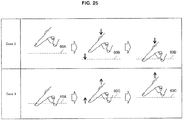
- FIG. 25 is a diagram illustrating an example of control of the first threshold of the distance information in the information processing device 100 according to the fifth modification example of the embodiment of the present disclosure.
- control of the first threshold before the display of the first FB image will be described with reference to Case 3 of FIG. 25 .
- the control unit 108 lowers the first threshold when the value of the distance information reaches a value within the predetermined range with regard to the first threshold. For example, when the finger of the user which is a manipulator reaches a predetermined height higher than a first threshold value 60A, the first threshold is lowered from the first threshold 60A to 60B.
- the control unit 108 causes the display device to display the first FB image.
- the first threshold is lowered to the first threshold 60B and the finger of the user is subsequently further lowered to the first threshold 60B or less
- an input by the finger of the user is recognized. That is, the first FB image is projected to a projection region.
- control of the first threshold after the display of the first FB image will be described with reference to Case 4 of FIG. 25 will be described.
- the control unit 108 raises the first threshold when the value of the distance information reaches the predetermined range with regard to the first threshold. For example, when the finger of the user which is a manipulator reaches a predetermined height lower than a first threshold value 60A, the first threshold is raised from the first threshold 60A to 60C.
- the control unit 108 causes the display device to stop the display of the first FB image. For example, when the first threshold is raised to the first threshold 60C and the finger of the user is subsequently further raised to the first threshold 60C, the projection of the first FB image is stopped.
- the control unit 108 may control the first threshold on the basis of information regarding the manipulator (hereinafter also referred to as manipulator information).
- manipulator information there is information regarding an aspect of a manipulator.
- the control unit 108 controls the first threshold on the basis of a size of the manipulator. For example, the first threshold is set so that the first threshold is higher as the finger of the user is larger.
- the control unit 108 may control the first threshold on the basis of a speed of movement of the manipulator. For example, the first threshold is set so that the first threshold is higher as a movement speed or acceleration of the finger of the user is faster.
- control unit 108 may control the first threshold on the basis of the user information. Specifically, the control unit 108 may control the first threshold on the basis of the attribute information of the user.
- attribute information of the user there is information regarding an age, a sex, handedness, or the like of the user.
- the first threshold is set so that the first threshold is higher as the age of the user is higher.
- FIG. 26 is a flowchart conceptually illustrating an example of a process to which the control of the first threshold in which manipulator information or user information is used is added in the information processing device 100 according to the fifth modification example of the embodiment of the present disclosure.
- the information processing device 100 acquires the manipulator information or the user information (step S502). Specifically, the recognition unit 104 recognizes the manipulator and an aspect of the manipulator which is in the manipulation region and supplies information regarding the aspect of the recognized manipulator to the control unit 108. In addition, the recognition unit 104 recognizes a user which is in the manipulation region using a face recognition technology or the like and supplies identification information or the like of the recognized user to the control unit 108.
- the information processing device 100 decides the first threshold on the basis of the manipulator information or the user information (step S504). Specifically, the control unit 108 changes the first threshold from a reference value on the basis of information regarding the acquired aspect of the manipulator. In addition, the control unit 108 changes the first threshold from the reference value on the basis of the acquired identification information of the user and the attribute information of the user to be acquired. Of course, the first threshold may not be changed as a result in some cases.
- steps S506 to S522) after the first threshold is decided are substantially the same as the processes described with reference to FIG. 15 , the description thereof will be omitted.
- the plurality of first thresholds of the distance information may be provided.
- the control unit 108 selects the first threshold to be used for a display control process for the first FB image from the plurality of first threshold values on the basis of the manipulator information or the user information. For example, in a case in which a speed of movement of the manipulator is equal to or greater than a predetermined value, the control unit 108 selects the first threshold higher than the reference value (that is, a distance between the manipulator and the input recognition region is long). Then, when the value of the distance information reaches the selected first threshold or less, the control unit 108 causes the projection device 300 to project the first FB image.
- the information processing device 100 controls the first threshold on the basis of the distance information. Therefore, by changing the firs threshold depending on a situation, it is possible to optimize a display time of the first FB image. Accordingly, the user is enabled to grasp the sense of distance related to the manipulation more reliably and visibility of the display region can be prevented from deteriorating due to the display of the first FB image.
- the information processing device 100 controls the first threshold on the basis of the information regarding the manipulator.
- the manipulator is larger and the movement of the manipulator is faster, a time taken until the manipulator reaches the input recognition region is shorter, and thus the display time of the first FB image is shorter. Accordingly, by setting the first threshold in accordance with the manipulator, it is possible to optimize the display time of the first FB image. Thus, the user is enabled to reliably grasp the sense of distance related to the manipulation.
- the information processing device 100 controls the first threshold on the basis of information regarding the user.
- a time taken for the user to grasp the sense of distance related to the manipulation generally differs. For example, as the age of the user is higher, a time take to grasp the sense of distance related to the manipulation is longer. Accordingly, by setting the first threshold value in accordance with the user, it is possible to optimize the display time of the first FB image for the user. Thus, the user is enabled to reliably grasp the sense of distance related to the manipulation.
- the information processing device 100 selects the first threshold to be used for the display control of the first FB image from the plurality of first thresholds. Therefore, the process of controlling the first threshold value can be further simplified than in a case in which the single first threshold varies. Accordingly, it is possible to accelerate the process of controlling the first threshold, and thus it is possible to suppress a time lag between the manipulation by the user and the display of the first FB image.
- the number of users performing manipulations may be plural.
- the control unit 108 performs display control of the first FB image based on distance information on each of manipulators manipulated by the plurality of users.
- the recognition unit 104 recognizes the plurality of users performing manipulations in manipulation regions and recognizes each manipulator manipulated by each user.
- the distance information generation unit 106 generates distance information of each of the recognized manipulators.
- the control unit 108 causes the projection device 300 to project each first FB image on the basis of whether the value of the generated distance information is equal to or greater than the first threshold with regard to each manipulator.
- control unit 108 causes the display device to display each first FB image and each manipulator image in accordance with each manipulator related to the user. Specifically, each first FB image in an identification aspect in accordance with each user is displayed. For example, the first FB image with a color, a pattern, a shape, or a figure in accordance with each user is projected. Further, the identification aspect of the first FB image may be decided on the basis of information regarding the recognized user. For example, the color of the first FB image may be decided from a color or the like of a cloth which the recognized user wears.
- the manipulator image with the identification aspect in accordance with each user is displayed.
- the control unit 108 acquires an image of each of the manipulators related to the plurality of users from a captured image and causes the projection device 300 to project each of the acquired images.
- the manipulator image may be a generated image such as an illustration image, as described above. In this case, the generation image corresponding to each user is used.
- the first FB image in accordance with the manipulator related to the user may be displayed.
- the information processing device 100 performs the display control of the first FB image based on the distance information on each of the manipulators manipulated by the plurality of users. Therefore, even in a case in which the plurality of users simultaneously perform manipulations in the manipulation regions provided in different places from the display region, the deterioration in the manipulability of each user can be prevented from deteriorating by presenting the sense of distance related to the manipulation to each user. In addition, by displaying the first FB image so that the first FB image can be individually identified by each user, each user can perform the manipulation without being confused.
- the information processing devices 100 according to an embodiment of the present disclosure have been described above.
- the processing performed by the information processing device 100 is achieved by cooperatively operating software and hardware of the information processing device 100 described below.
- FIG. 27 is an explanatory diagram illustrating a hardware configuration of the information processing device 100 according to an embodiment of the present disclosure.
- the information processing device 100 includes a processor 132, a memory 134, a bridge 136, a bus 138, an interface 140, an input device 142, an output device 144, a storage device 146, a drive 148, a connection port 150, and a communication device 152.
- the processor 132 functions as an arithmetic processing device, and achieves the functions of the speech recognition unit 104, a distance information generation unit 106, and the control unit 108 in the information processing device 100 by cooperatively operating with various programs.
- the processor 132 causes various logical functions of the information processing device 100 to operate, by using a control circuit to execute programs stored in the memory 134 or another storage medium.
- the processor 132 may be a central processing unit (CPU), a graphics processing unit (GPU), a digital signal processor (DSP), or a system on chip (SoC).
- the memory 134 stores a program, a calculation parameter, and the like used by the processor 132.
- the memory 134 includes a random access memory (RAM), and transiently stores programs used for executing the processor 132, parameters or the like that change as appropriate when executing the processor 132.
- the memory 134 includes a read only memory (ROM), and functions as the storage unit by using the RAM and the ROM. Note that, an external storage device may be used as a part of the memory 134 via the connection port 150 or the communication device 152.
- processor 132 and the memory 134 are connected to each other via an internal bus including a CPU bus or the like.
- the bridge 136 connects buses. Specifically, the bridge 136 connects the internal bus and the bus 138.
- the internal bus is connected to the processor 132 and the memory 134.
- the bus 138 is connected to the interface 140.
- the input device 142 is used by a user for operating the information processing device 100 or inputting information to the information processing device 100.
- the input device 142 includes an input means to which the user inputs information, and an input control circuit that generates an input signal on the basis of the user input and outputs the generated input signal to the processor 132.
- the input means may be a mouse, a keyboard, a touchscreen, a switch, a lever, a microphone, or the like.
- the display device 144 is used to notify a user of information.
- the output device 144 may be a device such as a liquid crystal display (LCD) device, an organic light emitting diode (OLED) device, a projector, a speaker, or a headphone, or may be a module configured to output information to such a device.
- LCD liquid crystal display
- OLED organic light emitting diode
- the input device 142 or the output device 144 may include an input/output device.
- the input/output device may be a touchscreen.
- the storage device 146 is a data storage device.
- the storage device 146 may include a storage medium, a recording device that records data on the storage medium, a reading device that reads data from the storage medium, a deletion device that deletes data recorded on the storage medium, and the like.
- the storage device 146 stores various kinds of data or a program to be executed by the CPU 132.
- the drive 148 is a reader/writer for a storage medium, and is incorporated in or externally attached to the information processing device 100.
- the drive 148 reads information stored in a removable storage medium that is mounted, such as a magnetic disk, an optical disc, a magneto-optical disk, or semiconductor memory, and outputs the information to the memory 134.
- the drive 148 is also capable of writing information to the removable storage medium.
- connection port 150 is a port used to directly connect apparatuses to the information processing device 100.
- the connection port 150 may be a USB (Universal Serial Bus) port, an IEEE1394 port, or a SCSI (Small Computer System Interface) port.
- the connection port 150 may be an RS-232C port, an optical audio terminal, an HDMI (registered trademark) (High-Definition Multimedia Interface) port, or the like. Data may be exchanged between the information processing device 100 and an external apparatus by connecting the external apparatus to the connection port 150.
- the communication device 152 mediates communication between the information processing device 100 and an external device, and functions as the communication unit 102. Specifically, the communication device 152 establishes communication in accordance with a wireless communication scheme or a wired communication scheme. For example, the communication device 152 establishes wireless communication in accordance with a cellular communication scheme such as Wideband Code Division Multiple Access (W-CDMA) (registered trademark), WiMAX (registered trademark), Long-Term Evolution (LTE), or LTE-A.
- W-CDMA Wideband Code Division Multiple Access
- WiMAX registered trademark
- LTE Long-Term Evolution
- LTE-A Long-Term Evolution
- the communication device 152 may establish wireless communication in accordance with any wireless communication scheme like a short-range wireless communication such as Bluetooth (registered trademark), near-field communication (NFC), wireless USB, or TransferJet (registered trademark), or a wireless local area network (LAN) such as Wi-Fi (registered trademark).
- a short-range wireless communication such as Bluetooth (registered trademark), near-field communication (NFC), wireless USB, or TransferJet (registered trademark), or a wireless local area network (LAN) such as Wi-Fi (registered trademark).
- LAN wireless local area network
- Wi-Fi registered trademark
- the communication device 152 may establish wired communication such as signal line communication or wired LAN communication.
- the information processing device 100 does not have to include a part of the structural elements described with reference to FIG. 27 .
- the information processing device 100 may include any additional structural element.
- the reference of a distance between the position of a manipulator and a position at which an input of a manipulation by the manipulator is recognized (hereinafter also referred to a sense of distance related to the manipulation) can be presented to a user. Therefore, the user can intuitively manipulate the manipulator while viewing the display region. Accordingly, it is possible to suppress deterioration in manipulability in a case in which the display region and the manipulation region are different.
- the information processing device 100 is beneficial.
- an intuitive manipulation is possible, it is possible to accelerate a skill of an input manipulation.
- the distance information is information regarding a distance in the depth direction to the user
- the present technology is not limited to the example.
- the distance information may be one direction among the vertical and horizontal directions to the user or another specific direction.
- the measurement device 200 may be a visible-light imaging device, a laser ranging sensor, an ultrasonic sensor, or the like.
- the virtual object may be displayed by another display device in which a manipulation region and a display region are different.
- the virtual object may be displayed by a head-up display (HUD) in which light of an external world image is penetrated and an image is displayed on a display unit or image light related to an image is projected to the eyes of a user, a head mount display (HMD) in which a captured external world image and an image are displayed, or the like.
- HUD head-up display
- HMD head mount display
- the manipulation region and the input recognition region may be acquired in accordance with another method.
- information such as positions, areas, or the like of the manipulation region and the input recognition region may be stored in advance in the information processing device 100 or may be acquired from an external device through communication.
- the manipulation region and the input recognition region may be fixed.
- the information processing system may be a client-server type of system or a cloud service type of system.
- the information processing device 100 may be a server installed in a different place from the places in which the measurement device 200 and the projection device 300 are installed.
- a computer program for causing hardware built in the information processing device 100 to exhibit functions equivalent to those of the above-described respective logical elements of the information processing device 100 can also be produced.
- a storage medium in which the computer program is stored is also provided.
- present technology may also be configured as below.
Landscapes
- Engineering & Computer Science (AREA)
- Theoretical Computer Science (AREA)
- General Engineering & Computer Science (AREA)
- Human Computer Interaction (AREA)
- Physics & Mathematics (AREA)
- General Physics & Mathematics (AREA)
- Multimedia (AREA)
- User Interface Of Digital Computer (AREA)
Applications Claiming Priority (2)
| Application Number | Priority Date | Filing Date | Title |
|---|---|---|---|
| JP2016108409 | 2016-05-31 | ||
| PCT/JP2017/014910 WO2017208637A1 (fr) | 2016-05-31 | 2017-04-12 | Dispositif de traitement d'informations, procédé de traitement d'informations et programme |
Publications (2)
| Publication Number | Publication Date |
|---|---|
| EP3467620A1 true EP3467620A1 (fr) | 2019-04-10 |
| EP3467620A4 EP3467620A4 (fr) | 2019-05-22 |
Family
ID=60479477
Family Applications (1)
| Application Number | Title | Priority Date | Filing Date |
|---|---|---|---|
| EP17806197.4A Ceased EP3467620A4 (fr) | 2016-05-31 | 2017-04-12 | Dispositif de traitement d'informations, procédé de traitement d'informations et programme |
Country Status (3)
| Country | Link |
|---|---|
| US (1) | US20200319834A1 (fr) |
| EP (1) | EP3467620A4 (fr) |
| WO (1) | WO2017208637A1 (fr) |
Families Citing this family (6)
| Publication number | Priority date | Publication date | Assignee | Title |
|---|---|---|---|---|
| DK180470B1 (en) | 2017-08-31 | 2021-05-06 | Apple Inc | Systems, procedures, and graphical user interfaces for interacting with augmented and virtual reality environments |
| JP6745852B2 (ja) * | 2018-01-24 | 2020-08-26 | アップル インコーポレイテッドApple Inc. | 3dモデルのシステム全体の挙動のためのデバイス、方法、及びグラフィカルユーザーインターフェース |
| DK201870349A1 (en) | 2018-01-24 | 2019-10-23 | Apple Inc. | Devices, Methods, and Graphical User Interfaces for System-Wide Behavior for 3D Models |
| KR102666508B1 (ko) * | 2018-01-24 | 2024-05-20 | 애플 인크. | 3d 모델들에 대한 시스템 전체 거동을 위한 디바이스들, 방법들, 및 그래픽 사용자 인터페이스들 |
| JP2020042369A (ja) * | 2018-09-06 | 2020-03-19 | ソニー株式会社 | 情報処理装置、情報処理方法及び記録媒体 |
| JP7651874B2 (ja) * | 2021-02-18 | 2025-03-27 | オムロン株式会社 | 非接触入力支援装置、非接触入力支援方法、および、非接触入力支援プログラム |
Family Cites Families (7)
| Publication number | Priority date | Publication date | Assignee | Title |
|---|---|---|---|---|
| JP5114795B2 (ja) * | 2010-01-29 | 2013-01-09 | 島根県 | 画像認識装置および操作判定方法並びにプログラム |
| JP4900741B2 (ja) * | 2010-01-29 | 2012-03-21 | 島根県 | 画像認識装置および操作判定方法並びにプログラム |
| US9104239B2 (en) * | 2011-03-09 | 2015-08-11 | Lg Electronics Inc. | Display device and method for controlling gesture functions using different depth ranges |
| JP5812054B2 (ja) * | 2012-08-23 | 2015-11-11 | 株式会社デンソー | 操作デバイス |
| US9459697B2 (en) * | 2013-01-15 | 2016-10-04 | Leap Motion, Inc. | Dynamic, free-space user interactions for machine control |
| US9202313B2 (en) * | 2013-01-21 | 2015-12-01 | Microsoft Technology Licensing, Llc | Virtual interaction with image projection |
| JP6307627B2 (ja) * | 2014-03-14 | 2018-04-04 | 株式会社ソニー・インタラクティブエンタテインメント | 空間感知を備えるゲーム機 |
-
2017
- 2017-04-12 EP EP17806197.4A patent/EP3467620A4/fr not_active Ceased
- 2017-04-12 WO PCT/JP2017/014910 patent/WO2017208637A1/fr not_active Ceased
- 2017-04-12 US US16/301,295 patent/US20200319834A1/en not_active Abandoned
Also Published As
| Publication number | Publication date |
|---|---|
| US20200319834A1 (en) | 2020-10-08 |
| EP3467620A4 (fr) | 2019-05-22 |
| WO2017208637A1 (fr) | 2017-12-07 |
Similar Documents
| Publication | Publication Date | Title |
|---|---|---|
| EP3467620A1 (fr) | Dispositif de traitement d'informations, procédé de traitement d'informations et programme | |
| JP7674441B2 (ja) | 頭部装着型画像ディスプレイデバイスのための入力を提供するための方法および装置 | |
| US12585337B2 (en) | Augmented reality experiences with object manipulation | |
| US12353646B2 (en) | Augmented reality eyewear 3D painting | |
| US8881059B2 (en) | Object control device, object control method, computer-readable recording medium, and integrated circuit | |
| TWI579732B (zh) | 多顯示設備及其控制方法 | |
| KR102161510B1 (ko) | 포터블 디바이스 및 그 제어 방법 | |
| KR20260048314A (ko) | 가상 제어부들과 상호작용하기 위한 방법들 및/또는 가상 환경들에서 가상 객체들을 이동시키기 위한 어포던스 | |
| CN104335142A (zh) | 用于透明头戴式显示器的用户接口交互 | |
| CN111771180A (zh) | 增强现实环境中对象的混合放置 | |
| US12268955B2 (en) | Context-sensitive remote eyewear controller | |
| US9961293B2 (en) | Method for providing interface using mobile device and wearable device | |
| CN117616365A (zh) | 用于动态选择对象的操作模态的方法和设备 | |
| CN107111930A (zh) | 显示装置及其控制方法 | |
| US20250013049A1 (en) | Information processing device, head-mounted display device, electronic device, and information processing method | |
| US12518473B1 (en) | Method and device for dynamically adjusting a pointer visualization | |
| JP2024018909A (ja) | スマートウォッチを用いたxr操作機能 | |
| CN113316753A (zh) | 使用可穿戴计算设备的显示设备的直接操纵 |
Legal Events
| Date | Code | Title | Description |
|---|---|---|---|
| STAA | Information on the status of an ep patent application or granted ep patent |
Free format text: STATUS: THE INTERNATIONAL PUBLICATION HAS BEEN MADE |
|
| PUAI | Public reference made under article 153(3) epc to a published international application that has entered the european phase |
Free format text: ORIGINAL CODE: 0009012 |
|
| STAA | Information on the status of an ep patent application or granted ep patent |
Free format text: STATUS: REQUEST FOR EXAMINATION WAS MADE |
|
| 17P | Request for examination filed |
Effective date: 20181224 |
|
| AK | Designated contracting states |
Kind code of ref document: A1 Designated state(s): AL AT BE BG CH CY CZ DE DK EE ES FI FR GB GR HR HU IE IS IT LI LT LU LV MC MK MT NL NO PL PT RO RS SE SI SK SM TR |
|
| AX | Request for extension of the european patent |
Extension state: BA ME |
|
| A4 | Supplementary search report drawn up and despatched |
Effective date: 20190424 |
|
| RIC1 | Information provided on ipc code assigned before grant |
Ipc: G06F 3/03 20060101ALI20190416BHEP Ipc: G06F 3/0481 20130101ALI20190416BHEP Ipc: G06F 3/01 20060101AFI20190416BHEP Ipc: G06F 3/042 20060101ALI20190416BHEP Ipc: G06F 3/0484 20130101ALI20190416BHEP |
|
| DAV | Request for validation of the european patent (deleted) | ||
| DAX | Request for extension of the european patent (deleted) | ||
| STAA | Information on the status of an ep patent application or granted ep patent |
Free format text: STATUS: EXAMINATION IS IN PROGRESS |
|
| 17Q | First examination report despatched |
Effective date: 20201215 |
|
| RAP3 | Party data changed (applicant data changed or rights of an application transferred) |
Owner name: SONY GROUP CORPORATION |
|
| REG | Reference to a national code |
Ref country code: DE Ref legal event code: R003 |
|
| STAA | Information on the status of an ep patent application or granted ep patent |
Free format text: STATUS: THE APPLICATION HAS BEEN REFUSED |
|
| 18R | Application refused |
Effective date: 20211014 |