EP3467785A1 - Verfahren und vorrichtung zur codierung einer punktwolke, die dreidimensionale objekte repräsentiert - Google Patents
Verfahren und vorrichtung zur codierung einer punktwolke, die dreidimensionale objekte repräsentiert Download PDFInfo
- Publication number
- EP3467785A1 EP3467785A1 EP17306352.0A EP17306352A EP3467785A1 EP 3467785 A1 EP3467785 A1 EP 3467785A1 EP 17306352 A EP17306352 A EP 17306352A EP 3467785 A1 EP3467785 A1 EP 3467785A1
- Authority
- EP
- European Patent Office
- Prior art keywords
- image
- inverse
- pixel
- pixels
- projection
- Prior art date
- Legal status (The legal status is an assumption and is not a legal conclusion. Google has not performed a legal analysis and makes no representation as to the accuracy of the status listed.)
- Withdrawn
Links
Images


Classifications
-
- G—PHYSICS
- G06—COMPUTING OR CALCULATING; COUNTING
- G06T—IMAGE DATA PROCESSING OR GENERATION, IN GENERAL
- G06T9/00—Image coding
- G06T9/001—Model-based coding, e.g. wire frame
-
- G—PHYSICS
- G06—COMPUTING OR CALCULATING; COUNTING
- G06T—IMAGE DATA PROCESSING OR GENERATION, IN GENERAL
- G06T17/00—Three-dimensional [3D] modelling for computer graphics
-
- G—PHYSICS
- G06—COMPUTING OR CALCULATING; COUNTING
- G06T—IMAGE DATA PROCESSING OR GENERATION, IN GENERAL
- G06T15/00—Three-dimensional [3D] image rendering
- G06T15/04—Texture mapping
-
- G—PHYSICS
- G06—COMPUTING OR CALCULATING; COUNTING
- G06T—IMAGE DATA PROCESSING OR GENERATION, IN GENERAL
- G06T15/00—Three-dimensional [3D] image rendering
- G06T15/08—Volume rendering
-
- G—PHYSICS
- G06—COMPUTING OR CALCULATING; COUNTING
- G06T—IMAGE DATA PROCESSING OR GENERATION, IN GENERAL
- G06T7/00—Image analysis
- G06T7/50—Depth or shape recovery
-
- G—PHYSICS
- G06—COMPUTING OR CALCULATING; COUNTING
- G06T—IMAGE DATA PROCESSING OR GENERATION, IN GENERAL
- G06T2207/00—Indexing scheme for image analysis or image enhancement
- G06T2207/10—Image acquisition modality
- G06T2207/10024—Color image
-
- G—PHYSICS
- G06—COMPUTING OR CALCULATING; COUNTING
- G06T—IMAGE DATA PROCESSING OR GENERATION, IN GENERAL
- G06T2207/00—Indexing scheme for image analysis or image enhancement
- G06T2207/10—Image acquisition modality
- G06T2207/10028—Range image; Depth image; 3D point clouds
Definitions
- the present principles generally relate to decoding of a point cloud representing three-dimensional (3D) objects. Particularly, but not exclusively, the technical field of the present principles is related to decoding of a texture and depth image data obtained by a projection of the point cloud for representing geometry and color of the point cloud.
- a point cloud is a set of points usually intended to represent the external surface of a 3D object but also more complex geometries like hair or fur that may not be represented efficiently by other data format like meshes.
- Each point of a point cloud is often defined by a 3D spatial location (X, Y, and Z coordinates in an orthogonal frame of reference of the 3D space or angles p, ⁇ and distance d in a radial frame of reference of the 3D space) and possibly by other associated attributes such as color, represented in the RGB or YUV color space for example, a transparency, a reflectance, a normal vector, etc.
- Point clouds may be static or dynamic depending on whether the cloud evolves with respect to time. It should be noticed that in case of a dynamic point cloud, the number of points is not constant but, on the contrary, generally evolves with time.
- a dynamic point cloud is thus a time-ordered sequence of sets of points.
- VR Virtual Reality
- immersive worlds have become a hot topic recently and foreseen by many as the future of two-dimensional (2D) flat video.
- the basic idea is to immerse the viewer in an environment all round him by opposition to standard TV where he can only look at the virtual world in front of him.
- Point clouds especially colored point clouds, are a good format candidate to distribute VR worlds. They may be static or dynamic and are typically of averaged size (a few millions of points at a time).
- 3D-HEVC an extension of HEVC whose specification is found at the ITU website, T recommendation, H series, h265, http://www.itu.int/rec/T-REC-H.265-201612-I/en annex G and I).
- the picture and depth images are inverse projected to re-generate a colored point cloud (or a sequence of colored point clouds).
- the inverse projection is performed according to information representing the projections mapping associated to surfaces onto which the original colored point cloud has been projected.
- the representation of the geometry and color of a point cloud with projection images introduce imprecisions on the point coordinates and color because of the avoidable discretization due to the images rasterization and the non-lossless compression methods.
- a same point of the original colored point cloud may be projected several times onto several images through several surfaces. When re-generating the colored point cloud from these images, a same point in the original colored point cloud may be inverse projected several times at close coordinates with distinct colors. This situation uselessly makes the decoded colored point cloud more complex than the original.
- the present principles relate to a method of decoding a color point cloud from a stream.
- the method generates a three-dimensional colored point cloud and comprises:
- the local depth variance is computed for a region of n x n pixels around the first and the second pixels.
- the inverse projection of a pixel of an image is a three-dimension volume determined according to a definition of the image and to an imprecision value.
- a first inverse projection of a first pixel of a first image and a second inverse projection of a second pixel of a second image refer to a common generated point if a percentage of overlapping of the volume of the first inverse projection and the volume of the second inverse projection is bigger than a threshold or if a center to the volume of the first inverse projection belongs to the volume of the second inverse projection and a center of the volume of the second inverse projection belongs to the volume of the first inverse projection.
- depth attributes and color attributes of the first and/or the second image are stored in a pair of one depth image and one texture image.
- the first and the second images may be decoded from a received bitstream.
- the present principles also relate to a device for generating a three-dimensional colored point cloud.
- the device comprising a memory associated with at least one processor configured to:
- the present principles also relate to a non-transitory processor readable medium having stored therein instructions for causing a processor to perform the method of generating a three-dimensional colored point cloud.
- the method comprises:
- each block represents a circuit element, module, or portion of code which comprises one or more executable instructions for implementing the specified logical function(s).
- the function(s) noted in the blocks may occur out of the order noted. For example, two blocks shown in succession may, in fact, be executed substantially concurrently or the blocks may sometimes be executed in the reverse order, depending on the functionality involved.
- Point clouds may be colored.
- an image or a map contains one or several arrays of samples (pixel values) in a specific image/video format which specifies all information relative to the pixel values of an image (or a video) and all information which may be used by a display and/or any other device to visualize and/or decode an image (or video) for example.
- An image comprises at least one component, in the shape of a first array of samples, usually a luminance component or a depth component, and, possibly, at least one other component, in the shape of at least one other array of samples, usually a color component.
- the same information may also be represented by a set of arrays of color samples, such as the traditional tri-chromatic RGB representation.
- a pixel value is represented by a vector of nv values, where nv is the number of components. Each value of a vector is represented with a number of bits which defines a maximal dynamic range of the pixel values.
- a pixel may comprise components representing a color, a depth or both, for example in a RGB-D format.
- a texture image, also called texture map, color image or color map is an image whose pixel values represents colors of 3D points and a depth image, also called depth map, is an image whose pixel values depths of 3D points.
- a depth image is a grey levels image.
- a colored three-dimensional point cloud is encoded in at least two depth and texture images.
- the proposed method and device inverse project pixels of the first image and inverse project pixels to the second image.
- the inverse projecting of a first pixel of the first image and the inverse projecting of a second pixel of the second image refer to a common generated point, that is two 3D points closer to each other than the imprecision due to the encoding and compression of the images
- the color value of the pixel of first and second pixels having the lowest local depth variance is attributed to the common generated point.
- Coordinates of the unique 3D point generated by the inverse projection of the first and the second pixel are computed according to depth values stored in both pixels and the related imprecision.
- Figure 1 shows a three-dimension (3D) model of an object 10 and points of a point cloud 11 corresponding to 3D model 10.
- Model 10 may be a 3D mesh representation and points of point cloud 11 may be the vertices of the mesh. Points 11 may also be points spread on the surface of the faces of the mesh.
- Model 10 may also be represented as a splatted version of point of cloud 11; that is the surface of model 10 is created by splatting the point of point of cloud 11.
- Model 10 may also be represented by many different representations such as voxels or splines.
- Figure 1 illustrates that it is always possible to define a point cloud from a surface representation of a 3D object.
- Figure 2 shows a 3D model 20 of a bust of a character orthogonally projected onto the six faces of an encompassing cube.
- the 3D model 20 is colorless and only the depth information is stored in images 21 to 26 corresponding to the six faces of the cube.
- the color attribute of points is stored in the image pixels, for example in a RGB-D format.
- 3D points are projected onto a pair of images, one depth image and one texture image. The orthogonal projection projects 3D points included in the cube onto one of its face to create a depth image per face.
- the resolution of the created depth images may be identical to the cube resolution, for instance points in a 16x16x16 cube are projected onto six 16x16 pixel images.
- the depth i.e. the distance between a point and the face of projection
- the depth of a point is obtained by the component Z of the position of the point when the depth value Zface of the face equals 0 or by the difference between the component Z and the depth value Zface of the face.
- the lowest value of the depth dynamic range (i.e. in black color corresponding to depth value zero) is used as a predetermined value indicating that no 3D point has been projected onto the pixel.
- the brighter the pixel the closer the point to the face of projection.
- the maximal value of the depth dynamic range is attributed to the closest distance between a point and the face.
- Depth may be encoded according to a linear scale or, for example, according to a logarithmic scale as a depth value imprecision for a point far from the point of view is less important than a depth value imprecision for a point close to the point of view.
- a projection of points of a 3D model onto an image projects points of the model orthogonally visible from the face. Only the closest points on the Z axis are projected onto the image.
- image 21 corresponds to the front view of the 3D model 20. Points at the back of the bust 20 are not projected in pixels of image 21 because they are masked.
- the projection onto image 22 corresponds to the back view of the model 20. A part of points of the point cloud 20 which were not visible from the front view are projected in image 22. Some points of the 3D model 20 are still not projected on image 21 and 22. In order to minimize the number of points which are not projected, additional projections are performed on other faces. In the example of figure 2 , the six surfaces are structured as a cube encompassing the 3D model 20.
- the present principles are not limited to a cubical structure of the projection faces.
- some points of the point cloud 20 i.e. the 3D model 20
- some points are projected several times.
- points of the nose of the character may be projected onto images 21, 23, 25 and/or 26 from which the nose is visible. That is a point of the nose is projected up to four times onto the six images and may be encoded several times into the bitstream comprising the six images.
- Figure 3 illustrates the orthogonal inverse projecting of pixel 31 of a first image 30.
- figure 3 illustrates the inverse projection in two dimensions. It is understood that the same principles apply without loss of generality to three dimensions.
- a pixel of image 30 stores a depth value D1. Due to the rasterization, a pixel is not punctual, it has a length in two dimensions (usually called width and height). So, the inverse projection of this pixel corresponds to a rectangle 32 in the 3D space, orthogonally located at a distance D1 from the pixel of surface in the 3D space of the image 30. Due to value discretization of value representation and compression of the image (e.g.
- depth D1 stored in the pixel is imprecise.
- the inversion projection to the pixels corresponds to a volume in the 3D space illustrated as a sphere 33 in figure 3 .
- the imprecision volume of coordinates of the inverse projection of a pixel may have different shapes according to the estimation of the imprecision.
- volume 33 may be an ellipsoid, a parallelepiped or a frustum centered on surface 32 (or not centered on surface 32 as the imprecision may depend on depth D.
- inversion projection of pixel 31 indicates that coordinates of the 3D point of the original point cloud projected onto pixel 31 belong to volume 33.
- Pixel 31 also stores a color value, this color value being imprecise for the same reasons than the depth value. This color value is attributed to the inverse projection of pixel 31.
- Figure 4 illustrates the inverse projection of a first pixel 31 of a first image 30 and of a second pixel 41 of a second image 40.
- the resolution of image 40 may be different from the resolution of image 30. So, width and height of pixels of image 40 may be different from the width and height of pixels of image 30.
- the inverse projection of a pixel 41 of image 40 corresponds to a volume 43 to which coordinates of the inverse projected point belongs. Pixel 41 also stores a color value. This color value is attributed to the inverse projection of pixel 41.
- the two inverse projections may be merged and generate a unique 3D point of the reconstructed point cloud.
- This evaluation may be computed, for instance, according to the percentage of overlapping of volume 33 and volume 43. If the percentage of overlapping of the volumes is bigger than a threshold, for example 50% or 75%, then the inverse projections refer to a common generated point. In a variant, the evaluation may be determined according to whether the center of volume 33 belongs to volume 43 and/or reciprocally.
- coordinates of the point generated for these two inverse projections may be a vector average of the coordinates of centers of volumes 33 and 43.
- coordinates of the inverse projection with the lowest imprecision value is attributed to the generated point.
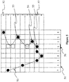
- Figure 5 diagrammatically shows the inverse projection of pixels of two projection surfaces 51 and 52 associated with two depth and texture images.
- depth value stored in pixels of images respectively associated with projection surface 51 and 52 are indicated as integers in columns and rows in front of illustrated pixels.
- a first set of 3D points generated by the inverse projection of pixels of image 51 are shown as black discs.
- a second set of 3D points generated by the inverse projection of pixels of image 52 are shown as empty squares.
- Points of the original point cloud are located along surface 50 and projected on surfaces associated with images 51 and 52. Depth and color information about points of the original point cloud is stored in pixels of image 51 and 52. Some points are projected twice, like points 53,54 and 55.
- inverse projection is evaluated as referring to a common 3D reconstructed point, for example points 53, 54 and 55. For these reconstructed points, a color has to be attributed according to values stored in pixels.
- Point 55 is generated from the inverse projection of pixels 56 and 57.
- the local curvature of the generated point cloud is evaluated for both images 51 and 52 at pixels 56 and 57.
- the depth variance for pixel 56 of image 51 is 2/9 ⁇ 0.222.
- the depth variance for pixel 57 vaults 6/9 ⁇ 0.666.
- the color attributed to the generated pixel is the color stored in the pixel for which the variance is the lowest, that is the local curvature of the surface is the flattest.
- the color of pixel 56 is attributed to point 57; color of pixel 57 is not used.
- Computing the local variance of the depth of pixels of an image has the advantage to be easy and fast to compute, for example by a GPU in a shader microprogram.
- the local variance reflects the local curvature of the surface of the reconstructed point cloud according to the projection mapping used for the considered image.
- a low variance indicates that depth values of the contiguous pixels are close to their average depth value and, so, that the 3D point cloud surface at this location is paralleled to the projection surface.
- the 3D points are assumed to be close in the 3D space. Texture of the 3d model at this location is more likely to be homogeneous and leading to low frequency of the color attributes at the corresponding location in the projection image, leading to a good of precision conservation when compressing and decompressing the texture image.
- a high variance indicates that points projected onto the n x n pixels do not belong to a plane parallel to the projection surface and two close pixels in the projection image are far from each other in the 3D space. Texture of the 3d model at this location is less likely to be, leading to a loss of precision when compressing and decompressing the texture image.
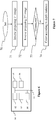
- Figure 6 represents an exemplary architecture of a device 60 which may be configured to implement a method described in relation with figure 7 .
- Device 60 comprises following elements that are linked together by a data and address bus 61:
- the battery 66 is external to the device.
- the word « register » used in the specification can correspond to area of small capacity (some bits) or to very large area (e.g. a whole program or large amount of received or decoded data).
- the ROM 63 comprises at least a program and parameters.
- the ROM 63 may store algorithms and instructions to perform techniques in accordance with present principles. When switched on, the CPU 62 uploads the program in the RAM and executes the corresponding instructions.
- RAM 64 comprises, in a register, the program executed by the CPU 62 and uploaded after switch-on of the device 60, input data in a register, intermediate data in different states of the method in a register, and other variables used for the execution of the method in a register.
- the implementations described herein may be implemented in, for example, a method or a process, an apparatus, a software program, a data stream, or a signal. Even if only discussed in the context of a single form of implementation (for example, discussed only as a method or a device), the implementation of features discussed may also be implemented in other forms (for example a program).
- An apparatus may be implemented in, for example, appropriate hardware, software, and firmware.
- the methods may be implemented in, for example, an apparatus such as, for example, a processor, which refers to processing devices in general, including, for example, a computer, a microprocessor, an integrated circuit, or a programmable logic device. Processors also include communication devices, such as, for example, computers, cell phones, portable/personal digital assistants ("PDAs”), and other devices that facilitate communication of information between end-users.
- PDAs portable/personal digital assistants
- the reconstructed point cloud is sent to a destination; specifically, the destination belongs to a set comprising:
- a bitstream encoded a first and a second image is obtained from a source.
- a bitstream is read from a local memory, e.g. a video memory 64, a RAM 64, a ROM 63, a flash memory 63 or a hard disk 63.
- the bitstream is received from a storage interface 65, e.g. an interface with a mass storage, a RAM, a ROM, a flash memory, an optical disc or a magnetic support and/or received from a communication interface 65, e.g. an interface to a point to point link, a bus, a point to multipoint link or a broadcast network.
- device 60 being configured to implement a decoding method described in relation with figure 7 , belongs to a set comprising:
- Figure 7 diagrammatically illustrates a method for encoding a three-dimensional point cloud in a stream by a device 60 of figure 6 , according to a non-restrictive embodiment of the present principles.
- a step 70 the different parameters of the device 60 are updated.
- the 3D a first image and a second image comprising depth and color attributes are obtained from a source, projection mappings are initialized and sizes and resolutions of the first and the second images are determined.
- pixels of the first image are inverse projected according to a projection mapping associated with the first image.
- the inverse projection generates 3D points of the reconstructed point cloud.
- the inverse projection of a pixel is a 3D volume determined according to the definition of the first image (i.e. the size of pixels of the first image on the corresponding 3D surface in the 3D space) and an imprecision value determined according to parameters of the compression method used for encoding the first image.
- the color stored in pixels of the first image is attributed to corresponding generated points.
- pixels of the second image are inverse projected according to a projection mapping associated with the second image.
- a test is performed to determine if the inverse projection of a second pixel of the second image refer to a point generated by the inverse projection of a first pixel of the first image, called common generated point. If the two inverse projections refer to a common generated point a step 74 is performed. Otherwise, the color of the second pixel is attributed to the generated 3D point.
- the inverse projection of the second pixel and the inverse projection of the first pixel refer to a common generated point if their associated volume overlap over a percentage threshold, for example 50% or 75%.
- the two inverse projections refer to a common generated point if the center of the volume of the inverse projection of the first pixel belongs to the volume of the inverse projection of the second pixel and reciprocally.
- Test 73 is performed while inverse projecting pixels of the second image in step 72.
- the corresponding volume is compared to points generated by the inverse projection of pixels of the first image.
- every pixel of the second is inverse projected before a test 73 is performed on generated points.
- a step 74 the local variance of the depth is evaluated for the first pixel and the second pixel.
- the color of the pixel having the lowest depth variance is attributed to the common generated point. Coordinates of the common generated point are computed to the two volumes of the two inverse projections.
- the present disclosure is not limited to the embodiments previously described.
- the present disclosure is not limited to methods and devices for decoding a stream carrying data representative of a three-dimensional point cloud (or a sequence of three-dimensional point clouds) but also extends to methods of rendering the retrieved point cloud (or sequence of point clouds) to any devices implementing these methods and notably any devices comprising at least one CPU and/or at least one GPU.
- the present disclosure also relates to a method (and a device configured) for transmitting and/or receiving the stream encoded according to the present principles.
- the implementations described herein may be implemented in, for example, a method or a process, an apparatus, a computer program product, a data stream, or a signal. Even if only discussed in the context of a single form of implementation (for example, discussed only as a method or a device), the implementation of features discussed may also be implemented in other forms (for example a program).
- An apparatus may be implemented in, for example, appropriate hardware, software, and firmware.
- the methods may be implemented in, for example, an apparatus such as, for example, a processor, which refers to processing devices in general, including, for example, a computer, a microprocessor, an integrated circuit, or a programmable logic device. Processors also include communication devices, such as, for example, Smartphones, tablets, computers, mobile phones, portable/personal digital assistants ("PDAs”), and other devices that facilitate communication of information between end-users.
- PDAs portable/personal digital assistants
- Implementations of the various processes and features described herein may be embodied in a variety of different equipment or applications, particularly, for example, equipment or applications associated with data encoding, data decoding, view generation, texture processing, and other processing of images and related texture information and/or depth information.
- equipment include an encoder, a decoder, a post-processor processing output from a decoder, a pre-processor providing input to an encoder, a video coder, a video decoder, a video codec, a web server, a set-top box, a laptop, a personal computer, a cell phone, a PDA, and other communication devices.
- the equipment may be mobile and even installed in a mobile vehicle.
- the methods may be implemented by instructions being performed by a processor, and such instructions (and/or data values produced by an implementation) may be stored on a processor-readable medium such as, for example, an integrated circuit, a software carrier or other storage device such as, for example, a hard disk, a compact diskette (“CD"), an optical disc (such as, for example, a DVD, often referred to as a digital versatile disc or a digital video disc), a random access memory (“RAM”), or a read-only memory (“ROM”).
- the instructions may form an application program tangibly embodied on a processor-readable medium. Instructions may be, for example, in hardware, firmware, software, or a combination.
- a processor may be characterized, therefore, as, for example, both a device configured to carry out a process and a device that includes a processor-readable medium (such as a storage device) having instructions for carrying out a process. Further, a processor-readable medium may store, in addition to or in lieu of instructions, data values produced by an implementation.
- implementations may produce a variety of signals formatted to carry information that may be, for example, stored or transmitted.
- the information may include, for example, instructions for performing a method, or data produced by one of the described implementations.
- a signal may be formatted to carry as data the rules for writing or reading the syntax of a described embodiment, or to carry as data the actual syntax-values written by a described embodiment.
- Such a signal may be formatted, for example, as an electromagnetic wave (for example, using a radio frequency portion of spectrum) or as a baseband signal.
- the formatting may include, for example, encoding a data stream and modulating a carrier with the encoded data stream.
- the information that the signal carries may be, for example, analog or digital information.
- the signal may be transmitted over a variety of different wired or wireless links, as is known.
- the signal may be stored on a processor-readable medium.
Landscapes
- Engineering & Computer Science (AREA)
- Physics & Mathematics (AREA)
- General Physics & Mathematics (AREA)
- Theoretical Computer Science (AREA)
- Computer Graphics (AREA)
- Geometry (AREA)
- Software Systems (AREA)
- Multimedia (AREA)
- Computer Vision & Pattern Recognition (AREA)
- Image Generation (AREA)
- Processing Or Creating Images (AREA)
- Compression Or Coding Systems Of Tv Signals (AREA)
Priority Applications (3)
| Application Number | Priority Date | Filing Date | Title |
|---|---|---|---|
| EP17306352.0A EP3467785A1 (de) | 2017-10-06 | 2017-10-06 | Verfahren und vorrichtung zur codierung einer punktwolke, die dreidimensionale objekte repräsentiert |
| EP18197880.0A EP3467786B1 (de) | 2017-10-06 | 2018-10-01 | Verfahren und vorrichtung zur codierung einer punktwolke, die dreidimensionale objekte repräsentiert |
| US16/153,719 US10964066B2 (en) | 2017-10-06 | 2018-10-06 | Method and apparatus for encoding a point cloud representing three-dimensional objects |
Applications Claiming Priority (1)
| Application Number | Priority Date | Filing Date | Title |
|---|---|---|---|
| EP17306352.0A EP3467785A1 (de) | 2017-10-06 | 2017-10-06 | Verfahren und vorrichtung zur codierung einer punktwolke, die dreidimensionale objekte repräsentiert |
Publications (1)
| Publication Number | Publication Date |
|---|---|
| EP3467785A1 true EP3467785A1 (de) | 2019-04-10 |
Family
ID=60186214
Family Applications (2)
| Application Number | Title | Priority Date | Filing Date |
|---|---|---|---|
| EP17306352.0A Withdrawn EP3467785A1 (de) | 2017-10-06 | 2017-10-06 | Verfahren und vorrichtung zur codierung einer punktwolke, die dreidimensionale objekte repräsentiert |
| EP18197880.0A Active EP3467786B1 (de) | 2017-10-06 | 2018-10-01 | Verfahren und vorrichtung zur codierung einer punktwolke, die dreidimensionale objekte repräsentiert |
Family Applications After (1)
| Application Number | Title | Priority Date | Filing Date |
|---|---|---|---|
| EP18197880.0A Active EP3467786B1 (de) | 2017-10-06 | 2018-10-01 | Verfahren und vorrichtung zur codierung einer punktwolke, die dreidimensionale objekte repräsentiert |
Country Status (2)
| Country | Link |
|---|---|
| US (1) | US10964066B2 (de) |
| EP (2) | EP3467785A1 (de) |
Cited By (3)
| Publication number | Priority date | Publication date | Assignee | Title |
|---|---|---|---|---|
| EP3742404A1 (de) * | 2019-05-22 | 2020-11-25 | Sony Interactive Entertainment Inc. | Inhaltscodierungssystem und -verfahren |
| EP3745357A1 (de) * | 2019-05-28 | 2020-12-02 | InterDigital VC Holdings, Inc. | Verfahren und vorrichtung zur decodierung dreidimensionaler szenen |
| WO2021126339A1 (en) * | 2019-12-20 | 2021-06-24 | Raytheon Company | Information weighted rendering of 3d point set |
Families Citing this family (23)
| Publication number | Priority date | Publication date | Assignee | Title |
|---|---|---|---|---|
| US10013808B2 (en) | 2015-02-03 | 2018-07-03 | Globus Medical, Inc. | Surgeon head-mounted display apparatuses |
| US20190254753A1 (en) | 2018-02-19 | 2019-08-22 | Globus Medical, Inc. | Augmented reality navigation systems for use with robotic surgical systems and methods of their use |
| WO2020230710A1 (ja) * | 2019-05-10 | 2020-11-19 | パナソニック インテレクチュアル プロパティ コーポレーション オブ アメリカ | 三次元データ符号化方法、三次元データ復号方法、三次元データ符号化装置、及び三次元データ復号装置 |
| WO2020246690A1 (ko) * | 2019-06-04 | 2020-12-10 | 엘지전자 주식회사 | 포인트 클라우드 데이터 송신 장치, 포인트 클라우드 데이터 송신 방법, 포인트 클라우드 데이터 수신 장치 및 포인트 클라우드 데이터 수신 방법 |
| CN114402624B (zh) | 2019-08-02 | 2024-07-30 | Lg电子株式会社 | 点云数据处理设备和方法 |
| US11992373B2 (en) | 2019-12-10 | 2024-05-28 | Globus Medical, Inc | Augmented reality headset with varied opacity for navigated robotic surgery |
| US12220176B2 (en) | 2019-12-10 | 2025-02-11 | Globus Medical, Inc. | Extended reality instrument interaction zone for navigated robotic |
| US12133772B2 (en) | 2019-12-10 | 2024-11-05 | Globus Medical, Inc. | Augmented reality headset for navigated robotic surgery |
| CN115023741A (zh) * | 2020-01-09 | 2022-09-06 | 松下电器(美国)知识产权公司 | 三维数据编码方法、三维数据解码方法、三维数据编码装置、以及三维数据解码装置 |
| US11464581B2 (en) | 2020-01-28 | 2022-10-11 | Globus Medical, Inc. | Pose measurement chaining for extended reality surgical navigation in visible and near infrared spectrums |
| US11382699B2 (en) | 2020-02-10 | 2022-07-12 | Globus Medical Inc. | Extended reality visualization of optical tool tracking volume for computer assisted navigation in surgery |
| US11207150B2 (en) | 2020-02-19 | 2021-12-28 | Globus Medical, Inc. | Displaying a virtual model of a planned instrument attachment to ensure correct selection of physical instrument attachment |
| US11607277B2 (en) | 2020-04-29 | 2023-03-21 | Globus Medical, Inc. | Registration of surgical tool with reference array tracked by cameras of an extended reality headset for assisted navigation during surgery |
| US11153555B1 (en) | 2020-05-08 | 2021-10-19 | Globus Medical Inc. | Extended reality headset camera system for computer assisted navigation in surgery |
| US11382700B2 (en) | 2020-05-08 | 2022-07-12 | Globus Medical Inc. | Extended reality headset tool tracking and control |
| US11510750B2 (en) | 2020-05-08 | 2022-11-29 | Globus Medical, Inc. | Leveraging two-dimensional digital imaging and communication in medicine imagery in three-dimensional extended reality applications |
| CN111707235A (zh) * | 2020-05-09 | 2020-09-25 | 广东省国土资源测绘院 | 一种基于三维激光扫描技术的地物测量方法 |
| CN111915657B (zh) * | 2020-07-08 | 2024-08-27 | 浙江大华技术股份有限公司 | 一种点云配准方法、装置、电子设备及存储介质 |
| US11737831B2 (en) | 2020-09-02 | 2023-08-29 | Globus Medical Inc. | Surgical object tracking template generation for computer assisted navigation during surgical procedure |
| CN114764825A (zh) * | 2020-12-31 | 2022-07-19 | 广东博智林机器人有限公司 | 钢筋顶点定位方法及装置 |
| CN113674369B (zh) * | 2021-07-27 | 2024-04-09 | 闽都创新实验室 | 一种深度学习采样改进g-pcc压缩的方法 |
| CN114677454B (zh) * | 2022-03-25 | 2022-10-04 | 杭州睿影科技有限公司 | 一种图像生成方法和装置 |
| CN115239784B (zh) * | 2022-07-29 | 2026-02-10 | 深圳元戎启行科技有限公司 | 点云生成方法、装置、计算机设备和存储介质 |
Family Cites Families (8)
| Publication number | Priority date | Publication date | Assignee | Title |
|---|---|---|---|---|
| US6249592B1 (en) * | 1998-05-22 | 2001-06-19 | Xerox Corporation | Multi-resolution neutral color detection |
| US7003136B1 (en) | 2002-04-26 | 2006-02-21 | Hewlett-Packard Development Company, L.P. | Plan-view projections of depth image data for object tracking |
| US9641822B2 (en) * | 2008-02-25 | 2017-05-02 | Samsung Electronics Co., Ltd. | Method and apparatus for processing three-dimensional (3D) images |
| US9336625B2 (en) * | 2011-10-25 | 2016-05-10 | Microsoft Technology Licensing, Llc | Object refinement using many data sets |
| US8854433B1 (en) | 2012-02-03 | 2014-10-07 | Aquifi, Inc. | Method and system enabling natural user interface gestures with an electronic system |
| US8836768B1 (en) | 2012-09-04 | 2014-09-16 | Aquifi, Inc. | Method and system enabling natural user interface gestures with user wearable glasses |
| US9772405B2 (en) | 2014-10-06 | 2017-09-26 | The Boeing Company | Backfilling clouds of 3D coordinates |
| US10373366B2 (en) * | 2015-05-14 | 2019-08-06 | Qualcomm Incorporated | Three-dimensional model generation |
-
2017
- 2017-10-06 EP EP17306352.0A patent/EP3467785A1/de not_active Withdrawn
-
2018
- 2018-10-01 EP EP18197880.0A patent/EP3467786B1/de active Active
- 2018-10-06 US US16/153,719 patent/US10964066B2/en active Active
Non-Patent Citations (5)
| Title |
|---|
| CHOI CHANGHYUN ET AL: "RGB-D edge detection and edge-based registration", 2013 IEEE/RSJ INTERNATIONAL CONFERENCE ON INTELLIGENT ROBOTS AND SYSTEMS, IEEE, 3 November 2013 (2013-11-03), pages 1568 - 1575, XP032537516, ISSN: 2153-0858, [retrieved on 20131226], DOI: 10.1109/IROS.2013.6696558 * |
| IRENE REISNER-KOLLMANN ET AL: "Consolidation of multiple depth maps", COMPUTER VISION WORKSHOPS (ICCV WORKSHOPS), 2011 IEEE INTERNATIONAL CONFERENCE ON, IEEE, 6 November 2011 (2011-11-06), pages 1120 - 1126, XP032095372, ISBN: 978-1-4673-0062-9, DOI: 10.1109/ICCVW.2011.6130375 * |
| LEMBIT VALGMA: "3D reconstruction using Kinect v2 cameraBachelors thesis (12 ECTP)", 20 May 2016 (2016-05-20), pages 1 - 42, XP002778994, Retrieved from the Internet <URL:https://www.tuit.ut.ee/sites/default/files/tuit/atprog-courses-bakalaureuset55-loti.05.029-lembit-valgma-text-20160520.pdf> [retrieved on 20180312] * |
| PETER SCHEKKENS: "JPEG PLENO - Scope, use cases and requirements Ver.1.3", 71. JPEG MEETING;22-2-2016 - 26-2-2016; LA JOTTA; (JOINT PICTURE EXPERT GROUP OR ISO/IEC JTC1/SC29/WG1), no. wg1m71003, 14 December 2016 (2016-12-14), pages 18PP, XP030190032 * |
| TILO OCHOTTA ET AL: "Compression of Point-Based 3D Models by Shape-Adaptive Wavelet Coding of Multi-Height Fields", EUROGRAPHICS SYMPOSIUM ON POINT-BASED GRAPHICS, 1 January 2004 (2004-01-01), XP055397079, Retrieved from the Internet <URL:https://www.uni-konstanz.de/mmsp/pubsys/publishedFiles/OcSa04.pdf> [retrieved on 20180312], DOI: 10.2312/SPBG/SPBG04/103-112 * |
Cited By (8)
| Publication number | Priority date | Publication date | Assignee | Title |
|---|---|---|---|---|
| EP3742404A1 (de) * | 2019-05-22 | 2020-11-25 | Sony Interactive Entertainment Inc. | Inhaltscodierungssystem und -verfahren |
| EP3745357A1 (de) * | 2019-05-28 | 2020-12-02 | InterDigital VC Holdings, Inc. | Verfahren und vorrichtung zur decodierung dreidimensionaler szenen |
| WO2020243089A1 (en) * | 2019-05-28 | 2020-12-03 | Interdigital Vc Holdings, Inc. | A method and apparatus for decoding three-dimensional scenes |
| CN114051734A (zh) * | 2019-05-28 | 2022-02-15 | 交互数字Vc控股公司 | 一种解码三维场景的方法和装置 |
| US11721044B2 (en) | 2019-05-28 | 2023-08-08 | Interdigital Vc Holdings, Inc. | Method and apparatus for decoding three-dimensional scenes |
| CN114051734B (zh) * | 2019-05-28 | 2026-02-13 | 交互数字Vc控股公司 | 一种解码三维场景的方法和装置 |
| WO2021126339A1 (en) * | 2019-12-20 | 2021-06-24 | Raytheon Company | Information weighted rendering of 3d point set |
| US11682142B2 (en) | 2019-12-20 | 2023-06-20 | Raytheon Company | Information weighted rendering of 3D point set |
Also Published As
| Publication number | Publication date |
|---|---|
| EP3467786A1 (de) | 2019-04-10 |
| EP3467786B1 (de) | 2022-02-16 |
| US10964066B2 (en) | 2021-03-30 |
| US20190108654A1 (en) | 2019-04-11 |
Similar Documents
| Publication | Publication Date | Title |
|---|---|---|
| EP3467786B1 (de) | Verfahren und vorrichtung zur codierung einer punktwolke, die dreidimensionale objekte repräsentiert | |
| US12249107B2 (en) | Method and apparatus for encoding and decoding three-dimensional scenes in and from a data stream | |
| US11721044B2 (en) | Method and apparatus for decoding three-dimensional scenes | |
| EP3468182A1 (de) | Verfahren und vorrichtung zur codierung einer punktwolke, die dreidimensionale objekte repräsentiert | |
| US10055893B2 (en) | Method and device for rendering an image of a scene comprising a real object and a virtual replica of the real object | |
| US11375235B2 (en) | Method and apparatus for encoding and decoding three-dimensional scenes in and from a data stream | |
| EP3562159A1 (de) | Verfahren, vorrichtung und stream für volumenvideoformat | |
| US12579729B2 (en) | Volumetric video supporting light effects | |
| US11798195B2 (en) | Method and apparatus for encoding and decoding three-dimensional scenes in and from a data stream | |
| US12212784B2 (en) | Different atlas packings for volumetric video | |
| JP2023506832A (ja) | 補助パッチを有する容積ビデオ | |
| US12167034B2 (en) | Method and apparatus for encoding and decoding volumetric video | |
| WO2020190898A1 (en) | A method and apparatus for depth encoding and decoding | |
| US12368831B2 (en) | Method and apparatus for encoding and decoding volumetric content in and from a data stream | |
| EP3467781A1 (de) | Verfahren und anordnung zum upsampling eines satzes von punkten, die eine 3d szene darstellen |
Legal Events
| Date | Code | Title | Description |
|---|---|---|---|
| PUAI | Public reference made under article 153(3) epc to a published international application that has entered the european phase |
Free format text: ORIGINAL CODE: 0009012 |
|
| AK | Designated contracting states |
Kind code of ref document: A1 Designated state(s): AL AT BE BG CH CY CZ DE DK EE ES FI FR GB GR HR HU IE IS IT LI LT LU LV MC MK MT NL NO PL PT RO RS SE SI SK SM TR |
|
| AX | Request for extension of the european patent |
Extension state: BA ME |
|
| STAA | Information on the status of an ep patent application or granted ep patent |
Free format text: STATUS: THE APPLICATION IS DEEMED TO BE WITHDRAWN |
|
| 18D | Application deemed to be withdrawn |
Effective date: 20191011 |