EP3467818B1 - Dispositif de création de champ acoustique atténué localement, procédé et programme d'ordinateur correspondants - Google Patents
Dispositif de création de champ acoustique atténué localement, procédé et programme d'ordinateur correspondants Download PDFInfo
- Publication number
- EP3467818B1 EP3467818B1 EP17806380.6A EP17806380A EP3467818B1 EP 3467818 B1 EP3467818 B1 EP 3467818B1 EP 17806380 A EP17806380 A EP 17806380A EP 3467818 B1 EP3467818 B1 EP 3467818B1
- Authority
- EP
- European Patent Office
- Prior art keywords
- speaker
- drive signal
- silenced
- sound field
- speaker array
- Prior art date
- Legal status (The legal status is an assumption and is not a legal conclusion. Google has not performed a legal analysis and makes no representation as to the accuracy of the status listed.)
- Active
Links
Images





Classifications
-
- H—ELECTRICITY
- H04—ELECTRIC COMMUNICATION TECHNIQUE
- H04R—LOUDSPEAKERS, MICROPHONES, GRAMOPHONE PICK-UPS OR LIKE ACOUSTIC ELECTROMECHANICAL TRANSDUCERS; ELECTRIC HEARING AIDS; PUBLIC ADDRESS SYSTEMS
- H04R1/00—Details of transducers, loudspeakers or microphones
- H04R1/20—Arrangements for obtaining desired frequency or directional characteristics
- H04R1/32—Arrangements for obtaining desired frequency or directional characteristics for obtaining desired directional characteristic only
- H04R1/40—Arrangements for obtaining desired frequency or directional characteristics for obtaining desired directional characteristic only by combining a number of identical transducers
- H04R1/403—Arrangements for obtaining desired frequency or directional characteristics for obtaining desired directional characteristic only by combining a number of identical transducers loud-speakers
-
- G—PHYSICS
- G10—MUSICAL INSTRUMENTS; ACOUSTICS
- G10K—SOUND-PRODUCING DEVICES; METHODS OR DEVICES FOR PROTECTING AGAINST, OR FOR DAMPING, NOISE OR OTHER ACOUSTIC WAVES IN GENERAL; ACOUSTICS NOT OTHERWISE PROVIDED FOR
- G10K11/00—Methods or devices for transmitting, conducting or directing sound in general; Methods or devices for protecting against, or for damping, noise or other acoustic waves in general
- G10K11/16—Methods or devices for protecting against, or for damping, noise or other acoustic waves in general
- G10K11/175—Methods or devices for protecting against, or for damping, noise or other acoustic waves in general using interference effects; Masking sound
- G10K11/178—Methods or devices for protecting against, or for damping, noise or other acoustic waves in general using interference effects; Masking sound by electro-acoustically regenerating the original acoustic waves in anti-phase
-
- G—PHYSICS
- G10—MUSICAL INSTRUMENTS; ACOUSTICS
- G10K—SOUND-PRODUCING DEVICES; METHODS OR DEVICES FOR PROTECTING AGAINST, OR FOR DAMPING, NOISE OR OTHER ACOUSTIC WAVES IN GENERAL; ACOUSTICS NOT OTHERWISE PROVIDED FOR
- G10K11/00—Methods or devices for transmitting, conducting or directing sound in general; Methods or devices for protecting against, or for damping, noise or other acoustic waves in general
- G10K11/18—Methods or devices for transmitting, conducting or directing sound
- G10K11/26—Sound-focusing or directing, e.g. scanning
- G10K11/34—Sound-focusing or directing, e.g. scanning using electrical steering of transducer arrays, e.g. beam steering
-
- H—ELECTRICITY
- H04—ELECTRIC COMMUNICATION TECHNIQUE
- H04R—LOUDSPEAKERS, MICROPHONES, GRAMOPHONE PICK-UPS OR LIKE ACOUSTIC ELECTROMECHANICAL TRANSDUCERS; ELECTRIC HEARING AIDS; PUBLIC ADDRESS SYSTEMS
- H04R1/00—Details of transducers, loudspeakers or microphones
- H04R1/20—Arrangements for obtaining desired frequency or directional characteristics
- H04R1/32—Arrangements for obtaining desired frequency or directional characteristics for obtaining desired directional characteristic only
- H04R1/40—Arrangements for obtaining desired frequency or directional characteristics for obtaining desired directional characteristic only by combining a number of identical transducers
-
- H—ELECTRICITY
- H04—ELECTRIC COMMUNICATION TECHNIQUE
- H04R—LOUDSPEAKERS, MICROPHONES, GRAMOPHONE PICK-UPS OR LIKE ACOUSTIC ELECTROMECHANICAL TRANSDUCERS; ELECTRIC HEARING AIDS; PUBLIC ADDRESS SYSTEMS
- H04R3/00—Circuits for transducers
Definitions
- the present technology relates to a locally silenced sound field forming apparatus and method, and a program, and more particularly relates to a locally silenced sound field forming apparatus and method, and a program capable of controlling a silenced area in a depth direction.
- Conventional methods for suppressing a sound in a specific area in formation of a sound field include a method of performing directivity control using a parametric speaker or a linear speaker array.
- Non-Patent Document 1 there is a proposed method of local silencing by super-directivity control using a parametric speaker (refer to Non-Patent Document 1, for example). This method arranges units of the parametric speaker in the horizontal direction or physically moving or rotating the unit to enable moving an area to be silenced in the left and right directions as viewed from the speaker.
- Non-Patent Document 1 Kamakura et al., "Practical development of a parametric loudspeaker,” Journal of Acoustical Society of Japan, vol. 62, p. 791-797, 2006 .
- the above-described technique has difficulty in controlling the area to be silenced in the depth direction as viewed from the speaker.
- it is difficult to provide the silenced area at a desired position in the depth direction.
- the present technology has been made in view of such a situation, and aims to achieve control of silenced area in the depth direction.
- a locally silenced sound field forming apparatus includes: a first speaker array that outputs a sound on the basis of a first speaker drive signal to form a predetermined sound field; and a second speaker array arranged at a position different from the position of the first speaker array and that outputs a sound on the basis of a second speaker drive signal to form a sound field that cancels the predetermined sound field.
- the locally silenced sound field forming apparatus can further include: an acquisition unit that obtains information regarding a silenced area that cancels the predetermined sound field; and a drive signal generation unit that generates the first speaker drive signal and the second speaker drive signal on the basis of the information regarding the silenced area.
- the acquisition unit can be configured to obtain, as the information regarding the silenced area, a first distance from the first speaker array to the silenced area and a second distance from the second speaker array to the silenced area.
- the drive signal generation unit can be configured to generate the second speaker drive signal that forms a sound field having an inverted phase of that in the predetermined sound field in the silenced area.
- a locally silenced sound field forming apparatus includes: a first speaker array that outputs a sound on the basis of a first speaker drive signal to form a predetermined sound field; and a second speaker array arranged at a position different from the position of the first speaker array and that outputs a sound on the basis of a second speaker drive signal to form a sound field that cancels the predetermined sound field in a silenced area.
- the locally silenced sound field forming apparatus further includes: an acquisition unit that obtains information regarding the silenced area where the sound output by the second speaker array cancels the predetermined sound field; and a drive signal generation unit that generates the first speaker drive signal and the second speaker drive signal on the basis of the information regarding the silenced area.
- the acquisition unit is configured to obtain, as the information regarding the silenced area, a first distance from the first speaker array to the silenced area and a second distance from the second speaker array to the silenced area.
- the drive signal generation unit can be configured to generate the second speaker drive signal that forms a sound field having an inverted phase of that in the predetermined sound field in the silenced area.
- the drive signal generation unit is configured to generate a first spatial frequency spectrum of the first speaker drive signal on the basis of the first distance and generate a second spatial frequency spectrum of the second speaker drive signal on the basis of the second distance, and it is further provided a spatial frequency combining unit that performs spatial frequency combining on each of the first spatial frequency spectrum and the second spatial frequency spectrum to generate a first temporal frequency spectrum and a second temporal frequency spectrum, respectively; and a temporal frequency combining unit that performs temporal frequency combining on each of the first temporal frequency spectrum and the second temporal frequency spectrum to generate the first speaker drive signal and the second speaker drive signal, respectively.
- the drive signal generation unit can be configured to convolute a filter coefficient corresponding to the first distance, and a sound source signal, to generate the first speaker drive signal, and convolute a filter coefficient corresponding to the second distance, and the sound source signal, to generate the second speaker drive signal.
- the locally silenced sound field forming apparatus can include a plurality of the second speaker arrays.
- Distances between the first speaker array and each of the plurality of second speaker arrays can be different from each other.
- the first speaker array and the second speaker array can be each provided as a linear speaker array or an annular speaker array.
- a locally silenced sound field forming method or program according to claims 7 and 8 and to an aspect of the present technology is a locally silenced sound field forming method or program for a locally silenced sound field forming apparatus including a first speaker array and a second speaker array arranged at a different position from the first speaker array, the method or program including: outputting a sound by the first speaker array on the basis of a first speaker drive signal to form a predetermined sound field; and outputting a sound by the second speaker array on the basis of a second speaker drive signal to form a sound field that cancels the predetermined sound field.
- a sound is output by the first speaker array on the basis of a first speaker drive signal to form a predetermined sound field
- a sound is output by the second speaker array on the basis of a second speaker drive signal to form a sound field that cancels the predetermined sound field.
- effects described herein are non-restricting.
- the effects may be any effects described in the present disclosure.
- the present technology uses two speaker arrays having different arrangement positions so as to enable providing a silenced area on a desired control point in the depth direction as viewed from the speaker.
- the present technology uses two speaker arrays to form a sound field simultaneously including: a region in which the sound locally decreases only at a point a specific distance away from the speaker array (hereinafter referred to as a silenced area); and a region in which sounds can be heard and located in front and rear of the silenced area (hereinafter referred to as a "reproduction area”), in a depth direction as viewed from the speaker arrays.
- a silenced area a region in which the sound locally decreases only at a point a specific distance away from the speaker array
- a region in which sounds can be heard and located in front and rear of the silenced area hereinafter referred to as a "reproduction area”
- the present technology uses two speaker arrays, namely, a speaker array SPA 11-1 and a speaker array SPA 11-2, to form a silenced area RM 11, and reproduction areas RP 11-1 and RP 11-2 respectively positioned in front and rear of the silenced area RM 11, as illustrated in Fig. 1 .
- the shading in Fig. 1 indicates sound pressure at each of positions of the sound fields formed.
- the two speaker arrays namely, the speaker array SPA 11-1 and the speaker array SPA 11-2, each of which being formed with a plurality of speakers arranged in the horizontal direction (hereinafter referred to as an x-direction) in the figure, are arranged in the vertical direction (hereinafter referred to as a "y-direction") with a predetermined distance between each other in the figure.
- one of the two speaker arrays namely, the speaker array SPA 11-1 and the speaker array SPA 11-2, is a speaker array for forming a desired sound field, while the other is a speaker array for forming a sound field that cancels the desired sound field on a predetermined control point.
- the speaker array SPA 11-1 and the speaker array SPA 11-2 will also be simply referred to as the speaker array SPA 11 unless there is no particular need to make a distinction.
- speaker array SPA 11 is illustrated as a linear speaker array in this example, it is not limited to this, and a planar speaker array obtained by arranging speakers on a flat surface, an annular speaker array obtained by arranging speakers in an annular (circular) shape, or the like may be used as the speaker array SPA 11.
- several speakers may be selected to be used as an annular speaker array from among the speakers constituting the spherical speaker array, or several speakers may be selected to be used as a linear speaker array from among the speakers constituting the planar speaker array.
- the example illustrated in Fig. 1 is a sound field formation using the two speaker arrays SPA 11, in which the reproduction area RP 11-1, the silenced area RM 11, and the reproduction area RP 11-2 are formed to be arranged in the y-direction that is the direction perpendicular to the direction in which the speakers constituting the speaker array SPA 11 are arranged. That is, the silenced area RM 11 being a locally silenced region is formed at a desired position in the depth direction as viewed from the speaker array SPA 11.
- the control point of the speaker array SPA 11 is a position where the distance in a direction that is perpendicular to the direction in which the speakers constituting the speaker array SPA 11 are arranged, that is, in the y-direction in Fig. 1 is a predetermined distance as viewed from the speaker array SPA 11. Accordingly, the control point is on a straight line parallel to the speaker array SPA 11, that is, a straight line parallel to the x-direction.
- the sound pressure and the phase can be set to be agreement with an ideal desired sound field on the control point, while an error occurs in the sound pressure in the other areas.
- the present technology utilizes this error to form the silenced area RM 11 by means of the two speaker arrays SPA 11.
- the center position of the speaker array SPA 21 being a linear speaker array is set as an origin O of a three-dimensional orthogonal coordinate system.
- the speaker array SPA 21 corresponds to the speaker array SPA 11 illustrated in Fig. 1 and a speaker array of a locally silenced sound field forming apparatus to be described later.
- the speaker array SPA 21 includes a plurality of speakers arranged linearly in the horizontal direction in the figure.
- three axes of the three-dimensional orthogonal coordinate system are defined as an x-axis, a y-axis, and a z-axis passing through the origin O and orthogonal to each other.
- the direction of the x-axis that is, the x-direction is defined as a direction in which the speakers constituting the speaker array SPA 21 are arranged.
- the direction of the y-axis that is, the y-direction is defined as a direction parallel to the direction in which a sound wave is output from the speaker array SPA 21, while a direction perpendicular to the x-direction and the y-direction is defined as the z-axis direction, that is, the z-direction.
- the direction in which the sound wave is output from the speaker array SPA 21 is defined as a positive direction in the y-direction.
- a spatial position that is, a vector indicating a spatial position will also be represented as (x, y, z) using the x-coordinate, the y-coordinate, and the z-coordinate.
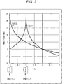
- Fig. 3 corresponding to those in Fig. 1 are denoted by the same reference numerals, and description thereof is omitted. Furthermore, in Fig. 3 , the horizontal axis indicates the position in the y-direction and the vertical axis indicates the sound pressure.
- a curve LA 11 illustrates a sound pressure at each of positions of the sound reproduced by the speaker array SPA 11-2
- a curve LA 12 illustrates a sound pressure at each of positions of the sound reproduced by the speaker array SPA 11-1.
- a reproduction area as an audible area is produced in the regions in front and rear of the silenced area in the y-direction, due to the difference in the sound reproduced by each of the two speaker arrays SPA 11, that is, the difference in the sound pressures of individual sound fields.
- this mechanism it is possible to form the reproduction area RP 11-1, the silenced area RM 11, and the reproduction area RP 11-2, as illustrated in Fig. 1 , for example.
- the silenced area can be moved in the y-direction with a certain degree of freedom.
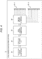
- Fig. 4 is a diagram illustrating a configuration example of an embodiment of a locally silenced sound field forming apparatus according to the present technology
- the locally silenced sound field forming apparatus 11 illustrated in Fig. 4 includes a silenced area position acquisition unit 21, a drive signal generation unit 22, a spatial frequency combining unit 23, a temporal frequency combining unit 24, a speaker array 25-1, and a speaker array 25-2.
- the speaker array 25-1 and the speaker array 25-2 will also be referred to simply as the speaker array 25 unless there is no particular need to make a distinction.
- the locally silenced sound field forming apparatus 11 is effective in a case where the positions of the speaker array 25-1 and the speaker array 25-2 and the position of the silenced area are substantially fixed and are not frequently changed, for example.
- the locally silenced sound field forming apparatus 11 there is no need to perform filter coefficient convolution processing on sound source signals required in a second embodiment.
- the silenced area position acquisition unit 21 obtains a distance y ref1 in the y-direction from the speaker array 25-1 to the position to be the silenced area and a distance y ref2 in the y-direction from the speaker array 25-2 to the position to be the silenced area, as information regarding the silenced area, and supplies the obtained information to the drive signal generation unit 22.
- the drive signal generation unit 22 On the basis of the distance y ref1 and the distance y ref2 supplied from the silenced area position acquisition unit 21, the drive signal generation unit 22 generates, for each of the speaker arrays 25, a spatial frequency spectrum of a speaker drive signal for allowing the speaker array 25 to reproduce the sound and supplies the generated spectrum to the spatial frequency combining unit 23.
- the spatial frequency combining unit 23 performs spatial frequency combining on the spatial frequency spectrum of the speaker drive signal supplied from the drive signal generation unit 22 for each of the speaker arrays 25 and supplies a temporal frequency spectrum thus obtained to the temporal frequency combining unit 24.
- the temporal frequency combining unit 24 For each of the speaker arrays 25, the temporal frequency combining unit 24 performs temporal frequency combining on the temporal frequency spectrum supplied from the spatial frequency combining unit 23 so as to obtain a speaker drive signal of the speaker array 25 which is a temporal signal. The temporal frequency combining unit 24 supplies the obtained speaker drive signal to the speaker array 25 to reproduce the sound.
- the speaker array 25-1 and the speaker array 25-2 include a linear speaker array, a planar speaker array, and the like, for example, and reproduce sounds on the basis of the speaker drive signal supplied from the temporal frequency combining unit 24.
- the speaker array 25-1 outputs a sound on the basis of the speaker drive signal to form a predetermined sound field
- the speaker array 25-2 outputs a sound on the basis of the speaker drive signal to form a sound field that cancels the sound field formed by the speaker array 25-1.
- a reproduction area and a silenced area are formed, achieving formation of the locally silenced sound field in which the sound field is locally silenced.
- the speaker array 25-1 and the speaker array 25-2 respectively correspond to the speaker array SPA 11-1 and the speaker array SPA 11-2 illustrated in Fig. 1 , and are arranged at different positions from each other. Specifically, the two speaker arrays 25 are arranged at mutually different positions in the y-direction.
- the positions of the two speaker arrays 25 in the x-direction and the positions in the z-direction may be configured to be different from each other, and it would be possible to realize the formation of the locally silenced sound field particularly even in a case where the position in the z-direction alone is different. Still, the following description will be given on the assumption that the positions of the speaker arrays 25 are different only in the y-direction.
- the silenced area position acquisition unit 21 obtains the distance y ref1 and the distance y ref2 to the silenced area.
- the silenced area position acquisition unit 21 may be configured to obtain the distance y ref1 and the distance y ref2 that are supplied from an external device or input by a user or the like.
- the silenced area position acquisition unit 21 detects the position to be the silenced area to calculate the distance y ref1 and the distance y ref2 so as to obtain the distance y ref1 and the distance y ref2 .
- the silenced area position acquisition unit 21 includes a camera, a sensor, or the like, in a case where the silenced area position acquisition unit 21 detects the position to be the silenced area.
- the silenced area position acquisition unit 21 recognizes an object such as a listener using the camera or the sensor, and detects the position of the silenced area on the basis of a recognition result.
- the silenced area position acquisition unit 21 detects a user from an image photographed by the camera, determines the position to be the silenced area from the detection result, as well as calculating the spatial distance from the speaker array 25 to the position to be the silenced area in the y-direction as the distance y ref1 and the distance y ref2 .
- the position of the user to whom the sound is to be suppressed among the detected users is set as the position of the silenced area.
- the drive signal generation unit 22 calculates the spatial frequency spectrum of the speaker drive signal of each of the speaker arrays 25 on the basis of the distance y ref1 and the distance y ref2 obtained as silenced area position information.
- a sound field P(v, n tf ) in three-dimensional free space is expressed as illustrated in the following Formula (1).
- P v n tf ⁇ ⁇ ⁇ ⁇ D v 0 n tf G v v 0 n tf dx 0
- n tf indicates a temporal frequency index
- v is a vector indicating a spatial position
- v (x, y, z).
- D(v 0 , n tf ) represents a drive signal of a secondary sound source
- G(v, v 0 , n tf ) is a transfer function between the position v and the position v 0
- the drive signal D(v 0 , n tf ) of the secondary sound source corresponds to the speaker drive signal of the speaker constituting the speaker array 25.
- the calculation of Formula (1) takes a form of convolution of the drive signal D(v 0 , n tf ) and the transfer function G(v, v 0 , n tf ) in the spatial domain, and the sound field P(v, n tf ) illustrated in Formula (1) can be spatially Fourier transformed in the x-axis direction, into the following Formula (2).
- P F n sf y z n tf D F n sf n tf G F n sf y z n tf
- n sf represents the spatial frequency index
- the sound field P F (n sf , y, z, n tf ) in the spatial frequency domain is expressed by the product of the drive signal D F (n sf , n tf ) and the transfer function G F (n sf , y, z, n tf ), as indicated by Formula (2) .
- the spatial frequency representation of the drive signal of the secondary sound source is as illustrated in the following Formula (3).
- D F n sf n tf P F n sf y z n tf G F n sf y z n tf
- Formula (3) can be expressed by the following Formula (4).
- D F n sf n tf P F n sf , y ref ,0 , n tf G F n sf , y ref ,0 , n tf
- S(n tf ) indicates a sound source signal of a sound to be reproduced
- j indicates an imaginary unit
- k x indicates a wave number in the x-axis direction.
- x ps and y ps indicate x and y-coordinates indicating the position of the point sound source respectively
- ⁇ indicates an angular frequency
- c indicates sound velocity.
- H 0 (2) indicates the second-type Hankel function
- K 0 indicates the Bessel function.
- G F (n sf , y ref , 0, n tf ) can be expressed by the following Formula (6) .
- G F n sf , y ref ,0 , n tf ⁇ ⁇ j 4 H 0 2 ⁇ c 2 + k x 2 y ref , k x ⁇ ⁇ c 1 2 ⁇ ⁇ K 0 k x 2 ⁇ ⁇ c 2 y ref , ⁇ c ⁇ k x
- the drive signal generation unit 22 obtains a spatial frequency spectrum D F1 (n sf , n tf ) of the speaker drive signal of the speaker array 25-1 and a spatial frequency spectrum D F2 (n sf , n tf ) of the speaker drive signal of the speaker array 25-2.
- the sound field P F (n sf , y ref , 0, n tf ) of the one speaker array 25 is to be set to -P F (n sf , y ref , 0, n tf ).
- the drive signal generation unit 22 After acquisition of the spatial frequency spectrum D F1 (n sf , n tf ) and the spatial frequency spectrum D F2 (n sf , n tf ) for the two speaker arrays 25 as described above, the drive signal generation unit 22 supplies those spatial frequency spectra to the spatial frequency combining unit 23. Note that hereinafter, the spatial frequency spectrum D F1 (n sf , n tf ) and the spatial frequency spectrum D F2 (n sf , n tf ) will also be simply referred to as the spatial frequency spectrum D F (n sf , n tf ) unless there is no particular need to make a distinction.
- the spatial frequency combining unit 23 uses discrete Fourier transform (DFT) to apply spatial frequency combining on the speaker drive signal supplied from the drive signal generation unit 22, that is, on the spatial frequency spectrum D F (n sf , n tf ), so as to obtain a temporal frequency spectrum D(l, n tf ).
- DFT discrete Fourier transform
- the spatial frequency combining unit 23 uses the following Formula (7) to calculate the temporal frequency spectrum D(l, n tf ).
- DFT discrete Fourier transform
- 1 denotes the speaker index for identifying the speaker constituting the speaker array 25, while M ds denotes the number of samples of the DFT.
- the spatial frequency combining unit 23 calculates the temporal frequency spectrum D(l, n tf ) for each of the speaker arrays 25, and supplies the temporal frequency spectrum D(l, n tf ) thus obtained to the temporal frequency combining unit 24.
- the calculation of Formula (7) is performed for each of the spatial frequency spectrum D F1 (n sf , n tf ) and the spatial frequency spectrum D F2 (n sf , n tf ) so as to obtain the temporal frequency spectrum D(l, n tf ).
- the temporal frequency combining unit 24 uses inverse discrete Fourier transform (IDFT) to apply temporal frequency combining on the temporal frequency spectrum D(l, n tf ) supplied from the spatial frequency combining unit 23 so as to obtain a speaker drive signal d(l, n d ) of each of the speakers of the speaker array 25, as a temporal signal. Specifically, the temporal frequency combining unit 24 performs calculation of the following Formula (8) to calculate the speaker drive signal d(l, n d ).
- IDFT inverse discrete Fourier transform
- n d indicates a time index
- M dt indicates the number of samples of the IDFT.
- the temporal frequency combining unit 24 calculates Formula (8) for each of the temporal frequency spectrum D(l, n tf ) of the speaker array 25-1 and the temporal frequency spectrum D(l, n tf ) of the speaker array 25-2 so as to obtain the speaker drive signal d(l, n d ) of each of the speaker arrays 25, and supplies the obtained signal to the speaker array 25.
- step S11 the silenced area position acquisition unit 21 obtains a distance from the speaker array 25 to the position to be the silenced area for each of the two speaker arrays 25, and supplies the obtained distance to the drive signal generation unit 22.
- step S11 is used to obtain the distance y ref1 and the distance y ref2 from the user's position detected by a sensor as the silenced area position acquisition unit 21 and from the positions of the speaker array 25-1 and the speaker array 25-2.
- the silenced area position acquisition unit 21 it is also allowable to first detect a user by face recognition or object recognition from an image obtained by a camera as the silenced area position acquisition unit 21 and then detect the user's position on the space on the basis of the detection result.
- a distance to the position to be the silenced area can be obtained from the user's position obtained and the position of the speaker array 25.
- step S12 the drive signal generation unit 22 uses the above-described Formulas (4) to (6) to calculate the spatial frequency spectrum D F1 (n sf , n tf ) and the spatial frequency spectrum D F2 (n sf , n tf ) of the speaker drive signal of each of the speaker arrays 25 on the basis of the distance y ref1 and the distance y ref2 supplied from the silenced area position acquisition unit 21. Then, the drive signal generation unit 22 supplies the obtained spatial frequency spectrum to the spatial frequency combining unit 23.
- the drive signal generation unit 22 generates the two spatial frequency spectra D F (n sf , n tf ) so as to form a desired sound field on the control point, that is, in a region to be a silenced area by one spatial frequency spectrum D F (n sf , n tf ), and so as to form a sound field having an inverted phase of that of the desired sound field on the control point by the other spatial frequency spectrum D F (n sf , n tf ) .
- the spatial frequency combining unit 23 calculates Formula (7) to perform spatial frequency combining on the spatial frequency spectrum D F (n sf , n tf ) supplied from the drive signal generation unit 22, and supplies the resultant temporal frequency spectrum D(l, n tf ) to the temporal frequency combining unit 24. Note that spatial frequency combining is performed for each of spatial frequency spectra D F (n sf , n tf ) of the speaker array 25.
- step S14 the temporal frequency combining unit 24 calculates Formula (8) to perform temporal frequency combining on the temporal frequency spectrum D(l, n tf ) supplied from the spatial frequency combining unit 23 so as to obtain the speaker drive signal d(l, n d ).
- the speaker drive signal d(l, n d ) is obtained for each of the speakers of the speaker array 25.
- the temporal frequency combining unit 24 supplies each of the speaker drive signals obtained for each of the speaker arrays 25 to each of the speaker array 25-1 and the speaker array 25-2 so as to reproduce the sound.
- step S15 the speaker array 25 reproduces the sound on the basis of the speaker drive signal supplied from the temporal frequency combining unit 24, so as to complete the locally silenced sound field forming processing.
- Reproduction of the sound by the speaker array 25-1 and the speaker array 25-2 forms a sound field in which a silenced area is formed in a part of the reproduction space, that is, forms a locally silenced sound field.
- the locally silenced sound field forming apparatus 11 obtains the distance to the silenced area, generates the speaker drive signal on the basis of the obtained distance, and forms a sound field by using the two speaker arrays 25 on the basis of the speaker drive signal.
- a locally silencing filter for forming a sound field with a locally silenced area provided for each of distances from the speaker array 25 to the position to be a silenced area so as to generate a speaker drive signal by using the locally silencing filter.
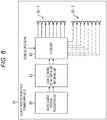
- the locally silenced sound field forming apparatus is configured as illustrated in Fig. 6 , for example. Note that portions in Fig. 6 corresponding to those in Fig. 4 are denoted by the same reference numerals, and description thereof is appropriately omitted.
- a locally silenced sound field forming apparatus 51 illustrated in Fig. 6 includes the silenced area position acquisition unit 21, a locally silencing filter coefficient recording unit 61, a filter unit 62, the speaker array 25-1, and the speaker array 25-2.
- the locally silencing filter coefficient recording unit 61 records a coefficient of a locally silencing filter being an audio filter for forming a sound field including a locally silenced area, for example, for each of distances from the speaker array 25 to the position to be a silenced area, that is, for each of the distance y ref1 and the distance y ref2 .
- the locally silencing filter coefficient recording unit 61 selects one locally silencing filter coefficient for each of the speaker arrays 25 and supplies the selected coefficient to the filter unit 62.
- the filter unit 62 convolutes the sound source signal supplied from the outside and the filter coefficients of the locally silencing filter supplied from the locally silencing filter coefficient recording unit 61 for each of the speaker arrays 25 so as to obtain a speaker drive signal, and supplies the obtained signal to the speaker array 25.
- such a filter unit 62 functions as a drive signal generation unit that generates a speaker drive signal by convoluting the locally silencing filter coefficient corresponding to the distance from the speaker array 25 to the silenced area as information regarding the silenced area together with the sound source signal.
- the positions of the speaker array 25 and the silenced area are variable, making it particularly effective in a case where the position of the silenced area is frequently updated following a person, for example.
- the locally silencing filter coefficient recording unit 61 records coefficients of the locally silencing filter for each of distances from the speaker array 25 to the position of the silenced area, such as the distance y ref1 and the distance y ref2 .
- this locally silencing filter is a filter having a filter coefficient h(l, n) for each of the speaker index 1 and the time index n.
- the locally silencing filter having such a filter coefficient h(l, n) may be configured to be achieved in a similar manner as the method of calculating the speaker drive signal described in the above first embodiment, for example.
- the sound source signal S(n tf ) 1 in acquisition of the filter coefficient h(l, n) is set because the locally silencing filter does not depend on a sound source, that is, a sound source signal.
- the locally silencing filter coefficient recording unit 61 preliminarily records filter coefficients of the locally silencing filters obtained for individual distances y ref .
- the locally silencing filter coefficient recording unit 61 records the locally silencing filter coefficients obtained for the individual distances y ref for each of the speaker arrays 25.
- the locally silencing filter of the speaker array 25-1 is applied as an audio filter for forming a desired sound field
- the locally silencing filter of the speaker array 25-2 is applied as an audio filter for forming a sound field that cancels the desired sound field on the control point.
- a sound source signal x(n) of a sound to be reproduced is supplied to the filter unit 62.
- n in the sound source signal x(n) represents a time index.
- the filter unit 62 convolutes the supplied sound source signal x(n) and the filter coefficient h(l, n) of the locally silencing filter supplied from the locally silencing filter coefficient recording unit 61 for each of the speaker arrays 25 so as to obtain a speaker drive signal d(l, n) being a drive signal of each of the speakers of the speaker array 25.
- the filter unit 62 performs the calculation of the following Formula (9) to calculate the speaker drive signal d(l, n).
- N represents a filter length of the locally silencing filter in Formula (9).
- the filter unit 62 supplies the speaker drive signal d(l, n) thus obtained to the speaker array 25 to reproduce the sound.
- step S41 is similar to the processing of step S11 in Fig. 5 , and thus, the description thereof will be omitted.
- step S41 the distance y ref1 and the distance y ref2 obtained by the silenced area position acquisition unit 21 are supplied to the locally silencing filter coefficient recording unit 61.
- step S42 from among a plurality of the locally silencing filter coefficients recorded, the locally silencing filter coefficient recording unit 61 selects the locally silencing filter coefficient determined on the basis of the distance y ref1 and the distance y ref2 supplied from the silenced area position acquisition unit 21 for each of the speaker arrays 25 and supplies the selected coefficient to the filter unit 62.
- the locally silencing filter coefficient recording unit 61 selects the locally silencing filter coefficient determined for the distance y ref2 as the locally silencing filter coefficient of the speaker array 25-2, and supplies the selected locally silencing filter coefficient to the filter unit 62.
- step S43 the filter unit 62 performs convolution processing of the locally silencing filter coefficient supplied from the locally silencing filter coefficient recording unit 61 and the supplied sound source signal so as to generate a speaker drive signal for each of the speaker arrays 25, and supplies the generated signal to the speaker array 25.
- the filter unit 62 calculates Formula (9) on the basis of the locally silencing filter coefficient of the speaker array 25-1 and the sound source signal so as to calculate the speaker drive signal d(l, n) of the speaker array 25-1, and supplies the calculated signal to the speaker array 25-1.
- the filter unit 62 calculates Formula (9) on the basis of the locally silencing filter coefficient of the speaker array 25-2 and the sound source signal so as to calculate the speaker drive signal d(l, n) of the speaker array 25-2, and supplies the calculated signal to the speaker array 25-2.
- step S44 the speaker array 25-1 and the speaker array 25-2 reproduce the sound on the basis of the speaker drive signal supplied from the filter unit 62, so as to complete the locally silenced sound field forming processing.
- Reproduction of the sound by the speaker array 25-1 and the speaker array 25-2 forms a sound field in which a silenced area is formed in a part of the reproduction space, that is, forms a locally silenced sound field.
- the locally silenced sound field forming apparatus 51 obtains the distance to the silenced area, as well as selecting the locally silencing filter coefficient on the basis of the obtained distance, and performs convolution processing on the basis of the locally silencing filter coefficient and the sound source signal to generate a speaker drive signal. Then, the locally silenced sound field forming apparatus 51 forms a sound field by means of the two speaker arrays 25 on the basis of the obtained speaker drive signal.
- the locally silenced sound field forming apparatus 11 and the locally silenced sound field forming apparatus 51 described above can be applied to the following situations and the like, for example.
- the two speaker arrays 25 may be installed to be mutually separated in the y-direction, that is, the depth direction or in the z-direction, that is, the height direction with respect to the user as a listener.
- the timing of passing by the signage is different for each of the users, and thus, the user might not be able to hear the sound of the content from the beginning.
- the sounds of different types of content for which reproduction has started at two different timings might be simultaneously audible to the two users.
- the distances to the speaker array 25 of each of the users can be configured to be mutually different so as to form a silenced area in each of the user's positions to make the sound reproduced by the other user inaudible, enabling suppression of interference of two types of content at the position of each of the users.
- the speaker array 25 can be installed beside a horizontal type or ordinary staircase type escalator with a distance from the lane to the speaker array 25 being constant, enabling sound reproduction with a fixed silenced area so as to reproduce different types of content for each of the lanes.
- portions in Fig. 8 corresponding to those in Fig. 4 are denoted by the same reference numerals, and description thereof is appropriately omitted.
- a user U 11 is on a lane LN 11 of the escalator moving in the direction of arrow A 11, that is, in the upward direction in the figure, while a user U 12 is in a lane LN 12 of the escalator moving in the direction of arrow A 12.
- a display SG 11 for presenting signage is installed in the vicinity of the lane LN 11, while a display SG 12 for presenting signage is installed in the vicinity of the lane LN 12.
- two speaker arrays 25-1 and 25-2 are arranged in the vicinity of the display SG 11.
- the horizontal direction in the figure corresponds to the depth direction of the speaker array 25, that is, the y-direction illustrated in Fig. 2 .
- a speaker drive signal A having a region of the lane LN 11 as a reproduction area and a region of the lane LN 12 as a silenced area so as to make the sound of the content A inaudible to the user U 12.
- a speaker drive signal B having a region of the lane LN 12 as a reproduction area and a region of the lane LN 11 as a silenced area so as to make the sound of the content B inaudible to the user U 11.
- the speaker drive signal A and the speaker drive signal B generated in this manner to be a speaker drive signal and reproduce the sound on the speaker array 25 on the basis of the produced speaker drive signal, so as to simultaneously reproduce the contents A and contents B.
- the sound of the content A is audible only to the user U 11, while the sound of the content B is audible only to the user U 12.
- a locally silenced sound field is to be formed using two of the three speaker arrays 25
- three speaker arrays 25 are arranged as illustrated in Fig. 9 , for example, in the above-described locally silenced sound field forming apparatus 11 or the locally silenced sound field forming apparatus 51.
- portions in Fig. 9 corresponding to those in Fig. 4 are denoted by the same reference numerals, and description thereof is appropriately omitted.
- the horizontal direction in the figure is the x-direction described above, and the vertical direction in the figure is the y-direction described above.
- three speaker arrays 25-1 to 25-3 are provided as the speaker array 25 in the locally silenced sound field forming apparatus 11 or the locally silenced sound field forming apparatus 51. Note that hereinafter, the speaker array 25-1 to the speaker array 25-3 will also be referred to simply as the speaker array 25 unless there is no particular need to make a distinction.
- Each of the speaker arrays 25-1 to 25-3 is a linear speaker array formed with a plurality of speakers arranged in the x-direction. These speaker arrays 25-1 to 25-3 are arranged at different positions in the y-direction.
- the speaker array 25-1 is used to form a desired sound field on a predetermined control line CL 11, while one of the speaker array 25-2 and the speaker array 25-3 is used to form a sound field having an inverted phase of that of the desired sound field on the control line CL 11.
- the positions of the speaker array 25-2 and the speaker array 25-3 are arranged to have mutually different distances from the speaker array 25-1 in the y-direction.
- one of the speaker array 25-2 and the speaker array 25-3 is selected in accordance with the width in the y-direction of the region to be the silenced area, etc., and a sound field having an inverted phase of that in the desired sound field is formed by the selected speaker array 25.
- the speakers constituting the speaker array 25 may be arranged in a circular shape instead of being arranged linearly. Specifically, for example, it is possible to arrange speakers constituting a speaker array on concentric circles having different radii to perform the above-described processing so as to realize sound field formation including a locally silenced area.
- the control point is normally at the center of the circle, and thus, for example, a silenced area is formed at the center position of the circle as illustrated in Fig. 10 .
- the horizontal direction indicates the x-direction, while the vertical direction indicates the y-direction.
- the shading indicates the sound pressure at each of positions of the sound field formed.
- speakers constituting one speaker array 25 are arranged on a circle including the position indicated by arrow A 21, and speakers constituting another speaker array 25 are arranged on a circle including the position indicated by arrow A 22.
- the center position of the circle where the speakers of the speaker array 25 are arranged is the position indicated by arrow A 23.
- an annular speaker array obtained by arranging speakers on a circle centered on the position indicated by arrow A 23 is used as the speaker array 25.
- a circular region including the position indicated by arrow A 23 as a silenced area in formation of the sound field using the two speaker arrays 25.
- Fig. 10 it can be seen that the sound pressure is low in a region in the vicinity of the position indicated by arrow A 23, and that the region is a silenced area.
- the speaker array 25 is not limited to a linear speaker array, and may be realized as an annular speaker array, a spherical speaker array, a planar speaker array, or the like.
- a series of processing described above can be executed in hardware or with software.
- a program included in the software is installed in a computer.
- the computer includes a computer incorporated in dedicated hardware, and a general-purpose computer or the like on which various types of functions can be executed, for example, by installing various programs.
- Fig. 11 is a block diagram illustrating an exemplary configuration of hardware of a computer that executes the series of processing described above by a program.
- a central processing unit (CPU) 501 a read only memory (ROM) 502, a random access memory (RAM) 503 are interconnected with each other via a bus 504.
- CPU central processing unit
- ROM read only memory
- RAM random access memory
- the bus 504 is further connected with an input/output interface 505.
- the input/output interface 505 is connected with an input unit 506, an output unit 507, a recording unit 508, a communication unit 509, and a drive 510.
- the input unit 506 includes a key board, a mouse, a microphone, an imaging device, and the like.
- the output unit 507 includes a display, a speaker array, and the like.
- the recording unit 508 includes hardware, a nonvolatile memory, and the like.
- the communication unit 509 includes a network interface and the like.
- the drive 510 drives a removable recording medium 511 including a magnetic disk, an optical disk, a magneto-optical disk, a semiconductor memory, or the like.
- the series of above-described processing is executed by operation such that the CPU 501 loads, for example, a program stored in the recording unit 508 onto the RAM 503 via the input/output interface 505 and the bus 504 and executes the program.
- the program executed by the computer (CPU 501) can be recorded, for example, in the removable recording medium 511 as a package medium or the like and be provided.
- the program can be provided via a wired or wireless transmission medium including a local area network, the Internet, and digital satellite broadcasting.
- the program can be installed in the recording unit 508 via the input/output interface 505, by attaching the removable recording medium 511 to the drive 510.
- the program can be received at the communication unit 509 via a wired or wireless transmission medium and be installed in the recording unit 508.
- the program can be installed in the ROM 502 or the recording unit 508 beforehand.
- the program executed by the computer may be a program processed in a time series in an order described in the present description, or can be a program processed in required timing such as being called.
- the present technology can be configured as a form of cloud computing in which one function is shared in cooperation for processing among a plurality of apparatuses via a network.
- each of steps described in the above flowcharts can be executed on one apparatus or shared by a plurality of apparatuses for processing.
- one step includes a plurality of stages of processing
- the plurality of stages of processing included in the one step can be executed on one apparatus or can be shared by a plurality of apparatuses.
Landscapes
- Physics & Mathematics (AREA)
- Engineering & Computer Science (AREA)
- Acoustics & Sound (AREA)
- Health & Medical Sciences (AREA)
- Otolaryngology (AREA)
- Signal Processing (AREA)
- Multimedia (AREA)
- Circuit For Audible Band Transducer (AREA)
- Soundproofing, Sound Blocking, And Sound Damping (AREA)
- Obtaining Desirable Characteristics In Audible-Bandwidth Transducers (AREA)
- Stereophonic System (AREA)
Claims (8)
- Appareil de formation de champ acoustique assourdi localement (11) comprenant :un premier réseau de haut-parleurs (25-1) configuré pour émettre un son sur la base d'un premier signal de commande de haut-parleur pour former un champ acoustique prédéterminé ;un second réseau de haut-parleurs (25-2) agencé à une position différente de la position du premier réseau de haut-parleurs (25-1) et configuré pour émettre un son sur la base d'un second signal de commande de haut-parleur pour former un champ acoustique qui annule le champ acoustique prédéterminé dans une zone assourdie (RM11) ;l'appareil étant caractérisé en ce qu'il comprend en outre :une unité d'acquisition (21) configurée pour obtenir des informations concernant la zone assourdie (RM11) où le son émis par le second réseau de haut-parleurs (25-2) annule le champ acoustique prédéterminé, dans lequel les informations concernant la zone assourdie comprennent une première distance allant du premier réseau de haut-parleurs (25-1) à la zone assourdie (RM11) et une seconde distance allant du second réseau de haut-parleurs (25-2) à la zone assourdie (RM11) ;une unité de génération de signal de commande (22) configurée pour générer le premier signal de commande de haut-parleur et le second signal de commande de haut-parleur sur la base des informations concernant la zone assourdie (RM11), dans lequel l'unité de génération de signal de commande (22) est configurée pour générer un premier spectre de fréquence spatiale du premier signal de commande de haut-parleur sur la base de la première distance et pour générer un second spectre de fréquence spatiale du second signal de commande de haut-parleur sur la base de la seconde distance ;une unité de combinaison de fréquences spatiales (23) configurée pour effectuer une combinaison de fréquences spatiales sur chacun du premier spectre de fréquence spatiale et du second spectre de fréquence spatiale de sorte à générer un premier spectre de fréquence temporelle et un second spectre de fréquence temporelle, respectivement ; etune unité de combinaison de fréquences temporelles (24) configurée pour effectuer une combinaison de fréquences temporelles sur chacun du premier spectre de fréquence temporelle et du second spectre de fréquence temporelle de sorte à générer le premier signal de commande de haut-parleur et le second signal de commande de haut-parleur, respectivement.
- Appareil de formation de champ acoustique assourdi localement (11) selon la revendication 1,
dans lequel l'unité de génération de signal de commande (22) est configurée pour générer le second signal de commande de haut-parleur qui forme un champ acoustique ayant une phase inversée de celle dans le champ acoustique prédéterminé dans la zone assourdie. - Appareil de formation de champ acoustique assourdi localement (11) selon la revendication 1,
dans lequel l'unité de génération de signal de commande (22) est configurée pour convoluer un coefficient de filtre correspondant à la première distance, et un signal de source sonore pour générer le premier signal de commande de haut-parleur et pour convoluer un coefficient de filtre correspondant à la seconde distance, et le signal de source sonore pour générer le second signal de commande de haut-parleur. - Appareil de formation de champ acoustique assourdi localement (11) selon la revendication 1, comprenant en outre une pluralité de seconds réseaux de haut-parleurs (25-2).
- Appareil de formation de champ acoustique assourdi localement (11) selon la revendication 4,
dans lequel les distances entre le premier réseau de haut-parleurs (25-1) et chaque second réseau de haut-parleurs de la pluralité de seconds réseaux de haut-parleurs (25-2) sont différentes les unes des autres. - Appareil de formation de champ acoustique assourdi localement (11) selon la revendication 1,
dans lequel le premier réseau de haut-parleurs (25-1) et le second réseau de haut-parleurs (25-2) sont chacun fournis sous la forme d'un réseau de haut-parleurs linéaire ou d'un réseau de haut-parleurs annulaire. - Procédé de formation de champ acoustique assourdi localement pour un appareil de formation de champ acoustique assourdi localement comprenant un premier réseau de haut-parleurs (25-1) et un second réseau de haut-parleurs (25-2) agencé à une position différente de celle du premier réseau de haut-parleurs (25-1),
le procédé consistant :à émettre un son, au moyen du premier réseau de haut-parleurs (25-1), sur la base d'un premier signal de commande de haut-parleur pour former un champ acoustique prédéterminé ; età émettre un son, au moyen du second réseau de haut-parleurs (25-2), sur la base d'un second signal de commande de haut-parleur pour former un champ acoustique qui annule le champ acoustique prédéterminé dans une zone assourdie (RM11), le procédé étant caractérisé en ce qu'il consiste en outre :à obtenir des informations concernant la zone assourdie (RM11) où le son émis par le second réseau de haut-parleurs (25-2) annule le champ acoustique prédéterminé, dans lequel les informations concernant la zone assourdie comprennent une première distance allant du premier réseau de haut-parleurs (25-1) à la zone assourdie (RM11) et une seconde distance allant du second réseau de haut-parleurs (25-2) à la zone assourdie (RM11) ;à générer le premier signal de commande de haut-parleur et le second signal de commande de haut-parleur sur la base des informations concernant la zone assourdie (RM11) en générant un premier spectre de fréquence spatiale du premier signal de commande de haut-parleur sur la base de la première distance et en générant un second spectre de fréquence spatiale du second signal de commande de haut-parleur sur la base de la seconde distance ;à effectuer une combinaison de fréquences spatiales sur chacun du premier spectre de fréquence spatiale et du second spectre de fréquence spatiale de sorte à générer un premier spectre de fréquence temporelle et un second spectre de fréquence temporelle, respectivement ; età effectuer une combinaison de fréquences temporelles sur chacun du premier spectre de fréquence temporelle et du second spectre de fréquence temporelle de sorte à générer le premier signal de commande de haut-parleur et le second signal de commande de haut-parleur, respectivement. - Programme d'ordinateur comprenant des instructions qui, lorsque le programme est exécuté par un ordinateur qui commande un appareil de formation de champ acoustique assourdi localement comprenant un premier réseau de haut-parleurs (25-1) et un second réseau de haut-parleurs (25-2) agencé à une position différente de celle du premier réseau de haut-parleurs,
amènent l'ordinateur à exécuter un traitement consistant :à émettre un son, au moyen du premier réseau de haut-parleurs (25-1), sur la base d'un premier signal de commande de haut-parleur pour former un champ acoustique prédéterminé ; età émettre un son, au moyen du second réseau de haut-parleurs (25-2), sur la base d'un second signal de commande de haut-parleur pour former un champ acoustique qui annule le champ acoustique prédéterminé dans une zone assourdie (RM11), le traitement étant caractérisé en ce qu'il consiste en outre :à obtenir des informations concernant la zone assourdie (RM11) où le son émis par le second réseau de haut-parleurs (25-2) annule le champ acoustique prédéterminé, dans lequel les informations concernant la zone assourdie comprennent une première distance allant du premier réseau de haut-parleurs (25-1) à la zone assourdie (RM11) et une seconde distance allant du second réseau de haut-parleurs (25-2) à la zone assourdie (RM11) ;à générer le premier signal de commande de haut-parleur et le second signal de commande de haut-parleur sur la base des informations concernant la zone assourdie (RM11) en générant un premier spectre de fréquence spatiale du premier signal de commande de haut-parleur sur la base de la première distance et en générant un second spectre de fréquence spatiale du second signal de commande de haut-parleur sur la base de la seconde distance ;à effectuer une combinaison de fréquences spatiales sur chacun du premier spectre de fréquence spatiale et du second spectre de fréquence spatiale de sorte à générer un premier spectre de fréquence temporelle et un second spectre de fréquence temporelle, respectivement ; età effectuer une combinaison de fréquences temporelles sur chacun du premier spectre de fréquence temporelle et du second spectre de fréquence temporelle de sorte à générer le premier signal de commande de haut-parleur et le second signal de commande de haut-parleur, respectivement.
Applications Claiming Priority (2)
| Application Number | Priority Date | Filing Date | Title |
|---|---|---|---|
| JP2016107356 | 2016-05-30 | ||
| PCT/JP2017/018501 WO2017208822A1 (fr) | 2016-05-30 | 2017-05-17 | Dispositif de formation de champ acoustique atténué de local, procédé de formation de champ acoustique atténué de local, et programme |
Publications (3)
| Publication Number | Publication Date |
|---|---|
| EP3467818A1 EP3467818A1 (fr) | 2019-04-10 |
| EP3467818A4 EP3467818A4 (fr) | 2019-06-19 |
| EP3467818B1 true EP3467818B1 (fr) | 2020-04-22 |
Family
ID=60477419
Family Applications (1)
| Application Number | Title | Priority Date | Filing Date |
|---|---|---|---|
| EP17806380.6A Active EP3467818B1 (fr) | 2016-05-30 | 2017-05-17 | Dispositif de création de champ acoustique atténué localement, procédé et programme d'ordinateur correspondants |
Country Status (5)
| Country | Link |
|---|---|
| US (1) | US10567872B2 (fr) |
| EP (1) | EP3467818B1 (fr) |
| JP (1) | JP7036008B2 (fr) |
| CN (1) | CN109196581B (fr) |
| WO (1) | WO2017208822A1 (fr) |
Families Citing this family (5)
| Publication number | Priority date | Publication date | Assignee | Title |
|---|---|---|---|---|
| WO2018008396A1 (fr) * | 2016-07-05 | 2018-01-11 | ソニー株式会社 | Dispositif, procédé et programme de formation de champ acoustique |
| JP6959134B2 (ja) * | 2017-12-28 | 2021-11-02 | パナソニック インテレクチュアル プロパティ コーポレーション オブ アメリカPanasonic Intellectual Property Corporation of America | エリア再生方法、エリア再生プログラム及びエリア再生システム |
| FR3081662A1 (fr) * | 2018-06-28 | 2019-11-29 | Orange | Procede pour une restitution sonore spatialisee d'un champ sonore audible selectivement dans une sous-zone d'une zone |
| US11816267B2 (en) * | 2020-06-23 | 2023-11-14 | Ultraleap Limited | Features of airborne ultrasonic fields |
| WO2023276835A1 (fr) * | 2021-06-28 | 2023-01-05 | 学校法人工学院大学 | Système de haut-parleur |
Family Cites Families (17)
| Publication number | Priority date | Publication date | Assignee | Title |
|---|---|---|---|---|
| JP3821229B2 (ja) * | 2002-12-09 | 2006-09-13 | ソニー株式会社 | オーディオ信号の再生方法および再生装置 |
| JP4333369B2 (ja) * | 2004-01-07 | 2009-09-16 | 株式会社デンソー | 雑音除去装置、及び音声認識装置、並びにカーナビゲーション装置 |
| GB0426448D0 (en) * | 2004-12-02 | 2005-01-05 | Koninkl Philips Electronics Nv | Position sensing using loudspeakers as microphones |
| JP4300194B2 (ja) | 2005-03-23 | 2009-07-22 | 株式会社東芝 | 音響再生装置、音響再生方法および音響再生プログラム |
| JP4892854B2 (ja) * | 2005-04-14 | 2012-03-07 | パナソニック株式会社 | 音響再生装置と、この音響再生装置を用いた自動車 |
| JP4372081B2 (ja) | 2005-10-25 | 2009-11-25 | 株式会社東芝 | 音響信号再生装置 |
| US9020158B2 (en) * | 2008-11-20 | 2015-04-28 | Harman International Industries, Incorporated | Quiet zone control system |
| GB0821999D0 (en) * | 2008-12-02 | 2009-01-07 | Pss Belgium Nv | Method and apparatus for improved directivity of an acoustic antenna |
| US8077873B2 (en) * | 2009-05-14 | 2011-12-13 | Harman International Industries, Incorporated | System for active noise control with adaptive speaker selection |
| FR2946753B1 (fr) * | 2009-06-11 | 2011-07-22 | Centre Nat Rech Scient | Procede et dispositif ultrasonores pour caracteriser un milieu |
| CN104538023B (zh) * | 2010-10-21 | 2019-12-03 | 3D声学控股有限公司 | 声音漫射发生器 |
| US9111522B1 (en) * | 2012-06-21 | 2015-08-18 | Amazon Technologies, Inc. | Selective audio canceling |
| DE102013217367A1 (de) * | 2013-05-31 | 2014-12-04 | Fraunhofer-Gesellschaft zur Förderung der angewandten Forschung e.V. | Vorrichtung und verfahren zur raumselektiven audiowiedergabe |
| US9560445B2 (en) * | 2014-01-18 | 2017-01-31 | Microsoft Technology Licensing, Llc | Enhanced spatial impression for home audio |
| US9706320B2 (en) * | 2015-05-29 | 2017-07-11 | Sound United, LLC | System and method for providing user location-based multi-zone media |
| JP6863370B2 (ja) * | 2016-04-21 | 2021-04-21 | 株式会社ソシオネクスト | 信号処理装置 |
| US10080088B1 (en) * | 2016-11-10 | 2018-09-18 | Amazon Technologies, Inc. | Sound zone reproduction system |
-
2017
- 2017-05-17 EP EP17806380.6A patent/EP3467818B1/fr active Active
- 2017-05-17 JP JP2018520784A patent/JP7036008B2/ja active Active
- 2017-05-17 US US16/301,501 patent/US10567872B2/en active Active
- 2017-05-17 CN CN201780031940.9A patent/CN109196581B/zh active Active
- 2017-05-17 WO PCT/JP2017/018501 patent/WO2017208822A1/fr not_active Ceased
Non-Patent Citations (1)
| Title |
|---|
| None * |
Also Published As
| Publication number | Publication date |
|---|---|
| CN109196581A (zh) | 2019-01-11 |
| CN109196581B (zh) | 2023-08-22 |
| JPWO2017208822A1 (ja) | 2019-03-28 |
| US10567872B2 (en) | 2020-02-18 |
| JP7036008B2 (ja) | 2022-03-15 |
| EP3467818A4 (fr) | 2019-06-19 |
| US20190208315A1 (en) | 2019-07-04 |
| WO2017208822A1 (fr) | 2017-12-07 |
| EP3467818A1 (fr) | 2019-04-10 |
Similar Documents
| Publication | Publication Date | Title |
|---|---|---|
| JP6933215B2 (ja) | 音場形成装置および方法、並びにプログラム | |
| EP3467818B1 (fr) | Dispositif de création de champ acoustique atténué localement, procédé et programme d'ordinateur correspondants | |
| US8160270B2 (en) | Method and apparatus for acquiring multi-channel sound by using microphone array | |
| US9554227B2 (en) | Method and apparatus for processing audio signal | |
| US9402145B2 (en) | Wireless speaker system with distributed low (bass) frequency | |
| EP3823301B1 (fr) | Appareil de formation de champ sonore et procédé et programme | |
| JP6604331B2 (ja) | 音声処理装置および方法、並びにプログラム | |
| KR20150021508A (ko) | 원신호 분리 시스템 및 방법 | |
| JP5543106B2 (ja) | 空間オーディオ信号再生装置及び空間オーディオ信号再生方法 | |
| CN108701461A (zh) | 用于具有多个反射的声源的改进的立体混响编码器 | |
| JP7010231B2 (ja) | 信号処理装置および方法、並びにプログラム | |
| JP2002159097A (ja) | 音場シミュレーション装置および音場シミュレーション方法 | |
| EP3833044A1 (fr) | Dispositif de traitement d'informations, système de traitement d'informations, procédé de traitement d'informations, et programme | |
| JP2015164267A (ja) | 収音装置および収音方法、並びにプログラム | |
| CN110160633A (zh) | 一种多声音区域的音频隔离度检测方法及装置 | |
| US20250380105A1 (en) | System for determining customized audio | |
| JP2020141290A (ja) | 音像予測装置および音像予測方法 | |
| KR20240097694A (ko) | 임펄스 응답 결정 방법 및 상기 방법을 수행하는 전자 장치 |
Legal Events
| Date | Code | Title | Description |
|---|---|---|---|
| STAA | Information on the status of an ep patent application or granted ep patent |
Free format text: STATUS: THE INTERNATIONAL PUBLICATION HAS BEEN MADE |
|
| PUAI | Public reference made under article 153(3) epc to a published international application that has entered the european phase |
Free format text: ORIGINAL CODE: 0009012 |
|
| STAA | Information on the status of an ep patent application or granted ep patent |
Free format text: STATUS: REQUEST FOR EXAMINATION WAS MADE |
|
| 17P | Request for examination filed |
Effective date: 20190102 |
|
| AK | Designated contracting states |
Kind code of ref document: A1 Designated state(s): AL AT BE BG CH CY CZ DE DK EE ES FI FR GB GR HR HU IE IS IT LI LT LU LV MC MK MT NL NO PL PT RO RS SE SI SK SM TR |
|
| AX | Request for extension of the european patent |
Extension state: BA ME |
|
| A4 | Supplementary search report drawn up and despatched |
Effective date: 20190517 |
|
| RIC1 | Information provided on ipc code assigned before grant |
Ipc: G10K 11/178 20060101AFI20190513BHEP Ipc: H04R 3/00 20060101ALI20190513BHEP Ipc: G10K 15/04 20060101ALI20190513BHEP Ipc: G10K 11/34 20060101ALI20190513BHEP Ipc: H04R 1/40 20060101ALI20190513BHEP |
|
| DAV | Request for validation of the european patent (deleted) | ||
| DAX | Request for extension of the european patent (deleted) | ||
| GRAP | Despatch of communication of intention to grant a patent |
Free format text: ORIGINAL CODE: EPIDOSNIGR1 |
|
| STAA | Information on the status of an ep patent application or granted ep patent |
Free format text: STATUS: GRANT OF PATENT IS INTENDED |
|
| INTG | Intention to grant announced |
Effective date: 20191122 |
|
| RIN1 | Information on inventor provided before grant (corrected) |
Inventor name: MAENO, YU Inventor name: MITSUFUJI, YUHKI |
|
| GRAS | Grant fee paid |
Free format text: ORIGINAL CODE: EPIDOSNIGR3 |
|
| GRAA | (expected) grant |
Free format text: ORIGINAL CODE: 0009210 |
|
| STAA | Information on the status of an ep patent application or granted ep patent |
Free format text: STATUS: THE PATENT HAS BEEN GRANTED |
|
| AK | Designated contracting states |
Kind code of ref document: B1 Designated state(s): AL AT BE BG CH CY CZ DE DK EE ES FI FR GB GR HR HU IE IS IT LI LT LU LV MC MK MT NL NO PL PT RO RS SE SI SK SM TR |
|
| REG | Reference to a national code |
Ref country code: CH Ref legal event code: EP |
|
| REG | Reference to a national code |
Ref country code: DE Ref legal event code: R096 Ref document number: 602017015398 Country of ref document: DE |
|
| REG | Reference to a national code |
Ref country code: IE Ref legal event code: FG4D |
|
| REG | Reference to a national code |
Ref country code: AT Ref legal event code: REF Ref document number: 1261158 Country of ref document: AT Kind code of ref document: T Effective date: 20200515 |
|
| REG | Reference to a national code |
Ref country code: LT Ref legal event code: MG4D |
|
| REG | Reference to a national code |
Ref country code: NL Ref legal event code: MP Effective date: 20200422 |
|
| PG25 | Lapsed in a contracting state [announced via postgrant information from national office to epo] |
Ref country code: PT Free format text: LAPSE BECAUSE OF FAILURE TO SUBMIT A TRANSLATION OF THE DESCRIPTION OR TO PAY THE FEE WITHIN THE PRESCRIBED TIME-LIMIT Effective date: 20200824 Ref country code: NO Free format text: LAPSE BECAUSE OF FAILURE TO SUBMIT A TRANSLATION OF THE DESCRIPTION OR TO PAY THE FEE WITHIN THE PRESCRIBED TIME-LIMIT Effective date: 20200722 Ref country code: GR Free format text: LAPSE BECAUSE OF FAILURE TO SUBMIT A TRANSLATION OF THE DESCRIPTION OR TO PAY THE FEE WITHIN THE PRESCRIBED TIME-LIMIT Effective date: 20200723 Ref country code: SE Free format text: LAPSE BECAUSE OF FAILURE TO SUBMIT A TRANSLATION OF THE DESCRIPTION OR TO PAY THE FEE WITHIN THE PRESCRIBED TIME-LIMIT Effective date: 20200422 Ref country code: IS Free format text: LAPSE BECAUSE OF FAILURE TO SUBMIT A TRANSLATION OF THE DESCRIPTION OR TO PAY THE FEE WITHIN THE PRESCRIBED TIME-LIMIT Effective date: 20200822 Ref country code: FI Free format text: LAPSE BECAUSE OF FAILURE TO SUBMIT A TRANSLATION OF THE DESCRIPTION OR TO PAY THE FEE WITHIN THE PRESCRIBED TIME-LIMIT Effective date: 20200422 Ref country code: NL Free format text: LAPSE BECAUSE OF FAILURE TO SUBMIT A TRANSLATION OF THE DESCRIPTION OR TO PAY THE FEE WITHIN THE PRESCRIBED TIME-LIMIT Effective date: 20200422 Ref country code: LT Free format text: LAPSE BECAUSE OF FAILURE TO SUBMIT A TRANSLATION OF THE DESCRIPTION OR TO PAY THE FEE WITHIN THE PRESCRIBED TIME-LIMIT Effective date: 20200422 |
|
| REG | Reference to a national code |
Ref country code: AT Ref legal event code: MK05 Ref document number: 1261158 Country of ref document: AT Kind code of ref document: T Effective date: 20200422 |
|
| PG25 | Lapsed in a contracting state [announced via postgrant information from national office to epo] |
Ref country code: HR Free format text: LAPSE BECAUSE OF FAILURE TO SUBMIT A TRANSLATION OF THE DESCRIPTION OR TO PAY THE FEE WITHIN THE PRESCRIBED TIME-LIMIT Effective date: 20200422 Ref country code: RS Free format text: LAPSE BECAUSE OF FAILURE TO SUBMIT A TRANSLATION OF THE DESCRIPTION OR TO PAY THE FEE WITHIN THE PRESCRIBED TIME-LIMIT Effective date: 20200422 Ref country code: LV Free format text: LAPSE BECAUSE OF FAILURE TO SUBMIT A TRANSLATION OF THE DESCRIPTION OR TO PAY THE FEE WITHIN THE PRESCRIBED TIME-LIMIT Effective date: 20200422 Ref country code: BG Free format text: LAPSE BECAUSE OF FAILURE TO SUBMIT A TRANSLATION OF THE DESCRIPTION OR TO PAY THE FEE WITHIN THE PRESCRIBED TIME-LIMIT Effective date: 20200722 |
|
| PG25 | Lapsed in a contracting state [announced via postgrant information from national office to epo] |
Ref country code: AL Free format text: LAPSE BECAUSE OF FAILURE TO SUBMIT A TRANSLATION OF THE DESCRIPTION OR TO PAY THE FEE WITHIN THE PRESCRIBED TIME-LIMIT Effective date: 20200422 |
|
| REG | Reference to a national code |
Ref country code: DE Ref legal event code: R097 Ref document number: 602017015398 Country of ref document: DE |
|
| PG25 | Lapsed in a contracting state [announced via postgrant information from national office to epo] |
Ref country code: MC Free format text: LAPSE BECAUSE OF FAILURE TO SUBMIT A TRANSLATION OF THE DESCRIPTION OR TO PAY THE FEE WITHIN THE PRESCRIBED TIME-LIMIT Effective date: 20200422 Ref country code: LI Free format text: LAPSE BECAUSE OF NON-PAYMENT OF DUE FEES Effective date: 20200531 Ref country code: IT Free format text: LAPSE BECAUSE OF FAILURE TO SUBMIT A TRANSLATION OF THE DESCRIPTION OR TO PAY THE FEE WITHIN THE PRESCRIBED TIME-LIMIT Effective date: 20200422 Ref country code: AT Free format text: LAPSE BECAUSE OF FAILURE TO SUBMIT A TRANSLATION OF THE DESCRIPTION OR TO PAY THE FEE WITHIN THE PRESCRIBED TIME-LIMIT Effective date: 20200422 Ref country code: DK Free format text: LAPSE BECAUSE OF FAILURE TO SUBMIT A TRANSLATION OF THE DESCRIPTION OR TO PAY THE FEE WITHIN THE PRESCRIBED TIME-LIMIT Effective date: 20200422 Ref country code: EE Free format text: LAPSE BECAUSE OF FAILURE TO SUBMIT A TRANSLATION OF THE DESCRIPTION OR TO PAY THE FEE WITHIN THE PRESCRIBED TIME-LIMIT Effective date: 20200422 Ref country code: SM Free format text: LAPSE BECAUSE OF FAILURE TO SUBMIT A TRANSLATION OF THE DESCRIPTION OR TO PAY THE FEE WITHIN THE PRESCRIBED TIME-LIMIT Effective date: 20200422 Ref country code: RO Free format text: LAPSE BECAUSE OF FAILURE TO SUBMIT A TRANSLATION OF THE DESCRIPTION OR TO PAY THE FEE WITHIN THE PRESCRIBED TIME-LIMIT Effective date: 20200422 Ref country code: CH Free format text: LAPSE BECAUSE OF NON-PAYMENT OF DUE FEES Effective date: 20200531 Ref country code: CZ Free format text: LAPSE BECAUSE OF FAILURE TO SUBMIT A TRANSLATION OF THE DESCRIPTION OR TO PAY THE FEE WITHIN THE PRESCRIBED TIME-LIMIT Effective date: 20200422 Ref country code: ES Free format text: LAPSE BECAUSE OF FAILURE TO SUBMIT A TRANSLATION OF THE DESCRIPTION OR TO PAY THE FEE WITHIN THE PRESCRIBED TIME-LIMIT Effective date: 20200422 |
|
| PG25 | Lapsed in a contracting state [announced via postgrant information from national office to epo] |
Ref country code: SK Free format text: LAPSE BECAUSE OF FAILURE TO SUBMIT A TRANSLATION OF THE DESCRIPTION OR TO PAY THE FEE WITHIN THE PRESCRIBED TIME-LIMIT Effective date: 20200422 Ref country code: PL Free format text: LAPSE BECAUSE OF FAILURE TO SUBMIT A TRANSLATION OF THE DESCRIPTION OR TO PAY THE FEE WITHIN THE PRESCRIBED TIME-LIMIT Effective date: 20200422 |
|
| PLBE | No opposition filed within time limit |
Free format text: ORIGINAL CODE: 0009261 |
|
| STAA | Information on the status of an ep patent application or granted ep patent |
Free format text: STATUS: NO OPPOSITION FILED WITHIN TIME LIMIT |
|
| REG | Reference to a national code |
Ref country code: BE Ref legal event code: MM Effective date: 20200531 |
|
| 26N | No opposition filed |
Effective date: 20210125 |
|
| PG25 | Lapsed in a contracting state [announced via postgrant information from national office to epo] |
Ref country code: LU Free format text: LAPSE BECAUSE OF NON-PAYMENT OF DUE FEES Effective date: 20200517 |
|
| PG25 | Lapsed in a contracting state [announced via postgrant information from national office to epo] |
Ref country code: FR Free format text: LAPSE BECAUSE OF NON-PAYMENT OF DUE FEES Effective date: 20200622 Ref country code: IE Free format text: LAPSE BECAUSE OF NON-PAYMENT OF DUE FEES Effective date: 20200517 |
|
| PG25 | Lapsed in a contracting state [announced via postgrant information from national office to epo] |
Ref country code: BE Free format text: LAPSE BECAUSE OF NON-PAYMENT OF DUE FEES Effective date: 20200531 Ref country code: SI Free format text: LAPSE BECAUSE OF FAILURE TO SUBMIT A TRANSLATION OF THE DESCRIPTION OR TO PAY THE FEE WITHIN THE PRESCRIBED TIME-LIMIT Effective date: 20200422 |
|
| GBPC | Gb: european patent ceased through non-payment of renewal fee |
Effective date: 20210517 |
|
| PG25 | Lapsed in a contracting state [announced via postgrant information from national office to epo] |
Ref country code: GB Free format text: LAPSE BECAUSE OF NON-PAYMENT OF DUE FEES Effective date: 20210517 |
|
| PG25 | Lapsed in a contracting state [announced via postgrant information from national office to epo] |
Ref country code: TR Free format text: LAPSE BECAUSE OF FAILURE TO SUBMIT A TRANSLATION OF THE DESCRIPTION OR TO PAY THE FEE WITHIN THE PRESCRIBED TIME-LIMIT Effective date: 20200422 Ref country code: MT Free format text: LAPSE BECAUSE OF FAILURE TO SUBMIT A TRANSLATION OF THE DESCRIPTION OR TO PAY THE FEE WITHIN THE PRESCRIBED TIME-LIMIT Effective date: 20200422 Ref country code: CY Free format text: LAPSE BECAUSE OF FAILURE TO SUBMIT A TRANSLATION OF THE DESCRIPTION OR TO PAY THE FEE WITHIN THE PRESCRIBED TIME-LIMIT Effective date: 20200422 |
|
| PG25 | Lapsed in a contracting state [announced via postgrant information from national office to epo] |
Ref country code: MK Free format text: LAPSE BECAUSE OF FAILURE TO SUBMIT A TRANSLATION OF THE DESCRIPTION OR TO PAY THE FEE WITHIN THE PRESCRIBED TIME-LIMIT Effective date: 20200422 |
|
| P01 | Opt-out of the competence of the unified patent court (upc) registered |
Effective date: 20230528 |
|
| PGFP | Annual fee paid to national office [announced via postgrant information from national office to epo] |
Ref country code: DE Payment date: 20240418 Year of fee payment: 8 |
|
| REG | Reference to a national code |
Ref country code: DE Ref legal event code: R119 Ref document number: 602017015398 Country of ref document: DE |
|
| PG25 | Lapsed in a contracting state [announced via postgrant information from national office to epo] |
Ref country code: DE Free format text: LAPSE BECAUSE OF NON-PAYMENT OF DUE FEES Effective date: 20251202 |