EP3468018B1 - Verfahren zur erkennung von temperaturanomalien bei einer leistungsumwandlungsvorrichtung und vorrichtung zur erkennung von temperaturanomalien bei einer leistungsumwandlungsvorrichtung - Google Patents
Verfahren zur erkennung von temperaturanomalien bei einer leistungsumwandlungsvorrichtung und vorrichtung zur erkennung von temperaturanomalien bei einer leistungsumwandlungsvorrichtung Download PDFInfo
- Publication number
- EP3468018B1 EP3468018B1 EP16903174.7A EP16903174A EP3468018B1 EP 3468018 B1 EP3468018 B1 EP 3468018B1 EP 16903174 A EP16903174 A EP 16903174A EP 3468018 B1 EP3468018 B1 EP 3468018B1
- Authority
- EP
- European Patent Office
- Prior art keywords
- temperature
- power converter
- conversion apparatus
- difference
- power
- Prior art date
- Legal status (The legal status is an assumption and is not a legal conclusion. Google has not performed a legal analysis and makes no representation as to the accuracy of the status listed.)
- Active
Links
Images



Classifications
-
- G—PHYSICS
- G01—MEASURING; TESTING
- G01R—MEASURING ELECTRIC VARIABLES; MEASURING MAGNETIC VARIABLES
- G01R31/00—Arrangements for testing electric properties; Arrangements for locating electric faults; Arrangements for electrical testing characterised by what is being tested not provided for elsewhere
- G01R31/40—Testing power supplies
-
- G—PHYSICS
- G01—MEASURING; TESTING
- G01K—MEASURING TEMPERATURE; MEASURING QUANTITY OF HEAT; THERMALLY-SENSITIVE ELEMENTS NOT OTHERWISE PROVIDED FOR
- G01K3/00—Thermometers giving results other than momentary value of temperature
- G01K3/08—Thermometers giving results other than momentary value of temperature giving differences of values; giving differentiated values
-
- G—PHYSICS
- G01—MEASURING; TESTING
- G01K—MEASURING TEMPERATURE; MEASURING QUANTITY OF HEAT; THERMALLY-SENSITIVE ELEMENTS NOT OTHERWISE PROVIDED FOR
- G01K7/00—Measuring temperature based on the use of electric or magnetic elements directly sensitive to heat ; Power supply therefor, e.g. using thermoelectric elements
- G01K7/42—Circuits effecting compensation of thermal inertia; Circuits for predicting the stationary value of a temperature
-
- H—ELECTRICITY
- H02—GENERATION; CONVERSION OR DISTRIBUTION OF ELECTRIC POWER
- H02M—APPARATUS FOR CONVERSION BETWEEN AC AND AC, BETWEEN AC AND DC, OR BETWEEN DC AND DC, AND FOR USE WITH MAINS OR SIMILAR POWER SUPPLY SYSTEMS; CONVERSION OF DC OR AC INPUT POWER INTO SURGE OUTPUT POWER; CONTROL OR REGULATION THEREOF
- H02M1/00—Details of apparatus for conversion
- H02M1/32—Means for protecting converters other than automatic disconnection
-
- H—ELECTRICITY
- H02—GENERATION; CONVERSION OR DISTRIBUTION OF ELECTRIC POWER
- H02M—APPARATUS FOR CONVERSION BETWEEN AC AND AC, BETWEEN AC AND DC, OR BETWEEN DC AND DC, AND FOR USE WITH MAINS OR SIMILAR POWER SUPPLY SYSTEMS; CONVERSION OF DC OR AC INPUT POWER INTO SURGE OUTPUT POWER; CONTROL OR REGULATION THEREOF
- H02M7/00—Conversion of AC power input into DC power output; Conversion of DC power input into AC power output
- H02M7/42—Conversion of DC power input into AC power output without possibility of reversal
- H02M7/44—Conversion of DC power input into AC power output without possibility of reversal by static converters
- H02M7/48—Conversion of DC power input into AC power output without possibility of reversal by static converters using discharge tubes with control electrode or semiconductor devices with control electrode
-
- H—ELECTRICITY
- H02—GENERATION; CONVERSION OR DISTRIBUTION OF ELECTRIC POWER
- H02M—APPARATUS FOR CONVERSION BETWEEN AC AND AC, BETWEEN AC AND DC, OR BETWEEN DC AND DC, AND FOR USE WITH MAINS OR SIMILAR POWER SUPPLY SYSTEMS; CONVERSION OF DC OR AC INPUT POWER INTO SURGE OUTPUT POWER; CONTROL OR REGULATION THEREOF
- H02M7/00—Conversion of AC power input into DC power output; Conversion of DC power input into AC power output
- H02M7/42—Conversion of DC power input into AC power output without possibility of reversal
- H02M7/44—Conversion of DC power input into AC power output without possibility of reversal by static converters
- H02M7/48—Conversion of DC power input into AC power output without possibility of reversal by static converters using discharge tubes with control electrode or semiconductor devices with control electrode
- H02M7/53—Conversion of DC power input into AC power output without possibility of reversal by static converters using discharge tubes with control electrode or semiconductor devices with control electrode using devices of a triode or transistor type requiring continuous application of a control signal
- H02M7/537—Conversion of DC power input into AC power output without possibility of reversal by static converters using discharge tubes with control electrode or semiconductor devices with control electrode using devices of a triode or transistor type requiring continuous application of a control signal using semiconductor devices only, e.g. single switched pulse inverters
- H02M7/539—Conversion of DC power input into AC power output without possibility of reversal by static converters using discharge tubes with control electrode or semiconductor devices with control electrode using devices of a triode or transistor type requiring continuous application of a control signal using semiconductor devices only, e.g. single switched pulse inverters with automatic control of output wave form or frequency
- H02M7/5395—Conversion of DC power input into AC power output without possibility of reversal by static converters using discharge tubes with control electrode or semiconductor devices with control electrode using devices of a triode or transistor type requiring continuous application of a control signal using semiconductor devices only, e.g. single switched pulse inverters with automatic control of output wave form or frequency by pulse-width modulation
-
- H—ELECTRICITY
- H05—ELECTRIC TECHNIQUES NOT OTHERWISE PROVIDED FOR
- H05K—PRINTED CIRCUITS; CASINGS OR CONSTRUCTIONAL DETAILS OF ELECTRIC APPARATUS; MANUFACTURE OF ASSEMBLAGES OF ELECTRICAL COMPONENTS
- H05K7/00—Constructional details common to different types of electric apparatus
- H05K7/20—Modifications to facilitate cooling, ventilating, or heating
- H05K7/2089—Modifications to facilitate cooling, ventilating, or heating for power electronics, e.g. for inverters for controlling motor
- H05K7/20927—Liquid coolant without phase change
-
- H—ELECTRICITY
- H10—SEMICONDUCTOR DEVICES; ELECTRIC SOLID-STATE DEVICES NOT OTHERWISE PROVIDED FOR
- H10W—GENERIC PACKAGES, INTERCONNECTIONS, CONNECTORS OR OTHER CONSTRUCTIONAL DETAILS OF DEVICES COVERED BY CLASS H10
- H10W40/00—Arrangements for thermal protection or thermal control
- H10W40/40—Arrangements for thermal protection or thermal control involving heat exchange by flowing fluids
- H10W40/47—Arrangements for thermal protection or thermal control involving heat exchange by flowing fluids by flowing liquids, e.g. forced water cooling
-
- H—ELECTRICITY
- H02—GENERATION; CONVERSION OR DISTRIBUTION OF ELECTRIC POWER
- H02M—APPARATUS FOR CONVERSION BETWEEN AC AND AC, BETWEEN AC AND DC, OR BETWEEN DC AND DC, AND FOR USE WITH MAINS OR SIMILAR POWER SUPPLY SYSTEMS; CONVERSION OF DC OR AC INPUT POWER INTO SURGE OUTPUT POWER; CONTROL OR REGULATION THEREOF
- H02M1/00—Details of apparatus for conversion
- H02M1/32—Means for protecting converters other than automatic disconnection
- H02M1/327—Means for protecting converters other than automatic disconnection against abnormal temperatures
-
- H—ELECTRICITY
- H02—GENERATION; CONVERSION OR DISTRIBUTION OF ELECTRIC POWER
- H02P—CONTROL OR REGULATION OF ELECTRIC MOTORS, ELECTRIC GENERATORS OR DYNAMO-ELECTRIC CONVERTERS; CONTROLLING TRANSFORMERS, REACTORS OR CHOKE COILS
- H02P5/00—Arrangements specially adapted for regulating or controlling the speed or torque of two or more electric motors
- H02P5/74—Arrangements specially adapted for regulating or controlling the speed or torque of two or more electric motors controlling two or more AC dynamo-electric motors
Definitions
- the present invention relates to a temperature abnormality detection method for a power conversion apparatus and a temperature abnormality detection device for a power conversion apparatus.
- the difference between the temperature of the cooling water and the temperature of the power conversion apparatus is compared with a temperature threshold value, and the fluctuation range of an indicated torque signal is compared with a torque fluctuation range threshold value. Then, if a state in which the fluctuation range of the indicated torque signal falls below the torque fluctuation range threshold value and the difference value of the temperatures exceeds the temperature threshold continues for longer than a prescribed period of time, the state is determined to be abnormal.
- US 2010/0193267 A1 discloses a temperature abnormality detection method for a power conversion apparatus provided with a plurality of power converters that convert and transmit electric power, and a cooling flow path that passes through the plurality of power converters and cools each of the power converters, the method comprising: detecting temperatures of the power converters and detecting a temperature of a cooling fluid of the cooling flow path on an upstream side of the power converters.
- JP 2010-136472 A discloses a controller comprising an inverter, IGBT temperature sensor, and motor controller.
- the motor controller has a map storage means and a determination means.
- the map storage means stores the relationship between admissible increase in temperature of IGBT and time-integrated value of torque- or current commands.
- the determination means outputs abnormal signal when the temperature of IGBT with respect to the water temperature increases beyond the admissible threshold temperature.
- Patent Document 1 Japanese Laid Open Patent Application No. 2011 - 172406
- an object of the present invention is to provide a temperature abnormality detection method for a power conversion apparatus and a temperature abnormality detection device for a power conversion apparatus with which the number of cooling flow paths and temperature sensors can be reduced, thereby reducing the cost and the size.
- the presence of an abnormality is determined based on the difference between the temperature of this power converter and the temperature of the cooling fluid.
- the presence of an abnormality is determined based on the difference between the temperature of the subsequent stage power converter and a temperature obtained by converting a loss component of the preceding stage power converter into a temperature which is added to the temperature of the cooling fluid.
- the temperature abnormality detection method for a power conversion apparatus of the present invention it is not necessary to detect the temperature of the cooling fluid upstream from the power converter of the subsequent stage, and the number of necessary temperature sensors can be reduced. Therefore, it is possible to reduce the number of temperature sensors and cooling flow paths, thereby reducing costs and the size of the installation space.
- a temperature abnormality detection method and a power conversion apparatus for a power conversion apparatus of the first embodiment will be described below.
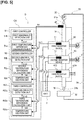
- the power conversion apparatus A illustrated in Figure 1 comprises a first inverter device (a power converter) 10 for driving a first power generation machine 1, and a second inverter device (a power converter) 20 for driving a second power generation machine 2.
- the first power generation machine 1 and the second power generation machine 2 are mounted in an electric vehicle, a hybrid vehicle, or the like, which is not shown.
- the purposes of the two power generation machines 1, 2 are not particularly limited.
- the two power generation machines 1, 2 can be used as drive sources for supplying driving force to drive wheels, which are not shown.
- one of the two power generation machines 1, 2 can be used as the drive source, and the other can be used as a generator for generating power by being driven by a drive source, such as an engine, which is not shown.
- the two inverter devices 10, 20 are mounted in a casing CA that houses the power conversion apparatus A.
- the first inverter device 10 converts a direct current, which is the electric power from a battery 3, to an alternating current, and supplies the alternating current to the first power generation machine 1, thereby driving the first power generation machine 1, or converts the alternating current generated by the first power generation machine 1 into a direct current, and supplies the direct current to the battery 3 for charging.
- the first inverter device 10 contains a smoothing capacitor and a power module, such as an IGBT module. Additionally, a secondary battery (lithium ion secondary battery, nickel hydrogen battery, or the like) having a voltage control range of about several hundred volts is employed as the battery 3.
- a secondary battery lithium ion secondary battery, nickel hydrogen battery, or the like having a voltage control range of about several hundred volts is employed as the battery 3.
- the second inverter device 20 also can convert a direct current from the battery 3 to an alternating current, and supply the alternating current to the second power generation machine 2, and also can convert the alternating current generated by the second power generation machine 2 into a direct current, and supply the direct current to the battery 3 for charging.
- this second inverter device 20 also contains a smoothing capacitor and a power module.
- first inverter device 10 and the second inverter device 20 respectively include a first inverter temperature sensor 11 and a second inverter temperature sensor 12, which detect the temperature of an internal heat-generating unit, such as a power module.
- the power conversion apparatus A comprises a cooling device 30.
- This cooling device 30 comprises a cooling water path 31, a radiator 32, a pump 33, and a circulation path 34, and cools the two inverter devices 10, 20 by circulating cooling water W.
- the cooling water path 31 is a flow path that is formed in the casing CA, and that runs from an inflow port 31a at a first end through the first inverter device 10 (the power converter of the preceding stage) and the second inverter device 20 (the power converter of the subsequent stage) in that order, and reaches an outflow port 31b at a second end.
- a circulation path 34 which is a flow path extending from the outflow port 31b to the inflow port 31a and provided with the radiator 32 and the pump 33 in the middle thereof, is connected to the cooling water path 31.
- the pump 33 circulates cooling water W by sucking the cooling water W from the outflow port 31b and pumping the cooling water to the inflow port 31a.
- the radiator 32 radiates the heat of the cooling water W to the outside air, thereby cooling the cooling water W.
- a water temperature sensor 40 is provided in the vicinity of the inflow port 31a, which is upstream from the first inverter device 10 in the cooling water path 31.
- Detection signals from this water temperature sensor 40 and the first inverter temperature sensor 11 and the second inverter temperature sensor 12 described above are input to a first controller 51 and a second controller 52.
- the first controller 51 detects a temperature abnormality of the first inverter device 10
- the second controller 52 detects a temperature abnormality of the second inverter device 20.
- the first controller 51 comprises a first temperature difference calculation unit 51a and a first abnormality detection unit 51b.
- the first abnormality detection unit 51b determines an abnormality when the first temperature difference ⁇ t1 is higher than a first abnormality determination temperature tlim1, and determines that there is no abnormality when the first temperature difference ⁇ t1 is equal to or less than the first abnormality determination temperature tlim1. That is, if an abnormality occurs in the cooling device 30, or an abnormality occurs in the first inverter device 10 and abnormal heat generation occurs, the first temperature difference ⁇ t1, which is the difference between the first inverter temperature tin1 and the cooling water temperature tw, increases. Therefore, the first abnormality determination temperature tlim1 is set to a value with which an occurrence of an abnormality can be determined, based on simulations, actual measurements at the time an abnormality occurs, and the like.
- the second controller 52 comprises a second temperature difference calculation unit 52a, a second abnormality detection unit 52b and a temperature addition unit 52c.
- the temperature addition unit 52c sets, as an addition value Tad, a value obtained by converting the loss in the first inverter device 10 during operation into a temperature increase of the cooling water temperature tw, and adds this value to the cooling water temperature tw detected by the water temperature sensor 40 to obtain an added temperature twa.
- the temperature increase due to this loss is set to the increase in the temperature of the cooling water temperature tw due to heat generation of the first inverter device 10 at the time of the maximum loss that is assumed in the first inverter device 10.
- An example of a time of maximum loss is when the first power generation machine 1 is in a locked state.
- a locked state is when the wheels of the vehicle are hitting a wheel stop or the like, and the vehicle cannot move forward even when attempting to move forward; that is, a case in which rotation does not occur in the first power generation machine 1, even though the first power generation machine 1 is being energized and driven.
- the temperature addition unit 52c calculates the addition value Tad from the command value and the cooling water temperature tw at the time the addition is carried out, and adds this value to the cooling water temperature tw to obtain the added temperature twa.
- the second temperature difference calculation unit 52a receives as inputs a second inverter temperature tin2 and the added temperature twa, and calculates a second temperature difference ⁇ t2, which is the difference between the two.
- the second abnormality detection unit 52b determines an abnormality when the second temperature difference ⁇ t2 is higher than a second abnormality determination temperature tlim2, and determines that there is no abnormality when the second temperature difference ⁇ t2 is equal to or less than the second abnormality determination temperature tlim2.
- This second abnormality determination temperature tlim2 is set in accordance with the second power generation machine 2 and the second inverter device 20, and is not necessarily the same value as the first abnormality determination temperature tlim1.
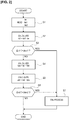
- a first inverter temperature tin1, a second inverter temperature tin2, and a cooling water temperature tw which are detected temperatures respectively from the first inverter temperature sensor 11, the second inverter temperature sensor 12, and the water temperature sensor 40, are read into the two controllers 51, 52.
- Step S2 the first temperature difference calculation unit 51a calculates a first temperature difference ⁇ t1, which is the difference between the first inverter temperature tin1 and the cooling water temperature tw, and the process proceeds to Step S3.
- Step S3 the presence of an abnormality in either the first inverter device 10 or the cooling system is determined by the first abnormality detection unit 51b, based on whether the first temperature difference ⁇ t1 is larger than the first abnormality determination temperature tlim1. If an abnormality is determined from ⁇ t1 > tlim1 the process proceeds to Step S7, and if it is determined that there is no abnormality (normal) from ⁇ t1 ⁇ tlim1 the process proceeds to Step S4.
- Step S4 to which the process proceeds when the first abnormality detection unit 51b determines that there is no abnormality (normal), the temperature addition unit 52c adds an addition value Tad corresponding to the loss component in the first inverter device 10 during operation to the cooling water temperature tw, thereby obtaining the added temperature twa, and the process proceeds to Step S5.
- Step S5 the second temperature difference calculation unit 52a calculates a second temperature difference ⁇ t2, which is the difference between the second inverter temperature tin2 and the added temperature twa, and the process proceeds to Step S6.
- Step S6 the presence of an abnormality in either the second inverter device 20 or the cooling system is determined by the second abnormality detection unit 52b, based on whether the second temperature difference ⁇ t2 is larger than the second abnormality determination temperature tlim2. If an abnormality is determined from ⁇ t2 > tlim2, the process proceeds to Step S7, and if it is determined that there is no abnormality (normal) from ⁇ t2 ⁇ tlim2, the first abnormality determination process is ended.
- Step S7 to which the process proceeds when an abnormality is determined in either Step S3 or Step S6, a preset fail process is executed.
- This fail process can be any process that suppresses heat generation in the two power generation machines 1, 2; for example, the process may be one whereby the output of one of the two power generation machines 1, 2 is suppressed by a predetermined amount or is stopped.
- each inverter device 10, 20 is cooled by the cooling device 30, and, accordingly the cooling water temperature tw in the cooling water path 31 is increased due to the heat generation of the first inverter device 10, and this increased cooling water temperature tw is further increased due to the heat generation of the second inverter device 20.
- This cooling water the temperature of which has increased is cooled by the radiation of heat by the radiator 32, and then is supplied again to the cooling water path 31.
- the abnormality determination of the second inverter device 20 is carried out based on the difference between the second inverter temperature tin2 and the cooling water temperature tw detected by the water temperature sensor 40, which is lower than the actual cooling water temperature of the second inverter device 20, this difference will be a value that is larger than the actual difference. Accordingly, the abnormality determination accuracy decreases, and the possibility that an abnormality will be erroneously determined and a fail process will be executed increases. That is, there is the risk that the abnormality detection accuracy will decrease, and that the operation range of the power conversion apparatus A will be reduced.
- an addition value Tad obtained by converting the loss component of the first inverter device 10 is used with the cooling water temperature tw detected by the water temperature sensor 40, for the abnormality determination for the second inverter device 20.
- the second temperature difference ( ⁇ t2) between the second inverter temperature tin2 and the cooling water temperature in the second inverter device 20 is more accurate than when the cooling water temperature tw detected by the water temperature sensor 40 is used as is, and the abnormality detection accuracy is improved.
- the detection of the water temperature is carried out only by a water temperature sensor 40 that is on the upstream side in the cooling water path 31, it is possible to suppress the cost compared to when a water temperature sensor is separately added in the power conversion apparatus A.
- an addition value Tad that is set in advance based on actual measurement values is used in the temperature addition unit 52c, the configuration of the temperature addition unit 52c of the second controller 52 can be simplified, and the cost can be reduced. Additionally, a value set based on the temperature due to the maximum loss assumed in the first inverter device 10 is used as the addition value Tad. Accordingly, the actual temperature increase of the cooling water W due to heat generation of the first inverter device 10 will not exceed the addition value Tad, so it is possible to prevent an erroneous determination in which is the device is determined to be normal even though an abnormality has occurred.
- the second embodiment is an example in which the method of converting the loss component of the first inverter device 10 into temperature and adding the same to the cooling water temperature tw is different from that of the first embodiment.
- a value calculated based on loss calculation information that includes semiconductor characteristics, the carrier frequency, and the current supplied to the first inverter device 10, is used as the temperature obtained by converting the loss component of the first inverter device 10.
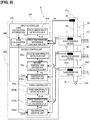
- Figure 3 is an overall view schematically illustrating a power conversion apparatus B to which the temperature abnormality detection method of the second embodiment is applied.
- an addition value calculated by a loss calculation unit 200 provided in the first controller 251 is used as the addition value, which is the temperature of the loss component.
- the loss calculation unit 200 calculates the addition value Tad based on loss calculation information that includes the semiconductor characteristics, the carrier frequency f, and the current I in the first inverter device 10.
- the first inverter device 10 comprises a well-known bridge-connected insulated gate bipolar transistor (hereinafter referred to as IGBT), and a diode (Free Wheeling Diode, hereinafter referred to as FWD).
- IGBT insulated gate bipolar transistor
- FWD Free Wheeling Diode
- the steady loss in the IGBT of the first inverter device 10 is calculated using the following formula (1), and the switching loss in the IGBT is calculated using the following formula (2).
- the steady loss in the FWD of the first inverter device 10 is calculated using the following formula (3), and the switching loss in the FWD is calculated using the following formula (4).
- the power module loss in the first inverter device 10 is then calculated from these values using the following formula (5).
- P Isat 1 2 ⁇ ⁇ 0 ⁇ Ic ⁇ sin x ⁇ Vce sat ⁇ sin x ⁇ 1 + D ⁇ sin x + ⁇ 2 dx
- P Isw Esw ⁇ f ⁇ 1 ⁇
- P Fsat 1 2 ⁇ ⁇ 0 ⁇ ⁇ Ic ⁇ sin x ⁇ ⁇ Vf ⁇ sin x ⁇ 1 + D ⁇ sin x + ⁇ 2 dx
- P Fsw Err ⁇ f ⁇ 1 2
- P PM P Isat + P Isw ⁇ N I + P Fsat + P Fsw ⁇ N F
- the loss in the first inverter device 10 obtained from the formulas above (power module loss P (PM)) is converted to temperature, and an addition value Tad corresponding to the temperature increase of the cooling water is calculated.
- This addition value Tad is obtained by repeatedly conducting experiments in advance, and using a table or a calculation formula that is set so as to be able to obtain the value in accordance with the power module loss P (PM) and the cooling water temperature tw.
- the temperature addition unit 252c adds the addition value Tad to the cooling water temperature tw detected by the water temperature sensor 40, and the calculation itself is the same as that of the temperature addition unit 52c shown in the first embodiment.
- a value that is closer to the temperature increase of the cooling water W due to heat generation caused by actual loss in the first inverter device 10 can be set as the addition value Tad, and therefore the abnormality detection accuracy is even higher.
- the temperature addition unit 252c uses, as the addition value Tad, which is the temperature obtained by converting the loss component to be added to the cooling water temperature tw, a value calculated based on loss calculation information that includes the number of FWD chips N(F), the number of IGBT chips N(l), a PWM modulation factor D as a semiconductor characteristic, a carrier frequency f, a current Ic and voltage Vce(sat) in the power module of the first inverter device 10.
- the addition value Tad can be obtained based on any one of the current Ic, the voltage Vce(sat), the semiconductor characteristic (carrier frequency f, PWM modulation factor D, number of IGBT chips N(1), and number of FWD chips N(F)).
- the third embodiment is an example in which the method of converting the loss component of the first inverter device 10 into temperature and adding the same to the cooling water temperature tw to obtain the addition value Tad is different from those of the first and second embodiments.
- a value estimated based on the first temperature difference ⁇ t1 between the temperature of the first inverter device 10 and the cooling water temperature tw is used as the addition value Tad that is added after the loss component of the first inverter device 10 is converted to temperature.
- Figure 4 is an overall view schematically illustrating a power conversion apparatus C to which the temperature abnormality detection method of the third embodiment is applied.
- the second temperature difference calculation unit 352a of the second controller 352 shown in Figure 4 calculates a second temperature difference ⁇ t2 between the added temperature twa3, estimated by a loss estimation unit 300, and the second inverter temperature tin2.
- the loss estimation unit 300 receives as an input the first temperature difference ⁇ t1 calculated by the first temperature difference calculation unit 51a, and back-calculates the loss in the first inverter device 10 from this first temperature difference ⁇ t1. Furthermore, the loss estimation unit 300 estimates an addition value corresponding to the temperature increase component of the cooling water due to this loss component, and calculates an added temperature twa3 obtained by adding this addition value to the cooling water temperature tw. As for this addition value, values corresponding to the first temperature difference ⁇ t1 and the driving state (for example, powering, regeneration, locking, etc.) of the first power generation machine 1 at that time are stored in the first controller 51 in the form of a map.
- the second temperature difference calculation unit 352a calculates a second temperature difference ⁇ t2 between this added temperature twa3 and the second inverter temperature tin2.
- the temperature increase of the cooling water corresponding to the estimated loss component of the first inverter device 10 is estimated based on the first temperature difference ⁇ t1.
- a value estimated based on a first temperature difference ⁇ t1, which is the difference between the first inverter temperature tin1, which is the temperature of the first inverter device 10, and the cooling water temperature tw, is used as the temperature of the loss component that is added in the second temperature difference calculation unit 352a.
- the heat generation state of the first inverter device 10 is estimated based on the difference between the first inverter temperature tin1 and the cooling water tw, thereby enabling the addition value to be obtained with high accuracy. Therefore, the cooling water temperature in the second inverter device 20 can be estimated with high accuracy based on this highly accurate addition value, and abnormality detection can be carried out with high accuracy on that basis.
- the power conversion apparatus D of the fourth embodiment is a modified example of the first embodiment and, as illustrated in Figure 5 , is an example in which a third inverter device 430 for driving a third power generation machine (not shown) is added in a subsequent stage of the cooling water path 31.
- a third controller 453, which carries out an abnormality determination for this third inverter device 430, comprises a third temperature difference calculation unit 453a, a third abnormality detection unit 453b, and a temperature addition unit 453c.
- the temperature addition unit 453c takes, as an addition value Tad, a value obtained by converting the loss in the first inverter device 10 during operation and the loss in the second inverter device 20 during operation into a temperature increase of the cooling water temperature tw, and adds this value to the cooling water temperature tw detected by the water temperature sensor 40 to obtain an added temperature twb.
- the temperature increase due to this loss is set to the increase in the temperature of the cooling water temperature tw due to heat generation at the time of the maximum loss assumed in the two inverter devices 10, 20.
- the third temperature difference calculation unit 453a then receives as inputs a third inverter temperature tin3 detected by the third inverter temperature sensor 413, and the added temperature twb, and calculates a third temperature difference ⁇ t3, which is the difference between the two.
- the third abnormality detection unit 453b determines an abnormality when the third temperature difference ⁇ t3 is higher than a third abnormality determination temperature (tlim3), and determines that there is no abnormality when the third temperature difference ⁇ t3 is equal to or less than the third abnormality determination temperature (tlim3).
- This third abnormality determination temperature tlim3 is set in accordance with a third rotary electric machine (not shown) and the third inverter device 430.
- the effects 1) to 3) described in the first embodiment can be obtained even if the number of inverter devices increases.
- the power conversion apparatus E of the fifth embodiment is a modified example of the second embodiment and, as illustrated in Figure 6 , is an example in which a third inverter device 530 is added in a subsequent stage of the cooling water path 31, in the same manner as the fourth embodiment described above.
- an addition value Tad2 calculated by a loss calculation unit 500 provided in the first controller 251 is used as the addition value, which is the temperature of the loss component.
- the loss calculation unit 500 calculates the addition value Tad based on loss calculation information that includes the semiconductor characteristics, the carrier frequency f, and the current I in the first inverter device 10, in the same manner as the second embodiment. In addition, the loss calculation unit 500 calculates the addition value Tad2 based on loss calculation information that includes the semiconductor characteristics, the carrier frequency f, and the current I in the second inverter device 20.
- this addition value Tad2 can be carried out using a table or a calculation formula in the same manner as in the second embodiment.
- the addition values Tad, Tad2 can be calculated based on any one of the current I, the carrier frequency f, and the semiconductor characteristics.
- the third temperature difference calculation unit 553a then receives as inputs a third inverter temperature tin3 detected by the third inverter temperature sensor 513 and the added temperature twb calculated using the addition value Tad2, and calculates a third temperature difference ⁇ t3, which is the difference between the two.
- the third abnormality detection unit 553b determines an abnormality when the third temperature difference ⁇ t3 is higher than a third abnormality determination temperature (tlim3), and determines that there is no abnormality when the third temperature difference ⁇ t3 is equal to or less than the third abnormality determination temperature (tlim3).
- the effect described in 2-1) above can be obtained even if the number of inverter devices increases.
- the added temperature twb can be calculated using the same method as in the third embodiment when detecting an abnormality of the third inverter device. That is, in this case a value estimated based on the second temperature difference ⁇ t2 in the second inverter device 20 is used as the temperature of the loss component to be added in the third temperature difference calculation unit.
- the temperature abnormality detection method for a power conversion apparatus and the temperature abnormality detection device for a power conversion apparatus of the present invention were described above based on embodiments, but specific configurations thereof are not limited to these embodiments, and various modifications and additions to the design can be made without departing from the scope of the invention according to each claim in the Claims.
- inverter devices were shown as the plurality of power converters for converting and transmitting electric power, but the power converters are not limited to inverter devices; other power converters such as converters may be used as well. Accordingly, in the embodiments a power generation machine was shown as the output target of the power converters, but the output target is not limited thereto, and other devices, such as a battery, can be used.
- cooling water was shown as the coolant that flows through the cooling flow path, but the coolant is not limited thereto; gas or fluids other than water may be used.
- the temperature increase of the water temperature at the time of maximum loss assumed in the first inverter device was set as the temperature to which the temperature of the loss component of the power converter of the preceding stage is added, but no limitation is imposed thereby.
- it may be set as the temperature increase of the water temperature at the time of maximum loss in the driving state of the first power generation machine, in accordance with that driving state. That is, it may be set as the temperature increase at the time of maximum loss for each driving state, such a powering, regeneration, and locked.
- the temperature increase of the loss component is obtained based on formulas (1) to (5); however, it is not limited to the formulas (1) to (5), as long as the value is calculated based on loss calculation information that includes the semiconductor characteristics, the carrier frequency, and the current supplied to the power converter.
- the number of power converters is not limited to “2" and "3" illustrated in the embodiments; four or more can be provided.
Landscapes
- Engineering & Computer Science (AREA)
- Physics & Mathematics (AREA)
- Power Engineering (AREA)
- General Physics & Mathematics (AREA)
- Microelectronics & Electronic Packaging (AREA)
- Thermal Sciences (AREA)
- Inverter Devices (AREA)
- Measuring Temperature Or Quantity Of Heat (AREA)
- Power Conversion In General (AREA)
- Rectifiers (AREA)
Claims (6)
- Verfahren zum Erfassen einer Temperaturanomalie für eine Stromrichtervorrichtung, die mit mehreren Stromrichtern (10, 20), die elektrischen Strom umrichten und übertragen, und einem Kühlungsströmungsweg (31) versehen ist, der durch die mehreren Stromrichter geht und jeden der Stromrichter kühlt, wobei das Verfahren aufweist:Erfassen von Temperaturen der Stromrichter und Erfassen einer Temperatur eines Kühlfluids des Kühlungsströmungswegs auf einer Stromaufwärtsseite der Stromrichter;gekennzeichnet durchFeststellen eines Vorhandenseins einer Anomalie in einem Stromrichter (10) einer vorhergehenden Stufe, der im Kühlungsströmungsweg stromaufwärts angeordnet ist, unter den mehreren Stromrichtern beruhend auf einer Differenz (Δt1) zwischen einer Temperatur (tin1) des Stromrichters (10) der vorhergehenden Stufe und der Temperatur (tw) des Kühlfluids; undFeststellen eines Vorhandenseins einer Anomalie in einem Stromrichter (20) einer nachfolgenden Stufe, der stromabwärts vom Stromrichter (10) der vorhergehenden Stufe im Kühlungsströmungsweg angeordnet ist, beruhend auf einer Differenz (Δt2) zwischen der Temperatur (tin2) des Stromrichters (20) der nachfolgenden Stufe und einer Temperatur (twa), die durch Umwandeln einer Verlustkomponente des Stromrichters der vorhergehenden Stufe in eine Temperatur (Tad) erhalten wird, die zur Temperatur (tw) des Kühlfluids addiert wird.
- Verfahren zum Erfassen einer Temperaturanomalie für eine Stromrichtervorrichtung nach Anspruch 1, wobei die Temperatur (Tad), die durch Umwandeln der Verlustkomponente erhalten wird, auf einen Wert eingestellt wird, der auf einer Temperatur beruht, die aus einem Maximalverlust umgewandelt wird, der im Stromrichter der vorhergehenden Stufe angenommen wird.
- Verfahren zum Erfassen einer Temperaturanomalie für eine Stromrichtervorrichtung nach Anspruch 1, wobei die Temperatur (Tad), die durch Umwandeln der Verlustkomponente erhalten wird, auf einen Wert eingestellt wird, der beruhend auf Verlustberechnungsinformationen berechnet wird, die Halbleitereigenschaften und/oder eine Trägerfrequenz und/oder den Strom im Stromrichter der vorhergehenden Stufe enthalten.
- Verfahren zum Erfassen einer Temperaturanomalie für eine Stromrichtervorrichtung nach Anspruch 1, wobei die Temperatur (Tad), die durch Umwandeln der Verlustkomponente erhalten wird, auf einen Wert eingestellt wird, der beruhend auf der Differenz (Δt1) zwischen der Temperatur (tin1) des Stromrichters der vorhergehenden Stufe und der Temperatur des Kühlfluids (tw) geschätzt wird.
- Verfahren zum Erfassen einer Temperaturanomalie für eine Stromrichtervorrichtung nach einem der Ansprüche 1 bis 4, wobei
ein Wert, der auf der Temperatur infolge des Maximalverlusts beruht, der im Stromrichter (10) der vorhergehenden Stufe angenommen wird, als die Temperatur (Tad) verwendet wird, die zur Temperatur (tw) des Kühlfluids addiert wird. - Vorrichtung zur Erfassung einer Temperaturanomalie für eine Stromrichtervorrichtung, mit:mehreren Stromrichtern (10, 20), die konfiguriert sind, elektrischen Strom umzurichten und zu übertragen;einem Kühlungsströmungsweg (30), der durch die mehreren Stromrichter geht und jeden der Stromrichter kühlt;Stromrichter-Temperatursensoren (11, 12), die konfiguriert sind, Temperaturen der mehreren Stromrichter zu erfassen;einem Kühlfluid-Temperatursensor (40), der konfiguriert ist, eine Temperatur eines Kühlfluids des Kühlungsströmungswegs zu erfassen, der stromaufwärts von den mehreren Stromrichtern liegt;gekennzeichnet durcheine Einheit (51) zur Berechnung einer Temperaturdifferenz der vorhergehenden Stufe, die konfiguriert ist, eine Differenz (Δt1) zwischen einer Kühlfluidtemperatur (tw) und einer Temperatur (tin1) eines Stromrichters (10) einer vorhergehenden Stufe zu berechnen, der im Kühlungsströmungsweg stromaufwärts angeordnet ist;eine Einheit (51b) zur Erfassung einer Anomalie eines Stromrichters der vorhergehenden Stufe, die konfiguriert ist, eine Anomaliefeststellung beruhend auf der Differenz (Δt1) auszuführen, die durch die Einheit (51) zur Berechnung einer Temperaturdifferenz der vorhergehenden Stufe berechnet wird;eine Temperaturadditionseinheit (52c), die konfiguriert ist, eine Verlustkomponente des Stromrichters (10) der vorhergehenden Stufe in eine Temperatur (Tad) umzuwandeln und dieselbe (Tad) zur Kühlfluidtemperatur (tw) zu addieren;eine Einheit (52a) zur Berechnung einer Temperaturdifferenz der nachfolgenden Stufe, die konfiguriert ist, eine Differenz (Δt2) zwischen der durch die Temperaturadditionseinheit (52c) berechneten Temperatur (twa) und einer Temperatur (tin2) eines Stromrichters (20) der nachfolgenden Stufe zu berechnen, der stromabwärts vom Stromrichter (10) der vorhergehenden Stufe im Kühlungsströmungsweg angeordnet ist; undeine Einheit (52b) zur Erfassung einer Anomalie eines Stromrichters der nachfolgenden Stufe, die konfiguriert ist, eine Anomaliefeststellung beruhend auf der Differenz (Δt2) auszuführen, die durch die Einheit (52a) zur Berechnung einer Temperaturdifferenz der nachfolgenden Stufe berechnet wird.
Applications Claiming Priority (1)
| Application Number | Priority Date | Filing Date | Title |
|---|---|---|---|
| PCT/JP2016/065728 WO2017203693A1 (ja) | 2016-05-27 | 2016-05-27 | 電力変換装置の温度異常検出方法および電力変換装置の温度異常検出装置 |
Publications (3)
| Publication Number | Publication Date |
|---|---|
| EP3468018A4 EP3468018A4 (de) | 2019-04-10 |
| EP3468018A1 EP3468018A1 (de) | 2019-04-10 |
| EP3468018B1 true EP3468018B1 (de) | 2020-10-07 |
Family
ID=60411795
Family Applications (1)
| Application Number | Title | Priority Date | Filing Date |
|---|---|---|---|
| EP16903174.7A Active EP3468018B1 (de) | 2016-05-27 | 2016-05-27 | Verfahren zur erkennung von temperaturanomalien bei einer leistungsumwandlungsvorrichtung und vorrichtung zur erkennung von temperaturanomalien bei einer leistungsumwandlungsvorrichtung |
Country Status (10)
| Country | Link |
|---|---|
| US (1) | US10739207B2 (de) |
| EP (1) | EP3468018B1 (de) |
| JP (1) | JP6402841B2 (de) |
| KR (1) | KR101973926B1 (de) |
| CN (1) | CN109275350B (de) |
| BR (1) | BR112018074335B1 (de) |
| CA (1) | CA3025638C (de) |
| MX (1) | MX378917B (de) |
| RU (1) | RU2697050C1 (de) |
| WO (1) | WO2017203693A1 (de) |
Families Citing this family (12)
| Publication number | Priority date | Publication date | Assignee | Title |
|---|---|---|---|---|
| EP3780374A4 (de) * | 2018-04-11 | 2021-04-07 | Nissan Motor Co., Ltd. | Maschinenschutzvorrichtung und maschinenschutzverfahren |
| CN109830941A (zh) * | 2019-03-04 | 2019-05-31 | 苏州弈力能源科技有限公司 | 新能源汽车igbt模组过温保护策略和装置 |
| KR102666376B1 (ko) * | 2019-06-14 | 2024-05-17 | 현대모비스 주식회사 | 차량용 제동장치 |
| CN110412369A (zh) * | 2019-07-11 | 2019-11-05 | 南方电网科学研究院有限责任公司 | 一种柔性直流换流阀功率模块损耗测量系统 |
| JP7380187B2 (ja) * | 2019-12-24 | 2023-11-15 | 株式会社デンソー | 電力変換装置 |
| JP7494041B2 (ja) * | 2020-07-29 | 2024-06-03 | 株式会社日立産機システム | 電力変換装置および遠隔監視システム |
| US11835550B2 (en) * | 2021-08-11 | 2023-12-05 | Infineon Technologies Austria Ag | Power conversion, fault management, and notification |
| JP7533498B2 (ja) * | 2022-02-09 | 2024-08-14 | トヨタ自動車株式会社 | 冷却システムの制御装置 |
| CN115468628A (zh) * | 2022-07-22 | 2022-12-13 | 大庆飞海石油科技有限公司 | 一种油田用带隔离保护结构的液位计 |
| US12282368B2 (en) * | 2022-10-25 | 2025-04-22 | Dell Products L.P. | Fault identification of multiple phase voltage regulator |
| JP2024093978A (ja) * | 2022-12-27 | 2024-07-09 | 株式会社日立製作所 | 電力変換装置 |
| JP2024151081A (ja) * | 2023-04-11 | 2024-10-24 | トヨタ自動車株式会社 | 冷却装置 |
Family Cites Families (17)
| Publication number | Priority date | Publication date | Assignee | Title |
|---|---|---|---|---|
| JP3918736B2 (ja) * | 2003-01-16 | 2007-05-23 | トヨタ自動車株式会社 | 電圧変換装置 |
| JP3963175B2 (ja) * | 2004-03-19 | 2007-08-22 | 日産自動車株式会社 | 温度検出装置および温度検出用プログラム |
| JP2006238675A (ja) * | 2005-02-28 | 2006-09-07 | Tdk Corp | 電力変換装置及び電力変換装置への過熱保護温度設定方法 |
| JP4694278B2 (ja) * | 2005-04-28 | 2011-06-08 | 本田技研工業株式会社 | バッテリユニット構造 |
| JP4349447B2 (ja) | 2007-07-19 | 2009-10-21 | トヨタ自動車株式会社 | インバータ制御装置および車両 |
| JP5092696B2 (ja) * | 2007-11-06 | 2012-12-05 | 株式会社デンソー | 冷却流体の温度情報取得装置 |
| JP5077162B2 (ja) | 2008-09-11 | 2012-11-21 | トヨタ自動車株式会社 | 駆動装置およびその制御方法並びに車両 |
| JP2010136472A (ja) * | 2008-12-02 | 2010-06-17 | Toyota Motor Corp | 回転電機駆動制御装置及びその制御方法 |
| JP5378264B2 (ja) | 2010-02-19 | 2013-12-25 | 富士重工業株式会社 | 電気自動車のインバータ冷却装置 |
| JP2012044772A (ja) * | 2010-08-18 | 2012-03-01 | Toyota Motor Corp | 車両のインバータ冷却制御装置 |
| JP5516272B2 (ja) * | 2010-09-22 | 2014-06-11 | トヨタ自動車株式会社 | 回転電機制御システム |
| CN102253320B (zh) | 2011-04-19 | 2013-06-05 | 南车株洲电力机车研究所有限公司 | 一种igbt失效预警方法 |
| JP5927082B2 (ja) * | 2012-08-28 | 2016-05-25 | 本田技研工業株式会社 | 電動機の駆動装置 |
| JP5907236B2 (ja) * | 2013-12-11 | 2016-04-26 | 株式会社デンソー | 温度検出装置 |
| RU2549255C1 (ru) * | 2014-12-18 | 2015-04-20 | Морской гидрофизический институт | Цифровой измеритель температуры |
| KR20170097421A (ko) * | 2016-02-18 | 2017-08-28 | 엘에스산전 주식회사 | 2차원 배열 전력변환장치용 냉각 시스템 |
| CN109792218B (zh) * | 2016-08-23 | 2020-04-07 | 日产自动车株式会社 | 电力变换装置的温度异常检测方法和温度异常检测装置 |
-
2016
- 2016-05-27 EP EP16903174.7A patent/EP3468018B1/de active Active
- 2016-05-27 CN CN201680086022.1A patent/CN109275350B/zh active Active
- 2016-05-27 JP JP2018518918A patent/JP6402841B2/ja active Active
- 2016-05-27 US US16/302,761 patent/US10739207B2/en active Active
- 2016-05-27 WO PCT/JP2016/065728 patent/WO2017203693A1/ja not_active Ceased
- 2016-05-27 KR KR1020187035690A patent/KR101973926B1/ko not_active Expired - Fee Related
- 2016-05-27 MX MX2018014352A patent/MX378917B/es unknown
- 2016-05-27 BR BR112018074335-6A patent/BR112018074335B1/pt not_active IP Right Cessation
- 2016-05-27 RU RU2018146439A patent/RU2697050C1/ru active
- 2016-05-27 CA CA3025638A patent/CA3025638C/en active Active
Non-Patent Citations (1)
| Title |
|---|
| None * |
Also Published As
| Publication number | Publication date |
|---|---|
| US10739207B2 (en) | 2020-08-11 |
| KR101973926B1 (ko) | 2019-04-29 |
| MX378917B (es) | 2025-03-10 |
| EP3468018A4 (de) | 2019-04-10 |
| US20200182706A1 (en) | 2020-06-11 |
| WO2017203693A1 (ja) | 2017-11-30 |
| CN109275350A (zh) | 2019-01-25 |
| JPWO2017203693A1 (ja) | 2018-09-27 |
| KR20180136564A (ko) | 2018-12-24 |
| CN109275350B (zh) | 2020-12-15 |
| MX2018014352A (es) | 2019-03-14 |
| BR112018074335A2 (pt) | 2019-03-06 |
| BR112018074335B1 (pt) | 2022-11-08 |
| CA3025638C (en) | 2020-08-25 |
| CA3025638A1 (en) | 2017-11-30 |
| JP6402841B2 (ja) | 2018-10-10 |
| EP3468018A1 (de) | 2019-04-10 |
| RU2697050C1 (ru) | 2019-08-09 |
Similar Documents
| Publication | Publication Date | Title |
|---|---|---|
| EP3468018A1 (de) | Verfahren zur erkennung von temperaturanomalien bei einer leistungsumwandlungsvorrichtung und vorrichtung zur erkennung von temperaturanomalien bei einer leistungsumwandlungsvorrichtung | |
| EP3506482B1 (de) | Verfahren zum erfassen von temperaturabweichungen für eine leistungsumwandlungsvorrichtung und vorrichtung zum erfassen von temperaturabweichungen für eine leistungsumwandlungsvorrichtung | |
| US9768668B2 (en) | Cooling system of power converter for on-vehicle rotary electric machine | |
| EP3041126B1 (de) | Vorrichtung zur bestimmung von sensoranomalien | |
| CN102474198B (zh) | 逆变器装置 | |
| US11025157B2 (en) | Control circuit, electric driving system, inverter system and method for controlling thereof | |
| JP2012170211A (ja) | 異常判定装置、異常素子検出装置および車両駆動システム | |
| JP6299368B2 (ja) | 半導体素子温度推定装置 | |
| JP2020071093A (ja) | 電流センサ | |
| KR20180055052A (ko) | 스위칭 소자 온도 추정 시스템 및 방법 | |
| JP6119647B2 (ja) | 電動車両 | |
| JP2020088872A (ja) | 電気自動車用の電力変換装置 | |
| JP5516272B2 (ja) | 回転電機制御システム | |
| US20250211069A1 (en) | Control device | |
| US20250251292A1 (en) | Temperature estimation system and temperature estimation method | |
| JP2024168140A (ja) | インバータのパワーデバイス温度推定装置 | |
| CN116707390A (zh) | 功率转换装置及其温度推算方法 | |
| JP2001238301A (ja) | 電気エネルギの損失測定装置および損失測定方法 |
Legal Events
| Date | Code | Title | Description |
|---|---|---|---|
| STAA | Information on the status of an ep patent application or granted ep patent |
Free format text: STATUS: THE INTERNATIONAL PUBLICATION HAS BEEN MADE |
|
| PUAI | Public reference made under article 153(3) epc to a published international application that has entered the european phase |
Free format text: ORIGINAL CODE: 0009012 |
|
| STAA | Information on the status of an ep patent application or granted ep patent |
Free format text: STATUS: REQUEST FOR EXAMINATION WAS MADE |
|
| 17P | Request for examination filed |
Effective date: 20181218 |
|
| A4 | Supplementary search report drawn up and despatched |
Effective date: 20190211 |
|
| AK | Designated contracting states |
Kind code of ref document: A1 Designated state(s): AL AT BE BG CH CY CZ DE DK EE ES FI FR GB GR HR HU IE IS IT LI LT LU LV MC MK MT NL NO PL PT RO RS SE SI SK SM TR |
|
| AX | Request for extension of the european patent |
Extension state: BA ME |
|
| DAV | Request for validation of the european patent (deleted) | ||
| DAX | Request for extension of the european patent (deleted) | ||
| GRAP | Despatch of communication of intention to grant a patent |
Free format text: ORIGINAL CODE: EPIDOSNIGR1 |
|
| STAA | Information on the status of an ep patent application or granted ep patent |
Free format text: STATUS: GRANT OF PATENT IS INTENDED |
|
| INTG | Intention to grant announced |
Effective date: 20200519 |
|
| GRAJ | Information related to disapproval of communication of intention to grant by the applicant or resumption of examination proceedings by the epo deleted |
Free format text: ORIGINAL CODE: EPIDOSDIGR1 |
|
| STAA | Information on the status of an ep patent application or granted ep patent |
Free format text: STATUS: REQUEST FOR EXAMINATION WAS MADE |
|
| GRAR | Information related to intention to grant a patent recorded |
Free format text: ORIGINAL CODE: EPIDOSNIGR71 |
|
| GRAS | Grant fee paid |
Free format text: ORIGINAL CODE: EPIDOSNIGR3 |
|
| STAA | Information on the status of an ep patent application or granted ep patent |
Free format text: STATUS: GRANT OF PATENT IS INTENDED |
|
| INTC | Intention to grant announced (deleted) | ||
| GRAA | (expected) grant |
Free format text: ORIGINAL CODE: 0009210 |
|
| STAA | Information on the status of an ep patent application or granted ep patent |
Free format text: STATUS: THE PATENT HAS BEEN GRANTED |
|
| INTG | Intention to grant announced |
Effective date: 20200827 |
|
| AK | Designated contracting states |
Kind code of ref document: B1 Designated state(s): AL AT BE BG CH CY CZ DE DK EE ES FI FR GB GR HR HU IE IS IT LI LT LU LV MC MK MT NL NO PL PT RO RS SE SI SK SM TR |
|
| REG | Reference to a national code |
Ref country code: GB Ref legal event code: FG4D |
|
| REG | Reference to a national code |
Ref country code: CH Ref legal event code: EP Ref country code: AT Ref legal event code: REF Ref document number: 1322222 Country of ref document: AT Kind code of ref document: T Effective date: 20201015 |
|
| REG | Reference to a national code |
Ref country code: DE Ref legal event code: R096 Ref document number: 602016045642 Country of ref document: DE |
|
| REG | Reference to a national code |
Ref country code: IE Ref legal event code: FG4D |
|
| REG | Reference to a national code |
Ref country code: NL Ref legal event code: MP Effective date: 20201007 |
|
| REG | Reference to a national code |
Ref country code: AT Ref legal event code: MK05 Ref document number: 1322222 Country of ref document: AT Kind code of ref document: T Effective date: 20201007 |
|
| PG25 | Lapsed in a contracting state [announced via postgrant information from national office to epo] |
Ref country code: FI Free format text: LAPSE BECAUSE OF FAILURE TO SUBMIT A TRANSLATION OF THE DESCRIPTION OR TO PAY THE FEE WITHIN THE PRESCRIBED TIME-LIMIT Effective date: 20201007 Ref country code: GR Free format text: LAPSE BECAUSE OF FAILURE TO SUBMIT A TRANSLATION OF THE DESCRIPTION OR TO PAY THE FEE WITHIN THE PRESCRIBED TIME-LIMIT Effective date: 20210108 Ref country code: PT Free format text: LAPSE BECAUSE OF FAILURE TO SUBMIT A TRANSLATION OF THE DESCRIPTION OR TO PAY THE FEE WITHIN THE PRESCRIBED TIME-LIMIT Effective date: 20210208 Ref country code: RS Free format text: LAPSE BECAUSE OF FAILURE TO SUBMIT A TRANSLATION OF THE DESCRIPTION OR TO PAY THE FEE WITHIN THE PRESCRIBED TIME-LIMIT Effective date: 20201007 Ref country code: NO Free format text: LAPSE BECAUSE OF FAILURE TO SUBMIT A TRANSLATION OF THE DESCRIPTION OR TO PAY THE FEE WITHIN THE PRESCRIBED TIME-LIMIT Effective date: 20210107 |
|
| REG | Reference to a national code |
Ref country code: LT Ref legal event code: MG4D |
|
| PG25 | Lapsed in a contracting state [announced via postgrant information from national office to epo] |
Ref country code: AT Free format text: LAPSE BECAUSE OF FAILURE TO SUBMIT A TRANSLATION OF THE DESCRIPTION OR TO PAY THE FEE WITHIN THE PRESCRIBED TIME-LIMIT Effective date: 20201007 Ref country code: ES Free format text: LAPSE BECAUSE OF FAILURE TO SUBMIT A TRANSLATION OF THE DESCRIPTION OR TO PAY THE FEE WITHIN THE PRESCRIBED TIME-LIMIT Effective date: 20201007 Ref country code: BG Free format text: LAPSE BECAUSE OF FAILURE TO SUBMIT A TRANSLATION OF THE DESCRIPTION OR TO PAY THE FEE WITHIN THE PRESCRIBED TIME-LIMIT Effective date: 20210107 Ref country code: PL Free format text: LAPSE BECAUSE OF FAILURE TO SUBMIT A TRANSLATION OF THE DESCRIPTION OR TO PAY THE FEE WITHIN THE PRESCRIBED TIME-LIMIT Effective date: 20201007 Ref country code: IS Free format text: LAPSE BECAUSE OF FAILURE TO SUBMIT A TRANSLATION OF THE DESCRIPTION OR TO PAY THE FEE WITHIN THE PRESCRIBED TIME-LIMIT Effective date: 20210207 Ref country code: LV Free format text: LAPSE BECAUSE OF FAILURE TO SUBMIT A TRANSLATION OF THE DESCRIPTION OR TO PAY THE FEE WITHIN THE PRESCRIBED TIME-LIMIT Effective date: 20201007 Ref country code: SE Free format text: LAPSE BECAUSE OF FAILURE TO SUBMIT A TRANSLATION OF THE DESCRIPTION OR TO PAY THE FEE WITHIN THE PRESCRIBED TIME-LIMIT Effective date: 20201007 |
|
| PG25 | Lapsed in a contracting state [announced via postgrant information from national office to epo] |
Ref country code: HR Free format text: LAPSE BECAUSE OF FAILURE TO SUBMIT A TRANSLATION OF THE DESCRIPTION OR TO PAY THE FEE WITHIN THE PRESCRIBED TIME-LIMIT Effective date: 20201007 Ref country code: NL Free format text: LAPSE BECAUSE OF FAILURE TO SUBMIT A TRANSLATION OF THE DESCRIPTION OR TO PAY THE FEE WITHIN THE PRESCRIBED TIME-LIMIT Effective date: 20201007 |
|
| REG | Reference to a national code |
Ref country code: DE Ref legal event code: R097 Ref document number: 602016045642 Country of ref document: DE |
|
| PG25 | Lapsed in a contracting state [announced via postgrant information from national office to epo] |
Ref country code: EE Free format text: LAPSE BECAUSE OF FAILURE TO SUBMIT A TRANSLATION OF THE DESCRIPTION OR TO PAY THE FEE WITHIN THE PRESCRIBED TIME-LIMIT Effective date: 20201007 Ref country code: CZ Free format text: LAPSE BECAUSE OF FAILURE TO SUBMIT A TRANSLATION OF THE DESCRIPTION OR TO PAY THE FEE WITHIN THE PRESCRIBED TIME-LIMIT Effective date: 20201007 Ref country code: LT Free format text: LAPSE BECAUSE OF FAILURE TO SUBMIT A TRANSLATION OF THE DESCRIPTION OR TO PAY THE FEE WITHIN THE PRESCRIBED TIME-LIMIT Effective date: 20201007 Ref country code: SM Free format text: LAPSE BECAUSE OF FAILURE TO SUBMIT A TRANSLATION OF THE DESCRIPTION OR TO PAY THE FEE WITHIN THE PRESCRIBED TIME-LIMIT Effective date: 20201007 Ref country code: RO Free format text: LAPSE BECAUSE OF FAILURE TO SUBMIT A TRANSLATION OF THE DESCRIPTION OR TO PAY THE FEE WITHIN THE PRESCRIBED TIME-LIMIT Effective date: 20201007 Ref country code: SK Free format text: LAPSE BECAUSE OF FAILURE TO SUBMIT A TRANSLATION OF THE DESCRIPTION OR TO PAY THE FEE WITHIN THE PRESCRIBED TIME-LIMIT Effective date: 20201007 |
|
| PLBE | No opposition filed within time limit |
Free format text: ORIGINAL CODE: 0009261 |
|
| STAA | Information on the status of an ep patent application or granted ep patent |
Free format text: STATUS: NO OPPOSITION FILED WITHIN TIME LIMIT |
|
| PG25 | Lapsed in a contracting state [announced via postgrant information from national office to epo] |
Ref country code: DK Free format text: LAPSE BECAUSE OF FAILURE TO SUBMIT A TRANSLATION OF THE DESCRIPTION OR TO PAY THE FEE WITHIN THE PRESCRIBED TIME-LIMIT Effective date: 20201007 |
|
| 26N | No opposition filed |
Effective date: 20210708 |
|
| PG25 | Lapsed in a contracting state [announced via postgrant information from national office to epo] |
Ref country code: IT Free format text: LAPSE BECAUSE OF FAILURE TO SUBMIT A TRANSLATION OF THE DESCRIPTION OR TO PAY THE FEE WITHIN THE PRESCRIBED TIME-LIMIT Effective date: 20201007 Ref country code: AL Free format text: LAPSE BECAUSE OF FAILURE TO SUBMIT A TRANSLATION OF THE DESCRIPTION OR TO PAY THE FEE WITHIN THE PRESCRIBED TIME-LIMIT Effective date: 20201007 |
|
| PG25 | Lapsed in a contracting state [announced via postgrant information from national office to epo] |
Ref country code: SI Free format text: LAPSE BECAUSE OF FAILURE TO SUBMIT A TRANSLATION OF THE DESCRIPTION OR TO PAY THE FEE WITHIN THE PRESCRIBED TIME-LIMIT Effective date: 20201007 |
|
| REG | Reference to a national code |
Ref country code: CH Ref legal event code: PL |
|
| PG25 | Lapsed in a contracting state [announced via postgrant information from national office to epo] |
Ref country code: CH Free format text: LAPSE BECAUSE OF NON-PAYMENT OF DUE FEES Effective date: 20210531 Ref country code: LU Free format text: LAPSE BECAUSE OF NON-PAYMENT OF DUE FEES Effective date: 20210527 Ref country code: LI Free format text: LAPSE BECAUSE OF NON-PAYMENT OF DUE FEES Effective date: 20210531 Ref country code: MC Free format text: LAPSE BECAUSE OF FAILURE TO SUBMIT A TRANSLATION OF THE DESCRIPTION OR TO PAY THE FEE WITHIN THE PRESCRIBED TIME-LIMIT Effective date: 20201007 |
|
| REG | Reference to a national code |
Ref country code: BE Ref legal event code: MM Effective date: 20210531 |
|
| PG25 | Lapsed in a contracting state [announced via postgrant information from national office to epo] |
Ref country code: IE Free format text: LAPSE BECAUSE OF NON-PAYMENT OF DUE FEES Effective date: 20210527 |
|
| PG25 | Lapsed in a contracting state [announced via postgrant information from national office to epo] |
Ref country code: IS Free format text: LAPSE BECAUSE OF FAILURE TO SUBMIT A TRANSLATION OF THE DESCRIPTION OR TO PAY THE FEE WITHIN THE PRESCRIBED TIME-LIMIT Effective date: 20210207 |
|
| PG25 | Lapsed in a contracting state [announced via postgrant information from national office to epo] |
Ref country code: BE Free format text: LAPSE BECAUSE OF NON-PAYMENT OF DUE FEES Effective date: 20210531 |
|
| PG25 | Lapsed in a contracting state [announced via postgrant information from national office to epo] |
Ref country code: CY Free format text: LAPSE BECAUSE OF FAILURE TO SUBMIT A TRANSLATION OF THE DESCRIPTION OR TO PAY THE FEE WITHIN THE PRESCRIBED TIME-LIMIT Effective date: 20201007 |
|
| PG25 | Lapsed in a contracting state [announced via postgrant information from national office to epo] |
Ref country code: HU Free format text: LAPSE BECAUSE OF FAILURE TO SUBMIT A TRANSLATION OF THE DESCRIPTION OR TO PAY THE FEE WITHIN THE PRESCRIBED TIME-LIMIT; INVALID AB INITIO Effective date: 20160527 |
|
| PG25 | Lapsed in a contracting state [announced via postgrant information from national office to epo] |
Ref country code: MK Free format text: LAPSE BECAUSE OF FAILURE TO SUBMIT A TRANSLATION OF THE DESCRIPTION OR TO PAY THE FEE WITHIN THE PRESCRIBED TIME-LIMIT Effective date: 20201007 |
|
| PG25 | Lapsed in a contracting state [announced via postgrant information from national office to epo] |
Ref country code: MT Free format text: LAPSE BECAUSE OF FAILURE TO SUBMIT A TRANSLATION OF THE DESCRIPTION OR TO PAY THE FEE WITHIN THE PRESCRIBED TIME-LIMIT Effective date: 20201007 |
|
| PGFP | Annual fee paid to national office [announced via postgrant information from national office to epo] |
Ref country code: DE Payment date: 20250423 Year of fee payment: 10 |
|
| PGFP | Annual fee paid to national office [announced via postgrant information from national office to epo] |
Ref country code: FR Payment date: 20250424 Year of fee payment: 10 |
|
| PG25 | Lapsed in a contracting state [announced via postgrant information from national office to epo] |
Ref country code: TR Free format text: LAPSE BECAUSE OF FAILURE TO SUBMIT A TRANSLATION OF THE DESCRIPTION OR TO PAY THE FEE WITHIN THE PRESCRIBED TIME-LIMIT Effective date: 20201007 |
|
| PGFP | Annual fee paid to national office [announced via postgrant information from national office to epo] |
Ref country code: GB Payment date: 20260317 Year of fee payment: 11 |