EP3468178B1 - Procédé de désembuage d'image et appareil de capture d'image mettant en oeuvre un désembuage d'image - Google Patents
Procédé de désembuage d'image et appareil de capture d'image mettant en oeuvre un désembuage d'image Download PDFInfo
- Publication number
- EP3468178B1 EP3468178B1 EP17801917.0A EP17801917A EP3468178B1 EP 3468178 B1 EP3468178 B1 EP 3468178B1 EP 17801917 A EP17801917 A EP 17801917A EP 3468178 B1 EP3468178 B1 EP 3468178B1
- Authority
- EP
- European Patent Office
- Prior art keywords
- image
- rgbir
- exposure time
- time length
- component
- Prior art date
- Legal status (The legal status is an assumption and is not a legal conclusion. Google has not performed a legal analysis and makes no representation as to the accuracy of the status listed.)
- Active
Links
Images


Classifications
-
- H—ELECTRICITY
- H04—ELECTRIC COMMUNICATION TECHNIQUE
- H04N—PICTORIAL COMMUNICATION, e.g. TELEVISION
- H04N7/00—Television systems
- H04N7/18—Closed-circuit television [CCTV] systems, i.e. systems in which the video signal is not broadcast
-
- G—PHYSICS
- G06—COMPUTING OR CALCULATING; COUNTING
- G06T—IMAGE DATA PROCESSING OR GENERATION, IN GENERAL
- G06T3/00—Geometric image transformations in the plane of the image
- G06T3/40—Scaling of whole images or parts thereof, e.g. expanding or contracting
- G06T3/4015—Image demosaicing, e.g. colour filter arrays [CFA] or Bayer patterns
-
- G—PHYSICS
- G02—OPTICS
- G02B—OPTICAL ELEMENTS, SYSTEMS OR APPARATUS
- G02B13/00—Optical objectives specially designed for the purposes specified below
- G02B13/14—Optical objectives specially designed for the purposes specified below for use with infrared or ultraviolet radiation
-
- H—ELECTRICITY
- H04—ELECTRIC COMMUNICATION TECHNIQUE
- H04N—PICTORIAL COMMUNICATION, e.g. TELEVISION
- H04N23/00—Cameras or camera modules comprising electronic image sensors; Control thereof
- H04N23/10—Cameras or camera modules comprising electronic image sensors; Control thereof for generating image signals from different wavelengths
- H04N23/11—Cameras or camera modules comprising electronic image sensors; Control thereof for generating image signals from different wavelengths for generating image signals from visible and infrared light wavelengths
-
- H—ELECTRICITY
- H04—ELECTRIC COMMUNICATION TECHNIQUE
- H04N—PICTORIAL COMMUNICATION, e.g. TELEVISION
- H04N23/00—Cameras or camera modules comprising electronic image sensors; Control thereof
- H04N23/10—Cameras or camera modules comprising electronic image sensors; Control thereof for generating image signals from different wavelengths
- H04N23/12—Cameras or camera modules comprising electronic image sensors; Control thereof for generating image signals from different wavelengths with one sensor only
-
- H—ELECTRICITY
- H04—ELECTRIC COMMUNICATION TECHNIQUE
- H04N—PICTORIAL COMMUNICATION, e.g. TELEVISION
- H04N23/00—Cameras or camera modules comprising electronic image sensors; Control thereof
- H04N23/20—Cameras or camera modules comprising electronic image sensors; Control thereof for generating image signals from infrared radiation only
-
- H—ELECTRICITY
- H04—ELECTRIC COMMUNICATION TECHNIQUE
- H04N—PICTORIAL COMMUNICATION, e.g. TELEVISION
- H04N23/00—Cameras or camera modules comprising electronic image sensors; Control thereof
- H04N23/50—Constructional details
- H04N23/55—Optical parts specially adapted for electronic image sensors; Mounting thereof
-
- H—ELECTRICITY
- H04—ELECTRIC COMMUNICATION TECHNIQUE
- H04N—PICTORIAL COMMUNICATION, e.g. TELEVISION
- H04N23/00—Cameras or camera modules comprising electronic image sensors; Control thereof
- H04N23/70—Circuitry for compensating brightness variation in the scene
- H04N23/73—Circuitry for compensating brightness variation in the scene by influencing the exposure time
-
- H—ELECTRICITY
- H04—ELECTRIC COMMUNICATION TECHNIQUE
- H04N—PICTORIAL COMMUNICATION, e.g. TELEVISION
- H04N23/00—Cameras or camera modules comprising electronic image sensors; Control thereof
- H04N23/70—Circuitry for compensating brightness variation in the scene
- H04N23/741—Circuitry for compensating brightness variation in the scene by increasing the dynamic range of the image compared to the dynamic range of the electronic image sensors
-
- H—ELECTRICITY
- H04—ELECTRIC COMMUNICATION TECHNIQUE
- H04N—PICTORIAL COMMUNICATION, e.g. TELEVISION
- H04N23/00—Cameras or camera modules comprising electronic image sensors; Control thereof
- H04N23/80—Camera processing pipelines; Components thereof
- H04N23/84—Camera processing pipelines; Components thereof for processing colour signals
- H04N23/843—Demosaicing, e.g. interpolating colour pixel values
-
- H—ELECTRICITY
- H04—ELECTRIC COMMUNICATION TECHNIQUE
- H04N—PICTORIAL COMMUNICATION, e.g. TELEVISION
- H04N23/00—Cameras or camera modules comprising electronic image sensors; Control thereof
- H04N23/80—Camera processing pipelines; Components thereof
- H04N23/84—Camera processing pipelines; Components thereof for processing colour signals
- H04N23/88—Camera processing pipelines; Components thereof for processing colour signals for colour balance, e.g. white-balance circuits or colour temperature control
-
- H—ELECTRICITY
- H04—ELECTRIC COMMUNICATION TECHNIQUE
- H04N—PICTORIAL COMMUNICATION, e.g. TELEVISION
- H04N5/00—Details of television systems
- H04N5/30—Transforming light or analogous information into electric information
- H04N5/33—Transforming infrared radiation
Definitions
- the present application relates to the field of image processing, and more particularly to an image dehazing method and an image acquiring apparatus implementing image dehazing.
- Security surveillance systems may be applied to protect the security of important places such as preventing personnel invasion, monitoring traffic security, etc., and applied for incident tracking.
- severe weathers such as rain, heavy fog, and smog
- a reduced visibility results in a poor visual display effect of images acquired by a security surveillance system. Therefore, how to acquire a clear image through such severe weathers becomes a practical and significant issue.
- relevant image dehazing methods mainly adopt an optical dehazing method. According to this method, a visible light band containing considerable invalid information is filtered out using an optical filter; while only an infrared light band having a strong haze-through capability is acquired, thereby obtaining an infrared image with a sharper contrast.
- this method is mainly carried out through optical filters, which needs more optical filters; besides, a need of switching between multiple optical filters results in a relatively complex structure. Additionally, an image obtained through this method is a black-and-white gray-scale image, and a true color image of a scene under surveillance cannot be obtained, causing a poor display effect.
- US Patent Application No. 20130188057A1, LIN CHUN-TA [TW], relates to an image capturing device and a method thereof.
- the image capturing device includes an image sensor and a processor.
- the image sensor includes a color filter array and a sensor chip.
- the color filter array includes a first region permitting visible light and infrared light to pass and a second region permitting the infrared light to pass.
- the sensor chip obtains a target image through the color filter array, wherein the target image includes a composite image corresponding to the first region and a first group infrared image corresponding to the second region, and the composite image includes a second group infrared image, where the second group infrared image and the first group infrared image are linear correlated.
- the processor adjusts a proportion of the second group infrared image in the composite image by employing the first group infrared image, so as to generate a processed image.
- US Patent Application No.20140218538A1 CHOI EUN-CHEOL [KR] relates to an image fusion apparatus using a multi-spectral filter array sensor, the image fusion apparatus including a separation unit configured to separate an input image input through the multi-spectral filter array sensor into an RGB image and a near infrared (NIR) image, a color reconstruction unit configured to extract an RGB image in a visible band by removing an NIR value incident together with R, G and B values through the multi-spectral filter array sensor from the R, G and B values, and an image fusion unit configured to fuse the RGB image in the visible band with the NIR image, in which a fusion rate of the RGB image and the NIR image is based on a size of each of the R, G and B values of the RGB image in the visible band.
- a separation unit configured to separate an input image input through the multi-spectral filter array sensor into an RGB image and a near infrared (NIR) image
- NIR near infrared
- US Patent Application No.20130329101A1 CHOI EUN-CHEOL [KR] relates to a camera system with a multi-spectral filter array and an image processing method thereof.
- the method of processing an image that is output from an image sensor including a multi-spectral filter array including a color filter and a near infrared (NIR) filter includes interpolating an NIR channel of the image by using spatial information of color channels including a red channel, a green channel, and a blue channel; and interpolating the color channels of the image by using spatial information of the NIR channel.
- NIR near infrared
- D4 disclose obtaining a first color image and an infrared image; enhancing the first color image to generate a second color image; separating the luminance from the second color image to obtain a first luminance image and a color image; fusing the first luminance image and the infrared image to obtain a second luminance image; and generating a dehazed image by fusing the second luminance image and the color image.
- Embodiments of the present application disclose an image dehazing method and an image acquiring apparatus implementing image dehazing, so as to solve the issue of poor image dehazing effect.
- the apparatus may include: a lens 110, an optical filter 120, an RGBIR sensor 130, and a processor 140; wherein, the lens 110 is configured to converge visible light and infrared light; the optical filter 120 is configured to filter the converged visible light and infrared light to filter out a near-infrared visible light transition band from the visible light and infrared light; the RGBIR sensor 130 is configured to sense the filtered visible light and the filtered infrared light according to a first exposure time length stored during one exposure or multiple exposures in a round of exposure process, to generate a first RGBIR image; and sense the filtered visible light and the filtered infrared light according to a second exposure time length stored during another exposure or other multiple exposures in the round of exposure process, to generate a second RGBIR image; wherein the first exposure time length and the second exposure time length is
- the lens 110 may be any kind of existing optional lens that can converge the visible light and infrared light.
- the embodiments of the present application have no limitation thereto.
- the optical filter 120 can be provided in the image acquiring apparatus.
- the optical filter 120 can be configured to filter the visible light and infrared light converged by the lens 110 to filter out a near-infrared visible light transition band from the visible light and infrared light.
- the near-infrared visible light transition band may be a band ranging from 600 nm to 1000 nm.
- the optical filter 120 may be an independent lens; or, in some embodiments, the lens 110 may be coated using a film coating technology, thereby integrating a function of the optical filter 120.
- the RGBIR sensor 130 may be an existing RGBIR sensor.
- the RGBIR sensor is an image sensor and also a CMOS sensor. Different from a traditional image sensor that outputs Bayer pattern data, the RGBIR sensor 130 transforms part of red-blue or green-through image elements into infrared-through image elements, thereby sacrificing part of color channel information for an independent channel near-infrared (with a sensible wavelength about 800 ⁇ 1000 nm) information.
- Fig. 2(a) is a diagram of image lattice of Bayer pattern data outputted by a traditional image sensor, wherein R, G, and B represent red, green, and blue image elements, respectively;
- Fig. 2(b) is a diagram of RGBIR image lattice outputted by an RGBIR sensor, where R, G, B represent red, green, and blue image elements, respectively, and I represents an infrared photosensitive image element.
- an image may be generated using a HDR/WDR (High Dynamic Range/Wide Dynamic Range) method.
- HDR/WDR High Dynamic Range/Wide Dynamic Range
- a fine image two or more images having a same photographed scene but different luminance degrees may be obtained through two or more exposures with different time lengths during one round of exposure process. Because each exposure has a different time length, ideal information content may be obtained based on local features of different luminance degrees in respective images. Then, by combining the information contained in the images, a final image with extended dynamic range and enhanced details may be obtained.
- This method may be referred to as an HDR/WDR image generating method.
- Exposure refers to a photoelectric conversion process of an image sensor; during the exposure, an image sensor accepts external light energy, converts it into accumulated charge, and finally converts charge-voltage into a digital image. The longer the exposure time is, the brighter the image is; otherwise, the darker.
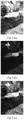
- Figs. 3(a), 3(b), and 3(c) are schematic diagrams of image composition effects using an HDR technology.
- Fig. 3(a) is an image exposed with a relatively long exposure time, which shows a local overexposure, i.e., too high luminance at local patches.
- Fig. 3(b) is an image exposed with a relatively short exposure time, which shows over darkness at local patches, i.e., too low luminance at local patches. It is seen from Figs. 3(a) and 3(b) that overexposure or over darkness at local patches will cause the image unclear with a poor display effect.
- Fig. 3(c) is a final image obtained by image composition using an HDR technology based on the images shown in Fig. 3(a) and Fig. 3(b) .
- the final image obtained by image composition using the HDR technology has a moderate luminance with a fine image display effect.
- the RGBIR sensor 130 may pre-save a first exposure time length and a second exposure time length, wherein the first exposure time length and the second exposure time length may be identical or different. Further, the RGBIR sensor 130 may perform more than twice exposures during each round of exposure process according to the stored first exposure time length and second exposure time length.
- the RGBIR sensor 130 may sense the filtered visible light and the filtered infrared light according to a first exposure time length stored during at least one exposure in each round of exposure process, to generate a first RGBIR image; and sense the filtered visible light and the filtered infrared light according to a second exposure time length stored during another exposure or other multiple exposures in the round of exposure process, to generate a second RGBIR image, so as to generate a fine dehazed image using the HDR/WDR image generating method based on the first RGBIR image and the second RGBIR image.
- the processor 140 is configured to remove, for the first RGBIR image generated by the RGBIR sensor 130, the infrared IR component from the first RGBIR image, to obtain an average luminance of an RGB image corresponding to the first RGBIR image; remove, for each second RGBIR image generated by the RGBIR sensor 130, RGB components from the second RGBIR image, to obtain an average luminance of an IR image corresponding to the second RGBIR image; and adjust the first exposure time length according to the average luminance of the RGB image and a first target luminance value preconfigured; adjust the second exposure time length according to the average luminance of the IR image and a second target luminance value preconfigured; and transmit the adjusted exposure time lengths to the RGBIR sensor 130, and generate the dehazed image based on the first RGBIR image and the second RGBIR image.
- the dehazed image may be generated using the HDR/WDR image generating method based on the first RGBIR image and the second RGBIR image generated by the RGBIR sensor 130.
- quality of the first RGBIR image and second RGBIR image is an important factor that affects the display effect of the final dehazed image.
- the display effect of the dehazed image may be enhanced.
- the first exposure time length and the second exposure time length are important factors affecting the quality of the first RGBIR image and the second RGBIR image.
- the processor 140 in the image acquiring apparatus may adjust the first exposure time length and the second exposure time length so as to cause the RGB components and the IR component in the image to be balanced.
- the adjusted first exposure time length and second exposure time length may be transmitted to the RGBIR sensor 130 such that the RGBIR sensor 130 may generate the first RGBIR image and the second RGBIR image according to the adjusted first exposure time length and second exposure time length, thereby enhancing the quality of the first RGBIR image and the second RGBIR image; further, when the processor 140 generates the dehazed image based on the first RGBIR image and the second RGBIR image, the display effect of the dehazed image may be enhanced.
- the processor 140 may remove, for each first RGBIR image generated by the RGBIR sensor 130, an IR component from the first RGBIR image, to obtain an average luminance of an RGB image corresponding to the first RGBIR image; remove, for each second RGBIR image generated by the RGBIR sensor 130, RGB components from the second RGBIR image, to obtain an average luminance of an IR image corresponding to the second RGBIR image; adjust the first exposure time length according to the average luminance of the RGB image and the preconfigured first target luminance value; and adjust the second exposure time length according to the average luminance of the IR image and the preconfigured second target luminance value.
- the processor 140 may adjust the corresponding first exposure time length and second exposure time length for the first RGBIR image and the second RGBIR image generated by the RGBIR sensor 130, and transmit the adjusted first exposure time length and second exposure time length to the RGBIR sensor 130; after the RGBIR sensor 130 generates a new first RGBIR image and a new second RGBIR image using the adjusted first exposure time length and second exposure time length, the processor 140 may further adjust the current first exposure time length and second exposure time length according to the new first RGBIR image and second RGBIR image. With this cycle going on and on, both the first exposure time length and the second exposure time length may reach a stable value.
- the RGBIR sensor 130 After the RGBIR sensor 130 generates a first RGBIR image and a second RGBIR image according to the stable first and second exposure time lengths, the RGB components and the IR component in the dehazed image generated by the processor based on the first RGBIR image and the second RGBIR image may reach a balance, thereby achieving a fine display effect.
- An embodiment of the present application provides an image acquiring apparatus implementing image dehazing, wherein an optical filter in the image acquiring apparatus filters visible light and infrared light converged by a lens to filter out a near-infrared visible light transition band from the visible light and infrared light; during at least one exposure in each round of exposure process, the RGBIR sensor generates a first RGBIR image based on a first exposure time length and generates a second RGBIR image based on a second exposure time length; the processor adjusts the first exposure time length of the RGBIR sensor according to an average luminance of the RGB image corresponding to the first RGBIR image and a preconfigured first target luminance value, adjusts the second exposure time length of the RGBIR sensor according to the average luminance of the IR image corresponding to the second RGBIR image and a preconfigured second target luminance value, and generates a dehazed image according to the first RGBIR image and the second RGBIR image.
- the RGBIR sensor is adopted in the embodiments of the present application to generate the first RGBIR image and the second RGBIR image
- the generated images are color images containing infrared information, thus the finally generated image has a fine dehazing effect.
- the image acquiring apparatus adjusts the first exposure time length and the second exposure time length based on the first RGBIR image and the second RGBIR image generated during each exposure, thereby causing the RGB components and the IR component in the images to reach a balance, which guarantees the display effect of the finally generated dehazed image.
- the optical filter 120 may be configured for filtering out the near-infrared visible light transition band from the visible light and infrared light.
- the optical filter 120 may contain an optical filter band with a lower wavelength limit T1 and an upper wavelength limit T2.
- the lower limit T1 may fall into a wavelength range from 600 nm to 800 nm
- the upper limit T2 is greater than T1 and may fall into a wavelength range from 750 nm to 1000 nm.
- selection of T2 may follow a principle of filtering part of light having a relatively large spectrum response discrepancy among the R, G, B components and IR component while only retaining the part having a close spectrum response in the four components.
- the processor removes, for the first RGBIR image generated by the RGBIR sensor 130, IR component from the first RGBIR image to obtain an average luminance of the RGB image corresponding to the first RGBIR image, which may guarantee the RGB image having a relatively small spectrum response discrepancy among the R, G, B components.
- Fig. 4 shows a schematic diagram of spectrum response of an optical filter.
- respective curves in the figure show light energy magnitudes of R, G, B, and IR components at respective bands, wherein 410 represents the R component, 420 represents the G component, 430 represents the B component, and 440 represents the IR component; T1 and T2 represent the lower limit and the upper limit of a filter band of the optical filter, the shadow portions at two sides represent through bands, and the middle portion represents a filtered band.
- the bold black line represents an ideal spectrum response curve of the optical filter. It needs to be noted that in practical applications, the actual filter response cannot reach vertical, and there will be a certain slope and fluctuation.
- the processor 140 may be specifically configured to, use an interpolation method to determine an interpolated IR luminance value of an image element in the first RGBIR image, wherein the image element includes each image element of R component, G component, B component in the first RGBIR image corresponding to the image element of the IR component, and subtract the interpolated IR luminance value from the luminance value of the image element, to obtain an adjusted luminance value of the image element; and determine an average luminance of the RGB image corresponding to the first RGBIR image based on the adjusted luminance value of each image element of R component, G component, B component.
- Fig. 5 is a schematic diagram of a process of determining the luminance value of each image element of R component, G component, B component in an RGBIR image using an interpolation method.
- 510 represents a schematic diagram of an RGBIR image outputted by the RGBIR sensor
- 520 represents an IR image element lattice in the RGBIR image
- the IR image element lattice shown in 520 is subjected to interpolation, the result of interpolation is shown in 530.
- 540, 550, and 560 represent an R image element lattice, a G image element lattice, and a B image element lattice corresponding to the RGBIR image shown in 510.
- the interpolated IR luminance value, in the IR image element lattice shown in 530, corresponding to each image element in the R image element lattice shown in 540 is subtracted from the luminance value of the image element, to determine an adjusted luminance value of the image element in the R image element lattice;
- the interpolated IR luminance value, in the IR image element lattice shown in 530, corresponding to each image element in the G image element lattice shown in 550 is subtracted from the luminance value of the image element, to determine an adjusted luminance value of the image element in the G image element lattice;
- the interpolated IR luminance value, in the IR image element lattice shown in 530, corresponding to each image element in the B image element lattice shown in 560 is subtracted from the luminance value of the image element, to determine an adjusted luminance value of the image element in the B image element lattice.
- the processor 140 may also be configured to determine a white balance gain of each RGB image, and generate a dehazed image according to the white balance gain of each RGB image, the first RGBIR image, and the second RGBIR image.
- the processor may partition, for the RGB images corresponding to each first RGBIR image, each RGB image into a plurality of small patches, and calculates an average luminance of each R, G, and B component of each small patch, so as to obtain the white balance gain of each RGB image according to the white balance algorithm; and further generate a dehazed image according to the white balance gain of the RGB image, the first RGBIR image, and the second RGBIR image.
- the processor 140 may determine whether the first difference value between an average luminance of the RGB image and the preconfigured first target luminance value is greater than a first threshold; if so, it may be indicated that the current average luminance of the RGB images is greater than the preconfigured first target luminance value; in this case, the first exposure time length may be shortened, causing the average luminance of the RGB image to be proximate to the preconfigured first target luminance value.
- the first difference is smaller than a second threshold, it may be indicated that the current average luminance of the RGB image is smaller than the preconfigured first target luminance value; in this case, the first exposure time length may be prolonged.
- the first target luminance value is 100, the first threshold is 10, and the second threshold is -10; when the first difference between the average luminance of the RGB image and the preconfigured first target luminance value is greater than the first threshold or smaller than the second threshold, the first exposure time length is adjusted; when the first difference value between the average luminance of the RGB image and the preconfigured first target luminance value is smaller than the first threshold and greater than the second threshold, the first exposure time length may not be adjusted.
- the luminance of the RGB image is required between 90 and 110.
- the first exposure time length is adjusted by comparison with only one target luminance value, the first exposure time length will keep oscillating around the target value. If two thresholds are set, when the average luminance of the RGB image falls within the range between the two thresholds, no adjustment need to be made, which may avoid the issue of oscillation.
- the processor 140 may shorten the first exposure time length with a first step size, e.g., 0.1 ms, 0.2 ms, etc.; and prolong the first exposure time length with a second step size, e.g., 0.1 ms, 0.2 ms, etc.; wherein the first step size and the second step size may be identical or different.
- a first step size e.g., 0.1 ms, 0.2 ms, etc.
- a second step size e.g., 0.1 ms, 0.2 ms, etc.
- the processor 140 may determine whether a second difference value between the average luminance of the IR image and the preconfigured second target luminance value is greater than a third threshold; if so, it may be indicated that the current average luminance of the IR image is greater than the preconfigured second target luminance value; in this case, the second exposure time length may be shortened; when the second difference is smaller than a fourth threshold, it may be indicated that the current average luminance of the IR image is smaller than the preconfigured second target luminance value; in this case, the second exposure time length may be prolonged.
- the second target luminance value is 100, the third threshold is 10, and the fourth threshold is -10; when the second difference between the average luminance of the IR image and the preconfigured second target luminance value is greater than the third threshold or smaller than the fourth threshold, the second exposure time length is adjusted; when the second difference between the average luminance of the IR image and the preconfigured second target luminance value is smaller than the third threshold but greater than the fourth threshold, the second exposure time length may not be adjusted.
- the luminance of the IR image is only required between 90 and 110.
- the second exposure time length is adjusted by comparison with only one target luminance value, the second exposure time length will keep oscillating around the target value. If two thresholds are set, when the average luminance of the RGB image falls within the range between the two thresholds, no adjustment need to be made, which may avoid the issue of oscillation.
- the processor 140 may shorten the second exposure time length with the third step size, e.g., 0.1 ms, 0.2 ms, etc.; and prolong the second exposure time length with the fourth step size, e.g., 0.1 ms, 0.2 ms, and etc.; wherein the third step size and the fourth step size may be identical or different.
- the image acquiring apparatus may be configured as an image dehazing apparatus shown in Fig. 6 .
- the image dehazing apparatus may include: an acquiring module 610, a pre-processing module 620, a processing module 630, a statistical module 640, and a control module 650.
- the acquiring module 610 may include a lens 110, an optical filter 120, and an RGBIR sensor 130 in the image acquiring apparatus shown in Fig. 1 , the lens is configured for converging visible light and infrared light, and the optical filter is configured for filtering the converged visible light and infrared light to filter out a near-infrared visible light transition band from the visible light and infrared light; the RGBIR sensor is configured for sensing the filtered visible light and infrared light according to a first exposure time length stored during at least one exposure in each round of exposure process, to generate a first RGBIR image; and sensing the filtered visible light and the filtered infrared light according to a second exposure time length stored during at least one exposure in the round of exposure process, to thereby generate a second RGBIR image.
- the lens is configured for converging visible light and infrared light
- the optical filter is configured for filtering the converged visible light and infrared light to filter out a near-infrared visible light
- the pre-processing module 620, the processing module 630, the statistical module 640, and the control module 650 may constitute the processor 140 in the image acquiring apparatus shown in Fig. 1 .
- the pre-processing module 620 may obtain, for each first RGBIR image (i.e., image signal 1) acquired by the acquiring module 610, an image signal 2 by removing an IR component from the first RGBIR image; specifically, in an embodiment of the present application, the acquiring module 610 may acquire at least two RGBIR images, e.g., a first RGBIR image and a second RGBIR image, and transmit both of the first RGBIR image and second RGBIR image to the pre-processing module 620; after the pre-processing module transmits respective processed image signals 2 to the processing module 630, the processing module 630 may generate a resultant image (namely, a dehazed image) using the HDR/WDR technology based on the respective image signals 2.
- a resultant image namely, a dehazed image
- the pre-processing module 620 may also transmit the processed image signals 2 to the statistical module 640; the statistical module 640 may be configured to obtain the average luminance of the RGB image corresponding to each first RGBIR imag, and obtain the average luminance of the IR image corresponding to each second RGBIR.
- the statistical module 640 after obtaining the average luminance of each RGB image and the average luminance of the IR image, may transmit the result to the control module 650; the control module 650 may adjust the first exposure time length for the acquiring module 610 to acquire the first RGBIR image based on the average luminance of the RGB image and the preconfigured first target luminance value, adjust the second exposure time length for the acquiring module 610 to acquire the second RGBIR image based on the average luminance of the IR image and the preconfigured second target luminance value, and may transmit the adjusted exposure time lengths to the acquiring module 610, such that the acquiring module 610 may acquire the first RGBIR image and the second RGBIR image based on the adjusted first exposure time length and second exposure time length.
- an embodiment of the present application further provides an image dehazing method.
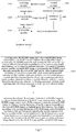
- the method may include: S701: receiving each first RGBIR image and each second RGBIR image transmitted by an RGBIR sensor, wherein the first RGBIR image is generated by the RGBIR sensor through sensing the filtered visible light and the filtered infrared light according to a first exposure time length stored during one exposure or multiple exposures in a round of exposure process; and the second RGBIR image is generated by the RGBIR sensor through sensing the filtered visible light and the filtered infrared light according to a second exposure time length stored during another exposure or other multiple exposures in the round of exposure process; wherein the first exposure time length and the second exposure time length is either identical or different, and the filtered visible light and the filtered infrared light are obtained by filtering out a near-infrared visible light transition band from converged visible light and infrared visible light.
- the method provided by an embodiment of the present application may be applied to an image acquiring apparatus, and may specifically be applied to a processor in the image acquiring apparatus.
- the image acquiring apparatus in the embodiments of the present application may further include an RGBIR sensor.
- the RGBIR sensor is an image sensor and also a CMOS sensor. Different from a traditional image sensor that outputs Bayer pattern data, the RGBIR sensor transforms half of green through image elements into infrared through image elements, thereby sacrificing half of green channel information for an independent near-infrared channel (with a sensible wavelength ranging about 800 ⁇ 1000 nm) information.
- the RGBIR sensor may pre-save a first exposure time length and a second exposure time length, wherein the first exposure time length and the second exposure time length may be identical or different. Further, the RGBIR sensor may perform more than twice exposures during each round of exposure process according to the stored first exposure time length and second exposure time length. Specifically, the RGBIR sensor may sense the filtered visible light and infrared light according to the stored first exposure time length during at least one exposure in each round of exposure process, to thereby generate a first RGBIR image; and sense the filtered visible light and infrared light according to the stored second exposure time length during another exposure in the round of exposure process, to thereby generate a second RGBIR image.
- the filtered visible light and infrared light are obtained by filtering out the near-infrared visible light transition band from the converged visible light and infrared light.
- the near-infrared visible light transition band may be a band ranging from 600 nm to 1000 nm.
- the processor of the image acquiring apparatus may receive the first RGBIR image and the second RGBIR image transmitted by the RGBIR sensor to generate a dehazed image based on the first RGBIR image and second RGBIR image.
- the processor may remove the IR component from the first RGBIR image to obtain the average luminance of the RGB image corresponding to the first RGBIR image; remove the RGB components from the second RGBIR image to obtain the average luminance of the IR image corresponding to the second RGBIR image; and adjust the first exposure time length based on the average luminance of the RGB image and the preconfigured first target luminance value; adjust the second exposure time length based on the average luminance of the IR image and the preconfigured second target luminance value; transmit the adjusted exposure time lengths to the RGBIR sensor; and generate the dehazed image based on the first RGBIR image and the second RGBIR image.
- the processor may generate the dehazed image using the HDR/WDR image generating method based on the first RGBIR image and the second RGBIR image.
- an HDR/WDR image generating method When acquiring an image containing a scene with a relatively large dynamic range, some local parts in the image may be too dark, while some other local parts may be overexposed. Therefore, to obtain an image having a good result, two or more images having a same photography scene but different luminance may be obtained through two or more exposures with different time lengths during one round of exposure process. Because each exposure has a different time length, ideal information content may be obtained based on local features with different luminance in respective images. Then, by combining the information contained in the images, a final image with extended dynamic range and enhanced details may be obtained. This method may be referred to as an HDR/WDR image generating method.
- the processor in the image acquiring device may adjust the first exposure time length and the second exposure time length so as to cause the RGB components and the IR component in the image to be balanced.
- the adjusted first exposure time length and second exposure time length may be transmitted to the RGBIR sensor such that the RGBIR sensor may generate the first RGBIR image and the second RGBIR image according to the adjusted first exposure time length and second exposure time length, thereby enhancing the quality of the first RGBIR image and the second RGBIR image; further, when the processor generates the dehazed image based on the first RGBIR image and the second RGBIR image, the display effect of the dehazed image may be enhanced.
- the processor may remove, for each first RGBIR image generated by the RGBIR sensor, the IR component from the first RGBIR image to obtain an average luminance of an RGB image corresponding to the first RGBIR image; remove, for each second RGBIR image generated by the RGBIR sensor, the RGB components from the second RGBIR image to obtain an average luminance of an IR image corresponding to the second RGBIR image; adjust the first exposure time length according to the average luminance of the RGB image and the preconfigured first target luminance value; and adjust the second exposure time length according to the average luminance of the IR image and the preconfigured second target luminance value.
- the processor may adjust the corresponding first exposure time length and second exposure time length for the first RGBIR image and the second RGBIR image generated by the RGBIR sensor, and transmit the adjusted first exposure time length and second exposure time length to the RGBIR sensor; after the RGBIR sensor generates a new first RGBIR image and a new second RGBIR image using the adjusted first exposure time length and second exposure time length, the processor may further adjust the current first exposure time length and second exposure time length according to the new first RGBIR image and second RGBIR image. With such a cycle going on and on, the first exposure time length and the second exposure time length may reach stable values.
- the RGBIR sensor After the RGBIR sensor generates a first RGBIR image and a second RGBIR image according to the stable first exposure time length and second exposure time length, the RGB components and the IR component in the dehazed image generated by the processor based on the first RGBIR image and the second RGBIR image may reach a balance, thereby achieving a good display effect.
- An embodiment of the present application provides an image dehazing method applied to an image acquiring apparatus, wherein an optical filter in the image acquiring apparatus filters visible light and infrared light converged by a lens to filter out a near-infrared visible light transition band from the visible light and infrared light; during at least one exposure in each round of exposure process, the RGBIR sensor generates a first RGBIR image based on a first exposure time length and generates a second RGBIR image according to a second exposure time length; the processor adjusts the first exposure time length of the RGBIR sensor according to an average luminance of the RGB image corresponding to the first RGBIR image and the preconfigured first target luminance value, adjusts the second exposure time length of the RGBIR sensor according to an average luminance of the IR image corresponding to the second RGBIR image and a preconfigured second target luminance value, and generates a dehazed image according to the first RGBIR image and the second RGBIR image.
- the generated images are color images containing infrared information, such that the finally generated image has a relatively good dehazing effect. Additionally, the image acquiring apparatus adjusts the first exposure time length and the second exposure time length based on the first RGBIR image and the second RGBIR image generated during each exposure, thereby causing the RGB components and the IR component in the image to reach a balance, which guarantees the display effect of the finally generated dehazed image.
- the processor is may subtract the infrared IR component from the first RGBIR image to obtain an average luminance of an RGB image corresponding to the first RGBIR image; determine an interpolated IR luminance value of an image element in the first RGBIR image using an interpolation method, wherein the image element includes each image element of R component, G component, B component in the first RGBIR image corresponding to the image element of the IR component; then subtract an interpolated IR luminance value corresponding to each image element of R component, G component, B component from the luminance value of the image element, to determine an adjusted luminance value of the image element; and determine an average luminance of the RGB image corresponding to the first RGBIR image based on the adjusted luminance value of each image element of R component, G component, B component.
- the average luminance of the RGB image corresponding to the first RGBIR image may be determined based on the adjusted luminance value of each image element of R component, G component, B component and a preconfigured weight value corresponding to each image element.
- the processor when generating a dehazed image based on each first RGBIR image and each second RGBIR image, the processor may firstly determine the white balance gain of each RGB image, and then generate the dehazed image based on the white balance gain of each RGB image, the first RGBIR image, and the second RGBIR image.
- the processor may partition, for each first RGBIR image, each RGB image into a plurality of small patches, and calculates an average luminance of each R, G, and B component of each small patch, so as to obtain the white balance gain of the the RGB image according to the white balance algorithm; and further generate a dehazed image based on the white balance gain of each RGB image, the first RGBIR image, and the second RGBIR image.
- prior arts may be adopted during the process of obtaining the white balance gain of each RGB image based on the white balance algorithm and the process of generating a dehazed image based on the white balance gain of the RGB image, the first RGBIR image, and the second RGBIR image; therefore, the two processes will not be detailed in the embodiments of the present application.
- the processor when adjusting the first exposure time length based on the average luminance of the RGB image and the preconfigured first target luminance value, may specifically determine whether a first difference value between the average luminance of the RGB image and a preconfigured first target luminance value is greater than a first threshold; if so, shorten the first exposure time length; when the first difference value is smaller than a second threshold, prolong the first exposure time length.
- the processor determines that the first difference value between the average luminance of the RGB image and the preconfigured first target luminance value is greater than the first threshold, it may be indicated that the current average luminance of the RGB image is greater than the preconfigured first target luminance value; in this case, the first exposure time length may be shortened, causing the average luminance of the RGB image to be proximate to the preconfigured first target luminance value.
- the first difference value is smaller than the second threshold, it may be indicated that the current average luminance of the RGB image is smaller than the preconfigured first target luminance value; in this case, the first exposure time length may be prolonged.
- the processor may shorten the first exposure time length with the first step size, e.g., 0.1 ms, 0.2 ms, etc.; and prolong the first exposure time length with the second step size, e.g., 0.1 ms, 0.2 ms, etc., wherein the first step size and the second step size may be identical or different.
- the processor may specifically determine whether a second difference value between the average luminance of the IR image and the preconfigured second target luminance is greater than a third threshold; if so, shorten the second exposure time length; when the second difference is smaller than a fourth threshold, prolong the second exposure time length.
- the processor determines that the second difference value between the average luminance of the IR image and the preconfigured second target luminance value is greater than the third threshold, it may be indicated that the current average luminance of the IR image is greater than the preconfigured second target luminance value; in this case, the second exposure time length may be shortened.
- the second difference is smaller than the fourth threshold, it may be indicated that the current average luminance of the IR image is smaller than the preconfigured second target luminance value; in this case, the second exposure time length may be prolonged.
- the processor may shorten the second exposure time length with a third step size, e.g., 0.1 ms, 0.2 ms, etc., and prolong the second exposure time length with a fourth step size, e.g., 0.1 ms, 0.2 ms, etc., wherein the third step size and the fourth step size may be identical or different.
- a third step size e.g., 0.1 ms, 0.2 ms, etc.
- a fourth step size e.g., 0.1 ms, 0.2 ms, etc.
- Embodiments of the present application provide an image dehazing method and an image acquiring apparatus implementing image dehazing, wherein the optical filter in the image acquiring apparatus filters visible light and infrared light converged by a lens to filter out a near-infrared visible light transition band from the visible light and infrared light; the RGBIR sensor, during at least one exposure in each round of exposure process, generates a first RGBIR image according to a first exposure time length, and generates a second RGBIR image according to a second exposure time length; the processor adjusts the first exposure time length of the RGBIR sensor based on the average luminance of the RGB image corresponding to the first RGBIR image and the preconfigured first target luminance value, adjusts the second exposure time length of the RGBIR sensor based on the average luminance of the IR image corresponding to the second RGBIR image and the preconfigured second target luminance value, and generates a dehazed image according to the first RGBIR image and the second RGBIR image.
- the embodiments of the present application adopt an RGBIR sensor to generate the first RGBIR image and the second RGBIR image, thus the generated images are color images and contain infrared information, such that the finally generated image has a good dehazing effect; additionally, the image acquiring apparatus adjusts the first exposure time length and the second exposure time length based on the first RGBIR image and the second RGBIR image generated during each exposure, causing the RGB components and the IR component in the images to be balanced, which guarantees the display effect of the finally generated dehazed image.
- the present application further provides a storage medium, wherein the storage medium is configured for storing executable codes, the executable codes can implement an image dehazing method according to the present application when being executed, wherein the image dehazing method of the present application includes:
- the embodiments of the present application adopt an RGBIR sensor to generate the first RGBIR image and the second RGBIR image, the generated images are color images and contain infrared information, such that the finally generated image has a good dehazing effect; additionally, the image acquiring device adjusts the first exposure time length and the second exposure time length based on the first RGBIR image and the second RGBIR image generated during each exposure, causing the RGB components and the IR component in the image to be balanced, which guarantees the display effect of the finally generated dehazed image.
- the present application further provides an application which, implements an image dehazing method of the present application when being executed, wherein the image dehazing method of the present application includes:
- the embodiments of the present application adopt an RGBIR sensor to generate the first RGBIR image and the second RGBIR image, the generated images are color images and contain infrared information, such that the finally generated image has a good dehazing effect; additionally, the image acquiring device adjusts the first exposure time length and the second exposure time length based on the first RGBIR image and the second RGBIR image generated during each exposure, causing the RGB components and the IR component in the image to be balanced, which guarantees the display effect of the finally generated dehazed image.
Landscapes
- Engineering & Computer Science (AREA)
- Multimedia (AREA)
- Signal Processing (AREA)
- Physics & Mathematics (AREA)
- General Physics & Mathematics (AREA)
- Theoretical Computer Science (AREA)
- Health & Medical Sciences (AREA)
- Toxicology (AREA)
- Optics & Photonics (AREA)
- Color Television Image Signal Generators (AREA)
- Studio Devices (AREA)
- Image Processing (AREA)
Claims (9)
- Appareil d'acquisition d'image mettant en œuvre un débrumage d'image, comprenant :une lentille (110), configurée pour faire converger de la lumière visible et de la lumière infrarouge ;un filtre optique (120), configuré pour filtrer la lumière visible et la lumière infrarouge convergées pour éliminer par filtrage une bande de transition de l'infrarouge proche à la lumière visible de la lumière visible et de la lumière infrarouge ;un capteur RVBIR (130), configuré pour détecter, pendant une ou plusieurs expositions dans une ronde de processus d'exposition, la lumière visible filtrée et la lumière infrarouge filtrée selon une première longueur de temps d'exposition, pour générer une première image RVBIR ; et détecter, pendant une ou plusieurs autres expositions dans la ronde de processus d'exposition, la lumière visible filtrée et la lumière infrarouge filtrée selon une deuxième longueur de temps d'exposition, pour générer une deuxième RVGIR ; sachant que la première longueur de temps d'exposition et la deuxième longueur de temps d'exposition sont soit identiques soit différentes ;un processeur (140), configuré pour enlever la composante infrarouge IR de la première image RVGIR, pour obtenir une luminance moyenne d'une image RVB correspondant à la première image RVBIR ; enlever les composantes RVB de la deuxième image RVBIR pour obtenir une luminance moyenne d'une image IR correspondant à la deuxième image RVBIR ; et régler la première longueur de temps d'exposition selon la luminance moyenne de l'image RVB et une première valeur de luminance cible préconfigurée ; et régler la deuxième longueur de temps d'exposition selon la luminance moyenne de l'image IR et une deuxième valeur de luminance cible préconfigurée ; et transmettre les longueurs de temps d'exposition réglées au capteur RVBIR (130),sachant que le réglage de la première longueur de temps d'exposition selon la luminance moyenne de l'image RVB et une première valeur de luminance cible préconfigurée comprend :
le raccourcissement de la première longueur de temps d'exposition avec une première taille de pas si la première valeur de différence entre la luminance moyenne de l'image RVB et la première valeur de luminance cible est supérieure à un premier seuil ; ou le prolongement de la première longueur de temps d'exposition avec une deuxième taille de pas lorsque la première valeur de différence est inférieure à un deuxième seuil, sachant que le premier seuil est supérieur au deuxième seuil, et la première taille de pas et la deuxième taille de pas sont soit identiques soit différentes,sachant que le réglage de la deuxième longueur de temps d'exposition selon la luminance moyenne de l'image IR et une deuxième valeur de luminance cible préconfigurée comprend :
le raccourcissement de la deuxième longueur de temps d'exposition avec une troisième taille de pas si la deuxième valeur de différence entre la luminance moyenne de l'image IR et la deuxième valeur de luminance cible est supérieure à un troisième seuil ; ou le prolongement de la deuxième longueur de temps d'exposition avec une quatrième taille de pas lorsque la deuxième valeur de différence est inférieure à un quatrième seuil, sachant que le troisième seuil est supérieur au quatrième seuil, et la troisième taille de pas et la quatrième taille de pas sont soit identiques soit différentes,sachant que, lors de la réception des première et deuxième longueurs de temps d'exposition réglées, le capteur RVBIR (130) détecte, pendant une ou plusieurs expositions dans une ronde de processus d'exposition, la lumière visible filtrée et la lumière infrarouge filtrée selon la première longueur de temps d'exposition réglée pour générer une nouvelle première image RVBIR ; et détecte, pendant une ou plusieurs autres expositions dans la ronde de processus d'exposition, la lumière visible filtrée et la lumière infrarouge filtrée selon la deuxième longueur de temps d'exposition réglée pour générer une nouvelle deuxième image RVBIR,sachant que, lorsque à la fois la première longueur de temps d'exposition réglée et la deuxième longueur de temps d'exposition réglée atteignent une valeur stable, le processeur (140) génère une image débrumée, sur la base d'une première image RVBIR générée selon cette première longueur de temps d'exposition et d'une deuxième image RVGIR générée selon cette deuxième longueur de temps d'exposition. - L'appareil d'acquisition d'image selon la revendication 1, sachant que la bande de transition de l'infrarouge proche à la lumière visible se rapporte à une bande allant de 600 nm à 1000 nm ;
ou
sachant que le processeur (140) est configuré pour utiliser un procédé d'interpolation pour déterminer une valeur de luminance IR interpolée d'un élément d'image dans la première image RVGIR, sachant que l'élément d'image inclut chaque élément d'image de composante R, de composante V, de composante B dans la première image RVBIR correspondant à l'élément d'image de la composante IR, sachant que le procédé d'interpolation inclut une interpolation proximale ou une interpolation linéaire ; et soustraire la valeur de luminance IR interpolée de la valeur de luminance de l'élément d'image, pour obtenir une valeur de luminance réglée de l'élément d'image ; et déterminer une luminance moyenne de l'image RVB correspondant à la première image RVBIR sur la base de la valeur de luminance réglée de chaque élément d'image de composante R, de composante V, de composante B. - L'appareil d'acquisition d'image selon la revendication 1, sachant que le processeur (140) est configuré pour partitionner l'image RVB correspondant à la première image RVBIR dans une pluralité de petites pastilles, et calculer une luminance moyenne de chaque composante R, V, et B de chaque petite pastille, de manière à obtenir un gain d'équilibre de blanc de l'image RVB selon l'algorithme d'équilibre de blanc, et générer l'image débrumée sur la base du gain d'équilibre de blanc de l'image RVB, de la première image RVBIR et de la deuxième image RVBIR.
- Procédé de débrumage d'image, appliqué à un appareil d'acquisition d'image, le procédé comprenant :la réception (S701) de chaque première image RVBIR et de chaque deuxième image RVBIR transmises par un capteur RVBIR (130), sachant que la première image RVBIR est générée par le capteur RVBIR (130) par détection, pendant une exposition ou de multiples expositions dans une ronde de processus d'exposition, de la lumière visible filtrée et de la lumière infrarouge filtrée selon une première longueur de temps d'exposition ; et la deuxième image RVBIR est générée par le capteur RVBIR (130) par détection, pendant une exposition ou de multiples expositions dans la ronde de processus d'exposition, de la lumière visible filtrée et de la lumière infrarouge filtrée selon une deuxième longueur de temps d'exposition ; sachant que la première longueur de temps d'exposition et la deuxième longueur de temps d'exposition sont soit identiques soit différentes, et la lumière visible filtrée et la lumière infrarouge filtrée sont obtenues en éliminant par filtrage une bande de transition de l'infrarouge proche à la lumière visible de la lumière visible et de la lumière visible infrarouge convergées ; etl'enlèvement (S702) de la composante infrarouge IR de la première image RVBIR pour obtenir une luminance moyenne d'une image RVB correspondant à la première image RVBIR ; l'enlèvement des composantes RVB de la deuxième image RVBIR pour obtenir une luminance moyenne d'une image IR correspondant à la deuxième image RVBIR ; et le réglage de la première longueur de temps d'exposition selon la luminance moyenne de l'image RVG et une première valeur de luminance cible préconfigurée ; le réglage de la deuxième longueur de temps d'exposition selon la luminance moyenne de l'image IR et une deuxième valeur de luminance cible préconfigurée ; et la transmission des longueurs de temps d'exposition réglées au capteur RVBIR (130),sachant que le réglage de la première longueur de temps d'exposition selon la luminance moyenne de l'image RVB et une première valeur de luminance cible préconfigurée comprend :
le raccourcissement de la première longueur de temps d'exposition avec une première taille de pas si la première valeur de différence entre la luminance moyenne de l'image RVB et la première valeur de luminance cible est supérieure à un premier seuil ; ou le prolongement de la première longueur de temps d'exposition avec une deuxième taille de pas lorsque la première valeur de différence est inférieure à un deuxième seuil, sachant que le premier seuil est supérieur au deuxième seuil, et la première taille de pas et la deuxième taille de pas sont soit identiques soit différentes ;sachant que le réglage de la deuxième longueur de temps d'exposition selon la luminance moyenne de l'image IR et une deuxième valeur de luminance cible préconfigurée comprend :
le raccourcissement de la deuxième longueur de temps d'exposition avec une troisième taille de pas si la deuxième valeur de différence entre la luminance moyenne de l'image IR et la deuxième valeur de luminance cible est supérieure à un troisième seuil ; ou le prolongement de la deuxième longueur de temps d'exposition avec une quatrième taille de pas lorsque la deuxième valeur de différence est inférieure à un quatrième seuil, sachant que le troisième seuil est supérieur au quatrième seuil, et la troisième taille de pas et la quatrième taille de pas sont soit identiques soit différentes,sachant que, lors de la réception des première et deuxième longueurs de temps d'exposition réglées, le capteur RVBIR (130) détecte, pendant une ou plusieurs expositions dans une ronde de processus d'exposition, la lumière visible filtrée et la lumière infrarouge filtrée selon la première longueur de temps d'exposition réglée pour générer une nouvelle première image RVBIR ; et détecte, pendant une ou plusieurs autres expositions dans la ronde de processus d'exposition, la lumière visible filtrée et la lumière infrarouge filtrée selon la deuxième longueur de temps d'exposition réglée pour générer une nouvelle deuxième image RVBIR,sachant que, lorsque à la fois la première longueur de temps d'exposition réglée et la deuxième longueur de temps d'exposition réglée atteignent une valeur stable, le processeur (140) génère une image débrumée, sur la base d'une première image RVBIR générée selon cette première longueur de temps d'exposition et d'une deuxième image RVGIR générée selon cette deuxième longueur de temps d'exposition. - Le procédé selon la revendication 4, sachant que la bande de transition de l'infrarouge proche à la lumière visible se rapporte à une bande allant de 600 nm à 1000 nm ;
ou
sachant que l'enlèvement de la composante infrarouge IR de la première image RVBIR pour obtenir une luminance moyenne d'une image RVB correspondant à la première image RVBIR comprend :la détermination d'une valeur de luminance IR interpolée d'un élément d'image dans la première image RVGIR moyennant un procédé d'interpolation, sachant que l'élément d'image inclut chaque élément d'image de composante R, de composante V, de composante B dans la première image RVBIR correspondant à l'élément d'image de la composante IR, sachant que le procédé d'interpolation inclut une interpolation proximale ou une interpolation linéaire ;la soustraction de la valeur de luminance IR interpolée de la valeur de luminance de l'élément d'image, pour obtenir une valeur de luminance réglée de l'élément d'image ; etla détermination d'une luminance moyenne de l'image RVB correspondant à la première image RVBIR sur la base de la valeur de luminance réglée de chaque élément d'image de composante R, de composante V, de composante B. - Le procédé selon la revendication 5, sachant que la détermination d'une luminance moyenne de l'image RVB correspondant à la première image RVBIR sur la base de la valeur de luminance réglée de chaque élément d'image de composante R, de composante V, de composante R, comprend :
la détermination d'une luminance moyenne de l'image RVG correspondant à la première image RVBIR sur la base de la valeur de luminance réglée de chaque élément d'image de composante R, de composante V, de composante B et d'une valeur de poids préconfigurée correspondant à l'élément d'image. - Le procédé selon la revendication 6, sachant que la génération d'une image débrumée sur la base de la première image RVBIR et de la deuxième image RVBIR comprend :le partitionnement de l'image RVB correspondant à la première image RVBIR en une pluralité de petites pastilles, et le calcul d'une luminance moyenne de chaque composante R, V, et B de chaque petite pastille, de manière à obtenir un gain d'équilibre de blanc de l'image RVB selon l'algorithme d'équilibre de blanc, etla génération de l'image débrumée sur la base du gain d'équilibre de blanc de l'image RVB, de la première image RVBIR et de la deuxième image RVBIR.
- Support de stockage, sachant que le support de stockage est configuré pour stocker des codes exécutables, les codes exécutables sont configurés pour mettre en œuvre le procédé de débrumage d'image selon l'une quelconque des revendications 4 à 7 lorsqu'ils sont exécutés.
- Programme d'ordinateur comprenant des instructions qui, lorsque le programme est exécuté par un ordinateur, font effectuer à l'ordinateur le procédé de débrumage d'image selon l'une quelconque des revendications 4 à 7.
Applications Claiming Priority (2)
| Application Number | Priority Date | Filing Date | Title |
|---|---|---|---|
| CN201610355946.9A CN107438170B (zh) | 2016-05-25 | 2016-05-25 | 一种图像透雾方法及实现图像透雾的图像采集设备 |
| PCT/CN2017/073347 WO2017202061A1 (fr) | 2016-05-25 | 2017-02-13 | Procédé de désembuage d'image et appareil de capture d'image mettant en œuvre un désembuage d'image |
Publications (3)
| Publication Number | Publication Date |
|---|---|
| EP3468178A1 EP3468178A1 (fr) | 2019-04-10 |
| EP3468178A4 EP3468178A4 (fr) | 2019-05-29 |
| EP3468178B1 true EP3468178B1 (fr) | 2020-08-05 |
Family
ID=60411064
Family Applications (1)
| Application Number | Title | Priority Date | Filing Date |
|---|---|---|---|
| EP17801917.0A Active EP3468178B1 (fr) | 2016-05-25 | 2017-02-13 | Procédé de désembuage d'image et appareil de capture d'image mettant en oeuvre un désembuage d'image |
Country Status (4)
| Country | Link |
|---|---|
| US (1) | US11057592B2 (fr) |
| EP (1) | EP3468178B1 (fr) |
| CN (1) | CN107438170B (fr) |
| WO (1) | WO2017202061A1 (fr) |
Families Citing this family (20)
| Publication number | Priority date | Publication date | Assignee | Title |
|---|---|---|---|---|
| CN107438170B (zh) * | 2016-05-25 | 2020-01-17 | 杭州海康威视数字技术股份有限公司 | 一种图像透雾方法及实现图像透雾的图像采集设备 |
| CN108419061B (zh) * | 2017-02-10 | 2020-10-02 | 杭州海康威视数字技术股份有限公司 | 基于多光谱的图像融合设备、方法及图像传感器 |
| CN112788249B (zh) * | 2017-12-20 | 2022-12-06 | 杭州海康威视数字技术股份有限公司 | 图像融合方法、装置、电子设备及计算机可读存储介质 |
| CN109963066A (zh) * | 2017-12-25 | 2019-07-02 | 深圳市祈飞科技有限公司 | 一种图像获取解析方法以及系统 |
| CN108965654B (zh) | 2018-02-11 | 2020-12-25 | 浙江宇视科技有限公司 | 基于单传感器的双光谱摄像机系统和图像处理方法 |
| WO2020051898A1 (fr) * | 2018-09-14 | 2020-03-19 | 浙江宇视科技有限公司 | Appareil et procédé d'exposition automatique destinés à une image de lumière double, et caméra d'image de lumière double et support d'informations de machine |
| CN110493531B (zh) * | 2018-12-12 | 2021-12-03 | 杭州海康威视数字技术股份有限公司 | 一种图像处理方法和系统 |
| CN110493493B (zh) * | 2019-05-31 | 2022-04-29 | 杭州海康威视数字技术股份有限公司 | 全景细节摄像机及获取图像信号的方法 |
| CN112419163B (zh) * | 2019-08-21 | 2023-06-30 | 中国人民解放军火箭军工程大学 | 一种基于先验知识和深度学习的单张图像弱监督去雾方法 |
| CN113163124B (zh) * | 2020-01-22 | 2022-06-03 | 杭州海康威视数字技术股份有限公司 | 一种成像系统及图像处理方法 |
| EP4131916A4 (fr) * | 2020-04-29 | 2023-05-17 | Huawei Technologies Co., Ltd. | Caméra et procédé d'acquisition d'image |
| US11836888B2 (en) * | 2020-12-21 | 2023-12-05 | Texas Instruments Incorporated | Method and apparatus for processing RGB-infrared (RGB-IR) sensor |
| US11528435B2 (en) * | 2020-12-25 | 2022-12-13 | Industrial Technology Research Institute | Image dehazing method and image dehazing apparatus using the same |
| CN114693542B (zh) * | 2020-12-25 | 2025-10-24 | 财团法人工业技术研究院 | 图像去雾方法和使用图像去雾方法的图像去雾设备 |
| CN113298732A (zh) * | 2021-06-08 | 2021-08-24 | 北京联合大学 | 一种基于区域相似性的图像去雾方法及系统 |
| CN113487516B (zh) * | 2021-07-26 | 2022-09-06 | 河南师范大学 | 一种图像数据的去雾处理方法 |
| CN114037863B (zh) * | 2021-10-29 | 2025-03-25 | 浙江大华技术股份有限公司 | 一种光学滤片类型的判断方法、装置、设备和介质 |
| CN114663311A (zh) * | 2022-03-24 | 2022-06-24 | Oppo广东移动通信有限公司 | 图像处理方法、图像处理装置、电子设备及存储介质 |
| DE102022002637B3 (de) * | 2022-07-19 | 2023-07-27 | Mercedes-Benz Group AG | Kamerasystem und Verfahren zu dessen Betrieb |
| CN116002322B (zh) * | 2022-12-26 | 2026-02-17 | 上海旭宇信息科技有限公司 | 一种实体跟踪定位方法 |
Family Cites Families (21)
| Publication number | Priority date | Publication date | Assignee | Title |
|---|---|---|---|---|
| JPS60130274A (ja) * | 1983-12-19 | 1985-07-11 | Toshiba Corp | 固体撮像装置 |
| US5807666A (en) * | 1995-11-30 | 1998-09-15 | Eastman Kodak Company | Photographic elements with j-aggregating carbocyanine infrared sensitizing dyes |
| JPH10230805A (ja) * | 1997-02-19 | 1998-09-02 | Hitachi Ltd | 自動車用運転支援装置 |
| JP4309728B2 (ja) * | 2003-09-17 | 2009-08-05 | パナソニック株式会社 | 監視用ビデオカメラ |
| US20050140942A1 (en) * | 2003-12-31 | 2005-06-30 | Steven Squires | Image device jamming apparatus and method |
| US10425595B2 (en) * | 2007-11-28 | 2019-09-24 | Flir Systems, Inc. | Modular camera systems and methods |
| JP5293950B2 (ja) * | 2008-03-04 | 2013-09-18 | 株式会社リコー | 個人認証装置及び電子機器 |
| US8749635B2 (en) * | 2009-06-03 | 2014-06-10 | Flir Systems, Inc. | Infrared camera systems and methods for dual sensor applications |
| US9692991B2 (en) * | 2011-11-04 | 2017-06-27 | Qualcomm Incorporated | Multispectral imaging system |
| US9143704B2 (en) | 2012-01-20 | 2015-09-22 | Htc Corporation | Image capturing device and method thereof |
| KR101695252B1 (ko) * | 2012-06-07 | 2017-01-13 | 한화테크윈 주식회사 | 멀티 대역 필터 어레이 기반 카메라 시스템 및 그의 영상 처리 방법 |
| GB201216818D0 (en) * | 2012-09-20 | 2012-11-07 | Bae Systems Plc | Detection of a target in a scene |
| KR101926489B1 (ko) * | 2013-02-04 | 2018-12-07 | 한화테크윈 주식회사 | 다중대역 필터배열 센서를 이용한 영상융합장치 및 방법 |
| CN103118229A (zh) * | 2013-02-06 | 2013-05-22 | 重庆金山科技(集团)有限公司 | 一种成像方法及系统 |
| JP2014216734A (ja) * | 2013-04-24 | 2014-11-17 | 日立マクセル株式会社 | 撮像装置及び撮像システム |
| KR102130756B1 (ko) * | 2013-12-24 | 2020-07-06 | 한화테크윈 주식회사 | 자동 초점 조절 방법 및 자동 초점 조절 장치 |
| JP6677172B2 (ja) * | 2015-01-16 | 2020-04-08 | 日本電気株式会社 | 画像処理装置、画像処理方法およびプログラム |
| CN104683767B (zh) * | 2015-02-10 | 2018-03-06 | 浙江宇视科技有限公司 | 透雾图像生成方法及装置 |
| CN107438170B (zh) * | 2016-05-25 | 2020-01-17 | 杭州海康威视数字技术股份有限公司 | 一种图像透雾方法及实现图像透雾的图像采集设备 |
| US10523856B2 (en) * | 2016-09-08 | 2019-12-31 | Samsung Electronics Co., Ltd. | Method and electronic device for producing composite image |
| CN106780392B (zh) * | 2016-12-27 | 2020-10-02 | 浙江大华技术股份有限公司 | 一种图像融合方法及装置 |
-
2016
- 2016-05-25 CN CN201610355946.9A patent/CN107438170B/zh active Active
-
2017
- 2017-02-13 US US16/303,757 patent/US11057592B2/en active Active
- 2017-02-13 WO PCT/CN2017/073347 patent/WO2017202061A1/fr not_active Ceased
- 2017-02-13 EP EP17801917.0A patent/EP3468178B1/fr active Active
Non-Patent Citations (1)
| Title |
|---|
| None * |
Also Published As
| Publication number | Publication date |
|---|---|
| EP3468178A1 (fr) | 2019-04-10 |
| WO2017202061A1 (fr) | 2017-11-30 |
| US20200322580A1 (en) | 2020-10-08 |
| EP3468178A4 (fr) | 2019-05-29 |
| CN107438170A (zh) | 2017-12-05 |
| CN107438170B (zh) | 2020-01-17 |
| US11057592B2 (en) | 2021-07-06 |
Similar Documents
| Publication | Publication Date | Title |
|---|---|---|
| EP3468178B1 (fr) | Procédé de désembuage d'image et appareil de capture d'image mettant en oeuvre un désembuage d'image | |
| EP3582494B1 (fr) | Appareil et procédé de fusion d'image multispectrale, et capteur d'image | |
| US7460160B2 (en) | Multispectral digital camera employing both visible light and non-visible light sensing on a single image sensor | |
| EP2471258B1 (fr) | Réduction du bruit dans une image en couleurs | |
| CN109951646B (zh) | 图像融合方法、装置、电子设备及计算机可读存储介质 | |
| US8179445B2 (en) | Providing improved high resolution image | |
| US20180035057A1 (en) | Systems and Methods for Photometric Normalization in Array Cameras | |
| US9787915B2 (en) | Method and apparatus for multi-spectral imaging | |
| CN110493536B (zh) | 图像采集装置和图像采集的方法 | |
| US20110157402A1 (en) | Method for processing image, image processing apparatus, and imaging apparatus | |
| CN106488201A (zh) | 一种图像信号的处理方法和系统 | |
| CN107770521B (zh) | 相机拍摄模式调整方法 | |
| CN103905731B (zh) | 一种宽动态图像采集方法及系统 | |
| CN110519489A (zh) | 图像采集方法及装置 | |
| JP2012054904A (ja) | 撮像装置 | |
| CN112217962B (zh) | 摄像机及图像生成方法 | |
| CN110493532A (zh) | 一种图像处理方法和系统 | |
| US20180040108A1 (en) | Image processing device, imaging device, image processing method, and image processing program | |
| CN110493535B (zh) | 图像采集装置和图像采集的方法 | |
| JP5708036B2 (ja) | 撮像装置 | |
| CN115802183B (zh) | 图像处理方法及其相关设备 | |
| CN110493495B (zh) | 图像采集装置和图像采集的方法 | |
| KR20110047540A (ko) | 디지털 카메라 및 그 제어방법 | |
| JP6640555B2 (ja) | カメラシステム | |
| CN118483856A (zh) | 色彩滤镜阵列、图像获取方法、图像传感器及采集装置 |
Legal Events
| Date | Code | Title | Description |
|---|---|---|---|
| STAA | Information on the status of an ep patent application or granted ep patent |
Free format text: STATUS: THE INTERNATIONAL PUBLICATION HAS BEEN MADE |
|
| PUAI | Public reference made under article 153(3) epc to a published international application that has entered the european phase |
Free format text: ORIGINAL CODE: 0009012 |
|
| STAA | Information on the status of an ep patent application or granted ep patent |
Free format text: STATUS: REQUEST FOR EXAMINATION WAS MADE |
|
| 17P | Request for examination filed |
Effective date: 20181207 |
|
| AK | Designated contracting states |
Kind code of ref document: A1 Designated state(s): AL AT BE BG CH CY CZ DE DK EE ES FI FR GB GR HR HU IE IS IT LI LT LU LV MC MK MT NL NO PL PT RO RS SE SI SK SM TR |
|
| AX | Request for extension of the european patent |
Extension state: BA ME |
|
| A4 | Supplementary search report drawn up and despatched |
Effective date: 20190429 |
|
| RIC1 | Information provided on ipc code assigned before grant |
Ipc: H04N 5/33 20060101ALI20190423BHEP Ipc: H04N 7/18 20060101AFI20190423BHEP |
|
| DAV | Request for validation of the european patent (deleted) | ||
| DAX | Request for extension of the european patent (deleted) | ||
| GRAP | Despatch of communication of intention to grant a patent |
Free format text: ORIGINAL CODE: EPIDOSNIGR1 |
|
| STAA | Information on the status of an ep patent application or granted ep patent |
Free format text: STATUS: GRANT OF PATENT IS INTENDED |
|
| INTG | Intention to grant announced |
Effective date: 20200224 |
|
| GRAS | Grant fee paid |
Free format text: ORIGINAL CODE: EPIDOSNIGR3 |
|
| GRAA | (expected) grant |
Free format text: ORIGINAL CODE: 0009210 |
|
| STAA | Information on the status of an ep patent application or granted ep patent |
Free format text: STATUS: THE PATENT HAS BEEN GRANTED |
|
| AK | Designated contracting states |
Kind code of ref document: B1 Designated state(s): AL AT BE BG CH CY CZ DE DK EE ES FI FR GB GR HR HU IE IS IT LI LT LU LV MC MK MT NL NO PL PT RO RS SE SI SK SM TR |
|
| REG | Reference to a national code |
Ref country code: GB Ref legal event code: FG4D |
|
| REG | Reference to a national code |
Ref country code: CH Ref legal event code: EP |
|
| REG | Reference to a national code |
Ref country code: AT Ref legal event code: REF Ref document number: 1300385 Country of ref document: AT Kind code of ref document: T Effective date: 20200815 |
|
| REG | Reference to a national code |
Ref country code: DE Ref legal event code: R096 Ref document number: 602017021287 Country of ref document: DE |
|
| REG | Reference to a national code |
Ref country code: IE Ref legal event code: FG4D |
|
| REG | Reference to a national code |
Ref country code: NL Ref legal event code: FP |
|
| REG | Reference to a national code |
Ref country code: LT Ref legal event code: MG4D |
|
| REG | Reference to a national code |
Ref country code: AT Ref legal event code: MK05 Ref document number: 1300385 Country of ref document: AT Kind code of ref document: T Effective date: 20200805 |
|
| PG25 | Lapsed in a contracting state [announced via postgrant information from national office to epo] |
Ref country code: PT Free format text: LAPSE BECAUSE OF FAILURE TO SUBMIT A TRANSLATION OF THE DESCRIPTION OR TO PAY THE FEE WITHIN THE PRESCRIBED TIME-LIMIT Effective date: 20201207 Ref country code: HR Free format text: LAPSE BECAUSE OF FAILURE TO SUBMIT A TRANSLATION OF THE DESCRIPTION OR TO PAY THE FEE WITHIN THE PRESCRIBED TIME-LIMIT Effective date: 20200805 Ref country code: LT Free format text: LAPSE BECAUSE OF FAILURE TO SUBMIT A TRANSLATION OF THE DESCRIPTION OR TO PAY THE FEE WITHIN THE PRESCRIBED TIME-LIMIT Effective date: 20200805 Ref country code: BG Free format text: LAPSE BECAUSE OF FAILURE TO SUBMIT A TRANSLATION OF THE DESCRIPTION OR TO PAY THE FEE WITHIN THE PRESCRIBED TIME-LIMIT Effective date: 20201105 Ref country code: ES Free format text: LAPSE BECAUSE OF FAILURE TO SUBMIT A TRANSLATION OF THE DESCRIPTION OR TO PAY THE FEE WITHIN THE PRESCRIBED TIME-LIMIT Effective date: 20200805 Ref country code: GR Free format text: LAPSE BECAUSE OF FAILURE TO SUBMIT A TRANSLATION OF THE DESCRIPTION OR TO PAY THE FEE WITHIN THE PRESCRIBED TIME-LIMIT Effective date: 20201106 Ref country code: SE Free format text: LAPSE BECAUSE OF FAILURE TO SUBMIT A TRANSLATION OF THE DESCRIPTION OR TO PAY THE FEE WITHIN THE PRESCRIBED TIME-LIMIT Effective date: 20200805 Ref country code: NO Free format text: LAPSE BECAUSE OF FAILURE TO SUBMIT A TRANSLATION OF THE DESCRIPTION OR TO PAY THE FEE WITHIN THE PRESCRIBED TIME-LIMIT Effective date: 20201105 Ref country code: AT Free format text: LAPSE BECAUSE OF FAILURE TO SUBMIT A TRANSLATION OF THE DESCRIPTION OR TO PAY THE FEE WITHIN THE PRESCRIBED TIME-LIMIT Effective date: 20200805 Ref country code: FI Free format text: LAPSE BECAUSE OF FAILURE TO SUBMIT A TRANSLATION OF THE DESCRIPTION OR TO PAY THE FEE WITHIN THE PRESCRIBED TIME-LIMIT Effective date: 20200805 |
|
| PG25 | Lapsed in a contracting state [announced via postgrant information from national office to epo] |
Ref country code: IS Free format text: LAPSE BECAUSE OF FAILURE TO SUBMIT A TRANSLATION OF THE DESCRIPTION OR TO PAY THE FEE WITHIN THE PRESCRIBED TIME-LIMIT Effective date: 20201205 Ref country code: RS Free format text: LAPSE BECAUSE OF FAILURE TO SUBMIT A TRANSLATION OF THE DESCRIPTION OR TO PAY THE FEE WITHIN THE PRESCRIBED TIME-LIMIT Effective date: 20200805 Ref country code: LV Free format text: LAPSE BECAUSE OF FAILURE TO SUBMIT A TRANSLATION OF THE DESCRIPTION OR TO PAY THE FEE WITHIN THE PRESCRIBED TIME-LIMIT Effective date: 20200805 Ref country code: PL Free format text: LAPSE BECAUSE OF FAILURE TO SUBMIT A TRANSLATION OF THE DESCRIPTION OR TO PAY THE FEE WITHIN THE PRESCRIBED TIME-LIMIT Effective date: 20200805 |
|
| PG25 | Lapsed in a contracting state [announced via postgrant information from national office to epo] |
Ref country code: RO Free format text: LAPSE BECAUSE OF FAILURE TO SUBMIT A TRANSLATION OF THE DESCRIPTION OR TO PAY THE FEE WITHIN THE PRESCRIBED TIME-LIMIT Effective date: 20200805 Ref country code: DK Free format text: LAPSE BECAUSE OF FAILURE TO SUBMIT A TRANSLATION OF THE DESCRIPTION OR TO PAY THE FEE WITHIN THE PRESCRIBED TIME-LIMIT Effective date: 20200805 Ref country code: CZ Free format text: LAPSE BECAUSE OF FAILURE TO SUBMIT A TRANSLATION OF THE DESCRIPTION OR TO PAY THE FEE WITHIN THE PRESCRIBED TIME-LIMIT Effective date: 20200805 Ref country code: EE Free format text: LAPSE BECAUSE OF FAILURE TO SUBMIT A TRANSLATION OF THE DESCRIPTION OR TO PAY THE FEE WITHIN THE PRESCRIBED TIME-LIMIT Effective date: 20200805 Ref country code: SM Free format text: LAPSE BECAUSE OF FAILURE TO SUBMIT A TRANSLATION OF THE DESCRIPTION OR TO PAY THE FEE WITHIN THE PRESCRIBED TIME-LIMIT Effective date: 20200805 |
|
| REG | Reference to a national code |
Ref country code: DE Ref legal event code: R097 Ref document number: 602017021287 Country of ref document: DE |
|
| PG25 | Lapsed in a contracting state [announced via postgrant information from national office to epo] |
Ref country code: AL Free format text: LAPSE BECAUSE OF FAILURE TO SUBMIT A TRANSLATION OF THE DESCRIPTION OR TO PAY THE FEE WITHIN THE PRESCRIBED TIME-LIMIT Effective date: 20200805 |
|
| PLBE | No opposition filed within time limit |
Free format text: ORIGINAL CODE: 0009261 |
|
| STAA | Information on the status of an ep patent application or granted ep patent |
Free format text: STATUS: NO OPPOSITION FILED WITHIN TIME LIMIT |
|
| PG25 | Lapsed in a contracting state [announced via postgrant information from national office to epo] |
Ref country code: SK Free format text: LAPSE BECAUSE OF FAILURE TO SUBMIT A TRANSLATION OF THE DESCRIPTION OR TO PAY THE FEE WITHIN THE PRESCRIBED TIME-LIMIT Effective date: 20200805 |
|
| 26N | No opposition filed |
Effective date: 20210507 |
|
| PG25 | Lapsed in a contracting state [announced via postgrant information from national office to epo] |
Ref country code: IT Free format text: LAPSE BECAUSE OF FAILURE TO SUBMIT A TRANSLATION OF THE DESCRIPTION OR TO PAY THE FEE WITHIN THE PRESCRIBED TIME-LIMIT Effective date: 20200805 |
|
| PG25 | Lapsed in a contracting state [announced via postgrant information from national office to epo] |
Ref country code: SI Free format text: LAPSE BECAUSE OF FAILURE TO SUBMIT A TRANSLATION OF THE DESCRIPTION OR TO PAY THE FEE WITHIN THE PRESCRIBED TIME-LIMIT Effective date: 20200805 |
|
| PG25 | Lapsed in a contracting state [announced via postgrant information from national office to epo] |
Ref country code: MC Free format text: LAPSE BECAUSE OF FAILURE TO SUBMIT A TRANSLATION OF THE DESCRIPTION OR TO PAY THE FEE WITHIN THE PRESCRIBED TIME-LIMIT Effective date: 20200805 |
|
| REG | Reference to a national code |
Ref country code: BE Ref legal event code: MM Effective date: 20210228 |
|
| PG25 | Lapsed in a contracting state [announced via postgrant information from national office to epo] |
Ref country code: LI Free format text: LAPSE BECAUSE OF NON-PAYMENT OF DUE FEES Effective date: 20210228 Ref country code: CH Free format text: LAPSE BECAUSE OF NON-PAYMENT OF DUE FEES Effective date: 20210228 Ref country code: LU Free format text: LAPSE BECAUSE OF NON-PAYMENT OF DUE FEES Effective date: 20210213 |
|
| PG25 | Lapsed in a contracting state [announced via postgrant information from national office to epo] |
Ref country code: IE Free format text: LAPSE BECAUSE OF NON-PAYMENT OF DUE FEES Effective date: 20210213 |
|
| PG25 | Lapsed in a contracting state [announced via postgrant information from national office to epo] |
Ref country code: BE Free format text: LAPSE BECAUSE OF NON-PAYMENT OF DUE FEES Effective date: 20210228 |
|
| P01 | Opt-out of the competence of the unified patent court (upc) registered |
Effective date: 20230424 |
|
| PG25 | Lapsed in a contracting state [announced via postgrant information from national office to epo] |
Ref country code: CY Free format text: LAPSE BECAUSE OF FAILURE TO SUBMIT A TRANSLATION OF THE DESCRIPTION OR TO PAY THE FEE WITHIN THE PRESCRIBED TIME-LIMIT Effective date: 20200805 |
|
| PG25 | Lapsed in a contracting state [announced via postgrant information from national office to epo] |
Ref country code: HU Free format text: LAPSE BECAUSE OF FAILURE TO SUBMIT A TRANSLATION OF THE DESCRIPTION OR TO PAY THE FEE WITHIN THE PRESCRIBED TIME-LIMIT; INVALID AB INITIO Effective date: 20170213 |
|
| PG25 | Lapsed in a contracting state [announced via postgrant information from national office to epo] |
Ref country code: MK Free format text: LAPSE BECAUSE OF FAILURE TO SUBMIT A TRANSLATION OF THE DESCRIPTION OR TO PAY THE FEE WITHIN THE PRESCRIBED TIME-LIMIT Effective date: 20200805 |
|
| PG25 | Lapsed in a contracting state [announced via postgrant information from national office to epo] |
Ref country code: TR Free format text: LAPSE BECAUSE OF FAILURE TO SUBMIT A TRANSLATION OF THE DESCRIPTION OR TO PAY THE FEE WITHIN THE PRESCRIBED TIME-LIMIT Effective date: 20200805 |
|
| PG25 | Lapsed in a contracting state [announced via postgrant information from national office to epo] |
Ref country code: MT Free format text: LAPSE BECAUSE OF FAILURE TO SUBMIT A TRANSLATION OF THE DESCRIPTION OR TO PAY THE FEE WITHIN THE PRESCRIBED TIME-LIMIT Effective date: 20200805 |
|
| PGFP | Annual fee paid to national office [announced via postgrant information from national office to epo] |
Ref country code: NL Payment date: 20260127 Year of fee payment: 10 |
|
| PGFP | Annual fee paid to national office [announced via postgrant information from national office to epo] |
Ref country code: GB Payment date: 20260219 Year of fee payment: 10 |
|
| PGFP | Annual fee paid to national office [announced via postgrant information from national office to epo] |
Ref country code: DE Payment date: 20260206 Year of fee payment: 10 |
|
| PGFP | Annual fee paid to national office [announced via postgrant information from national office to epo] |
Ref country code: FR Payment date: 20260227 Year of fee payment: 10 |