EP3468717B1 - Steriler behälter zur verarbeitung einer in schichten trennbaren mischung in einem geschlossenen kreis und entsprechendes verfahren - Google Patents
Steriler behälter zur verarbeitung einer in schichten trennbaren mischung in einem geschlossenen kreis und entsprechendes verfahren Download PDFInfo
- Publication number
- EP3468717B1 EP3468717B1 EP17742540.2A EP17742540A EP3468717B1 EP 3468717 B1 EP3468717 B1 EP 3468717B1 EP 17742540 A EP17742540 A EP 17742540A EP 3468717 B1 EP3468717 B1 EP 3468717B1
- Authority
- EP
- European Patent Office
- Prior art keywords
- layers
- mixture
- layer
- chamber
- separable
- Prior art date
- Legal status (The legal status is an assumption and is not a legal conclusion. Google has not performed a legal analysis and makes no representation as to the accuracy of the status listed.)
- Not-in-force
Links
- 239000000203 mixture Substances 0.000 title claims description 104
- 238000012545 processing Methods 0.000 title claims description 18
- 238000000034 method Methods 0.000 title claims description 12
- 238000002347 injection Methods 0.000 claims description 22
- 239000007924 injection Substances 0.000 claims description 22
- 238000004891 communication Methods 0.000 claims description 11
- 239000012530 fluid Substances 0.000 claims description 11
- 230000008878 coupling Effects 0.000 claims description 10
- 238000010168 coupling process Methods 0.000 claims description 10
- 238000005859 coupling reaction Methods 0.000 claims description 10
- 238000000926 separation method Methods 0.000 claims description 9
- 241000894006 Bacteria Species 0.000 description 10
- 229920001296 polysiloxane Polymers 0.000 description 8
- 238000012360 testing method Methods 0.000 description 7
- 239000006193 liquid solution Substances 0.000 description 4
- 238000005119 centrifugation Methods 0.000 description 3
- 239000008241 heterogeneous mixture Substances 0.000 description 3
- 239000012528 membrane Substances 0.000 description 3
- 238000004458 analytical method Methods 0.000 description 2
- 238000011109 contamination Methods 0.000 description 2
- 239000003517 fume Substances 0.000 description 2
- 208000015181 infectious disease Diseases 0.000 description 2
- 238000003780 insertion Methods 0.000 description 2
- 230000037431 insertion Effects 0.000 description 2
- 239000007788 liquid Substances 0.000 description 2
- 239000007787 solid Substances 0.000 description 2
- 239000000243 solution Substances 0.000 description 2
- 238000005406 washing Methods 0.000 description 2
- 230000000721 bacterilogical effect Effects 0.000 description 1
- 230000003115 biocidal effect Effects 0.000 description 1
- 230000015572 biosynthetic process Effects 0.000 description 1
- 239000008280 blood Substances 0.000 description 1
- 210000004369 blood Anatomy 0.000 description 1
- 239000008240 homogeneous mixture Substances 0.000 description 1
- 238000001556 precipitation Methods 0.000 description 1
- 238000007789 sealing Methods 0.000 description 1
Images
Classifications
-
- B—PERFORMING OPERATIONS; TRANSPORTING
- B01—PHYSICAL OR CHEMICAL PROCESSES OR APPARATUS IN GENERAL
- B01L—CHEMICAL OR PHYSICAL LABORATORY APPARATUS FOR GENERAL USE
- B01L3/00—Containers or dishes for laboratory use, e.g. laboratory glassware; Droppers
- B01L3/50—Containers for the purpose of retaining a material to be analysed, e.g. test tubes
- B01L3/502—Containers for the purpose of retaining a material to be analysed, e.g. test tubes with fluid transport, e.g. in multi-compartment structures
- B01L3/5021—Test tubes specially adapted for centrifugation purposes
-
- B—PERFORMING OPERATIONS; TRANSPORTING
- B01—PHYSICAL OR CHEMICAL PROCESSES OR APPARATUS IN GENERAL
- B01L—CHEMICAL OR PHYSICAL LABORATORY APPARATUS FOR GENERAL USE
- B01L2200/00—Solutions for specific problems relating to chemical or physical laboratory apparatus
- B01L2200/02—Adapting objects or devices to another
- B01L2200/026—Fluid interfacing between devices or objects, e.g. connectors, inlet details
-
- B—PERFORMING OPERATIONS; TRANSPORTING
- B01—PHYSICAL OR CHEMICAL PROCESSES OR APPARATUS IN GENERAL
- B01L—CHEMICAL OR PHYSICAL LABORATORY APPARATUS FOR GENERAL USE
- B01L2300/00—Additional constructional details
- B01L2300/04—Closures and closing means
- B01L2300/046—Function or devices integrated in the closure
-
- B—PERFORMING OPERATIONS; TRANSPORTING
- B01—PHYSICAL OR CHEMICAL PROCESSES OR APPARATUS IN GENERAL
- B01L—CHEMICAL OR PHYSICAL LABORATORY APPARATUS FOR GENERAL USE
- B01L2300/00—Additional constructional details
- B01L2300/04—Closures and closing means
- B01L2300/046—Function or devices integrated in the closure
- B01L2300/048—Function or devices integrated in the closure enabling gas exchange, e.g. vents
-
- B—PERFORMING OPERATIONS; TRANSPORTING
- B01—PHYSICAL OR CHEMICAL PROCESSES OR APPARATUS IN GENERAL
- B01L—CHEMICAL OR PHYSICAL LABORATORY APPARATUS FOR GENERAL USE
- B01L2300/00—Additional constructional details
- B01L2300/04—Closures and closing means
- B01L2300/046—Function or devices integrated in the closure
- B01L2300/049—Valves integrated in closure
-
- B—PERFORMING OPERATIONS; TRANSPORTING
- B01—PHYSICAL OR CHEMICAL PROCESSES OR APPARATUS IN GENERAL
- B01L—CHEMICAL OR PHYSICAL LABORATORY APPARATUS FOR GENERAL USE
- B01L2300/00—Additional constructional details
- B01L2300/12—Specific details about materials
- B01L2300/123—Flexible; Elastomeric
-
- B—PERFORMING OPERATIONS; TRANSPORTING
- B01—PHYSICAL OR CHEMICAL PROCESSES OR APPARATUS IN GENERAL
- B01L—CHEMICAL OR PHYSICAL LABORATORY APPARATUS FOR GENERAL USE
- B01L2400/00—Moving or stopping fluids
- B01L2400/06—Valves, specific forms thereof
- B01L2400/0605—Valves, specific forms thereof check valves
Definitions
- the present invention relates to the technical sector relating to processing in a closed circuit of a mixture separable into layers.
- the present invention relates to a sterile container for processing a mixture separable into layers in a closed circuit, and a relative method.
- a mixture separable into layers is constituted by a plurality of components which can be solid, liquid or gaseous.
- the mixtures are subdivided into homogeneous mixtures, constituted by a single phase, and heterogeneous mixtures, which are constituted by two or more steps and wherein the components are easily distinguishable from one another.
- supposing a mixture is heterogeneous, constituted by a liquid solution and bacteria, and subjected to centrifugation, a first layer will be obtained comprising the bacteria as well as a second layer, arranged above the first layer, comprising the liquid solution; to proceed with a bacteriological analysis the first layer will then be removed.
- the mixture is arranged internally of sterile test tubes under vacuum.
- the sterile test tubes under vacuum comprise: a chamber under vacuum for containing the mixture separable into layers; a first opening for placing the chamber in communication with the outside; a silicone membrane arranged at the first opening for sealedly closing and ensuring the vacuum internally of the chamber.
- the use of needles is potentially dangerous for the operator; supposing that the mixture comprises bacteria, the operator might enter into contact with the needle and become infected.
- the aim of the present invention consists in obviating the above-mentioned drawbacks.
- the sterile container of the invention advantageously enables processing, in a closed circuit, a mixture separable into layers without the use of needles.
- a removing device of a layer of a mixture separated into layers for example, a syringe lacking a needle
- to remove the first layer of the mixture separated into layers thanks to the first connector and the first valve it is not necessary to use any needle, not even during the removal step.
- the sterile container of the invention enables processing in a closed circuit a mixture separable into layers without the use of needles.
- the presence of the second conduit enables being able to remove, from the container, a plurality of layers of the mixture separated into layers, also starting from the layer arranged superiorly. In this way the probability of causing an undesired mixing of the mixture separated into layers is advantageously minimized.
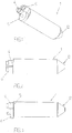
- reference numeral (1) generically denotes a sterile container, for closed circuit processing of a mixture separable into layers, object of the present invention.
- the sterile container (1) can be a test tube or a vial.
- a mixture separable into layers is constituted by a plurality of components which can be solid, liquid or gaseous.
- the sterile container (1) of the present invention is particularly suitable for heterogeneous mixtures which are separable into layers by mechanical separation.
- An example of a mixture separable into layers can be blood or a liquid solution in which bacteria or other cells are suspended.
- sterile container (1) for closed circuit processing is taken to mean that the sterile container (1) is suitable for enabling processing of a mixture separable into layers with no contact with the air, i.e. in sterile conditions and with no risk of contamination of the mixture.
- the collecting of a layer of the mixture separated into layers is preferably carried out in laminar flow conditions (i.e. under a fume hood).
- processing a sterile mixture separable into layers is taken-to-mean, for example, the operations of insertion of a mixture separable into layers internally of the sterile container (1), separation into layers of the mixture separable into layers and removal of the at least a first layer of the mixture separated into layers.
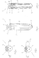
- the sterile container (1) of the present invention comprises a chamber (2) for containing a mixture separable into layers which mixture is separable into at least a first layer and a second layer, and a first opening (3) for placing the chamber (2) in communication with the outside.
- the sterile container (1) further comprises: a second opening (not illustrated) for placing the chamber (2) in communication with the outside; a first connector (4) conformed for coupling to an injection device (for example a syringe lacking a needle), for injection of a mixture separable into layers, and/or a removing device (for example a syringe lacking a needle) for removal of a layer of a mixture separated into layers.
- an injection device for example a syringe lacking a needle
- a removing device for example a syringe lacking a needle
- the first connector (4) is arranged and conformed for enabling the fluid connection, via the first opening (3), between the chamber (2) and the injection device and/or the removing device.
- the sterile container (1) further comprises: a first valve (5) conformed for sealedly closing the first opening (3); a second valve (6) arranged and conformed for enabling exit of air from the chamber (2), when the mixture separable into layers is injected into the chamber (2); a first conduit (7) which is arranged internally of the chamber (2), which is connected to the first opening (3) and which is dimensioned so as to enable the removal of the first layer of the mixture separated into layers.
- the first valve (5) can assume a closed configuration in which it sealedly closes the first opening (3) and an open configuration in which is placed in fluid communication, through the first opening (3), the chamber (2) and the first connector (4).
- the first valve (5) connects the first connector (4) and the first opening (3).
- the first valve (5) can be arranged at the first opening (3).
- the first valve (5) can be a double-acting valve.
- the first valve (5) can comprise a deformable body, for example made of silicone, having a through-hole.
- the first valve (5) is conformed so as assume the open configuration when the injection device is connected to the first connector (4): the connection of the injection device to the first connector (4) determines the deformation of the deformable body of the first valve (5) enabling inlet into the chamber (2) of the mixture separable into layers.
- the first valve (5) returns into the closed configuration, i.e., the deformable body of the first valve (5) will return into the starting condition, preventing the outflow of mixture separable into layers from the chamber (2).
- the first valve (5) will assume the open configuration, enabling removal of the first layer of the mixture separated into layers.
- the second valve (6) is preferably a double-acting valve so as to enable exit of air from the chamber (2), when the mixture separable into layers is injected into the chamber (2), and the inlet of air into the chamber (2), when the first layer of the mixture separated into layers is removed from the chamber (2) (usually the step of removing the layer of the mixture separated into layers is carried out in laminar flow conditions i.e. under a fume hood).
- the second valve (6) does not enable outflow from the chamber (2) of the mixture separable into layers and/or the layers of the mixture separated into layers.
- the first connector (4) can also be conformed -for coupling- to the removing device and the sterile container (1), further comprises: a third opening (8) for placing for placing the chamber (2) in communication with the outside; a second connector (9) arranged and conformed for coupling to the injection device and for enabling fluid connection, via the third opening (8), between the chamber (2) and the injection device; a third valve (10) conformed for sealedly closing the third opening (8).
- the first connector (4) can be conformed for coupling only to the removing device while the second connector (9) can be conformed for coupling only to the injection device.
- the third valve (10) can assume a closed configuration in which it sealedly closes the third opening (8) and an open configuration in which it places in fluid communication, through the third opening (8), the chamber (2) and the second connector (9).
- the third valve (10) connects the second connector (9) and the third opening (8).
- the third valve (10) can be arranged at the third opening (8).
- first valve (5) and the third valve (10) can be single-acting valves.
- the first valve (5) can comprise a deformable body, for example made of silicone, having a through-hole
- the third valve (10) can comprise a deformable body, for example made of silicone, having a through-hole.
- the third valve (10) With the sterile container (1) of the present invention, by connecting the injection device to the second connector (9) the third valve (10) will assume the open configuration, i.e. the deformable body of the third valve (10) will tend to deform and widen the through-hole, enabling inlet into the chamber (2) of the mixture separable into layers.
- the injection device is disconnected from the second connector (9) and the deformable body of the first valve (10) returns into the starting condition, preventing the outflow of mixture separable into layers from the chamber (2) (the third valve (10) will return into the closed configuration).
- the first valve (5) Following the separation into layers of the mixture separable into layers, by connecting the removing device to the first connector (4) the first valve (5) will assume the open configuration, i.e. the deformable body of the first valve (5) will tend to deform, widening the through-hole and enabling outflow of the first layer of the mixture separated into layers from the chamber (2). Lastly, by disconnecting the removing device from the first connector (4) there will be a return of the first valve (5) into the closed configuration.
- the sterile container (1) can comprise a cap (not illustrated) for sealing the exposed end of the first connector (4), when the removing device and/or the injection device is not connected to the first connector (4).
- the second connector (9) is conformed for coupling also to the removing device and wherein the container comprises a second conduit (11) which is arranged internally of the chamber (2), which is connected to the third opening (8) and which is dimensioned so as to enable the removal of the second layer of the mixture separated into layers.
- the second connector (9) can couple both to the injection device and to the removing device: for example, the first connector (4) and the second connector (9) can be conformed for coupling both to respective removal devices for collecting, once the mixture separable into layers is injected into the chamber (2), a plurality of layers of the mixture separated into layers.
- the presence of the second conduit (11) enables being able to remove, from the container, a plurality of layers of the mixture separated into layers, also starting from the layer arranged superiorly. In this way the probability of causing an undesired mixing of the mixture separated into layers is advantageously minimised.
- the sterile container (1) can comprise a main body which forms the chamber (2).
- the main body can be made of rigid PVC. Further, the main body can be conformed as a vial or a test tube.
- the sterile container (1) can comprise a bottom wall (12) and an upper wall (13) opposite the bottom wall (12).
- the first opening (3) and the third opening (8) are preferably made at the upper wall (13).
- first conduit (7) can be longer than the second conduit (11).
- the first conduit (7) preferably has an end (7a) in proximity of the bottom wall (12). This advantageously ensures removal of all the inferiorly-arranged layer.
- the mixture separable into layers is a heterogeneous mixture constituted by a liquid solution and bacteria
- the bacteria will deposit on the bottom, constituting the first layer.
- the end of the first conduit (7) in proximity of the bottom will thus advantageously ensure removal of a sufficient quantity of bacteria.
- the first connector (4) and the second connector (9) can be identical.
- the first valve (5) and the third valve (5) can be identical.
- the following contains a method for processing, in a closed circuit, a mixture separable into layers, object of the present invention.
- the method comprises steps of: providing a sterile container (1) according to the sterile container (1) of the present invention; connecting to the container an injection device of a mixture separable into layers (for example a syringe lacking a needle); injecting a mixture separable into layers into the chamber (2); separating the mixture separable into layers into the at least a first layer and a second layer, the second layer being arranged above the first layer; connecting to the first connector (4) a removing device of a layer of a mixture separated into layers (for example, a syringe lacking a needle); connecting to the second connector (9) a removing device of a layer of a mixture separated into layers (for example, a syringe lacking a needle); removing the second layer of the mixture separated into layers by means of the second connector (9) and the second conduit (11); removing the first layer of the mixture separated into layers by means of the first connector (4) and the first conduit (7).
- the method of the invention advantageously enables processing in a closed circuit a mixture separable into layers without the use of needles.
- the method advantageously enables removing, from the sterile container (1), the first layer and the second layer, minimising the risk of an undesired mixing between them.
- the mixture separable into layers is preferably mechanically injected under pressure into the chamber (2) (for example, using a syringe lacking a needle). Further, the first layer can be removed from the chamber (2) by mechanical aspiration (for example using a syringe lacking a needle).
- the first valve (5) can advantageously be constituted by a simple deformable body, for example made of silicone.
- the second layer can also be removed from the chamber (2) by mechanical aspiration.
- the second valve (6) can also advantageously be constituted by a simple deformable body, for example made of silicone.
- the mixture separable into layers is separated into the at least a first layer and second layer by mechanical separation, for example by centrifugation or precipitation.
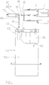
- a system (50) is illustrated for processing, in a closed circuit, a mixture separable into layers which uses a sterile container (1), object of the present invention.
- the system (50) illustrated in figure 8 comprises: a closed circuit sterile device (100) used for collection, transport and processing of a removed infected prosthesis, which sterile device (100) comprises an outlet (101) of a mixture separable into layers; at least a sterile container (1) of the present invention; closed circuit connection means (60) for connecting the outlet (101) of the sterile device (100) to the container.
- the sterile device (100) is known and described in detail in patent application PCT/IT2015/000140 . It comprises a bag (102) which forms a first chamber (103) internally of which the removed prosthesis (not illustrated) is arranged, and a second chamber (104) containing a washing solution.
- the first chamber (103) and the second chamber (104) are separate from one another; they are placed in fluid communication by opening a passage (105) closed by a breakable valve.
- the connection means (60) of the system (50) comprises: a three-way valve (61) comprising a first inlet (61a), a second inlet (61b) and a first outlet (61c); a first conduit (62) which places the outlet (101) of the sterile device (100) and the first inlet (61a) of the three-way valve (61) in fluid connection; a syringe lacking a needle (63) in fluid connection with the second inlet (61b) of the three-way valve (61); a second conduit (64) which places the outlet (61c) of the three-way valve (61) in fluid connection with the first connector (4) of the sterile container (1).
- the three-way valve (61) is designed so that the aspiration by the syringe lacking a needle (63) takes the mixture separable into layers from the first chamber (103) of the bag (102) to inside the syringe lacking a needle (63) and so that the thrust of the syringe lacking a needle (63) pushes the mixture separable into layers from the syringe lacking a needle (63) up to the chamber (2) of the sterile container (1) (passing through the first opening (3)).
- the sterile container (1) is filled with mixture separable into layers.
- the sterile container (1) is detached from the system (50) (in particular from the second conduit (64) of the connection means (60)) and the mixture in layers can be separated.
- the first layer and/or the second layer can be removed.
Landscapes
- Health & Medical Sciences (AREA)
- Chemical & Material Sciences (AREA)
- Analytical Chemistry (AREA)
- General Health & Medical Sciences (AREA)
- Hematology (AREA)
- Clinical Laboratory Science (AREA)
- Chemical Kinetics & Catalysis (AREA)
- Medical Preparation Storing Or Oral Administration Devices (AREA)
- Auxiliary Devices For And Details Of Packaging Control (AREA)
Claims (5)
- Steriler Behälter (1) zur Verarbeitung, in einem geschlossenen Kreis, eines in Schichten trennbaren Gemischs, umfassend:eine Kammer (2) zur Aufnahme eines in Schichten trennbaren Gemischs, wobei das Gemisch in zumindest eine erste Schicht und eine zweite Schicht getrennt werden kann;eine erste Öffnung (3), um die Kammer (2) in Verbindung mit einer Außenumgebung zu setzen;eine zweite Öffnung, um die Kammer (2) in Verbindung mit einer Außenumgebung zu setzen;einen ersten Verbinder (4), der dafür ausgelegt ist, mit einer Injektionsvorrichtung gekoppelt zu werden, um ein in Schichten trennbares Gemisch zu injizieren, und/oder mit einer Entnahmevorrichtung gekoppelt zu werden, um eine Schicht eines in Schichten getrennten Gemisches zu entnehmen;wobei der erste Verbinder (4) so angeordnet und beschaffen ist, dass er die Fluidverbindung, über die erste Öffnung (3), zwischen der Kammer (2) und der Injektionsvorrichtung und/oder der Entnahmevorrichtung ermöglicht;ein erstes Ventil (5), das dafür ausgelegt ist, die erste Öffnung (3) abdichtend zu verschließen;ein zweites Ventil (6), das so angeordnet und beschaffen ist, dass es das Austreten von Luft aus der Kammer (2) ermöglicht, wenn das in Schichten trennbare Gemisch in die Kammer (2) injiziert wird;eine erste Leitung (7), die im Inneren der Kammer (2) angeordnet ist, die mit der ersten Öffnung (3) verbunden ist, und die so bemessen ist, dass sie das Entnehmen der ersten Schicht des in Schichten getrennten Gemischs ermöglicht;wobei der erste Verbinder (4) dafür ausgelegt ist, an die Entnahmevorrichtung gekoppelt zu werden, und der sterile Behälter (1) ferner umfasst:eine dritte Öffnung (8), um die Kammer (2) in Verbindung mit einer Außenumgebung zu setzen;einen zweiten Verbinder (9), der angeordnet und beschaffen ist, um an die Injektionsvorrichtung gekoppelt zu werden und die Fluidverbindung, über die dritte Öffnung (8), zwischen der Kammer (2) und der Injektionsvorrichtung zu ermöglichen;ein drittes Ventil (10), das dafür ausgelegt ist, die dritte Öffnung (8) abdichtend zu verschließen;wobei der zweite Verbinder (9) dafür ausgelegt ist, auch an die Entnahmevorrichtung gekoppelt zu werden, und wobei der Behälter eine zweite Leitung (11) umfasst, die im Inneren der Kammer (2) angeordnet ist, die mit der dritten Öffnung (8) verbunden ist, und die so bemessen ist, dass sie das Entnehmen der zweiten Schicht des in Schichten getrennten Gemischs ermöglicht;eine Bodenwand (12) und eine obere Wand (13), die der Bodenwand (12) gegenüberliegt; wobei die erste Öffnung (3) und die dritte Öffnung (8) in der oberen Wand (13) ausgefertigt sind; wobei die erste Leitung (7) länger ist als die zweite Leitung (11),dadurch gekennzeichnet, dass die erste Leitung (7) und die zweite Leitung (11) schon vor der Verwendung des sterilen Behälters (1) innerhalb der Kammer (2) angeordnet sind.
- Steriler Behälter (1) nach dem vorhergehenden Anspruch, wobei die erste Leitung (7) ein Ende in Nähe der Bodenwand (12) aufweist.
- Verfahren zur Verarbeitung eines in Schichten trennbaren Gemischs in einem geschlossenen Kreis, folgende Schritte umfassend:Bereitstellen eines sterilen Behälters (1) nach einem der vorhergehenden Ansprüche;Anschließen einer Injektionsvorrichtung zum Injizieren eines in Schichten trennbaren Gemischs an den sterilen Behälter (1);Injizieren eines in Schichten trennbaren Gemischs in die Kammer (2);Trennen des in Schichten trennbaren Gemischs in die zumindest eine Schicht und eine zweite Schicht, wobei die zweite Schicht oberhalb der ersten Schicht angeordnet ist;Anschließen einer Entnahmevorrichtung zum Entnehmen einer Schicht eines in Schichten getrennten Gemischs an den ersten Verbinder (4);Anschließen einer Entnahmevorrichtung zum Entnehmen einer Schicht eines in Schichten getrennten Gemischs an den zweiten Verbinder (9);Entnehmen der zweiten Schicht des in Schichten getrennten Gemischs mittels des zweiten Verbinders (9) und der zweiten Leitung (11);Entnehmen der ersten Schicht des in Schichten getrennten Gemischs mittels des ersten Verbinders (4) und der ersten Leitung (7);
- Verfahren nach Anspruch 3, wobei das in Schichten trennbare Gemisch mechanisch unter Druck in die Kammer (2) injiziert wird und wobei die erste Schicht durch mechanische Ansaugung aus der Kammer (2) entnommen wird.
- Verfahren nach einem der vorhergehenden Ansprüche 3 und 4, wobei das in Schichten trennbare Gemisch durch mechanische Separation in die zumindest eine erste Schicht und zweite Schicht getrennt wird.
Applications Claiming Priority (2)
| Application Number | Priority Date | Filing Date | Title |
|---|---|---|---|
| ITUA2016A004258A ITUA20164258A1 (it) | 2016-06-10 | 2016-06-10 | Contenitore sterile per processare in circuito chiuso una miscela separabile in strati e relativo metodo |
| PCT/IB2017/053396 WO2017212436A1 (en) | 2016-06-10 | 2017-06-08 | A sterile container for processing a mixture separable into layers in a closed circuit, and a relative method |
Publications (2)
| Publication Number | Publication Date |
|---|---|
| EP3468717A1 EP3468717A1 (de) | 2019-04-17 |
| EP3468717B1 true EP3468717B1 (de) | 2020-11-18 |
Family
ID=57184631
Family Applications (1)
| Application Number | Title | Priority Date | Filing Date |
|---|---|---|---|
| EP17742540.2A Not-in-force EP3468717B1 (de) | 2016-06-10 | 2017-06-08 | Steriler behälter zur verarbeitung einer in schichten trennbaren mischung in einem geschlossenen kreis und entsprechendes verfahren |
Country Status (4)
| Country | Link |
|---|---|
| US (1) | US20190262823A1 (de) |
| EP (1) | EP3468717B1 (de) |
| IT (1) | ITUA20164258A1 (de) |
| WO (1) | WO2017212436A1 (de) |
Families Citing this family (1)
| Publication number | Priority date | Publication date | Assignee | Title |
|---|---|---|---|---|
| US11904321B2 (en) | 2019-05-30 | 2024-02-20 | Life Technologies Corporation | Fluid interface to receive removable container |
Family Cites Families (4)
| Publication number | Priority date | Publication date | Assignee | Title |
|---|---|---|---|---|
| EP1406492B1 (de) * | 2001-06-06 | 2009-12-30 | Perfusion Partners & Associates, Inc. | Zentrifugenröhrenanordnung |
| ITRM20030467A1 (it) * | 2003-10-10 | 2005-04-11 | Advance Holdings Ltd | Contenitore monouso per la centrifugazione ed il trattamento di un materiale biologico fluido. |
| ITRM20040397A1 (it) * | 2004-08-04 | 2004-11-04 | Univ Roma | Dispositivo monouso per una o piu' introduzioni, trattamento e prelievi di materiale biologico da almeno una delle fasi di separazione, presenti all'interno del dispositivo, in condizioni di sterilita' e a pressione costante. |
| US9120095B2 (en) * | 2012-03-29 | 2015-09-01 | Biomet Biologics, Llc | Apparatus and method for separating and concentrating a component of a fluid |
-
2016
- 2016-06-10 IT ITUA2016A004258A patent/ITUA20164258A1/it unknown
-
2017
- 2017-06-08 WO PCT/IB2017/053396 patent/WO2017212436A1/en not_active Ceased
- 2017-06-08 EP EP17742540.2A patent/EP3468717B1/de not_active Not-in-force
- 2017-06-08 US US16/308,368 patent/US20190262823A1/en not_active Abandoned
Non-Patent Citations (1)
| Title |
|---|
| None * |
Also Published As
| Publication number | Publication date |
|---|---|
| EP3468717A1 (de) | 2019-04-17 |
| ITUA20164258A1 (it) | 2017-12-10 |
| WO2017212436A1 (en) | 2017-12-14 |
| US20190262823A1 (en) | 2019-08-29 |
Similar Documents
| Publication | Publication Date | Title |
|---|---|---|
| CN105392445B9 (zh) | Ivf卵收集室 | |
| CN104470635B (zh) | 样品制备装置 | |
| US3945380A (en) | Plasmapheresis assembly | |
| US20030028156A1 (en) | Fluid connector devices and methods of use | |
| US20020185186A1 (en) | Fluid transfer devices and methods of use | |
| CN106457242B (zh) | 清洁地转移流体的流体转移装置和过程 | |
| EP2475973B1 (de) | Probenahmevorrichtung | |
| SE434700B (sv) | Anordning for lufttet overforing av substans fran ett kerl till ett annat | |
| US20050107765A1 (en) | Sterile sampling methods and apparatus | |
| US11648179B2 (en) | Sealer-less plasma bottle and top for same | |
| CN109152698B (zh) | 无密封件的血浆瓶及其顶盖 | |
| US20190262823A1 (en) | A sterile container for processing a mixture separable into layers in a closed circuit, and a relative method | |
| EP3102668B1 (de) | Vorrichtung zur probenahme und aufbereitung von biomedizinischen proben in einer geschlossenen sterilen umgebung | |
| CN113041700B (zh) | 用于回收流体的方法和系统 | |
| US20210369943A1 (en) | Vessel and device for recovering and preparing adipose tissues | |
| CN112312876B (zh) | 无密封件血浆瓶及其顶盖 | |
| CN116761879A (zh) | 用于液体处理装置的尖头的无菌保护附件 | |
| WO2025051789A1 (en) | Transfer device and transfer method for transferring at least one volume of a cell suspension | |
| HK40043103A (en) | Sealer-less plasma bottle and top for same | |
| HK40002474A (en) | Sealer-less plasma bottle and top for same | |
| HK40002474B (en) | Sealer-less plasma bottle and top for same | |
| CN114127251A (zh) | 多连接器端口 | |
| HK40043103B (zh) | 无密封件血浆瓶及其顶盖 | |
| HK40009710A (en) | Ivf egg collection chamber |
Legal Events
| Date | Code | Title | Description |
|---|---|---|---|
| STAA | Information on the status of an ep patent application or granted ep patent |
Free format text: STATUS: UNKNOWN |
|
| STAA | Information on the status of an ep patent application or granted ep patent |
Free format text: STATUS: THE INTERNATIONAL PUBLICATION HAS BEEN MADE |
|
| PUAI | Public reference made under article 153(3) epc to a published international application that has entered the european phase |
Free format text: ORIGINAL CODE: 0009012 |
|
| STAA | Information on the status of an ep patent application or granted ep patent |
Free format text: STATUS: REQUEST FOR EXAMINATION WAS MADE |
|
| 17P | Request for examination filed |
Effective date: 20181224 |
|
| AK | Designated contracting states |
Kind code of ref document: A1 Designated state(s): AL AT BE BG CH CY CZ DE DK EE ES FI FR GB GR HR HU IE IS IT LI LT LU LV MC MK MT NL NO PL PT RO RS SE SI SK SM TR |
|
| AX | Request for extension of the european patent |
Extension state: BA ME |
|
| DAV | Request for validation of the european patent (deleted) | ||
| DAX | Request for extension of the european patent (deleted) | ||
| STAA | Information on the status of an ep patent application or granted ep patent |
Free format text: STATUS: EXAMINATION IS IN PROGRESS |
|
| GRAP | Despatch of communication of intention to grant a patent |
Free format text: ORIGINAL CODE: EPIDOSNIGR1 |
|
| STAA | Information on the status of an ep patent application or granted ep patent |
Free format text: STATUS: GRANT OF PATENT IS INTENDED |
|
| 17Q | First examination report despatched |
Effective date: 20200527 |
|
| INTG | Intention to grant announced |
Effective date: 20200619 |
|
| GRAS | Grant fee paid |
Free format text: ORIGINAL CODE: EPIDOSNIGR3 |
|
| GRAA | (expected) grant |
Free format text: ORIGINAL CODE: 0009210 |
|
| STAA | Information on the status of an ep patent application or granted ep patent |
Free format text: STATUS: THE PATENT HAS BEEN GRANTED |
|
| AK | Designated contracting states |
Kind code of ref document: B1 Designated state(s): AL AT BE BG CH CY CZ DE DK EE ES FI FR GB GR HR HU IE IS IT LI LT LU LV MC MK MT NL NO PL PT RO RS SE SI SK SM TR |
|
| REG | Reference to a national code |
Ref country code: GB Ref legal event code: FG4D |
|
| REG | Reference to a national code |
Ref country code: CH Ref legal event code: EP |
|
| REG | Reference to a national code |
Ref country code: DE Ref legal event code: R096 Ref document number: 602017027800 Country of ref document: DE |
|
| REG | Reference to a national code |
Ref country code: IE Ref legal event code: FG4D |
|
| REG | Reference to a national code |
Ref country code: AT Ref legal event code: REF Ref document number: 1335146 Country of ref document: AT Kind code of ref document: T Effective date: 20201215 |
|
| REG | Reference to a national code |
Ref country code: AT Ref legal event code: MK05 Ref document number: 1335146 Country of ref document: AT Kind code of ref document: T Effective date: 20201118 |
|
| REG | Reference to a national code |
Ref country code: NL Ref legal event code: MP Effective date: 20201118 |
|
| PG25 | Lapsed in a contracting state [announced via postgrant information from national office to epo] |
Ref country code: NO Free format text: LAPSE BECAUSE OF FAILURE TO SUBMIT A TRANSLATION OF THE DESCRIPTION OR TO PAY THE FEE WITHIN THE PRESCRIBED TIME-LIMIT Effective date: 20210218 Ref country code: PT Free format text: LAPSE BECAUSE OF FAILURE TO SUBMIT A TRANSLATION OF THE DESCRIPTION OR TO PAY THE FEE WITHIN THE PRESCRIBED TIME-LIMIT Effective date: 20210318 Ref country code: RS Free format text: LAPSE BECAUSE OF FAILURE TO SUBMIT A TRANSLATION OF THE DESCRIPTION OR TO PAY THE FEE WITHIN THE PRESCRIBED TIME-LIMIT Effective date: 20201118 Ref country code: FI Free format text: LAPSE BECAUSE OF FAILURE TO SUBMIT A TRANSLATION OF THE DESCRIPTION OR TO PAY THE FEE WITHIN THE PRESCRIBED TIME-LIMIT Effective date: 20201118 Ref country code: GR Free format text: LAPSE BECAUSE OF FAILURE TO SUBMIT A TRANSLATION OF THE DESCRIPTION OR TO PAY THE FEE WITHIN THE PRESCRIBED TIME-LIMIT Effective date: 20210219 |
|
| PG25 | Lapsed in a contracting state [announced via postgrant information from national office to epo] |
Ref country code: BG Free format text: LAPSE BECAUSE OF FAILURE TO SUBMIT A TRANSLATION OF THE DESCRIPTION OR TO PAY THE FEE WITHIN THE PRESCRIBED TIME-LIMIT Effective date: 20210218 Ref country code: IS Free format text: LAPSE BECAUSE OF FAILURE TO SUBMIT A TRANSLATION OF THE DESCRIPTION OR TO PAY THE FEE WITHIN THE PRESCRIBED TIME-LIMIT Effective date: 20210318 Ref country code: LV Free format text: LAPSE BECAUSE OF FAILURE TO SUBMIT A TRANSLATION OF THE DESCRIPTION OR TO PAY THE FEE WITHIN THE PRESCRIBED TIME-LIMIT Effective date: 20201118 Ref country code: PL Free format text: LAPSE BECAUSE OF FAILURE TO SUBMIT A TRANSLATION OF THE DESCRIPTION OR TO PAY THE FEE WITHIN THE PRESCRIBED TIME-LIMIT Effective date: 20201118 Ref country code: SE Free format text: LAPSE BECAUSE OF FAILURE TO SUBMIT A TRANSLATION OF THE DESCRIPTION OR TO PAY THE FEE WITHIN THE PRESCRIBED TIME-LIMIT Effective date: 20201118 Ref country code: AT Free format text: LAPSE BECAUSE OF FAILURE TO SUBMIT A TRANSLATION OF THE DESCRIPTION OR TO PAY THE FEE WITHIN THE PRESCRIBED TIME-LIMIT Effective date: 20201118 |
|
| REG | Reference to a national code |
Ref country code: LT Ref legal event code: MG9D |
|
| PG25 | Lapsed in a contracting state [announced via postgrant information from national office to epo] |
Ref country code: HR Free format text: LAPSE BECAUSE OF FAILURE TO SUBMIT A TRANSLATION OF THE DESCRIPTION OR TO PAY THE FEE WITHIN THE PRESCRIBED TIME-LIMIT Effective date: 20201118 |
|
| PG25 | Lapsed in a contracting state [announced via postgrant information from national office to epo] |
Ref country code: LT Free format text: LAPSE BECAUSE OF FAILURE TO SUBMIT A TRANSLATION OF THE DESCRIPTION OR TO PAY THE FEE WITHIN THE PRESCRIBED TIME-LIMIT Effective date: 20201118 Ref country code: EE Free format text: LAPSE BECAUSE OF FAILURE TO SUBMIT A TRANSLATION OF THE DESCRIPTION OR TO PAY THE FEE WITHIN THE PRESCRIBED TIME-LIMIT Effective date: 20201118 Ref country code: CZ Free format text: LAPSE BECAUSE OF FAILURE TO SUBMIT A TRANSLATION OF THE DESCRIPTION OR TO PAY THE FEE WITHIN THE PRESCRIBED TIME-LIMIT Effective date: 20201118 Ref country code: SM Free format text: LAPSE BECAUSE OF FAILURE TO SUBMIT A TRANSLATION OF THE DESCRIPTION OR TO PAY THE FEE WITHIN THE PRESCRIBED TIME-LIMIT Effective date: 20201118 Ref country code: SK Free format text: LAPSE BECAUSE OF FAILURE TO SUBMIT A TRANSLATION OF THE DESCRIPTION OR TO PAY THE FEE WITHIN THE PRESCRIBED TIME-LIMIT Effective date: 20201118 Ref country code: RO Free format text: LAPSE BECAUSE OF FAILURE TO SUBMIT A TRANSLATION OF THE DESCRIPTION OR TO PAY THE FEE WITHIN THE PRESCRIBED TIME-LIMIT Effective date: 20201118 |
|
| PGFP | Annual fee paid to national office [announced via postgrant information from national office to epo] |
Ref country code: FR Payment date: 20210625 Year of fee payment: 5 Ref country code: IT Payment date: 20210629 Year of fee payment: 5 |
|
| REG | Reference to a national code |
Ref country code: DE Ref legal event code: R097 Ref document number: 602017027800 Country of ref document: DE |
|
| PG25 | Lapsed in a contracting state [announced via postgrant information from national office to epo] |
Ref country code: DK Free format text: LAPSE BECAUSE OF FAILURE TO SUBMIT A TRANSLATION OF THE DESCRIPTION OR TO PAY THE FEE WITHIN THE PRESCRIBED TIME-LIMIT Effective date: 20201118 |
|
| PGFP | Annual fee paid to national office [announced via postgrant information from national office to epo] |
Ref country code: GB Payment date: 20210625 Year of fee payment: 5 |
|
| PLBE | No opposition filed within time limit |
Free format text: ORIGINAL CODE: 0009261 |
|
| STAA | Information on the status of an ep patent application or granted ep patent |
Free format text: STATUS: NO OPPOSITION FILED WITHIN TIME LIMIT |
|
| 26N | No opposition filed |
Effective date: 20210819 |
|
| PG25 | Lapsed in a contracting state [announced via postgrant information from national office to epo] |
Ref country code: NL Free format text: LAPSE BECAUSE OF FAILURE TO SUBMIT A TRANSLATION OF THE DESCRIPTION OR TO PAY THE FEE WITHIN THE PRESCRIBED TIME-LIMIT Effective date: 20201118 Ref country code: AL Free format text: LAPSE BECAUSE OF FAILURE TO SUBMIT A TRANSLATION OF THE DESCRIPTION OR TO PAY THE FEE WITHIN THE PRESCRIBED TIME-LIMIT Effective date: 20201118 |
|
| PG25 | Lapsed in a contracting state [announced via postgrant information from national office to epo] |
Ref country code: SI Free format text: LAPSE BECAUSE OF FAILURE TO SUBMIT A TRANSLATION OF THE DESCRIPTION OR TO PAY THE FEE WITHIN THE PRESCRIBED TIME-LIMIT Effective date: 20201118 |
|
| PGFP | Annual fee paid to national office [announced via postgrant information from national office to epo] |
Ref country code: DE Payment date: 20210708 Year of fee payment: 5 |
|
| PG25 | Lapsed in a contracting state [announced via postgrant information from national office to epo] |
Ref country code: MC Free format text: LAPSE BECAUSE OF FAILURE TO SUBMIT A TRANSLATION OF THE DESCRIPTION OR TO PAY THE FEE WITHIN THE PRESCRIBED TIME-LIMIT Effective date: 20201118 Ref country code: ES Free format text: LAPSE BECAUSE OF FAILURE TO SUBMIT A TRANSLATION OF THE DESCRIPTION OR TO PAY THE FEE WITHIN THE PRESCRIBED TIME-LIMIT Effective date: 20201118 |
|
| REG | Reference to a national code |
Ref country code: CH Ref legal event code: PL |
|
| REG | Reference to a national code |
Ref country code: BE Ref legal event code: MM Effective date: 20210630 |
|
| PG25 | Lapsed in a contracting state [announced via postgrant information from national office to epo] |
Ref country code: LU Free format text: LAPSE BECAUSE OF NON-PAYMENT OF DUE FEES Effective date: 20210608 |
|
| PG25 | Lapsed in a contracting state [announced via postgrant information from national office to epo] |
Ref country code: LI Free format text: LAPSE BECAUSE OF NON-PAYMENT OF DUE FEES Effective date: 20210630 Ref country code: IE Free format text: LAPSE BECAUSE OF NON-PAYMENT OF DUE FEES Effective date: 20210608 Ref country code: CH Free format text: LAPSE BECAUSE OF NON-PAYMENT OF DUE FEES Effective date: 20210630 |
|
| PG25 | Lapsed in a contracting state [announced via postgrant information from national office to epo] |
Ref country code: IS Free format text: LAPSE BECAUSE OF FAILURE TO SUBMIT A TRANSLATION OF THE DESCRIPTION OR TO PAY THE FEE WITHIN THE PRESCRIBED TIME-LIMIT Effective date: 20210318 |
|
| PG25 | Lapsed in a contracting state [announced via postgrant information from national office to epo] |
Ref country code: BE Free format text: LAPSE BECAUSE OF NON-PAYMENT OF DUE FEES Effective date: 20210630 |
|
| REG | Reference to a national code |
Ref country code: DE Ref legal event code: R119 Ref document number: 602017027800 Country of ref document: DE |
|
| GBPC | Gb: european patent ceased through non-payment of renewal fee |
Effective date: 20220608 |
|
| PG25 | Lapsed in a contracting state [announced via postgrant information from national office to epo] |
Ref country code: FR Free format text: LAPSE BECAUSE OF NON-PAYMENT OF DUE FEES Effective date: 20220630 |
|
| PG25 | Lapsed in a contracting state [announced via postgrant information from national office to epo] |
Ref country code: GB Free format text: LAPSE BECAUSE OF NON-PAYMENT OF DUE FEES Effective date: 20220608 Ref country code: DE Free format text: LAPSE BECAUSE OF NON-PAYMENT OF DUE FEES Effective date: 20230103 |
|
| PG25 | Lapsed in a contracting state [announced via postgrant information from national office to epo] |
Ref country code: CY Free format text: LAPSE BECAUSE OF FAILURE TO SUBMIT A TRANSLATION OF THE DESCRIPTION OR TO PAY THE FEE WITHIN THE PRESCRIBED TIME-LIMIT Effective date: 20201118 |
|
| PG25 | Lapsed in a contracting state [announced via postgrant information from national office to epo] |
Ref country code: IT Free format text: LAPSE BECAUSE OF NON-PAYMENT OF DUE FEES Effective date: 20220608 Ref country code: HU Free format text: LAPSE BECAUSE OF FAILURE TO SUBMIT A TRANSLATION OF THE DESCRIPTION OR TO PAY THE FEE WITHIN THE PRESCRIBED TIME-LIMIT; INVALID AB INITIO Effective date: 20170608 |
|
| PG25 | Lapsed in a contracting state [announced via postgrant information from national office to epo] |
Ref country code: MK Free format text: LAPSE BECAUSE OF FAILURE TO SUBMIT A TRANSLATION OF THE DESCRIPTION OR TO PAY THE FEE WITHIN THE PRESCRIBED TIME-LIMIT Effective date: 20201118 |
|
| PG25 | Lapsed in a contracting state [announced via postgrant information from national office to epo] |
Ref country code: TR Free format text: LAPSE BECAUSE OF FAILURE TO SUBMIT A TRANSLATION OF THE DESCRIPTION OR TO PAY THE FEE WITHIN THE PRESCRIBED TIME-LIMIT Effective date: 20201118 |
|
| PG25 | Lapsed in a contracting state [announced via postgrant information from national office to epo] |
Ref country code: MT Free format text: LAPSE BECAUSE OF FAILURE TO SUBMIT A TRANSLATION OF THE DESCRIPTION OR TO PAY THE FEE WITHIN THE PRESCRIBED TIME-LIMIT Effective date: 20201118 |