EP3469185B1 - Traitement et inversion en plusieurs étapes par des outils de détection de corrosion - Google Patents
Traitement et inversion en plusieurs étapes par des outils de détection de corrosion Download PDFInfo
- Publication number
- EP3469185B1 EP3469185B1 EP16912851.9A EP16912851A EP3469185B1 EP 3469185 B1 EP3469185 B1 EP 3469185B1 EP 16912851 A EP16912851 A EP 16912851A EP 3469185 B1 EP3469185 B1 EP 3469185B1
- Authority
- EP
- European Patent Office
- Prior art keywords
- inversion
- pipes
- measurements
- thickness
- concentric pipes
- Prior art date
- Legal status (The legal status is an assumption and is not a legal conclusion. Google has not performed a legal analysis and makes no representation as to the accuracy of the status listed.)
- Active
Links
Images




Classifications
-
- G—PHYSICS
- G01—MEASURING; TESTING
- G01B—MEASURING LENGTH, THICKNESS OR SIMILAR LINEAR DIMENSIONS; MEASURING ANGLES; MEASURING AREAS; MEASURING IRREGULARITIES OF SURFACES OR CONTOURS
- G01B7/00—Measuring arrangements characterised by the use of electric or magnetic techniques
- G01B7/02—Measuring arrangements characterised by the use of electric or magnetic techniques for measuring length, width or thickness
- G01B7/06—Measuring arrangements characterised by the use of electric or magnetic techniques for measuring length, width or thickness for measuring thickness
-
- E—FIXED CONSTRUCTIONS
- E21—EARTH OR ROCK DRILLING; MINING
- E21B—EARTH OR ROCK DRILLING; OBTAINING OIL, GAS, WATER, SOLUBLE OR MELTABLE MATERIALS OR A SLURRY OF MINERALS FROM WELLS
- E21B47/00—Survey of boreholes or wells
- E21B47/002—Survey of boreholes or wells by visual inspection
-
- E—FIXED CONSTRUCTIONS
- E21—EARTH OR ROCK DRILLING; MINING
- E21B—EARTH OR ROCK DRILLING; OBTAINING OIL, GAS, WATER, SOLUBLE OR MELTABLE MATERIALS OR A SLURRY OF MINERALS FROM WELLS
- E21B47/00—Survey of boreholes or wells
- E21B47/002—Survey of boreholes or wells by visual inspection
- E21B47/0025—Survey of boreholes or wells by visual inspection generating an image of the borehole wall using down-hole measurements, e.g. acoustic or electric
-
- E—FIXED CONSTRUCTIONS
- E21—EARTH OR ROCK DRILLING; MINING
- E21B—EARTH OR ROCK DRILLING; OBTAINING OIL, GAS, WATER, SOLUBLE OR MELTABLE MATERIALS OR A SLURRY OF MINERALS FROM WELLS
- E21B47/00—Survey of boreholes or wells
- E21B47/006—Detection of corrosion or deposition of substances
-
- E—FIXED CONSTRUCTIONS
- E21—EARTH OR ROCK DRILLING; MINING
- E21B—EARTH OR ROCK DRILLING; OBTAINING OIL, GAS, WATER, SOLUBLE OR MELTABLE MATERIALS OR A SLURRY OF MINERALS FROM WELLS
- E21B47/00—Survey of boreholes or wells
- E21B47/08—Measuring diameters or related dimensions at the borehole
-
- E—FIXED CONSTRUCTIONS
- E21—EARTH OR ROCK DRILLING; MINING
- E21B—EARTH OR ROCK DRILLING; OBTAINING OIL, GAS, WATER, SOLUBLE OR MELTABLE MATERIALS OR A SLURRY OF MINERALS FROM WELLS
- E21B47/00—Survey of boreholes or wells
- E21B47/09—Locating or determining the position of objects in boreholes or wells, e.g. the position of an extending arm; Identifying the free or blocked portions of pipes
- E21B47/092—Locating or determining the position of objects in boreholes or wells, e.g. the position of an extending arm; Identifying the free or blocked portions of pipes by detecting magnetic anomalies
-
- E—FIXED CONSTRUCTIONS
- E21—EARTH OR ROCK DRILLING; MINING
- E21B—EARTH OR ROCK DRILLING; OBTAINING OIL, GAS, WATER, SOLUBLE OR MELTABLE MATERIALS OR A SLURRY OF MINERALS FROM WELLS
- E21B47/00—Survey of boreholes or wells
- E21B47/10—Locating fluid leaks, intrusions or movements
- E21B47/113—Locating fluid leaks, intrusions or movements using electrical indications; using light radiations
-
- G—PHYSICS
- G01—MEASURING; TESTING
- G01B—MEASURING LENGTH, THICKNESS OR SIMILAR LINEAR DIMENSIONS; MEASURING ANGLES; MEASURING AREAS; MEASURING IRREGULARITIES OF SURFACES OR CONTOURS
- G01B7/00—Measuring arrangements characterised by the use of electric or magnetic techniques
- G01B7/12—Measuring arrangements characterised by the use of electric or magnetic techniques for measuring diameters
-
- G—PHYSICS
- G01—MEASURING; TESTING
- G01B—MEASURING LENGTH, THICKNESS OR SIMILAR LINEAR DIMENSIONS; MEASURING ANGLES; MEASURING AREAS; MEASURING IRREGULARITIES OF SURFACES OR CONTOURS
- G01B7/00—Measuring arrangements characterised by the use of electric or magnetic techniques
- G01B7/12—Measuring arrangements characterised by the use of electric or magnetic techniques for measuring diameters
- G01B7/13—Internal diameters
-
- G—PHYSICS
- G01—MEASURING; TESTING
- G01V—GEOPHYSICS; GRAVITATIONAL MEASUREMENTS; DETECTING MASSES OR OBJECTS; TAGS
- G01V13/00—Manufacturing, calibrating, cleaning, or repairing instruments or devices covered by groups G01V1/00 – G01V11/00
-
- G—PHYSICS
- G01—MEASURING; TESTING
- G01V—GEOPHYSICS; GRAVITATIONAL MEASUREMENTS; DETECTING MASSES OR OBJECTS; TAGS
- G01V3/00—Electric or magnetic prospecting or detecting; Measuring magnetic field characteristics of the earth, e.g. declination, deviation
- G01V3/18—Electric or magnetic prospecting or detecting; Measuring magnetic field characteristics of the earth, e.g. declination, deviation specially adapted for well-logging
-
- G—PHYSICS
- G01—MEASURING; TESTING
- G01N—INVESTIGATING OR ANALYSING MATERIALS BY DETERMINING THEIR CHEMICAL OR PHYSICAL PROPERTIES
- G01N27/00—Investigating or analysing materials by the use of electric, electrochemical, or magnetic means
- G01N27/72—Investigating or analysing materials by the use of electric, electrochemical, or magnetic means by investigating magnetic variables
- G01N27/82—Investigating or analysing materials by the use of electric, electrochemical, or magnetic means by investigating magnetic variables for investigating the presence of flaws
- G01N27/90—Investigating or analysing materials by the use of electric, electrochemical, or magnetic means by investigating magnetic variables for investigating the presence of flaws using eddy currents
- G01N27/904—Investigating or analysing materials by the use of electric, electrochemical, or magnetic means by investigating magnetic variables for investigating the presence of flaws using eddy currents with two or more sensors
Definitions
- a network of wells, installations and other conduits may be established by connecting sections of metal pipe together.
- a well installation may be completed, in part, by lowering multiple sections of metal pipe (i.e., a casing string) into a borehole, and cementing the casing string in place.
- multiple casing strings are employed (e.g., a concentric multi-string arrangement) to allow for different operations related to well completion, production, or enhanced oil recovery (EOR) options.
- Corrosion of metal pipes is an ongoing issue. Efforts to mitigate corrosion include use of corrosion-resistant alloys, coatings, treatments, and corrosion transfer, among others. Also, efforts to improve corrosion monitoring are ongoing. For downhole casing strings, various types of corrosion monitoring tools are available.
- One type of corrosion detection tool uses electromagnetic (EM) fields to estimate pipe thickness or other corrosion indicators.
- EM electromagnetic
- an EM logging tool may collect EM log data, where the EM log data may be interpreted to correlate a level of flux leakage or EM induction with corrosion.
- correctly managing corrosion detection EM logging tool operations and data interpretation may be complex.
- US2016/0187523 discloses focused symmetric pipe inspection tools.
- the first aspect of the invention is defined by a method according to independent claim 1.
- the second aspect of the invention is defined by a method according to claim 7.
- the third aspect of the invention is defined by a system according to claim 14. Preferred further embodiments are described in the dependent claims.
- This disclosure may generally relate to electromagnetic pipe inspection, and, in some examples, to systems and methods for a multistage workflow for processing and inversion of data collected by corrosion detection tools.
- Systems and methods of the present disclosure may include applying inversion in stages where the output from the first stage may be used to determine which pipe should be selected for computing the impulse response to be used in vertical resolution enhancement deconvolution.
- the deconvolved responses may be used as inputs to the second inversion stage.
- Parameters of the pipes estimated from the first inversion stage to have small thickness changes from the nominal, are constrained in the second inversion stage to allow for more accurate thickness estimations of other pipes.
- the processing and inversion may produce a log of the thickness of each pipe from voltage logs recorded at different receivers and different frequencies. From the thickness log, defected sections in each pipe, the size of the defect, and the amount of metal loss may be estimated.
- the multistage workflow may comprise running a first inversion in which a first subset of calibrated measurements may be used to compute a first estimate of the properties (diameter, thickness, and possibly magnetic permeability and electrical conductivity) of each pipe. Based on the result of the first inversion, proper deconvolution may be applied to the measurements to remove the ghost effect (also known as double indication of features) and also to improve the vertical resolution of the measurements.
- a second inversion may be run in which at least one of the properties of a subset of pipes, determined based on the results of the first inversion, may be constrained; and the deconvolved measurements may be used to compute the thicknesses of all the pipes. Results from the second inversion may be displayed as the final inversion results.
- the disclosed multistage inversion workflow may be particularly important in cases involving overlapping defects on multiple pipes.
- Certain methods for downhole corrosion detection may involve running corrosion detection tools in the production tubing.
- Different types of corrosion detection tools may include mechanical calipers, ultrasonic acoustic tools, cameras, electromagnetic flux leakage, and electromagnetic induction tools.
- electromagnetic induction tools may be used to determine and differentiate corrosion in separate casings beyond that in which the tool is run.
- Existing electromagnetic induction corrosion detection tools may comprise at least one transmitting coil and at least one receiving coil. The transmitter may generate a primary field that may induce eddy currents inside the metallic pipes, and the receiver may record secondary fields generated by the pipes.
- Electromagnetic induction tools may be frequency-domain (FD) tools that may operate at a discrete set of frequencies (higher frequencies to inspect inner pipes and lower frequencies to inspect outer pipes).
- EM induction tools may operate in time-domain (TD) by transmitting transient pulses and measuring the decay response versus time (earlier time corresponds to inner pipes and later time corresponds to outer pipes). These tools may be referred to as pulsed eddy current corrosion detection tools.
- model-based inversion may be needed to estimate the physical and/or electrical properties of each pipe in the casing string from measured responses.
- Model-based inversion may aim at finding the optimum diameter, thickness and the relative permeability of each pipe that may minimize the misfit between measurements and synthetic data generated using a computer model that simulates the tool and the well casings. Inversion may start from an initial guess of model parameters and may iteratively refine that guess until a convergence criterion is met. Constraints may be used to verify that estimated parameters lie within their physical ranges. Regularization may be used to penalize large variations of model parameters from a nominal that is available a-priori.
- Optimum selection of receivers and frequencies to be used in inversion may be based on the configuration (e.g., number of pipes in the string, their nominal thickness, etc.). Prior to inversion, some processing steps may need to be applied. These may include calibration, resolution enhancement and/or log depth alignment, and filtering to improve the signal-to-noise ratio.
- FIG. 1 illustrates an operating environment for a corrosion detection tool 100 as disclosed herein.
- Corrosion detection tool 100 may comprise transmitter 102 (e.g., coil) and receivers 104a, 104b, 104c, 104d, 104e, and 104f (e.g., coil receivers).
- Corrosion detection tool 100 may be operatively coupled to a conveyance line 106 (e.g., wireline, slickline, coiled tubing, pipe, or the like) which may provide mechanical suspension, as well as electrical connectivity, for corrosion detection tool 100.
- Conveyance line 106 and corrosion detection tool 100 may extend within casing string 108 to a desired depth within the wellbore 110.
- Conveyance line 106 which may include one or more electrical conductors, may exit wellhead 112, may pass around pulley 114, may engage odometer 116, and may be reeled onto winch 118, which may be employed to raise and lower the tool assembly in the wellbore 110.
- Signals recorded by corrosion detection tool 100 may be stored on memory and then processed by display and storage unit 120 after recovery of corrosion detection tool 100 from wellbore 110. Alternatively, signals recorded by corrosion detection tool 100 may be conducted to display and storage unit 120 by way of conveyance line 106.
- Display and storage unit 120 may process the signals, and the information contained therein may be displayed for an operator to observe and stored for future processing and reference.
- Display and storage unit 120 may also contain an apparatus for supplying control signals and power to the downhole tool assembly, wherein the downhole tool assembly comprises corrosion detection tool 100.
- a typical casing string 108 may extend from wellhead 112 at or above ground level to a selected depth within a wellbore 110.
- Casing string 108 may comprise a plurality of joints or segments of casing, each segment being connected to the adjacent segments by a threaded collar.
- FIG. 1 also illustrates a typical pipe string 122, which may be positioned inside of casing string 108 extending part of the distance down wellbore 110.
- Pipe string 122 may be production tubing, casing, or other pipe disposed within casing string 108.
- a packer 124 typically may seal the lower end of the tubing-casing annulus and may secure the lower end of the tubing string 122 to the casing.
- the corrosion detection tool 100 may be dimensioned so that it may be lowered into the wellbore 110 through the tubing string 122, thus avoiding the difficulty and expense associated with pulling the tubing string 122 out of the well.
- a digital telemetry system may be employed, wherein an electrical circuit may be used to both supply power to the corrosion detection tool 100 and to transfer data between display and storage unit 120 and corrosion detection tool 100.
- a DC voltage may be provided to the corrosion detection tool 100 by a power supply located above ground level, and data may be coupled to the DC power conductor by a baseband current pulse system.
- the corrosion detection tool 100 may be powered by batteries located within the downhole tool assembly, and/or the data provided by the corrosion detection tool 100 may be stored within the downhole tool assembly, rather than transmitted to the surface during logging (corrosion detection).
- Transmission of electromagnetic fields by the transmitter 102 and the recordation of signals by the receivers 104a, 104b, 104c, 104d, 104e, and 104f may be controlled by an information handling system.
- An information handling system may include any instrumentality or aggregate of instrumentalities operable to compute, estimate, classify, process, transmit, receive, retrieve, originate, switch, store, display, manifest, detect, record, reproduce, handle, or utilize any form of information, intelligence, or data for business, scientific, control, or other purposes.
- an information handling system may be a personal computer, a network storage device, or any other suitable device and may vary in size, shape, performance, functionality, and price.
- the information handling system may include random access memory (RAM), one or more processing resources such as a central processing unit (CPU) or hardware or software control logic, ROM, and/or other types of nonvolatile memory.
- Additional components of the information handling system may include one or more disk drives, one or more network ports for communication with external devices as well as various input and output (I/O) devices, such as a keyboard, a mouse, and a video display.
- the information handling system may also include one or more buses operable to transmit communications between the various hardware components.
- Non-transitory computer-readable media may include any instrumentality or aggregation of instrumentalities that may retain data and/or instructions for a period of time.
- Non-transitory computer-readable media may include, for example, without limitation, storage media such as a direct access storage device (e.g., a hard disk drive or floppy disk drive), a sequential access storage device (e.g., a tape disk drive), compact disk, CD-ROM, DVD, RAM, ROM, electrically erasable programmable read-only memory (EEPROM), and/or flash memory; as well as communications media such wires, optical fibers, microwaves, radio waves, and other electromagnetic and/or optical carriers; and/or any combination of the foregoing.
- storage media such as a direct access storage device (e.g., a hard disk drive or floppy disk drive), a sequential access storage device (e.g., a tape disk drive), compact disk, CD-ROM, DVD, RAM, ROM, electrically erasable programmable read-only memory (EEPROM), and/or flash memory
- communications media such wires, optical fibers, microwaves, radio waves, and other electromagnetic and/or optical carriers; and/or
- FIG. 2 schematically illustrates a workflow of the proposed multistage inversion.
- Box 200 provides running a corrosion detection tool 100 inside a plurality of concentric pipes and making a log.
- Box 202 provides stacking a number of log points in a buffer of a pre-determined size.
- Box 204 provides calibrating the log.
- Box 206 provides running a first inversion in which a first subset of calibrated measurements is used to compute a first estimate of the properties (e.g., diameter, thickness, magnetic permeability and/or electrical conductivity) of each pipe.
- Box 208 provides identifying pipes with thickness change from the pre-known nominal thickness.
- Box 210 provides selecting the innermost pipe with thickness change as the pipe to be used in computing an impulse response for deconvolution.
- Box 212 provides applying deconvolution to a second subset of measurements.
- Box 214 provides running a second inversion in which at least one of the properties of a subset of pipes, determined based on the results of the first inversion, are constrained; and the deconvolved second subset of measurements is used to compute the thickness of all the pipes.
- Box 216 provides displaying the result of the second inversion as the final inversion result.
- the workflow may involve the following steps: 1) After the tool is run inside the cased well, log points may be stacked in an input data buffer. The buffered log may correspond to one or more casing joints. 2) When the buffer is full, the buffered log may be calibrated to compensate for any discrepancy between the real tool and the synthetic model used to invert the measurements.
- a first subset of the calibrated measurements may be used to compute a first estimate of the properties of each pipe.
- Those properties may include the diameter and thickness of the pipe, and possibly, the magnetic permeability and the electrical conductivity.
- the first subset preferably may include coils with small ghost effect, i.e., data from receivers relatively close to the transmitter.
- pipes with thickness change from the nominal may be identified by comparing the percentage change in estimated pipe thickness from the pre-known nominal to a pre-defined threshold; this threshold may be different for each pipe in the configuration, with inner pipes having a smaller threshold and deeper pipes having a larger threshold.
- any section with 10% change in thickness along the log may be identified as a feature.
- Those features may be defects amounting to thickness loss or casing collars or other fixtures amounting to thickness gain.
- the response of the tool to a small defect on the innermost pipe with features may be computed using a computer model.
- This small defect may have any arbitrary shape with its length being as small as possible along the axial direction, but its response being measureable with sufficient accuracy with the tool.
- the geometry of the pipes (number of pipes, their outer diameters, and nominal thickness) as well as their electrical and magnetic properties may need to be approximately known.
- the magnetic permeabilities may not be precisely known and can vary significantly from one casing section to another.
- the average permeability and conductivity estimated from the calibration process can therefore be used in the synthetic model.
- the response to the defect computed from the previous step may be deconvolved from the measured responses, or a subset of which, to eliminate the ghost effect and improve the resolution of the measurements. ghost effect may be especially pronounced in long spacing receivers in frequency-domain tools.
- a method for improving the resolution of the logs and removing ghost effect may be based on deconvolving the impulse response of the tool from measured responses to get resolution-enhanced responses from which defects may be better visualized and interpreted.
- a second inversion may be run in which at least one of the properties of a subset of pipes, determined based on the results of the first inversion, may be constrained to be close to the determined value in the first inversion; and the deconvolved second subset of measurements may be used to compute the thicknesses of all the pipes.
- Results of the second inversion may be taken as the final inversion result.
- the above workflow may be repeated in more than 2 stages if needed, where the inversion result from each stage may be used to constraint a subset of model parameters in the following stage.
- a method for estimating the thickness of individual pipes in a multi-string pipe configuration through processing array measurements made by corrosion detection tools may comprise: 1) Making a log measurement with corrosion detection tool 100 which may comprise at least one transmitter coil (e.g., transmitter 102) and at least one receiver coil (e.g., receivers 104a, 104b, 104c, 104d, 104e, and 104f) and runs inside strings of multiple nested conductive pipes. 2) Calibrating the log by matching the nominal value of the measured response to a synthetic response computed by modeling the pipes with their nominal thicknesses.
- transmitter coil e.g., transmitter 102
- receiver coil e.g., receivers 104a, 104b, 104c, 104d, 104e, and 104f
- a first subset of calibrated measurements may be used to compute a first estimate of the properties (e.g., thickness, and possibly magnetic permeability and electrical conductivity) of each pipe.
- the first subset of calibrated measurements may comprise short-spaced receivers or may comprise all receivers. Short-spaced receivers may include a distance of 30 in. (76 cm) or less.
- Identifying pipes with estimated thickness changes from the nominal by comparing the percentage change in estimated pipe thickness from the nominal to a pre-defined threshold, which may be different for each pipe. 5) Picking the innermost pipe with thickness change as the pipe to be used in computing an impulse response for deconvolution. 6) Applying deconvolution to a second subset of measurements.
- the second subset of measurements may comprise long-spaced receivers or may comprise all receivers. Long-spaced receivers may include a distance of more than 30 in. (76 cm) 7) Running a second inversion in which at least one of the properties of a subset of pipes, determined based on the results of the first inversion, are constrained; and the deconvolved second subset of measurements may be used to compute the thicknesses of all the pipes. 8) Display the result of the second inversion as the final inversion result. 9) The constraint may comprise fixing the thickness of the pipes identified to have nominal thickness from the first inversion. 10) The constraint may comprise fixing the thickness of the innermost pipe in addition to the thickness of pipes identified to have nominal thickness from the first inversion.
- the constraint may comprise fixing the thickness of the innermost pipes up to and including the innermost pipe identified to have thickness change from the first inversion. 12) The constraint may comprise fixing the magnetic permeability of the pipes in the second inversion to the values computed in the first inversion. 13) The constraint may comprise taking results of the first inversion as an initial condition for the second inversion and allowing change within a fixed range only. 14) The constraint may comprise taking results of the first inversion as an initial condition for the second inversion and allowing change, but using a large weight to heavily penalize a departure from an initial value. 15) The above workflow may be repeated in more than 2 stages if needed, where the inversion result from each stage may be used to constraint a subset of model parameters in the following stage. 16) The disclosed method may also apply to both frequency-domain and time-domain corrosion detection tools 100.
- Inversion may be applied point-by-point to the log. Inversion may start from an initial guess of the model parameters (thickness and relative permeability of each pipe) and may iteratively refine model parameters to minimize the misfit between measurements and synthetic data.
- a parametric function (or cost function) may be formed from the linear combination of a misfit function and a stabilizing function (also known as the regularization term).
- the misfit function may be formed as the L2 norm of the weighted difference between observed (measured) and predicted (synthetically computed from the model) data.
- the stabilizing function may be formed as the L0.5, L1 or L2 norm of the weighted model parameters, and may be inclusive of a priori models and spatial functions.
- the model parameters may be iteratively adjusted, subject to preset constraints, to minimize the parametric functional. Constraints may be used to ensure that model parameters output from the inversion process lie within their physical ranges. In each iteration of the minimization process, convergence may be checked through pre-defined termination criteria. These criteria may include the following: (a) cost function is less than a specified tolerance; (b) change in model parameters is less than a specified tolerance; (c) change in the cost function is less than a specified tolerance; (d) Magnitude of search direction is smaller than a specified tolerance; (e) number of iterations exceeded a specified maximum.
- Numerical techniques to achieve this minimization may include deterministic methods (e.g., Gauss-Newton, Trust-Region-Reflective, Levenverg-Marquardt, Steepest Descent, and Conjugate Gradients) or stochastic methods (e.g., Markov Chain Monte Carlo, Genetic Algorithms, and Simulated Annealing).
- deterministic methods e.g., Gauss-Newton, Trust-Region-Reflective, Levenverg-Marquardt, Steepest Descent, and Conjugate Gradients
- stochastic methods e.g., Markov Chain Monte Carlo, Genetic Algorithms, and Simulated Annealing
- the inversion may generate inversion metrics such as misfit/error, data uncertainty estimates, and model uncertainty estimates.
- numerical differentiation may be used to compute the gradient (partial derivatives with respect to each one of the model parameters).
- Analytical differentiation may also be used if analytical expressions relating responses to model parameters are known.
- the forward model may be a 1-dimensional or 2-dimensional computer model that may be evoked on-the-fly within the minimization process, or it may be a pre-computed database. If a database is used, multi-dimensional interpolation may be needed to compute the response corresponding to any given set of model parameters. In either case, the model that is used in inversion may be identical to that that may have been used in calibration.
- the misfit function may be formed as the L2 norm squared of the weighted difference between calibrated measurements m and data predicted by the synthetic model s(x).
- the stabilizing function may be formed as the L1 norm of the weighted difference between model parameters (thickness and relative magnetic permeability of each pipe) x and the nominal model parameters, x 0 . This way, regularization may penalize large variations of thicknesses from nominal. This may help mitigate non-uniqueness problems that may arise in cases involving large number of pipes (e.g., 4 pipes and more).
- the misfit function may be normalized by the number of measurements 2M to make the cost function independent of the number of measurements.
- unrestricted inversion The systems and methods in which the thickness and permeability of all pipes are solved for may be known as unrestricted inversion.
- a restricted problem may be solved where only a subset of the model parameters are assumed to be unknown while others are assumed to have pre-known values.
- a variant of this last case may be the case in which a subset of values may be assumed to be pre-known but changes may still be allowed but may be heavily penalized by the regularization term.
- unrestricted inversion may yield a solution that best fits measured responses due to an increased number of degrees of freedom (model parameters).
- restricted inversion may be needed to reduce the number of unknowns.
- Different forms of restricted inversion may include: 1) Solve for the individual thickness of each pipe, the magnetic permeability of the innermost pipe, and one magnetic permeability common to all other pipes. 2) Solve for the individual thickness of each pipe and one magnetic permeability common to all pipes. 3) Solve for the individual thickness of each pipe and correct the permeability of all pipes to the average value estimated from the calibration step.
- Regularization may be used to penalize (or constraint) changes of some model parameters in the second inversion stage from their values estimated in the first stage.
- These constraints may take any of the following forms: 1) The constraint may comprise increasing the regularization weights of the thickness of the pipes identified to have nominal thickness from the first inversion. 2) The constraint may comprise increasing the regularization weights of the thickness of the innermost pipe in addition to the thickness of pipes identified to have nominal thickness from the first inversion. 3) The constraint may comprise increasing the regularization weights of the thickness of the innermost pipes up to and including the innermost pipe identified to have a thickness change from the first inversion. In addition to any of the above, the constraint may comprise correcting the magnetic permeability of the pipes in the second inversion to the values computed in the first inversion.
- lower and upper bounds may be defined for each model parameter. These bounds may be different in the first and second inversion stages.
- Model parameters may be constrained to physical ranges to eliminate any non-physical results.
- the thickness may range from zero to slightly larger than the nominal thickness to account for defects and pipe variations around the nominal in sections where no collars are expected. In other sections where collars may be expected, the thickness may range from zero to the nominal pipe thickness, plus the nominal collar thickness.
- the relative magnetic permeability may range from ⁇ min to ⁇ max with the limits chosen depending on the a priori knowledge of the type of steel of the pipes used.
- Eq. (3) describes a non-linear least square constrained optimization problem. It may be solved in many ways, including gradient-based and non-gradient-based methods.
- FIG. 3 is a schematic illustration of the corrosion detection tool 100.
- the corrosion detection tool 100 may include one transmitting coil (e.g., transmitter 102), and six receiving coils (e.g., receivers 104a, 104b, 104c, 104d, 104e, and 1041).
- the transmitter 102 may have a core with any suitable relative permeability, conductivity, and outer diameter.
- the receivers 104a, 104b, 104c, 104d, 104e, and 104f may be without a core.
- the corrosion detection tool 100 may be run into concentric pipes disposed in a wellbore 110 (e.g., FIG. 1 ) and used to obtain measurements.
- the concentric pipes may include 2 or more concentric pipes, including 2 concentric pipes, 3 concentric pipes, 4 concentric pipes, 5 concentric pipes, or more.
- the measurements may be obtained at a variety of frequencies as will be appreciated by those of ordinary skill in the art, with the benefit of this disclosure.
- the transmitter 102 may have a relative permeability of about 200 H/m, conductivity of about 0.01 S/m, and OD (outer diameter) of about 0.8 in (2 cm).
- the receivers 104a, 104b, 104c, 104d, 104e, and 104f may be without a core.
- measurements may be performed at the following frequencies: f 1 , f 2 , f 3 and f 4 , and the corrosion detection tool 100 may be run inside 5 concentric pipes. Parameters of the pipes, for this example, are summarized in Table 1.
- the 4th pipe has three 2-ft (0.6 m) defects while the 5 th pipe has a large, 6-ft (1.8 m) long defect and a smaller 1-ft (0.3 m) defect adjacent to it as shown in Table 1.
- Table 1 Parameters of the pipes.
- a radial 1D (R-1D) model is used in the inversion.
- raw measurements are calibrated to match the synthetic response at a nominal section of the log.
- Estimates of the average electrical conductivity and the average magnetic permeability of all pipes are also obtained during the calibration step.
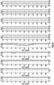
- Calibrated responses for all receivers 104a, 104b, 104c, 104d, 104e, and 104f and frequencies are shown in FIGS. 4A and 4B .
- Each frequency/receiver log may be normalized to the point that has the minimum magnitude.
- FIG. 4A illustrates the raw magnitude response.
- FIG. 4B illustrates the raw phase response.
- receivers 104a, 104b and 104c are used.
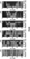
- the inversion results of this first stage for this example are shown in FIG. 5 .
- the inversion is be used to solve for the thickness of each pipe, the magnetic permeability of the innermost pipe, and one magnetic permeability common to all other pipes.
- Inversion is used to capture the depth and thickness of the defects on the 4th and 5th pipes while estimating the thickness of non-defected inner pipes reasonably accurately.
- ghost effects due to the defects in pipe 4 are visible in the outermost pipe (at ⁇ 3ft (0.9 m) and ⁇ 15ft (4.5 m)). This may cause the detection of spurious defects.
- the example continues with the resolution of the responses enhanced using deconvolution in the second stage.
- the 4th pipe is chosen to calculate the deconvolution response since this pipe shows as the innermost pipe, in this example, with a defect in the first stage of inversion.
- Magnitude and phase of the resolution enhanced responses, for this example, are shown in FIGS. 6A and 6B .
- FIGS. 6A and 6B compared with the original responses shown in FIGS. 4A and 4B , peaks of the resolution enhanced responses are better aligned with the location of the defects.
- Using the resolution enhanced responses of receivers 104e and 104f (e.g., shown on FIG.
- FIG. 7 shows the final inversion results, for this example, after the second stage.
- ghost effect is significantly reduced and thickness estimates of the defected regions on the 5 th pipe are improved.
- this example continues with reconstructions responses corresponding to the inverted parameters using the R1D model and compared with the measured responses, as shown in FIG. 8 .
- an accurate fit is observed at all receivers 104 (e.g., receivers 104a, 104b, 104c, 104d, 104e, and 104f shown on FIG. 3 ).
Landscapes
- Physics & Mathematics (AREA)
- Life Sciences & Earth Sciences (AREA)
- Engineering & Computer Science (AREA)
- Geology (AREA)
- Mining & Mineral Resources (AREA)
- Geophysics (AREA)
- General Life Sciences & Earth Sciences (AREA)
- Environmental & Geological Engineering (AREA)
- Fluid Mechanics (AREA)
- Geochemistry & Mineralogy (AREA)
- General Physics & Mathematics (AREA)
- Manufacturing & Machinery (AREA)
- Remote Sensing (AREA)
- Investigating Or Analyzing Materials By The Use Of Magnetic Means (AREA)
- Length-Measuring Devices Using Wave Or Particle Radiation (AREA)
Claims (14)
- Procédé comprenant :la disposition d'un outil de détection de corrosion (100) dans une pluralité de tuyaux concentriques, dans lequel l'outil de détection de corrosion (100) comprend un émetteur (102) et une pluralité de récepteurs (104a, 104b, 104c, 104d, 104e, 104f) ;la réalisation d'une mesure de diagraphie avec l'outil de détection de corrosion (100) en mesurant un signal pour fournir une réponse mesurée ;l'étalonnage du journal, dans lequel l'étalonnage comprend la mise en correspondance d'une valeur nominale de la réponse mesurée avec une réponse synthétique pour fournir des mesures étalonnées, dans lequel ladite réponse synthétique est calculée en modélisant les tuyaux concentriques avec leurs épaisseurs nominales ;l'exécution d'une première inversion, dans lequel la première inversion comprend l'étape d'utilisation d'un premier sous-ensemble des mesures étalonnées pour calculer une première estimation des propriétés de chacun des tuyaux concentriques ;l'identification de tuyaux avec un changement d'épaisseur estimé à partir d'une épaisseur nominale pour fournir des tuyaux concentriques identifiés ;la sélection d'un tuyau concentrique le plus à l'intérieur parmi les tuyaux concentriques identifiés pour calculer une réponse impulsionnelle de l'outil de détection de corrosion (100) à un petit défaut sur ledit tuyau le plus à l'intérieur pour une déconvolution afin d'améliorer la résolution verticale de la réponse mesurée ;l'application d'une déconvolution à un second sous-ensemble des mesures étalonnées pour fournir des mesures étalonnées et déconvoluées ; etl'exécution d'une seconde inversion sur le second sous-ensemble de mesures étalonnées et déconvoluées, dans lequel la seconde inversion comprend au moins une propriété de la pluralité de tuyaux concentriques.
- Procédé selon la revendication 1, dans lequel les propriétés de la première estimation comprennent l'épaisseur, le diamètre interne, le diamètre externe, la perméabilité magnétique ou la conductivité électrique, et dans lequel le premier sous-ensemble des mesures étalonnées comprennent des mesures provenant de récepteurs peu espacés ou des mesures provenant de tous les récepteurs (104a, 104b, 104c, 104d, 104e, 104f).
- Procédé selon l'une quelconque des revendications 1 à 2, comprenant en outre le calcul de la réponse synthétique en modélisant les tuyaux concentriques avec leurs épaisseurs nominales.
- Procédé selon l'une quelconque des revendications 1 à 3, dans lequel l'identification comprend la comparaison d'un changement en pourcentage de l'épaisseur estimée du tuyau à partir de l'épaisseur nominale à un seuil prédéfini, et dans lequel le second sous-ensemble des mesures étalonnées comprennent des récepteurs très espacés ou des mesures provenant de tous les récepteurs.
- Procédé selon l'une quelconque des revendications 1 à 4, dans lequel l'au moins une propriété de la pluralité de tuyaux concentriques est contrainte et est déterminée sur la base des résultats de la première inversion.
- Procédé selon l'une quelconque des revendications 1 à 5, comprenant en outre l'affichage d'un résultat de la seconde inversion en tant que résultat d'inversion final.
- Procédé comprenant :la disposition d'un outil de détection de corrosion dans une pluralité de tuyaux concentriques, dans lequel l'outil de détection de corrosion comprend un émetteur (102) et une pluralité de récepteurs (104a, 104b, 104c, 104d, 104e, 104f) ;l'empilement d'un certain nombre de points de diagraphie dans un tampon, dans lequel les points de diagraphie sont des mesures effectuées avec ledit outil de détection de corrosion (100) ;l'exécution d'une première inversion, dans lequel la première inversion comprend l'étape d'utilisation d'un premier sous-ensemble de mesures étalonnées pour calculer une première estimation des propriétés de chacun des tuyaux concentriques ;l'identification d'un ou de plusieurs des tuyaux concentriques avec un changement d'épaisseur estimé à partir d'une épaisseur nominale pour fournir des tuyaux concentriques identifiés ;la sélection d'un tuyau le plus à l'intérieur parmi les tuyaux concentriques identifiés avec un changement d'épaisseur pour calculer une réponse impulsionnelle de l'outil de détection de corrosion (100) à un petit défaut sur ledit tuyau le plus à l'intérieur pour une déconvolution ;l'application de la déconvolution à un second sous-ensemble de mesures ; etl'exécution d'une seconde inversion, dans lequel la seconde inversion comprend au moins une propriété de la pluralité de tuyaux concentriques, dans lequel l'au moins une propriété de la pluralité de tuyaux concentriques est contrainte par une contrainte.
- Procédé selon la revendication 7, dans lequel l'au moins une propriété de la pluralité de tuyaux concentriques est déterminée sur la base des résultats de la première inversion, et dans lequel la contrainte comprend une épaisseur des tuyaux concentriques identifiés comme ayant une épaisseur nominale à partir de la première inversion.
- Procédé selon l'une quelconque des revendications 7 à 8, comprenant en outre l'affichage d'un résultat de la seconde inversion en tant que résultat d'inversion final.
- Procédé selon l'une quelconque des revendications 7 à 9, dans lequel la contrainte comprend une épaisseur d'un tuyau concentrique le plus à l'intérieur en plus d'une épaisseur des tuyaux concentriques identifiés comme ayant une épaisseur nominale à partir de la première inversion.
- Procédé selon l'une quelconque des revendications 7 à 10, dans lequel la contrainte comprend une épaisseur d'un tuyau concentrique le plus à l'intérieur jusqu'à et y compris un tuyau concentrique le plus à l'intérieur identifié comme ayant un changement d'épaisseur à partir de la première inversion.
- Procédé selon l'une quelconque des revendications 7 à 11, dans lequel l'au moins une propriété de la pluralité de tuyaux concentriques de la seconde inversion comprend une perméabilité magnétique qui est contrainte à des valeurs calculées dans la première inversion.
- Procédé selon l'une quelconque des revendications 7 à 12, dans lequel la contrainte comprend :les résultats de la première inversion comme condition initiale pour la seconde inversion et un changement d'épaisseur autorisé dans une plage fixe uniquement ; etun poids important pour pénaliser fortement l'écart par rapport à une valeur initiale.
- Système comprenant :un outil de détection de corrosion (100) situé dans une pluralité de tuyaux concentriques, dans lequel l'outil de détection de corrosion comprend un émetteur (102) et une pluralité de récepteurs (104a, 104b, 104c, 104d, 104e, 104f) ; etun système de traitement d'informations utilisable pour :mesurer un signal pour fournir une réponse mesurée ;étalonner un journal en faisant correspondre une valeur nominale de la réponse mesurée à une réponse synthétique, dans lequel ladite réponse synthétique est calculée en modélisant les tuyaux concentriques avec leurs épaisseurs nominales ;exécuter une première inversion, dans lequel la première inversion comprend l'étape d'utilisation d'un premier sous-ensemble de mesures étalonnées pour calculer une première estimation des propriétés d'un ou de plusieurs tuyaux ;identifier des tuyaux avec un changement d'épaisseur estimé à partir d'une épaisseur nominale pour fournir des tuyaux concentriques identifiés ;sélectionner un tuyau concentrique le plus à l'intérieur parmi les tuyaux concentriques identifiés pour calculer une réponse impulsionnelle de l'outil de détection de corrosion (100) à un petit défaut sur ledit tuyau le plus à l'intérieur pour une déconvolution afin d'améliorer la résolution verticale de la réponse mesurée ;appliquer une déconvolution à un second sous-ensemble des mesures étalonnées aux mesures étalonnées et déconvoluées fournies ; etexécuter une seconde inversion sur le second sous-ensemble de mesures étalonnées et déconvoluées, dans lequel la seconde inversion comprend au moins une propriété de la pluralité de tuyaux concentriques.
Applications Claiming Priority (1)
| Application Number | Priority Date | Filing Date | Title |
|---|---|---|---|
| PCT/US2016/046836 WO2018031038A1 (fr) | 2016-08-12 | 2016-08-12 | Traitement et inversion en plusieurs étapes par des outils de détection de corrosion |
Publications (3)
| Publication Number | Publication Date |
|---|---|
| EP3469185A1 EP3469185A1 (fr) | 2019-04-17 |
| EP3469185A4 EP3469185A4 (fr) | 2020-02-26 |
| EP3469185B1 true EP3469185B1 (fr) | 2023-05-10 |
Family
ID=61162367
Family Applications (1)
| Application Number | Title | Priority Date | Filing Date |
|---|---|---|---|
| EP16912851.9A Active EP3469185B1 (fr) | 2016-08-12 | 2016-08-12 | Traitement et inversion en plusieurs étapes par des outils de détection de corrosion |
Country Status (4)
| Country | Link |
|---|---|
| US (1) | US10502044B2 (fr) |
| EP (1) | EP3469185B1 (fr) |
| BR (1) | BR112019001493A2 (fr) |
| WO (1) | WO2018031038A1 (fr) |
Families Citing this family (34)
| Publication number | Priority date | Publication date | Assignee | Title |
|---|---|---|---|---|
| WO2017030585A1 (fr) * | 2015-08-20 | 2017-02-23 | Halliburton Energy Services, Inc. | Inspection de conduits de puits de forage utilisant un système de capteurs distribués |
| EP4242699A3 (fr) | 2016-08-12 | 2023-11-08 | Halliburton Energy Services, Inc. | Outil et procédé de de mesure de la corrosion à haute résolution et à pénétration profonde |
| GB2583246B (en) * | 2018-03-01 | 2023-02-08 | Halliburton Energy Services Inc | A method for unbiased estimation of individual metal thickness of a plurality of casing strings |
| WO2019183412A1 (fr) | 2018-03-21 | 2019-09-26 | Massachusetts Institute Of Technology | Systèmes et procédés pour détecter une conversion sismique-électromagnétique |
| US10616008B2 (en) * | 2018-05-09 | 2020-04-07 | Massachusetts Institute Of Technology | Systems and methods for focused blind deconvolution |
| GB2589233B (en) * | 2018-06-14 | 2023-02-22 | Schlumberger Technology Bv | System and method for analyzing an oilfield casing using an apparent thickness approach |
| WO2020101652A1 (fr) * | 2018-11-13 | 2020-05-22 | Halliburton Energy Services, Inc. | Inversion multitubulaire à optimisation de fonction de coût automatique |
| EP3874261A4 (fr) | 2019-01-07 | 2022-05-04 | Halliburton Energy Services Inc. | Dispositifs d'inspection en ligne |
| US11500119B2 (en) * | 2019-04-18 | 2022-11-15 | Halliburton Energy Services, Inc. | Multi-zone processing of pipe inspection tools |
| EP3980817A1 (fr) | 2019-06-06 | 2022-04-13 | Massachusetts Institute Of Technology | Estimation séquentielle pendant le forage |
| CN110469325B (zh) * | 2019-08-08 | 2022-03-29 | 中国石油天然气股份有限公司 | 一种油气田注气管柱找漏方法 |
| US11215733B2 (en) | 2019-11-22 | 2022-01-04 | Halliburton Energy Services, Inc. | Methods to configure a downhole electromagnetic tool and downhole electromagnetic tool calibration systems |
| US11348218B2 (en) | 2020-03-30 | 2022-05-31 | Halliburton Energy Services, Inc. | Hybrid interpretation approach for borehole imaging |
| US11111773B1 (en) | 2020-06-18 | 2021-09-07 | Saudi Arabian Oil Company | Systems and methods for testing wellbore completion systems |
| US11781417B2 (en) | 2020-09-02 | 2023-10-10 | Halliburton Energy Services, Inc. | Identifying corrosion from electromagnetic corrosion measurements and high-resolution circumferential measurements |
| US11549358B2 (en) | 2020-10-22 | 2023-01-10 | Halliburton Energy Services, Inc. | Deep learning methods for enhancing borehole images |
| US11976546B2 (en) | 2020-12-08 | 2024-05-07 | Halliburton Energy Services, Inc. | Deep learning methods for wellbore pipe inspection |
| US11353617B1 (en) | 2020-12-08 | 2022-06-07 | Halliburton Energy Services, Inc. | Deep learning methods for wellbore leak detection |
| US11905818B2 (en) | 2020-12-08 | 2024-02-20 | Halliburton Energy Services, Inc. | Deep learning methods for wellbore pipe inspection |
| US11693144B2 (en) | 2021-06-08 | 2023-07-04 | Halliburton Energy Services, Inc. | Downhole tubular inspection combining partial saturation and remote field eddy currents |
| US11852006B2 (en) | 2021-06-08 | 2023-12-26 | Halliburton Energy Services, Inc. | Downhole tubular inspection using partial-saturation eddy currents |
| US11814945B2 (en) | 2021-11-19 | 2023-11-14 | Halliburton Energy Services, Inc. | Downhole nested pipe inspection using hybrid frequency and time domain logging technique |
| WO2023101665A1 (fr) | 2021-12-01 | 2023-06-08 | Halliburton Energy Services, Inc. | Outil d'inspection de tuyau de fond de trou reconfigurable |
| WO2023101664A1 (fr) | 2021-12-01 | 2023-06-08 | Halliburton Energy Services, Inc. | Inspection de tuyau de fond de puits à l'aide d'outils d'inspection optimisés |
| US11885924B2 (en) * | 2021-12-14 | 2024-01-30 | Halliburton Energy Services, Inc. | Locating collars on well casings |
| US11914096B2 (en) | 2022-01-03 | 2024-02-27 | Halliburton Energy Services, Inc. | Multi-channel machine learning model-based inversion |
| US12299846B2 (en) | 2022-01-31 | 2025-05-13 | Halliburton Energy Services, Inc. | Artifact removal from borehole images using machine learning |
| US12571297B2 (en) * | 2022-04-11 | 2026-03-10 | Halliburton Energy Services, Inc. | Data-driven constrained model for corrosion inspection tools |
| CN115420186B (zh) * | 2022-08-16 | 2025-04-18 | 北京航空航天大学 | 一种基于参数反演的钢筋直径脉冲涡流检测方法和装置 |
| US12345154B2 (en) | 2022-09-14 | 2025-07-01 | Saudi Arabian Oil Company | Untethered logging devices and related methods of logging a wellbore |
| US11913329B1 (en) | 2022-09-21 | 2024-02-27 | Saudi Arabian Oil Company | Untethered logging devices and related methods of logging a wellbore |
| CN115879267B (zh) * | 2022-10-13 | 2024-07-30 | 新疆敦华绿碳技术股份有限公司 | 一种管道腐蚀缺陷预测方法和系统 |
| US12203360B2 (en) | 2022-12-15 | 2025-01-21 | Halliburton Energy Services, Inc. | Maximizing information gain from pipe inspection inversion |
| US12486762B2 (en) | 2024-01-11 | 2025-12-02 | Saudi Arabian Oil Company | Systems and methods for untethered wellbore investigation using modular autonomous device |
Family Cites Families (25)
| Publication number | Priority date | Publication date | Assignee | Title |
|---|---|---|---|---|
| US4878180A (en) * | 1985-11-18 | 1989-10-31 | Western Atlas International, Inc. | Method of evaluating the condition of tubular goods |
| NO327139B1 (no) * | 2006-05-30 | 2009-05-04 | Clampon As | Fremgangsmate og system for bestemmelse av tap i materialtykkelse i en fast struktur |
| US7698937B2 (en) * | 2007-10-18 | 2010-04-20 | Neidhardt Deitmar J | Method and apparatus for detecting defects in oilfield tubulars |
| WO2012051136A1 (fr) | 2010-10-14 | 2012-04-19 | Halliburton Energy Services, Inc. | Procédé pour mesurer une épaisseur de courants de foucault de champ distant dans une configuration à tubulaires multiples |
| MY167753A (en) | 2011-04-18 | 2018-09-24 | Halliburton Energy Services Inc | Multicomponent borehole radar systems and methods |
| WO2013048366A1 (fr) | 2011-09-26 | 2013-04-04 | Halliburton Energy Services, Inc. | Appareil de capteur acoustique, systèmes et procédés |
| RU2577418C2 (ru) | 2011-10-06 | 2016-03-20 | Хэллибертон Энерджи Сервисиз, Инк. | Способы и системы для компенсированной межскважинной томографии |
| WO2014109754A1 (fr) | 2013-01-11 | 2014-07-17 | Halliburton Energy Services, Inc. | Réflectrométrie de suivi temporel en domaine temporel pour la surveillance des tubes de production et des formations |
| AU2013396293B2 (en) * | 2013-06-25 | 2016-06-09 | Landmark Graphics Corporation | Casing wear estimation |
| BR112016000970A2 (pt) | 2013-08-15 | 2017-08-29 | Halliburton Energy Services Inc | Medição de espessura de revestimento usando correlação de onda acústica |
| WO2015157268A1 (fr) | 2014-04-10 | 2015-10-15 | Halliburton Energy Services, Inc. | Surveillance de multiples trains de tiges à l'aide d'outil de détection de la corrosion électromagnétique (em) |
| EP2950038B1 (fr) | 2014-05-26 | 2017-02-15 | Services Pétroliers Schlumberger | Évaluation électromagnétique de plusieurs tubages conducteurs |
| US10139371B2 (en) | 2014-07-11 | 2018-11-27 | Halliburton Energy Services, Inc. | Casing defect determination using eddy current techniques |
| EP3143248A4 (fr) * | 2014-07-11 | 2018-01-24 | Halliburton Energy Services, Inc. | Outil d'évaluation pour tubages de forage concentriques |
| US10613244B2 (en) | 2014-07-11 | 2020-04-07 | Halliburton Energy Services, Inc. | Focused symmetric pipe inspection tools |
| EP3143250A4 (fr) | 2014-07-11 | 2018-01-10 | Halliburton Energy Services, Inc. | Détermination de défaut de tubage utilisant des informations de réponse de défaut stockées |
| EP3149519A4 (fr) | 2014-07-12 | 2017-12-20 | Halliburton Energy Services, Inc. | Utilisation d'un réseau de capteurs entre deux émetteurs dans un environnement de diagraphie à courant de foucault |
| EP3564479A1 (fr) * | 2014-07-12 | 2019-11-06 | Halliburton Energy Services, Inc. | Détection de défauts dans des tubes non emboîtés et des enveloppes utilisant des données étalonnées et des seuils de temps |
| BR102014017407A2 (pt) | 2014-07-15 | 2016-05-31 | Mahle Metal Leve Sa | processo de obtenção de um pistão assim obtido |
| BR112017010748A2 (pt) | 2014-12-30 | 2018-01-09 | Halliburton Energy Services Inc | ?sistema e método de monitoramento de uma formação, e, dispositivo sensor?. |
| US9715034B2 (en) * | 2015-12-18 | 2017-07-25 | Schlumberger Technology Corporation | Method for multi-tubular evaluation using induction measurements |
| US10302804B2 (en) * | 2016-03-29 | 2019-05-28 | Baker Hughes, A Ge Company, Llc | Bucking to reduce effects of conducting tubular |
| US10215002B2 (en) * | 2016-05-05 | 2019-02-26 | Saudi Arabian Oil Company | Determining wellbore leak crossflow rate between formations in an injection well |
| BR112018068419A2 (pt) | 2016-05-12 | 2019-01-22 | Halliburton Energy Services Inc | método e sistema |
| AU2016406347B2 (en) | 2016-05-13 | 2021-07-15 | Halliburton Energy Services, Inc. | Electromagnetic (EM) defect detection methods and systems employing deconvolved raw measurements |
-
2016
- 2016-08-12 WO PCT/US2016/046836 patent/WO2018031038A1/fr not_active Ceased
- 2016-08-12 US US15/570,549 patent/US10502044B2/en active Active
- 2016-08-12 EP EP16912851.9A patent/EP3469185B1/fr active Active
- 2016-08-12 BR BR112019001493-4A patent/BR112019001493A2/pt not_active Application Discontinuation
Also Published As
| Publication number | Publication date |
|---|---|
| EP3469185A4 (fr) | 2020-02-26 |
| EP3469185A1 (fr) | 2019-04-17 |
| US10502044B2 (en) | 2019-12-10 |
| US20190078430A1 (en) | 2019-03-14 |
| WO2018031038A1 (fr) | 2018-02-15 |
| BR112019001493A2 (pt) | 2019-05-07 |
Similar Documents
| Publication | Publication Date | Title |
|---|---|---|
| EP3469185B1 (fr) | Traitement et inversion en plusieurs étapes par des outils de détection de corrosion | |
| US11500119B2 (en) | Multi-zone processing of pipe inspection tools | |
| US10317331B2 (en) | Determining pipe properties in corrosion inspection | |
| US10725194B2 (en) | Electromagnetic (EM) defect detection methods and systems with enhanced inversion options | |
| EP4509693B1 (fr) | Procédé d'estimation des propriétés de matériau et des épaisseurs individuelles de tuyaux emboîtés | |
| EP3478931B1 (fr) | Procédé d'étalonnage in situ d'outils électromagnétiques de détection de la corrosion | |
| US11181659B2 (en) | Pipe thickness inversion using a fast forward model | |
| US10544671B2 (en) | Automated inversion workflow for defect detection tools | |
| WO2020005194A1 (fr) | Flux de production adaptatifs pour identification d'artefacts dans une inspection électromagnétique de tubes | |
| WO2021158243A1 (fr) | Inspection de tige électromagnétique dans des complétions non imbriquées | |
| US11346813B2 (en) | Thickness value restoration in eddy current pipe inspection | |
| US10961841B2 (en) | Remote field eddy current technique for corrosion inspection of multiple pipes including transition sections | |
| US11982175B2 (en) | Workflow and visualization for localization of concentric pipe collars | |
| WO2020101652A1 (fr) | Inversion multitubulaire à optimisation de fonction de coût automatique | |
| US10605720B2 (en) | Alignment of responses for thickness estimations in a corrosion detection tool | |
| US12203360B2 (en) | Maximizing information gain from pipe inspection inversion | |
| US10761060B2 (en) | Reducing effects of pipe couplings in corrosion inspection of pipes | |
| US20190025459A1 (en) | Calibrating a corrosion detection tool | |
| US20200057025A1 (en) | Reduction of core response dependence on radius of first pipe in corrosion detection tools |
Legal Events
| Date | Code | Title | Description |
|---|---|---|---|
| STAA | Information on the status of an ep patent application or granted ep patent |
Free format text: STATUS: THE INTERNATIONAL PUBLICATION HAS BEEN MADE |
|
| PUAI | Public reference made under article 153(3) epc to a published international application that has entered the european phase |
Free format text: ORIGINAL CODE: 0009012 |
|
| STAA | Information on the status of an ep patent application or granted ep patent |
Free format text: STATUS: REQUEST FOR EXAMINATION WAS MADE |
|
| 17P | Request for examination filed |
Effective date: 20190111 |
|
| AK | Designated contracting states |
Kind code of ref document: A1 Designated state(s): AL AT BE BG CH CY CZ DE DK EE ES FI FR GB GR HR HU IE IS IT LI LT LU LV MC MK MT NL NO PL PT RO RS SE SI SK SM TR |
|
| AX | Request for extension of the european patent |
Extension state: BA ME |
|
| DAV | Request for validation of the european patent (deleted) | ||
| DAX | Request for extension of the european patent (deleted) | ||
| A4 | Supplementary search report drawn up and despatched |
Effective date: 20200124 |
|
| RIC1 | Information provided on ipc code assigned before grant |
Ipc: E21B 47/00 20120101AFI20200120BHEP Ipc: E21B 47/09 20120101ALI20200120BHEP Ipc: G01N 27/82 20060101ALI20200120BHEP Ipc: G01V 13/00 20060101ALI20200120BHEP Ipc: G01V 3/18 20060101ALI20200120BHEP |
|
| GRAP | Despatch of communication of intention to grant a patent |
Free format text: ORIGINAL CODE: EPIDOSNIGR1 |
|
| STAA | Information on the status of an ep patent application or granted ep patent |
Free format text: STATUS: GRANT OF PATENT IS INTENDED |
|
| RIC1 | Information provided on ipc code assigned before grant |
Ipc: G01N 27/82 20060101ALI20221216BHEP Ipc: E21B 47/09 20120101ALI20221216BHEP Ipc: G01V 13/00 20060101ALI20221216BHEP Ipc: G01V 3/18 20060101ALI20221216BHEP Ipc: E21B 47/00 20120101AFI20221216BHEP |
|
| INTG | Intention to grant announced |
Effective date: 20230113 |
|
| GRAS | Grant fee paid |
Free format text: ORIGINAL CODE: EPIDOSNIGR3 |
|
| GRAA | (expected) grant |
Free format text: ORIGINAL CODE: 0009210 |
|
| STAA | Information on the status of an ep patent application or granted ep patent |
Free format text: STATUS: THE PATENT HAS BEEN GRANTED |
|
| AK | Designated contracting states |
Kind code of ref document: B1 Designated state(s): AL AT BE BG CH CY CZ DE DK EE ES FI FR GB GR HR HU IE IS IT LI LT LU LV MC MK MT NL NO PL PT RO RS SE SI SK SM TR |
|
| REG | Reference to a national code |
Ref country code: GB Ref legal event code: FG4D |
|
| REG | Reference to a national code |
Ref country code: AT Ref legal event code: REF Ref document number: 1566849 Country of ref document: AT Kind code of ref document: T Effective date: 20230515 Ref country code: CH Ref legal event code: EP |
|
| REG | Reference to a national code |
Ref country code: DE Ref legal event code: R096 Ref document number: 602016079441 Country of ref document: DE |
|
| REG | Reference to a national code |
Ref country code: IE Ref legal event code: FG4D |
|
| P01 | Opt-out of the competence of the unified patent court (upc) registered |
Effective date: 20230530 |
|
| REG | Reference to a national code |
Ref country code: LT Ref legal event code: MG9D |
|
| REG | Reference to a national code |
Ref country code: NL Ref legal event code: MP Effective date: 20230510 |
|
| REG | Reference to a national code |
Ref country code: AT Ref legal event code: MK05 Ref document number: 1566849 Country of ref document: AT Kind code of ref document: T Effective date: 20230510 |
|
| PG25 | Lapsed in a contracting state [announced via postgrant information from national office to epo] |
Ref country code: SE Free format text: LAPSE BECAUSE OF FAILURE TO SUBMIT A TRANSLATION OF THE DESCRIPTION OR TO PAY THE FEE WITHIN THE PRESCRIBED TIME-LIMIT Effective date: 20230510 Ref country code: PT Free format text: LAPSE BECAUSE OF FAILURE TO SUBMIT A TRANSLATION OF THE DESCRIPTION OR TO PAY THE FEE WITHIN THE PRESCRIBED TIME-LIMIT Effective date: 20230911 Ref country code: NO Free format text: LAPSE BECAUSE OF FAILURE TO SUBMIT A TRANSLATION OF THE DESCRIPTION OR TO PAY THE FEE WITHIN THE PRESCRIBED TIME-LIMIT Effective date: 20230810 Ref country code: NL Free format text: LAPSE BECAUSE OF FAILURE TO SUBMIT A TRANSLATION OF THE DESCRIPTION OR TO PAY THE FEE WITHIN THE PRESCRIBED TIME-LIMIT Effective date: 20230510 Ref country code: ES Free format text: LAPSE BECAUSE OF FAILURE TO SUBMIT A TRANSLATION OF THE DESCRIPTION OR TO PAY THE FEE WITHIN THE PRESCRIBED TIME-LIMIT Effective date: 20230510 Ref country code: AT Free format text: LAPSE BECAUSE OF FAILURE TO SUBMIT A TRANSLATION OF THE DESCRIPTION OR TO PAY THE FEE WITHIN THE PRESCRIBED TIME-LIMIT Effective date: 20230510 |
|
| PG25 | Lapsed in a contracting state [announced via postgrant information from national office to epo] |
Ref country code: RS Free format text: LAPSE BECAUSE OF FAILURE TO SUBMIT A TRANSLATION OF THE DESCRIPTION OR TO PAY THE FEE WITHIN THE PRESCRIBED TIME-LIMIT Effective date: 20230510 Ref country code: PL Free format text: LAPSE BECAUSE OF FAILURE TO SUBMIT A TRANSLATION OF THE DESCRIPTION OR TO PAY THE FEE WITHIN THE PRESCRIBED TIME-LIMIT Effective date: 20230510 Ref country code: LV Free format text: LAPSE BECAUSE OF FAILURE TO SUBMIT A TRANSLATION OF THE DESCRIPTION OR TO PAY THE FEE WITHIN THE PRESCRIBED TIME-LIMIT Effective date: 20230510 Ref country code: LT Free format text: LAPSE BECAUSE OF FAILURE TO SUBMIT A TRANSLATION OF THE DESCRIPTION OR TO PAY THE FEE WITHIN THE PRESCRIBED TIME-LIMIT Effective date: 20230510 Ref country code: IS Free format text: LAPSE BECAUSE OF FAILURE TO SUBMIT A TRANSLATION OF THE DESCRIPTION OR TO PAY THE FEE WITHIN THE PRESCRIBED TIME-LIMIT Effective date: 20230910 Ref country code: HR Free format text: LAPSE BECAUSE OF FAILURE TO SUBMIT A TRANSLATION OF THE DESCRIPTION OR TO PAY THE FEE WITHIN THE PRESCRIBED TIME-LIMIT Effective date: 20230510 Ref country code: GR Free format text: LAPSE BECAUSE OF FAILURE TO SUBMIT A TRANSLATION OF THE DESCRIPTION OR TO PAY THE FEE WITHIN THE PRESCRIBED TIME-LIMIT Effective date: 20230811 |
|
| PG25 | Lapsed in a contracting state [announced via postgrant information from national office to epo] |
Ref country code: FI Free format text: LAPSE BECAUSE OF FAILURE TO SUBMIT A TRANSLATION OF THE DESCRIPTION OR TO PAY THE FEE WITHIN THE PRESCRIBED TIME-LIMIT Effective date: 20230510 |
|
| PG25 | Lapsed in a contracting state [announced via postgrant information from national office to epo] |
Ref country code: SK Free format text: LAPSE BECAUSE OF FAILURE TO SUBMIT A TRANSLATION OF THE DESCRIPTION OR TO PAY THE FEE WITHIN THE PRESCRIBED TIME-LIMIT Effective date: 20230510 |
|
| PG25 | Lapsed in a contracting state [announced via postgrant information from national office to epo] |
Ref country code: SM Free format text: LAPSE BECAUSE OF FAILURE TO SUBMIT A TRANSLATION OF THE DESCRIPTION OR TO PAY THE FEE WITHIN THE PRESCRIBED TIME-LIMIT Effective date: 20230510 Ref country code: SK Free format text: LAPSE BECAUSE OF FAILURE TO SUBMIT A TRANSLATION OF THE DESCRIPTION OR TO PAY THE FEE WITHIN THE PRESCRIBED TIME-LIMIT Effective date: 20230510 Ref country code: RO Free format text: LAPSE BECAUSE OF FAILURE TO SUBMIT A TRANSLATION OF THE DESCRIPTION OR TO PAY THE FEE WITHIN THE PRESCRIBED TIME-LIMIT Effective date: 20230510 Ref country code: EE Free format text: LAPSE BECAUSE OF FAILURE TO SUBMIT A TRANSLATION OF THE DESCRIPTION OR TO PAY THE FEE WITHIN THE PRESCRIBED TIME-LIMIT Effective date: 20230510 Ref country code: DK Free format text: LAPSE BECAUSE OF FAILURE TO SUBMIT A TRANSLATION OF THE DESCRIPTION OR TO PAY THE FEE WITHIN THE PRESCRIBED TIME-LIMIT Effective date: 20230510 Ref country code: CZ Free format text: LAPSE BECAUSE OF FAILURE TO SUBMIT A TRANSLATION OF THE DESCRIPTION OR TO PAY THE FEE WITHIN THE PRESCRIBED TIME-LIMIT Effective date: 20230510 |
|
| REG | Reference to a national code |
Ref country code: DE Ref legal event code: R097 Ref document number: 602016079441 Country of ref document: DE |
|
| PG25 | Lapsed in a contracting state [announced via postgrant information from national office to epo] |
Ref country code: MC Free format text: LAPSE BECAUSE OF FAILURE TO SUBMIT A TRANSLATION OF THE DESCRIPTION OR TO PAY THE FEE WITHIN THE PRESCRIBED TIME-LIMIT Effective date: 20230510 |
|
| PLBE | No opposition filed within time limit |
Free format text: ORIGINAL CODE: 0009261 |
|
| STAA | Information on the status of an ep patent application or granted ep patent |
Free format text: STATUS: NO OPPOSITION FILED WITHIN TIME LIMIT |
|
| REG | Reference to a national code |
Ref country code: CH Ref legal event code: PL |
|
| PG25 | Lapsed in a contracting state [announced via postgrant information from national office to epo] |
Ref country code: MC Free format text: LAPSE BECAUSE OF FAILURE TO SUBMIT A TRANSLATION OF THE DESCRIPTION OR TO PAY THE FEE WITHIN THE PRESCRIBED TIME-LIMIT Effective date: 20230510 |
|
| PG25 | Lapsed in a contracting state [announced via postgrant information from national office to epo] |
Ref country code: LU Free format text: LAPSE BECAUSE OF NON-PAYMENT OF DUE FEES Effective date: 20230812 |
|
| 26N | No opposition filed |
Effective date: 20240213 |
|
| GBPC | Gb: european patent ceased through non-payment of renewal fee |
Effective date: 20230812 |
|
| PG25 | Lapsed in a contracting state [announced via postgrant information from national office to epo] |
Ref country code: LU Free format text: LAPSE BECAUSE OF NON-PAYMENT OF DUE FEES Effective date: 20230812 Ref country code: CH Free format text: LAPSE BECAUSE OF NON-PAYMENT OF DUE FEES Effective date: 20230831 |
|
| PG25 | Lapsed in a contracting state [announced via postgrant information from national office to epo] |
Ref country code: SI Free format text: LAPSE BECAUSE OF FAILURE TO SUBMIT A TRANSLATION OF THE DESCRIPTION OR TO PAY THE FEE WITHIN THE PRESCRIBED TIME-LIMIT Effective date: 20230510 |
|
| REG | Reference to a national code |
Ref country code: BE Ref legal event code: MM Effective date: 20230831 |
|
| REG | Reference to a national code |
Ref country code: IE Ref legal event code: MM4A |
|
| PG25 | Lapsed in a contracting state [announced via postgrant information from national office to epo] |
Ref country code: SI Free format text: LAPSE BECAUSE OF FAILURE TO SUBMIT A TRANSLATION OF THE DESCRIPTION OR TO PAY THE FEE WITHIN THE PRESCRIBED TIME-LIMIT Effective date: 20230510 Ref country code: IT Free format text: LAPSE BECAUSE OF FAILURE TO SUBMIT A TRANSLATION OF THE DESCRIPTION OR TO PAY THE FEE WITHIN THE PRESCRIBED TIME-LIMIT Effective date: 20230510 |
|
| PG25 | Lapsed in a contracting state [announced via postgrant information from national office to epo] |
Ref country code: IE Free format text: LAPSE BECAUSE OF NON-PAYMENT OF DUE FEES Effective date: 20230812 |
|
| PG25 | Lapsed in a contracting state [announced via postgrant information from national office to epo] |
Ref country code: GB Free format text: LAPSE BECAUSE OF NON-PAYMENT OF DUE FEES Effective date: 20230812 |
|
| PG25 | Lapsed in a contracting state [announced via postgrant information from national office to epo] |
Ref country code: IE Free format text: LAPSE BECAUSE OF NON-PAYMENT OF DUE FEES Effective date: 20230812 Ref country code: GB Free format text: LAPSE BECAUSE OF NON-PAYMENT OF DUE FEES Effective date: 20230812 Ref country code: FR Free format text: LAPSE BECAUSE OF NON-PAYMENT OF DUE FEES Effective date: 20230831 |
|
| PG25 | Lapsed in a contracting state [announced via postgrant information from national office to epo] |
Ref country code: BE Free format text: LAPSE BECAUSE OF NON-PAYMENT OF DUE FEES Effective date: 20230831 |
|
| PGFP | Annual fee paid to national office [announced via postgrant information from national office to epo] |
Ref country code: DE Payment date: 20240723 Year of fee payment: 9 |
|
| PG25 | Lapsed in a contracting state [announced via postgrant information from national office to epo] |
Ref country code: BG Free format text: LAPSE BECAUSE OF FAILURE TO SUBMIT A TRANSLATION OF THE DESCRIPTION OR TO PAY THE FEE WITHIN THE PRESCRIBED TIME-LIMIT Effective date: 20230510 |
|
| PG25 | Lapsed in a contracting state [announced via postgrant information from national office to epo] |
Ref country code: BG Free format text: LAPSE BECAUSE OF FAILURE TO SUBMIT A TRANSLATION OF THE DESCRIPTION OR TO PAY THE FEE WITHIN THE PRESCRIBED TIME-LIMIT Effective date: 20230510 |
|
| PG25 | Lapsed in a contracting state [announced via postgrant information from national office to epo] |
Ref country code: CY Free format text: LAPSE BECAUSE OF FAILURE TO SUBMIT A TRANSLATION OF THE DESCRIPTION OR TO PAY THE FEE WITHIN THE PRESCRIBED TIME-LIMIT; INVALID AB INITIO Effective date: 20160812 |
|
| PG25 | Lapsed in a contracting state [announced via postgrant information from national office to epo] |
Ref country code: HU Free format text: LAPSE BECAUSE OF FAILURE TO SUBMIT A TRANSLATION OF THE DESCRIPTION OR TO PAY THE FEE WITHIN THE PRESCRIBED TIME-LIMIT; INVALID AB INITIO Effective date: 20160812 |
|
| PG25 | Lapsed in a contracting state [announced via postgrant information from national office to epo] |
Ref country code: TR Free format text: LAPSE BECAUSE OF FAILURE TO SUBMIT A TRANSLATION OF THE DESCRIPTION OR TO PAY THE FEE WITHIN THE PRESCRIBED TIME-LIMIT Effective date: 20230510 |
|
| REG | Reference to a national code |
Ref country code: DE Ref legal event code: R119 Ref document number: 602016079441 Country of ref document: DE |