EP3469331B1 - Dispositif d'échantillonnage permettant le prélèvement d'échantillons de boisson d'une conduite de boisson, laquelle contient une boisson gazeuse pressurisée - Google Patents
Dispositif d'échantillonnage permettant le prélèvement d'échantillons de boisson d'une conduite de boisson, laquelle contient une boisson gazeuse pressurisée Download PDFInfo
- Publication number
- EP3469331B1 EP3469331B1 EP17729105.1A EP17729105A EP3469331B1 EP 3469331 B1 EP3469331 B1 EP 3469331B1 EP 17729105 A EP17729105 A EP 17729105A EP 3469331 B1 EP3469331 B1 EP 3469331B1
- Authority
- EP
- European Patent Office
- Prior art keywords
- line
- valve
- pump chamber
- beverage
- shut
- Prior art date
- Legal status (The legal status is an assumption and is not a legal conclusion. Google has not performed a legal analysis and makes no representation as to the accuracy of the status listed.)
- Active
Links
Images

Classifications
-
- G—PHYSICS
- G01—MEASURING; TESTING
- G01N—INVESTIGATING OR ANALYSING MATERIALS BY DETERMINING THEIR CHEMICAL OR PHYSICAL PROPERTIES
- G01N1/00—Sampling; Preparing specimens for investigation
- G01N1/02—Devices for withdrawing samples
- G01N1/10—Devices for withdrawing samples in the liquid or fluent state
- G01N1/20—Devices for withdrawing samples in the liquid or fluent state for flowing or falling materials
- G01N1/2035—Devices for withdrawing samples in the liquid or fluent state for flowing or falling materials by deviating part of a fluid stream, e.g. by drawing-off or tapping
-
- G—PHYSICS
- G01—MEASURING; TESTING
- G01N—INVESTIGATING OR ANALYSING MATERIALS BY DETERMINING THEIR CHEMICAL OR PHYSICAL PROPERTIES
- G01N1/00—Sampling; Preparing specimens for investigation
- G01N1/02—Devices for withdrawing samples
- G01N1/10—Devices for withdrawing samples in the liquid or fluent state
- G01N1/14—Suction devices, e.g. pumps; Ejector devices
-
- G—PHYSICS
- G01—MEASURING; TESTING
- G01N—INVESTIGATING OR ANALYSING MATERIALS BY DETERMINING THEIR CHEMICAL OR PHYSICAL PROPERTIES
- G01N1/00—Sampling; Preparing specimens for investigation
- G01N1/02—Devices for withdrawing samples
- G01N1/10—Devices for withdrawing samples in the liquid or fluent state
- G01N1/20—Devices for withdrawing samples in the liquid or fluent state for flowing or falling materials
-
- G—PHYSICS
- G01—MEASURING; TESTING
- G01N—INVESTIGATING OR ANALYSING MATERIALS BY DETERMINING THEIR CHEMICAL OR PHYSICAL PROPERTIES
- G01N1/00—Sampling; Preparing specimens for investigation
- G01N1/28—Preparing specimens for investigation including physical details of (bio-)chemical methods covered elsewhere, e.g. G01N33/50, C12Q
- G01N1/34—Purifying; Cleaning
-
- G—PHYSICS
- G01—MEASURING; TESTING
- G01N—INVESTIGATING OR ANALYSING MATERIALS BY DETERMINING THEIR CHEMICAL OR PHYSICAL PROPERTIES
- G01N33/00—Investigating or analysing materials by specific methods not covered by groups G01N1/00 - G01N31/00
- G01N33/02—Food
- G01N33/14—Beverages
- G01N33/146—Beverages containing alcohol
-
- G—PHYSICS
- G01—MEASURING; TESTING
- G01N—INVESTIGATING OR ANALYSING MATERIALS BY DETERMINING THEIR CHEMICAL OR PHYSICAL PROPERTIES
- G01N1/00—Sampling; Preparing specimens for investigation
- G01N1/02—Devices for withdrawing samples
- G01N1/10—Devices for withdrawing samples in the liquid or fluent state
- G01N2001/1031—Sampling from special places
- G01N2001/105—Sampling from special places from high-pressure reactors or lines
-
- G—PHYSICS
- G01—MEASURING; TESTING
- G01N—INVESTIGATING OR ANALYSING MATERIALS BY DETERMINING THEIR CHEMICAL OR PHYSICAL PROPERTIES
- G01N1/00—Sampling; Preparing specimens for investigation
- G01N1/02—Devices for withdrawing samples
- G01N1/10—Devices for withdrawing samples in the liquid or fluent state
- G01N1/20—Devices for withdrawing samples in the liquid or fluent state for flowing or falling materials
- G01N1/2035—Devices for withdrawing samples in the liquid or fluent state for flowing or falling materials by deviating part of a fluid stream, e.g. by drawing-off or tapping
- G01N2001/205—Devices for withdrawing samples in the liquid or fluent state for flowing or falling materials by deviating part of a fluid stream, e.g. by drawing-off or tapping using a valve
- G01N2001/2057—Sample chamber in a valve/piston
Definitions
- the invention relates to a sampling device for taking beverage samples from a beverage line which contains a pressurized gas-containing beverage.
- sampling device which has a connection for a beverage line that contains a C0 2 -containing beverage
- Sampling device has a pump with a pump cylinder in which a movable piston is arranged so that it can move back and forth between two end positions.
- the piston divides the pump cylinder into two fluid spaces that are sealed from one another.
- One fluid chamber serves as a pump chamber and can be connected to the connection for the beverage line via a directional control valve.
- the other fluid space is connected to a compressed air line which is connected to a compressed air source via a pressure regulator.
- the piston is under the liquid pressure of a line system connected to the connection for the beverage line and, on the other hand, under the gas pressure of the compressed air line.
- the pressure in the beverage line forces the beverage sample through the line system into the cylinder, with the piston moving to the other end stop depending on the set differential pressure, without the C0 2 ⁇ containing beverage sample having the opportunity to degas or foam.
- the multi-way valve then closes the connection between the pump chamber and the connection for the beverage line and connects the sample chamber via an emptying line to a delivery opening so that the beverage sample can be pressed out of the cylinder with the help of compressed air.
- the piping system also has a vent line with an outlet opening.
- a sampling device which has a pump which draws a sample liquid from a pipe section Processing system sucks into a vertical pipe section of the bypass system. A first valve is then closed to create a vacuum in the sample liquid using the pump. After a second valve is closed, the sample liquid is compressed in the pipe section using a piston. The properties of the sample liquid are then measured using a measuring device. The sample can then be returned to the processing facility. By applying the vacuum to the sample liquid and then compressing the sample liquid, any gas bubbles contained in the sample liquid are removed from the sample liquid.
- a milk collecting device with an air separator is known.
- negative pressure can be applied to it using a vacuum pump.
- the milk has the opportunity to degas or separate from air components.
- a milk collecting device with an air separator is known. This has a container under negative pressure, which is equipped with a delivery line for milk conveyed with the inclusion of air and foam.
- a sampling device which has a connection for a beverage line of a beverage production system.
- a gas-containing beverage under pressure such as beer flows through the beverage line.
- the connection for the beverage line is connected via a supply line to a delivery opening for the beverage sample, which is connected to an inlet opening of a flow measuring cell of an infrared spectrometer is.
- a coarse particle filter is arranged in the supply line, which has a pore size between 1 ⁇ m and 0.1 mm.
- the outlet opening of the flow measuring cell is connected to an outlet for the beverage sample via a fluid line in which a conductivity sensor, a pH sensor, a turbidity sensor, a needle valve, a shut-off valve and a suction pump are arranged.
- a return line branches off from the fluid line between the turbidity sensor and the needle valve. If necessary, the beverage sample can be returned to the production process via the return line. However, this does not correspond to the safety requirements to be applied in the production of food according to the guidelines of the European Hygienic Engineering & Design Group (EHEDG), according to which no liquids from the sampling device may flow back into the beverage line of the food filling facility.
- EHEDG European Hygienic Engineering & Design Group
- the needle valve arranged behind the flow measuring cell in the flow direction and the shut-off valve arranged behind it in the flow direction serve to maintain a pressure of 2 to 5 atmospheres in the flow measuring cell when analyzing carbonated drinks.
- pressure-sensitive analysis devices such as the QFOOD QUANTOS ® are not suitable for such high pressures.
- the sampling device can also be used under normal pressure conditions if the needle valve and/or the shut-off valve are opened.
- this has the disadvantage that gas bubbles can then form in the beverage sample, which can cause malfunctions of the analysis device, especially if the beverage sample is transported through very thin fluid channels and / or a flow measuring cell in which the beverage sample is arranged between parallel and small distances walls forms a thin layer.
- the previously known chromatography device is intended for examining blood samples and has a separation column connected to the delivery opening, on which an analyte contained in the blood sample is adsorbed. This is removed from the separation column using the eluent and then examined chromatographically.
- the object is therefore to create a robustly constructed sampling device by means of which a beverage sample can be easily removed from a beverage line containing a pressurized gas-containing beverage and fed to an infrared spectrometer under normal pressure at a delivery opening. Gas bubbles in the beverage sample should be avoided at the delivery opening.
- the sampling device should also enable low-maintenance and trouble-free operation.
- the pump room advantageously fulfills a double function in which it serves, on the one hand, to degas the beverage sample and, on the other hand, is used to transport the degassed beverage sample from the pump room to the delivery opening for the beverage sample.
- This enables a simple and robust construction of the sampling device. Since the beverage sample is delivered at the delivery opening essentially under atmospheric pressure, the sampling device can also be combined with analysis devices in which the analyte must have no or only a very low excess pressure. Because the beverage sample is degassed before it reaches the dispensing opening, and the gas that has escaped from the beverage sample and is located in the upper part of the pump chamber is discharged via the outlet opening, gas bubbles are formed in the beverage sample at the dispensing opening, which can lead to malfunctions of the analyzer. avoided.
- the pump is preferred as a syringe pump or designed as a piston pump. This measure also enables a simple and robust design of the sampling device.
- the sampling device for filtering the beverage sample has a particle filter with an inlet and an outlet for the beverage sample, the line system being connected to the inlet of the particle filter, the outlet of the particle filter and a supply line for a backwash medium that is in the fourth valve configuration the pump chamber is connected to the discharge opening via the particle filter, that in the first, second, third and fourth valve configuration the pump chamber is separated from the supply line for the backwashing medium, that in a fifth valve configuration the supply line for the backwashing medium is connected to the outlet opening via the particle filter is, and that the control device is in control connection with the valves in such a way that the fifth valve configuration is set after step iv) of claim 1 for backwashing the particle filter.
- the particle filter prevents any particles contained in the beverage sample from reaching the delivery opening for the sample and thus into an analysis device connected to it that is intended to examine the beverage sample. Since the particle filter is automatically backwashed after use, particles that are retained from the beverage sample by the particle filter can be easily removed from the particle filter and discharged from the sampling device via the outlet opening. This enables low-maintenance and trouble-free operation of the sampling device.
- control device is designed such that steps ii) and iii) from claim 1 are repeated at least once before step iv) from claim 1 is carried out. This allows the gas content of the beverage sample to be further reduced.
- the pump chamber is preferably separated from the inlet of the particle filter. This prevents gas bubbles from getting into the particle filter from the pump room. Even in the first one Valve configuration, the pump chamber can be separated from the inlet of the particle filter.
- the particle filter has a pre-filter and a fine filter connected in series with it, the inlet of the particle filter being arranged on the pre-filter and the outlet of the particle filter being arranged on the fine filter.
- the fine filter can be used to filter out particles up to a size of preferably 0.4 ⁇ m from the beverage sample.
- the pre-filter upstream of the fine filter filters out larger particles from the beverage sample. This increases the service life of the fine filter.
- connection for the beverage line is connected to the pump room via a first line, a first shut-off valve being arranged in the first line, the pump room being connected via a second line which opens into the pump room or at an intermediate
- This and the first shut-off valve arranged first branch point is connected to the first line, is connected to a first fluid port of a first three-way valve, and wherein a second fluid port of the first three-way valve is connected to the outlet opening and a third fluid port of the first three-way valve is connected to the inlet of the particle filter .
- the three-way valve enables a simple construction of the pipe system.
- connection for the beverage line is connected to the pump room via a first line, a first shut-off valve being arranged in the first line, the pump room being connected via a second line which opens into the pump room or on a
- the first branch point arranged between this and the first shut-off valve is connected to the first line, is connected to the inlet of the particle filter, a second shut-off valve being arranged in the second line, and wherein on the pump room and / or on the first line between the pump room and a connection point is provided on the first shut-off valve and/or on the second line between the pump chamber and the second shut-off valve, which is connected to the outlet opening for the waste via a third shut-off valve.
- the first three-way valve two shut-off valves can also be provided.
- the sampling device according to the invention is preferably designed to be compatible with the guidelines of the European Hygienic Engineering & Design Group (EHEDG).
- EHEDG European Hygienic Engineering & Design Group
- the sampling device can be designed such that no liquids that are arranged behind the first shut-off valve in the sampling device can flow back into the beverage line. This can be achieved by ensuring that the first shut-off valve is always closed when the pump chamber is compressed.
- At least one sensor connected to the control device for detecting the drink is arranged in the line system between the connection for the beverage line and the inlet of the particle filter and/or between the pump chamber and the inlet of the particle filter, the control device being designed in this way that the inlet of the particle filter is shut off by means of the first three-way valve or the second shut-off valve if the sensor does not detect the drink.
- the inlet of the particle filter is blocked when the sensor comes into contact with a gas and/or with a cleaning, disinfection and/or rinsing liquid is carried out by the beverage management as part of a cleaning in place cleaning process (CIP).
- CIP cleaning in place cleaning process
- the sampling device according to the invention is therefore also suitable for use in production systems that are cleaned or disinfected using the CIP cleaning process.
- the sensor expediently has a conductivity sensor and/or a pH value sensor. This enables a cost-effective design of the sensor.
- the outlet of the particle filter is connected to a first fluid connection of a second three-way valve, a second fluid connection of the second three-way valve being connected to the delivery opening for the beverage sample and a third fluid connection of the second three-way valve being connected to the supply line for the backwashing medium.
- the second three-way valve enables a simple construction of the line system.
- the outlet of the particle filter is connected to the delivery opening for the beverage sample via a third line in which a fourth shut-off valve is arranged, and that there is a second branching point between the outlet of the particle filter and the fourth shut-off valve is arranged, on which the third line is connected via a fifth shut-off valve to the supply line for the backwashing medium.
- a fourth shut-off valve is arranged in which a fourth shut-off valve is arranged, and that there is a second branching point between the outlet of the particle filter and the fourth shut-off valve is arranged, on which the third line is connected via a fifth shut-off valve to the supply line for the backwashing medium.
- two shut-off valves can also be provided.
- connection for the beverage line is connected to the pump room via a first line, that the first shut-off valve and a sixth shut-off valve are connected in series in the first line, that the pump room or an intermediate
- the first branching point provided in the first line, the sixth shut-off valve and the pump chamber is connected to the inlet of the particle filter via the second line, and that a third branching point is arranged between the first shut-off valve and the sixth shut-off valve, at which the first line is connected via a fourth line , in which a seventh shut-off valve is arranged, is connected to the outlet opening or a further outlet opening for waste.
- the first, sixth and seventh shut-off valves can be configured by means of the control device in such a way that the first and seventh shut-off valves are opened and the sixth shut-off valve is closed.
- the cleaning, disinfection and/or rinsing liquid can then flow from the connection for the beverage line via the first shut-off valve and the first line to the third branch point and from there via the fourth line and the seventh shut-off valve to the outlet opening. Since the sixth shut-off valve is blocked in this configuration, the cleaning, disinfection and/or rinsing liquid cannot reach either the pump room or the particle filter.
- the first and sixth shut-off valves are open and the seventh shut-off valve is closed. If necessary, the first, sixth and seventh shut-off valves can also be adjusted via the control device so that the seventh shut-off valve is opened and the first and sixth shut-off valves are closed. This means that no liquid can flow back from the pump room into the beverage line even if the first and/or sixth shut-off valve should leak.
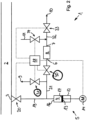
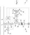
- the sampling device designated overall as 1, is used to remove beverage samples from a beverage line 2 in a beverage production plant.
- a pressurized gaseous beverage is arranged in the beverage line 2, for example beer or a carbonated lemonade.
- the sampling device 1 has an in Fig. 1 Connection 3, shown only schematically, which is firmly connected to the beverage line 2.
- the connection 3 is connected via a line system which has adjustable valves by means of actuators not shown in the drawing, with a pump chamber 4 of a pump 5, a particle filter 8 having an inlet 6 and an outlet 7 for filtering the beverage sample, an outlet opening 9 for waste, a delivery opening 10 for the beverage sample and a feed line 11 for a backwash medium.
- An analysis device not shown in the drawing, which is used to examine the beverage sample, such as the QFOOD QUANTOS® , can be connected to the delivery opening 10.
- the pump 5 is designed as a syringe pump which has a piston 13 which is axially displaceable in a cylinder 12 and which can be adjusted by means of a drive 14 which is only shown schematically in the drawing.
- the cylinder 12 and the piston 13 delimit a pump chamber 4, which is delimited at its upper end by an upper wall 16, at its lower end by a lower wall 17 formed by the piston 13 and laterally by the inner wall of the cylinder 12, which Pump room 4 delimited.
- the piston 13 can be moved toward and away from the upper wall 16 by means of the drive 14.
- connection 3 for the beverage line 2 is connected to the upper end of the pump chamber 4 via a first line 19. It can be clearly seen that the first line 19 opens into the pump chamber 4 on the upper wall 16.
- a first shut-off valve 20 is arranged close to the connection 3, by means of which the first line 19 can be shut off from the beverage line 2.
- the first line 19 has a first branching point, at which the first line 19 is connected via a second line 21 to a first fluid connection 22 of a first three-way valve 23.
- a second fluid connection 24 of the first three-way valve 23 is connected to the outlet opening 9 for the waste and a third fluid connection 25 of the first three-way valve 23 is connected to the inlet 6 of the particle filter 8.
- the outlet 7 of the particle filter 8 is connected to a first fluid connection 26 of a second three-way valve 27, a second fluid connection 28 of the second three-way valve 27 is connected to the delivery opening 10 for the beverage sample and a third connection 29 of the second three-way valve 27 is connected to the supply line 11 for the backwash medium tied together.
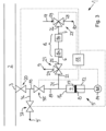
- the sampling device 1 has a second and a third shut-off valve 30, 31 instead of the first three-way valve.
- the second shut-off valve 30 is arranged between the first line 19 and the particle filter 8 in the second line 21.
- the second line 21 has a connection point between the first line 19 and the second shut-off valve 30, which is connected to the outlet opening 9 for the waste via the third shut-off valve 31.
- the outlet 7 of the particle filter 8 is connected to the delivery opening 10 for the beverage sample via a third line 32, in which a fourth shut-off valve 33 is arranged.
- a second branching point is arranged between the outlet 7 of the particle filter 8 and the fourth shut-off valve 33, at which the third line 32 is connected to the supply line 11 for the backwashing medium via a fifth shut-off valve 34.
- the control device 18 is in control connection with the shut-off valves 20, 30, 33, 34 and the drive 14 of the pump 5 in such a way that the above-mentioned steps i) to vi) are carried out.
- the second exemplary embodiment essentially corresponds to the exemplary embodiment Fig. 1 .
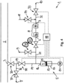
- the third exemplary embodiment shown essentially corresponds to the first exemplary embodiment, but additionally has a sixth and a seventh shut-off valve 35, 37.
- the sixth shut-off valve 35 is arranged in the first line 19 between the first shut-off valve 20 and the first branch point at which the second line 21 branches off from the first line 19.
- a third branch point is arranged between the first shut-off valve 20 and the sixth shut-off valve 35, at which the first line 19 is connected to a further outlet opening 9 'for waste via a fourth line 36, in which a seventh shut-off valve 37 is arranged.
- the first, sixth and seventh shut-off valves 20, 35, 37 are configured in such a way that the first and seventh shut-off valves 20, 37 are opened and the sixth shut-off valve 35 is closed.
- the first and sixth shut-off valves 20, 35 are open and the seventh shut-off valve 37 is closed.
- the sampling device 1 has the second and third shut-off valves 30, 31 instead of the first three-way valve 23.
- the second shut-off valve 30 is arranged between the first branch point and the particle filter 8 in the second line 21.
- the second line 21 has a connection point between the first line 19 and the second shut-off valve 30, which is connected to the outlet opening 9 for the waste via the third shut-off valve 31.
- the outlet 7 of the particle filter 8 is connected to the delivery opening 10 for the beverage sample via the third line 32, in which the fourth shut-off valve 33 is arranged. Between the outlet 7 of the particle filter 8 and the fourth shut-off valve 33, the second branching point is arranged, at which the third line 32 is connected to the feed line 11 for the backwashing medium via the fifth shut-off valve 34.
- the particle filter 8 has a pre-filter 8a and a fine filter 8b, which is arranged behind the pre-filter 8a in the flow direction of the beverage sample.
- the fine filter 8b has a smaller average pore diameter than the pre-filter 8a.
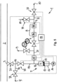
- the fourth exemplary embodiment essentially corresponds to the exemplary embodiment Fig. 3 .
- a sensor 15 for detecting the drink which is connected to the control device 18 and is designed as a pH value sensor, is arranged in the second line 21 between the first line 19 and the third shut-off valve.
- the measurement signal from the sensor 15 is compared in the control device 18 with a reference range in which the measurement signal lies when the sensor 15 is in contact with the beverage sample. If the sensor 15 is in contact with the gas emerging from the beverage sample and/or with the cleaning, disinfection and/or rinsing liquid, the measurement signal of the sensor 15 deviates from the reference range. In this case, the second shut-off valve 30 is locked in the closed position. This prevents gas, cleaning, disinfection and/or rinsing liquid from entering the particle filter 8. Otherwise, the fifth exemplary embodiment corresponds to the exemplary embodiment Fig. 4 .
- the management system of the in Fig. 6 corresponds to that in Fig. 3 , but without the first three-way valve 23, ie the first line 19 is in Fig. 6 connected directly to the inlet 6 of the particle filter 8.
- the first and sixth shut-off valves 20, 35 are opened and the seventh shut-off valve 37 is closed to introduce the beverage sample into the pump room 4.
- the pump chamber 4 is separated from the delivery opening 10 for the beverage sample and the supply line 11 for the backwashing medium by the second three-way valve 27.
- the sixth shut-off valve 35 is closed to degas the beverage sample located in the pump room 4 and the pump room 4 is further separated from the delivery opening 10 and the supply line 11 by the second three-way valve 27.
- the first shut-off valve 20 is closed and the sixth and seventh shut-off valves 35, 37 are opened so that the gas can be drained from the pump chamber 4 to the waste outlet opening 9 arranged behind the seventh shut-off valve 37.
- the pump chamber 4 is further separated from the delivery opening 10 and the supply line 11 via the second three-way valve 27.
- the first shut-off valve 20 is closed and the pump chamber 4 is connected to the discharge opening 10 via the pre-filter 8a, the fine filter 8b and the second three-way valve 27.
- the supply line 11 for the backwashing medium is connected to the outlet 7 of the fine filter 8b via the second three-way valve 27 and the inlet of the pre-filter 8a is connected to the outlet 9 for the waste via the sixth and seventh shut-off valves 35, 37.
- the delivery opening 10 is through second Three-way valve 27 separated from the supply line 11 and the outlet 7 of the fine filter 8b.
- the first shut-off valve 20 is closed.
Landscapes
- Life Sciences & Earth Sciences (AREA)
- Health & Medical Sciences (AREA)
- Chemical & Material Sciences (AREA)
- General Physics & Mathematics (AREA)
- Pathology (AREA)
- Analytical Chemistry (AREA)
- Biochemistry (AREA)
- General Health & Medical Sciences (AREA)
- Physics & Mathematics (AREA)
- Immunology (AREA)
- Hydrology & Water Resources (AREA)
- Engineering & Computer Science (AREA)
- Food Science & Technology (AREA)
- Medicinal Chemistry (AREA)
- Biomedical Technology (AREA)
- Molecular Biology (AREA)
- Sampling And Sample Adjustment (AREA)
Claims (11)
- Dispositif d'échantillonnage (1) permettant le prélèvement d'échantillons de boisson d'une conduite de boisson (2), laquelle contient une boisson gazeuse pressurisée, le dispositif d'échantillonnage (1) ayant- un raccordement (3) pour la conduite de boisson (2),- une pompe (5) présentant un entraînement (14), laquelle pompe a une chambre de pompe (4) qui est délimitée par des parois (16, 17) qui peuvent être rapprochées et éloignées l'une de l'autre au moyen de l'entraînement (14) pour l'expansion et la compression de la chambre de pompe (4),- une ouverture de distribution (10) pour l'échantillon de boisson,- un filtre à particules (8) doté d'une entrée et d'une sortie pour l'échantillon de boisson, pour la filtration de l'échantillon de boisson,- un système de conduites présentant des soupapes réglables, lequel est relié au raccordement (3) pour la conduite de boisson (2), à la chambre de pompe (4), à l'ouverture de distribution (10), à l'entrée (6) du filtre à particules (8), à la sortie (7) du filtre à particules (8), à une conduite d'amenée (11) pour un milieu de lavage à contrecourant et à une ouverture de sortie (9) pour des déchets, et- un dispositif de commande (18),et le système de conduites étant configuré de telle sorte et le dispositif de commande (18) étant en liaison de commande avec la pompe (5) et les soupapes de telle sortei) que dans une première configuration de soupapes, dans laquelle la chambre de pompe (4) est reliée au raccordement (3) pour la conduite de boisson (2) et est séparée de l'ouverture de sortie (9), de la conduite d'amenée (11) pour le milieu de lavage à contrecourant ainsi que de l'ouverture de distribution (10), un échantillon de boisson, dont le volume est inférieur au volume maximal de la chambre de pompe (4), peut être introduit à partir du raccordement (3) pour la conduite de boisson (2) dans la chambre de pompe (4),ii) qu'ensuite une deuxième configuration de soupapes est réglée, dans laquelle la chambre de pompe (4) est séparée du raccordement (3) pour la conduite de boisson (2), de l'ouverture de sortie (9), de la conduite d'amenée (11) pour le milieu de lavage à contrecourant ainsi que de l'ouverture de distribution (10), et la chambre de pompe (4) est agrandie de telle sorte qu'une dépression soit produite dans la chambre de pompe pour le dégazage de l'échantillon de boisson,iii) qu'ensuite une troisième configuration de soupapes est réglée, dans laquelle la chambre de pompe (4) est reliée à l'ouverture de sortie (9) et séparée du raccordement (3) pour la conduite de boisson (2), de la conduite d'amenée (11) pour le milieu de lavage à contrecourant ainsi que de l'ouverture de distribution (10), et la chambre de pompe (4) est comprimée de telle sorte qu'un premier volume partiel se trouvant dans une partie supérieure de la chambre de pompe (4) soit refoulé vers l'ouverture de sortie (9) et qu'un deuxième volume partiel se trouvant dans une partie inférieure de la chambre de pompe (4) demeure dans la chambre de pompe (4),iv) qu'ensuite une quatrième configuration de soupapes est réglée, dans laquelle la chambre de pompe (4) est reliée à l'ouverture de distribution (10) par le biais du filtre à particules (8) et séparée du raccordement (3) pour la conduite de boisson (2), de la conduite d'amenée (11) pour le milieu de lavage à contrecourant ainsi que de l'ouverture de sortie (9), et la chambre de pompe (4) est comprimée davantage pour refouler l'échantillon de boisson qui s'y trouve vers l'ouverture de distribution (10), et(v) qu'ensuite pour le lavage à contrecourant du filtre à particules (8) une cinquième configuration de soupapes est réglée, dans laquelle la conduite d'amenée (11) pour le milieu de lavage à contrecourant est reliée à l'ouverture de sortie (9) par le biais du filtre à particules (8).
- Dispositif d'échantillonnage (1) selon la revendication 1, caractérisé en ce que le dispositif de commande (18) est configuré de telle sorte que les étapes ii) et iii) de la revendication 1 sont répétées au moins une fois, avant que l'étape iv) de la revendication 1 ne soit effectuée.
- Dispositif d'échantillonnage (1) selon la revendication 1 ou 2, caractérisé en ce que, dans la deuxième et/ou la troisième configuration de soupapes, la chambre de pompe (4) est séparée de l'entrée (6) du filtre à particules (8).
- Dispositif d'échantillonnage (1) selon l'une des revendications 1 à 3, caractérisé en ce que le filtre à particules (8) présente un préfiltre (8a) et un filtre fin (8b) monté en série avec celui-ci, et en ce que l'entrée (6) du filtre à particules (8) est disposée au niveau du préfiltre (8a) et la sortie (7) du filtre à particules (8) est disposée au niveau du filtre fin (8b).
- Dispositif d'échantillonnage (1) selon l'une des revendications 1 à 4, caractérisé en ce que le raccordement (3) pour la conduite de boisson (2) est relié à la chambre de pompe (4) par le biais d'une première conduite (19), en ce qu'une première soupape d'arrêt (20) est disposée dans la première conduite (19), en ce que la chambre de pompe (4) est reliée à un premier raccordement de fluide (22) d'une première soupape à trois voies (23) par le biais d'une deuxième conduite (21) qui débouche dans la chambre de pompe (4) ou est raccordée à la première conduite (19) au niveau d'un premier point de bifurcation disposé entre cette chambre de pompe et la première soupape d'arrêt (20), en ce qu'un deuxième raccordement de fluide (24) de la première soupape à trois voies (23) est relié à l'ouverture de sortie (10) et un troisième raccordement de fluide (25) de la première soupape à trois voies (23) est relié à l'entrée (6) du filtre à particules (8).
- Dispositif d'échantillonnage (1) selon l'une des revendications 1 à 4, caractérisé en ce que le raccordement (3) pour la conduite de boisson (2) est relié à la chambre de pompe (4) par le biais d'une première conduite (19), en ce qu'une première soupape d'arrêt (20) est disposée dans la première conduite (19), en ce que la chambre de pompe (4) est reliée à l'entrée (6) du filtre à particules (8) par le biais d'une deuxième conduite (21) qui débouche dans la chambre de pompe (4) ou est raccordée à la première conduite (19) au niveau d'un premier point de bifurcation disposé entre cette chambre de pompe et la première soupape d'arrêt (20), en ce qu'une deuxième soupape d'arrêt (30) est disposée dans la deuxième conduite (21), et un point de raccordement est prévu au niveau de la chambre de pompe (4) et/ou au niveau de la première conduite (19) entre la chambre de pompe (4) et la première soupape d'arrêt (20) et/ou au niveau de la deuxième conduite (21) entre la chambre de pompe (4) et la deuxième soupape d'arrêt (30), lequel point de raccordement est relié à l'ouverture de sortie (9) pour les déchets par le biais d'une troisième soupape d'arrêt (31).
- Dispositif d'échantillonnage (1) selon la revendication 5 ou 6, caractérisé en ce qu'au moins un capteur (15) pour la détection de la boisson relié au dispositif de commande (18) est disposé dans le système de conduites entre le raccordement (3) pour la conduite de boisson (2) et l'entrée (6) du filtre à particules (8) et/ou entre la chambre de pompe (4) et l'entrée (6) du filtre à particules (8), et en ce que le dispositif de commande (18) est configuré de telle sorte que l'entrée (6) du filtre à particules (8) est bloquée au moyen de la première soupape à trois voies (23) ou de la deuxième soupape d'arrêt (30) lorsque le capteur (15) ne détecte pas la boisson.
- Dispositif d'échantillonnage (1) selon la revendication 7, caractérisé en ce que le capteur (15) présente un capteur de conductivité et/ou un capteur de valeur pH.
- Dispositif d'échantillonnage (1) selon l'une des revendications 1 à 8, caractérisé en ce que la sortie (7) du filtre à particules (8) est reliée à un premier raccordement de fluide (26) d'une deuxième soupape à trois voies (27), en ce qu'un deuxième raccordement de fluide (28) de la deuxième soupape à trois voies (27) est relié à l'ouverture de distribution (9) pour l'échantillon de boisson et un troisième raccordement de fluide (29) de la deuxième soupape à trois voies (27) est relié à la conduite d'amenée (11) pour le milieu de lavage à contrecourant.
- Dispositif d'échantillonnage (1) selon l'une des revendications 1 à 8, caractérisé en ce que la sortie (7) du filtre à particules est reliée à l'ouverture de distribution (10) pour l'échantillon de boisson par le biais d'une troisième conduite (32) dans laquelle une quatrième soupape d'arrêt (33) est disposée, et en ce qu'un deuxième point de bifurcation est disposé entre la sortie (7) du filtre à particules (8) et la quatrième soupape d'arrêt (33), point de bifurcation au niveau duquel la troisième conduite (32) est reliée à la conduite d'amenée (11) pour le milieu de lavage à contrecourant par le biais d'une cinquième soupape d'arrêt (34).
- Dispositif d'échantillonnage (1) selon l'une des revendications 1 à 10, caractérisé en ce que le raccordement (3) pour la conduite de boisson (2) est relié à la chambre de pompe (4) par le biais d'une première conduite (19), en ce que, dans la première conduite (19), la première soupape d'arrêt (20) et une sixième soupape d'arrêt (35) sont montées en série, en ce que la chambre de pompe (4) ou un premier point de bifurcation prévu entre la sixième soupape d'arrêt (35) et la chambre de pompe (4) dans la première conduite (19) est relié à l'entrée (6) du filtre à particules (8) par le biais de la deuxième conduite (21), et en ce qu'un troisième point de bifurcation est disposé entre la première soupape d'arrêt (20) et la sixième soupape d'arrêt (35), point de bifurcation au niveau duquel la première conduite (19) est reliée à l'ouverture de sortie (9) ou à une autre ouverture de sortie (9') pour les déchets par le biais d'une quatrième conduite (36) dans laquelle une septième soupape d'arrêt (37) est disposée.
Applications Claiming Priority (2)
| Application Number | Priority Date | Filing Date | Title |
|---|---|---|---|
| DE102016007094.3A DE102016007094B3 (de) | 2016-06-10 | 2016-06-10 | Probenentnahmevorrichtung zur Entnahme von Getränkeproben aus einer Getränkeleitung, die ein unter Druck stehendes gashaltiges Getränk enthält |
| PCT/EP2017/064011 WO2017211980A1 (fr) | 2016-06-10 | 2017-06-08 | Dispositif d'échantillonnage permettant le prélèvement d'échantillons de boisson d'une conduite de boisson, laquelle contient une boisson gazeuse pressurisée |
Publications (3)
| Publication Number | Publication Date |
|---|---|
| EP3469331A1 EP3469331A1 (fr) | 2019-04-17 |
| EP3469331C0 EP3469331C0 (fr) | 2023-10-18 |
| EP3469331B1 true EP3469331B1 (fr) | 2023-10-18 |
Family
ID=57466918
Family Applications (1)
| Application Number | Title | Priority Date | Filing Date |
|---|---|---|---|
| EP17729105.1A Active EP3469331B1 (fr) | 2016-06-10 | 2017-06-08 | Dispositif d'échantillonnage permettant le prélèvement d'échantillons de boisson d'une conduite de boisson, laquelle contient une boisson gazeuse pressurisée |
Country Status (4)
| Country | Link |
|---|---|
| US (1) | US10989631B2 (fr) |
| EP (1) | EP3469331B1 (fr) |
| DE (1) | DE102016007094B3 (fr) |
| WO (1) | WO2017211980A1 (fr) |
Families Citing this family (1)
| Publication number | Priority date | Publication date | Assignee | Title |
|---|---|---|---|---|
| AU2021372900A1 (en) * | 2020-11-02 | 2023-06-08 | Foss Analytical A/S | Method of and analyser for the optical analysis of a liquid containing a dissolved gas |
Citations (1)
| Publication number | Priority date | Publication date | Assignee | Title |
|---|---|---|---|---|
| US20130319087A1 (en) * | 2012-05-30 | 2013-12-05 | Arkray, Inc. | Bubble reduction device, chromatography device, bubble reduction method, and bubble reduction program |
Family Cites Families (62)
| Publication number | Priority date | Publication date | Assignee | Title |
|---|---|---|---|---|
| US3673853A (en) * | 1970-05-11 | 1972-07-04 | Sybron Corp | Gas content of liquid determination |
| US3789670A (en) * | 1972-08-02 | 1974-02-05 | Cities Service Oil Co | Cell for collecting and mixing fluids |
| DE2441844A1 (de) * | 1974-08-31 | 1976-03-11 | Dornier System Gmbh | Vorrichtung zur entnahme von fluessigkeitsproben |
| US3942356A (en) * | 1974-09-30 | 1976-03-09 | E. & J. Gallo Winery | On-line carbon dioxide analyzer and analyzing method |
| DE2451043C2 (de) * | 1974-10-26 | 1985-06-20 | W.Dockhorn ECS-Meßtechnik, 4460 Nordhorn | Vorrichtung zur Entnahme einer Flüssigkeitsprobe und zur Trennung der darin enthaltenen Bestandteile, insbesondere zur Entgasung der jeweils entnommenen Probe |
| DE2514413A1 (de) * | 1975-04-02 | 1976-10-21 | Holste | Vorrichtung zur probenahme aus druckleitungen |
| GB1501903A (en) * | 1975-04-18 | 1978-02-22 | British Petroleum Co | Sampling device |
| US4013413A (en) * | 1975-07-10 | 1977-03-22 | The United States Of America As Represented By The Secretary Of Agriculture | Apparatus and method for rapid analyses of plurality of samples |
| US4204962A (en) * | 1978-03-03 | 1980-05-27 | Phillips Petroleum Company | Continuous analysis of beverages |
| US4257259A (en) * | 1978-03-03 | 1981-03-24 | Phillips Petroleum Company | Continuous analysis of beverages |
| US4307620A (en) * | 1978-03-04 | 1981-12-29 | Jiskoot Joost J | Liquid sampling system |
| LU82145A1 (fr) * | 1980-02-07 | 1981-09-10 | Cipari | Perfectionnements aux procedes et installations utilisant des levures |
| US4470316A (en) * | 1980-10-21 | 1984-09-11 | Jiskoot Jakob J | Apparatus and method for withdrawing fluid from a source of fluid such as a pipeline |
| US4527436A (en) * | 1983-12-06 | 1985-07-09 | Jones Richard W | Apparatus and method for sampling a liquid |
| US4763514A (en) * | 1986-05-14 | 1988-08-16 | Mitsubishi Denki Kabushiki Kaisha | Monitoring equipment for dissolved gas in insulating oil |
| US4745794A (en) * | 1986-12-22 | 1988-05-24 | E. I. Du Pont De Nemours And Company | Analyzer for carbon dioxide in beverages |
| US4987083A (en) * | 1986-12-29 | 1991-01-22 | Apple Glenn D | Photometric analyzer and controller for beverages |
| NL8700256A (nl) * | 1987-02-03 | 1988-09-01 | Veg Gasinstituut Nv | Werkwijze voor het bemonsteren van een fluidumstroom alsmede daarvoor geschikte inrichting. |
| CA1299892C (fr) * | 1987-05-14 | 1992-05-05 | Walter T. Hogg | Variante de chromatographie en phase gazeuse |
| US5116330A (en) * | 1987-05-29 | 1992-05-26 | Spencer R Wilson | Sample extraction system |
| US4955992A (en) * | 1987-06-26 | 1990-09-11 | Beckman Instruments, Inc. | Liquid degassing system |
| US5131226A (en) * | 1987-07-09 | 1992-07-21 | Milad Limited Partnership | Variable volume reservoir and method for its use |
| CA1299893C (fr) * | 1987-09-17 | 1992-05-05 | Molson Companies Limited, (The) | Robinet d'echantillonnage liquide pour chromatographe en phase gazeuse |
| CA1332293C (fr) * | 1988-09-01 | 1994-10-11 | Gunilla K. E. Seifert | Appareil d'echantillonnage automatique, aseptique |
| EP0367899A1 (fr) | 1988-11-05 | 1990-05-16 | SCHWARTE-WERK GmbH | Méthode et appareil d'extraction d'échantillons liquides d'une tuyère de passage de liquide |
| DE3920949A1 (de) * | 1989-06-27 | 1991-01-10 | Sartorius Gmbh | An eine prozess- oder abfuelleitung anschliessbares probenentnahmegeraet fuer fluessigkeiten |
| US5068116A (en) * | 1989-10-04 | 1991-11-26 | Micro-Blend, Inc. | Method for beverage blending and proportioning |
| US5213982A (en) * | 1990-11-23 | 1993-05-25 | Phillips Petroleum Company | Heated dilution method for a liquid sample |
| US5183486A (en) * | 1990-12-04 | 1993-02-02 | Spectra-Physics, Inc. | Apparatus for degassing a liquid |
| US5192984A (en) * | 1990-12-19 | 1993-03-09 | Environmental Analytical Systems, Inc. | Apparatus and method for determination of concentrations |
| US5220513A (en) * | 1991-02-19 | 1993-06-15 | Seiden Louis W | Gas content measurement in a sealed container of liquid by degassing |
| GB2265138A (en) * | 1992-03-21 | 1993-09-22 | Pius Thomas Merton | Liquid dispenser |
| US5433120A (en) * | 1993-07-30 | 1995-07-18 | Texas Sampling, Inc. | Sampling system for septum closed container |
| US5361643A (en) * | 1993-07-30 | 1994-11-08 | Texas Sampling Co. | LPG sampling system |
| NO178357C (no) * | 1993-10-12 | 1996-03-06 | Statoil As | Apparatur for bruk ved testing av en skjærkraftpåvirkbar tetningsvæske |
| US5736654A (en) * | 1995-11-22 | 1998-04-07 | The Dow Chemical Company | Self-contained on-line sampling apparatus |
| US5925833A (en) * | 1997-03-24 | 1999-07-20 | Peterson; Roger | Process plant sample collection system and method |
| EP1035407A2 (fr) | 1999-03-05 | 2000-09-13 | Jansky Gmbh | Dispositif de prise d'échantillons dans un appareil collecteur de lait |
| DE10061725B4 (de) * | 2000-12-12 | 2009-05-14 | Schöpf, Alfred | Vorrichtung zur Entnahme von Proben |
| EP1308713A1 (fr) * | 2001-11-02 | 2003-05-07 | Qmet ApS | Procédé de détermination de la teneur de SO2 dans un produit de boisson |
| US7951597B2 (en) * | 2002-09-11 | 2011-05-31 | Waters Technologies Corporation | Pressurized fluid sample injector and method of injecting fluid samples |
| DK175416B1 (da) | 2002-10-09 | 2004-10-04 | Niels Flemming Greve Hansen | Fremgangsmåde og apparat til udtagning og bestemmelse af karakteristika ved en væskepröve |
| US7169599B2 (en) * | 2003-06-20 | 2007-01-30 | Groton Biosystems, Llc | Fluid interface for bioprocessor systems |
| DE10352924A1 (de) | 2003-11-11 | 2005-07-14 | Johann Wolfgang Goethe-Universität Frankfurt am Main | Vorrichtung und Verfahren zur qualitativen und/oder quantitativen Analyse von Inhaltsstoffen in Flüssigkeiten, insbesondere in Getränke- und Prozessflüssigkeiten |
| DE102004004342A1 (de) * | 2004-01-29 | 2005-08-18 | Hydac Filtertechnik Gmbh | Vorrichtung zur Prüfung mindestens eines Qualitätsparameters eines Fluids |
| US8092744B1 (en) * | 2008-02-27 | 2012-01-10 | EST Analytical, Inc. | Analytical chemical sampling system with bypass mode |
| US8549934B2 (en) * | 2008-03-25 | 2013-10-08 | Flownamics Analytical Instruments, Inc. | Segmented online sampling apparatus and method of use |
| CA2764047C (fr) * | 2009-06-03 | 2016-12-13 | Agilent Technologies, Inc. | Injecteur d'echantillon pourvu d'un dispositif doseur pour equilibrer les differences de pression dans un etat de valve intermediaire |
| FR2959315B1 (fr) * | 2010-04-22 | 2012-04-27 | Gdf Suez | Installation et procede de caracterisation de gaz dissous dans un liquide |
| US10107728B2 (en) * | 2011-02-11 | 2018-10-23 | Schlumberger Technology Corporation | Microfluidic system and method for performing a flash separation of a reservoir fluid sample |
| BR112013028545A2 (pt) * | 2011-05-06 | 2016-09-20 | Bend Res Inc | válvula de amostragem asséptica automática para amostragem de recipientes fechados |
| WO2013063128A1 (fr) * | 2011-10-24 | 2013-05-02 | Bend Research, Inc. | Systèmes et procédés de production de bioproduits |
| US9389151B2 (en) * | 2012-11-05 | 2016-07-12 | Bend Research, Inc. | Fixed volume aseptic sampling valve for sampling from enclosed containers |
| WO2015052134A1 (fr) * | 2013-10-08 | 2015-04-16 | Sartorius Stedim Biotech Gmbh | Dispositif de prélèvement et procédé pour obtenir un échantillon d'un milieu à prélever |
| US9334728B2 (en) * | 2014-01-16 | 2016-05-10 | Dwt Solutions, L.P. | Oil well production analyzing system |
| EP2950076B1 (fr) * | 2014-05-26 | 2017-06-28 | CSEM Centre Suisse d'Electronique et de Microtechnique SA - Recherche et Développement | Système portable de préparation automatisée d'échantillons liquides et/ou solides |
| DE102014110544B3 (de) * | 2014-07-25 | 2015-09-24 | Leibniz-Institut Für Analytische Wissenschaften - Isas - E.V. | Vorrichtung zur Entnahme einer Probe und zur Zuführung in ein analytisches Auswertesystem |
| DE202014106092U1 (de) | 2014-12-17 | 2016-03-18 | Hlw Gmbh | Milchsammelvorrichtung |
| US9846109B2 (en) * | 2015-10-27 | 2017-12-19 | Sgs North America Inc. | Fluid sampling |
| EP3165596B1 (fr) * | 2015-11-05 | 2019-07-24 | Simon H. Steiner, Hopfen, GmbH | Procede de nettoyage de biere et nettoyeur de biere |
| MX2019001067A (es) * | 2016-07-25 | 2019-11-21 | Bevcorp Llc | Sistema y metodo para retirar el aire de bebidas. |
| US10481049B2 (en) * | 2017-11-28 | 2019-11-19 | Air Liquide Canada, Inc. | Cryogenic liquid sampler |
-
2016
- 2016-06-10 DE DE102016007094.3A patent/DE102016007094B3/de active Active
-
2017
- 2017-06-08 EP EP17729105.1A patent/EP3469331B1/fr active Active
- 2017-06-08 WO PCT/EP2017/064011 patent/WO2017211980A1/fr not_active Ceased
- 2017-06-08 US US16/308,174 patent/US10989631B2/en active Active
Patent Citations (1)
| Publication number | Priority date | Publication date | Assignee | Title |
|---|---|---|---|---|
| US20130319087A1 (en) * | 2012-05-30 | 2013-12-05 | Arkray, Inc. | Bubble reduction device, chromatography device, bubble reduction method, and bubble reduction program |
Also Published As
| Publication number | Publication date |
|---|---|
| EP3469331C0 (fr) | 2023-10-18 |
| US10989631B2 (en) | 2021-04-27 |
| EP3469331A1 (fr) | 2019-04-17 |
| US20190301981A1 (en) | 2019-10-03 |
| DE102016007094B3 (de) | 2016-12-22 |
| WO2017211980A1 (fr) | 2017-12-14 |
Similar Documents
| Publication | Publication Date | Title |
|---|---|---|
| DE69719818T2 (de) | Flüssigkeitstransportsystem | |
| DE68907918T2 (de) | Vorrichtung zum parallelfiltrieren einer mehrzahl von proben, automatische kontrolle des filtratvolumens und der verschmutzung, filterindexation und verfahren zum filtrieren. | |
| DE69104367T2 (de) | Ausgabeverfahren und -vorrichtung, insbesondere für dichtungs-/klebemittel. | |
| EP3810747B1 (fr) | Système de traitement modulaire et procédé de montage modulaire d'un système de traitement | |
| DE1128185B (de) | Vorrichtung zur Entnahme von Proben aus Fluessigkeiten | |
| EP1045238A2 (fr) | Soupape et appareil pour l'extraction des échantillons liquides d'une cavité à faibles pertes | |
| DE2123375A1 (de) | Meßeinrichtung zur Bestimmung des Gasgehalts von Flüssigkeiten | |
| EP3688459B1 (fr) | Dispositif de détection de la qualité d'un liquide dans un tube d'alimentation | |
| EP3197582B1 (fr) | Dispositif de purge d'air et de vérification de l'intégrité | |
| DE69202118T2 (de) | Einrichtung zum Trennen von unter hohem Druck stehenden Flüssigkeitsproben. | |
| DE102014000056B3 (de) | Vorrichtung und Verfahren zur spektroskopischen Bestimmung von Komponenten in Flüssigkeiten | |
| DE102016007094B3 (de) | Probenentnahmevorrichtung zur Entnahme von Getränkeproben aus einer Getränkeleitung, die ein unter Druck stehendes gashaltiges Getränk enthält | |
| DE102010046988B4 (de) | Verfahren und Vorrichtung zur Überwachung einer Mehrzahl von parallel angeordneten Filtrationssystemen mittels einer Trübungsmessung | |
| EP1549421B1 (fr) | Dispositif et procédé de prélèvement d'échantillons liquides | |
| EP3624927A1 (fr) | Module de filtration à usage unique ou module de nettoyage à usage unique, pouvant être utilisés respectivement pour un système de filtration modulaire | |
| EP2078947A2 (fr) | Dispositif de mesure et procédé de mesure destinés à la mesure automatique des propriétés de la boue de curages présentes dans une installation de biogaz | |
| WO1992006363A1 (fr) | Procede et dispositif pour l'extraction et la manutention d'echantillons | |
| DE102015115620B4 (de) | Entgasungsmodul | |
| WO2002103324A2 (fr) | Procede et dispositif de prelevement d'un echantillon dans une charge fluidique | |
| DE102012217855A1 (de) | Mehrlumige Injektornadel für unterschiedlich skalierte Probenmesseinrichtungen | |
| EP1279951A2 (fr) | Dispositif pour le traitement d'une sonde de mesure et leurs utilisations | |
| DE2613212C2 (de) | Verfahren zur Bestimmung des Fließverhaltens von Flüssigkeiten für medizinische und pharmazeutische Zwecke, sowie Vorrichtung zur Durchführung des Verfahrens | |
| CH675303A5 (fr) | ||
| WO2004038281A1 (fr) | Procede et dispositif de prelevement d'echantillons liquides contenus dans des recipients sous pression | |
| EP3106178A1 (fr) | Boitier de filtre a bougie |
Legal Events
| Date | Code | Title | Description |
|---|---|---|---|
| STAA | Information on the status of an ep patent application or granted ep patent |
Free format text: STATUS: UNKNOWN |
|
| STAA | Information on the status of an ep patent application or granted ep patent |
Free format text: STATUS: THE INTERNATIONAL PUBLICATION HAS BEEN MADE |
|
| PUAI | Public reference made under article 153(3) epc to a published international application that has entered the european phase |
Free format text: ORIGINAL CODE: 0009012 |
|
| STAA | Information on the status of an ep patent application or granted ep patent |
Free format text: STATUS: REQUEST FOR EXAMINATION WAS MADE |
|
| 17P | Request for examination filed |
Effective date: 20190110 |
|
| AK | Designated contracting states |
Kind code of ref document: A1 Designated state(s): AL AT BE BG CH CY CZ DE DK EE ES FI FR GB GR HR HU IE IS IT LI LT LU LV MC MK MT NL NO PL PT RO RS SE SI SK SM TR |
|
| AX | Request for extension of the european patent |
Extension state: BA ME |
|
| DAV | Request for validation of the european patent (deleted) | ||
| DAX | Request for extension of the european patent (deleted) | ||
| STAA | Information on the status of an ep patent application or granted ep patent |
Free format text: STATUS: EXAMINATION IS IN PROGRESS |
|
| 17Q | First examination report despatched |
Effective date: 20210913 |
|
| GRAP | Despatch of communication of intention to grant a patent |
Free format text: ORIGINAL CODE: EPIDOSNIGR1 |
|
| STAA | Information on the status of an ep patent application or granted ep patent |
Free format text: STATUS: GRANT OF PATENT IS INTENDED |
|
| INTG | Intention to grant announced |
Effective date: 20230321 |
|
| GRAJ | Information related to disapproval of communication of intention to grant by the applicant or resumption of examination proceedings by the epo deleted |
Free format text: ORIGINAL CODE: EPIDOSDIGR1 |
|
| GRAP | Despatch of communication of intention to grant a patent |
Free format text: ORIGINAL CODE: EPIDOSNIGR1 |
|
| INTG | Intention to grant announced |
Effective date: 20230601 |
|
| GRAS | Grant fee paid |
Free format text: ORIGINAL CODE: EPIDOSNIGR3 |
|
| GRAA | (expected) grant |
Free format text: ORIGINAL CODE: 0009210 |
|
| STAA | Information on the status of an ep patent application or granted ep patent |
Free format text: STATUS: THE PATENT HAS BEEN GRANTED |
|
| AK | Designated contracting states |
Kind code of ref document: B1 Designated state(s): AL AT BE BG CH CY CZ DE DK EE ES FI FR GB GR HR HU IE IS IT LI LT LU LV MC MK MT NL NO PL PT RO RS SE SI SK SM TR |
|
| REG | Reference to a national code |
Ref country code: GB Ref legal event code: FG4D Free format text: NOT ENGLISH |
|
| REG | Reference to a national code |
Ref country code: CH Ref legal event code: EP |
|
| REG | Reference to a national code |
Ref country code: IE Ref legal event code: FG4D Free format text: LANGUAGE OF EP DOCUMENT: GERMAN |
|
| REG | Reference to a national code |
Ref country code: DE Ref legal event code: R096 Ref document number: 502017015507 Country of ref document: DE |
|
| U01 | Request for unitary effect filed |
Effective date: 20231019 |
|
| U07 | Unitary effect registered |
Designated state(s): AT BE BG DE DK EE FI FR IT LT LU LV MT NL PT SE SI Effective date: 20231025 |
|
| PG25 | Lapsed in a contracting state [announced via postgrant information from national office to epo] |
Ref country code: GR Free format text: LAPSE BECAUSE OF FAILURE TO SUBMIT A TRANSLATION OF THE DESCRIPTION OR TO PAY THE FEE WITHIN THE PRESCRIBED TIME-LIMIT Effective date: 20240119 |
|
| PG25 | Lapsed in a contracting state [announced via postgrant information from national office to epo] |
Ref country code: IS Free format text: LAPSE BECAUSE OF FAILURE TO SUBMIT A TRANSLATION OF THE DESCRIPTION OR TO PAY THE FEE WITHIN THE PRESCRIBED TIME-LIMIT Effective date: 20240218 |
|
| PG25 | Lapsed in a contracting state [announced via postgrant information from national office to epo] |
Ref country code: ES Free format text: LAPSE BECAUSE OF FAILURE TO SUBMIT A TRANSLATION OF THE DESCRIPTION OR TO PAY THE FEE WITHIN THE PRESCRIBED TIME-LIMIT Effective date: 20231018 |
|
| PG25 | Lapsed in a contracting state [announced via postgrant information from national office to epo] |
Ref country code: IS Free format text: LAPSE BECAUSE OF FAILURE TO SUBMIT A TRANSLATION OF THE DESCRIPTION OR TO PAY THE FEE WITHIN THE PRESCRIBED TIME-LIMIT Effective date: 20240218 Ref country code: GR Free format text: LAPSE BECAUSE OF FAILURE TO SUBMIT A TRANSLATION OF THE DESCRIPTION OR TO PAY THE FEE WITHIN THE PRESCRIBED TIME-LIMIT Effective date: 20240119 Ref country code: ES Free format text: LAPSE BECAUSE OF FAILURE TO SUBMIT A TRANSLATION OF THE DESCRIPTION OR TO PAY THE FEE WITHIN THE PRESCRIBED TIME-LIMIT Effective date: 20231018 |
|
| PG25 | Lapsed in a contracting state [announced via postgrant information from national office to epo] |
Ref country code: RS Free format text: LAPSE BECAUSE OF FAILURE TO SUBMIT A TRANSLATION OF THE DESCRIPTION OR TO PAY THE FEE WITHIN THE PRESCRIBED TIME-LIMIT Effective date: 20231018 Ref country code: PL Free format text: LAPSE BECAUSE OF FAILURE TO SUBMIT A TRANSLATION OF THE DESCRIPTION OR TO PAY THE FEE WITHIN THE PRESCRIBED TIME-LIMIT Effective date: 20231018 Ref country code: NO Free format text: LAPSE BECAUSE OF FAILURE TO SUBMIT A TRANSLATION OF THE DESCRIPTION OR TO PAY THE FEE WITHIN THE PRESCRIBED TIME-LIMIT Effective date: 20240118 Ref country code: HR Free format text: LAPSE BECAUSE OF FAILURE TO SUBMIT A TRANSLATION OF THE DESCRIPTION OR TO PAY THE FEE WITHIN THE PRESCRIBED TIME-LIMIT Effective date: 20231018 |
|
| REG | Reference to a national code |
Ref country code: DE Ref legal event code: R097 Ref document number: 502017015507 Country of ref document: DE |
|
| PG25 | Lapsed in a contracting state [announced via postgrant information from national office to epo] |
Ref country code: CZ Free format text: LAPSE BECAUSE OF FAILURE TO SUBMIT A TRANSLATION OF THE DESCRIPTION OR TO PAY THE FEE WITHIN THE PRESCRIBED TIME-LIMIT Effective date: 20231018 |
|
| U20 | Renewal fee for the european patent with unitary effect paid |
Year of fee payment: 8 Effective date: 20240620 |
|
| PG25 | Lapsed in a contracting state [announced via postgrant information from national office to epo] |
Ref country code: SK Free format text: LAPSE BECAUSE OF FAILURE TO SUBMIT A TRANSLATION OF THE DESCRIPTION OR TO PAY THE FEE WITHIN THE PRESCRIBED TIME-LIMIT Effective date: 20231018 |
|
| PG25 | Lapsed in a contracting state [announced via postgrant information from national office to epo] |
Ref country code: SM Free format text: LAPSE BECAUSE OF FAILURE TO SUBMIT A TRANSLATION OF THE DESCRIPTION OR TO PAY THE FEE WITHIN THE PRESCRIBED TIME-LIMIT Effective date: 20231018 Ref country code: SK Free format text: LAPSE BECAUSE OF FAILURE TO SUBMIT A TRANSLATION OF THE DESCRIPTION OR TO PAY THE FEE WITHIN THE PRESCRIBED TIME-LIMIT Effective date: 20231018 Ref country code: RO Free format text: LAPSE BECAUSE OF FAILURE TO SUBMIT A TRANSLATION OF THE DESCRIPTION OR TO PAY THE FEE WITHIN THE PRESCRIBED TIME-LIMIT Effective date: 20231018 Ref country code: CZ Free format text: LAPSE BECAUSE OF FAILURE TO SUBMIT A TRANSLATION OF THE DESCRIPTION OR TO PAY THE FEE WITHIN THE PRESCRIBED TIME-LIMIT Effective date: 20231018 |
|
| PLBE | No opposition filed within time limit |
Free format text: ORIGINAL CODE: 0009261 |
|
| STAA | Information on the status of an ep patent application or granted ep patent |
Free format text: STATUS: NO OPPOSITION FILED WITHIN TIME LIMIT |
|
| 26N | No opposition filed |
Effective date: 20240719 |
|
| PG25 | Lapsed in a contracting state [announced via postgrant information from national office to epo] |
Ref country code: MC Free format text: LAPSE BECAUSE OF FAILURE TO SUBMIT A TRANSLATION OF THE DESCRIPTION OR TO PAY THE FEE WITHIN THE PRESCRIBED TIME-LIMIT Effective date: 20231018 |
|
| REG | Reference to a national code |
Ref country code: CH Ref legal event code: PL |
|
| GBPC | Gb: european patent ceased through non-payment of renewal fee |
Effective date: 20240608 |
|
| PG25 | Lapsed in a contracting state [announced via postgrant information from national office to epo] |
Ref country code: IE Free format text: LAPSE BECAUSE OF NON-PAYMENT OF DUE FEES Effective date: 20240608 |
|
| PG25 | Lapsed in a contracting state [announced via postgrant information from national office to epo] |
Ref country code: CH Free format text: LAPSE BECAUSE OF NON-PAYMENT OF DUE FEES Effective date: 20240630 |
|
| PG25 | Lapsed in a contracting state [announced via postgrant information from national office to epo] |
Ref country code: GB Free format text: LAPSE BECAUSE OF NON-PAYMENT OF DUE FEES Effective date: 20240608 |
|
| U20 | Renewal fee for the european patent with unitary effect paid |
Year of fee payment: 9 Effective date: 20250630 |
|
| PG25 | Lapsed in a contracting state [announced via postgrant information from national office to epo] |
Ref country code: CY Free format text: LAPSE BECAUSE OF FAILURE TO SUBMIT A TRANSLATION OF THE DESCRIPTION OR TO PAY THE FEE WITHIN THE PRESCRIBED TIME-LIMIT; INVALID AB INITIO Effective date: 20170608 |
|
| PG25 | Lapsed in a contracting state [announced via postgrant information from national office to epo] |
Ref country code: HU Free format text: LAPSE BECAUSE OF FAILURE TO SUBMIT A TRANSLATION OF THE DESCRIPTION OR TO PAY THE FEE WITHIN THE PRESCRIBED TIME-LIMIT; INVALID AB INITIO Effective date: 20170608 |
|
| PG25 | Lapsed in a contracting state [announced via postgrant information from national office to epo] |
Ref country code: TR Free format text: LAPSE BECAUSE OF FAILURE TO SUBMIT A TRANSLATION OF THE DESCRIPTION OR TO PAY THE FEE WITHIN THE PRESCRIBED TIME-LIMIT Effective date: 20231018 |
|
| U20 | Renewal fee for the european patent with unitary effect paid |
Year of fee payment: 10 Effective date: 20260630 |