EP3469449B1 - Scharnier mit freistoppfunktion - Google Patents
Scharnier mit freistoppfunktion Download PDFInfo
- Publication number
- EP3469449B1 EP3469449B1 EP17730639.6A EP17730639A EP3469449B1 EP 3469449 B1 EP3469449 B1 EP 3469449B1 EP 17730639 A EP17730639 A EP 17730639A EP 3469449 B1 EP3469449 B1 EP 3469449B1
- Authority
- EP
- European Patent Office
- Prior art keywords
- female
- hinge
- friction
- friction hinge
- devices
- Prior art date
- Legal status (The legal status is an assumption and is not a legal conclusion. Google has not performed a legal analysis and makes no representation as to the accuracy of the status listed.)
- Active
Links
Images












Classifications
-
- H—ELECTRICITY
- H04—ELECTRIC COMMUNICATION TECHNIQUE
- H04M—TELEPHONIC COMMUNICATION
- H04M1/00—Substation equipment, e.g. for use by subscribers
- H04M1/02—Constructional features of telephone sets
- H04M1/0202—Portable telephone sets, e.g. cordless phones, mobile phones or bar type handsets
- H04M1/0206—Portable telephones comprising a plurality of mechanically joined movable body parts, e.g. hinged housings
- H04M1/0208—Portable telephones comprising a plurality of mechanically joined movable body parts, e.g. hinged housings characterized by the relative motions of the body parts
- H04M1/0214—Foldable telephones, i.e. with body parts pivoting to an open position around an axis parallel to the plane they define in closed position
- H04M1/0216—Foldable in one direction, i.e. using a one degree of freedom hinge
- H04M1/022—The hinge comprising two parallel pivoting axes
-
- G—PHYSICS
- G06—COMPUTING OR CALCULATING; COUNTING
- G06F—ELECTRIC DIGITAL DATA PROCESSING
- G06F1/00—Details not covered by groups G06F3/00 - G06F13/00 and G06F21/00
- G06F1/16—Constructional details or arrangements
- G06F1/1613—Constructional details or arrangements for portable computers
- G06F1/1615—Constructional details or arrangements for portable computers with several enclosures having relative motions, each enclosure supporting at least one I/O or computing function
- G06F1/1616—Constructional details or arrangements for portable computers with several enclosures having relative motions, each enclosure supporting at least one I/O or computing function with folding flat displays, e.g. laptop computers or notebooks having a clamshell configuration, with body parts pivoting to an open position around an axis parallel to the plane they define in closed position
- G06F1/1618—Constructional details or arrangements for portable computers with several enclosures having relative motions, each enclosure supporting at least one I/O or computing function with folding flat displays, e.g. laptop computers or notebooks having a clamshell configuration, with body parts pivoting to an open position around an axis parallel to the plane they define in closed position the display being foldable up to the back of the other housing with a single degree of freedom, e.g. by 360° rotation over the axis defined by the rear edge of the base enclosure
-
- B—PERFORMING OPERATIONS; TRANSPORTING
- B21—MECHANICAL METAL-WORKING WITHOUT ESSENTIALLY REMOVING MATERIAL; PUNCHING METAL
- B21D—WORKING OR PROCESSING OF SHEET METAL OR METAL TUBES, RODS OR PROFILES WITHOUT ESSENTIALLY REMOVING MATERIAL; PUNCHING METAL
- B21D53/00—Making other particular articles
- B21D53/38—Making other particular articles locksmith's goods, e.g. handles
- B21D53/40—Making other particular articles locksmith's goods, e.g. handles hinges, e.g. door hinge plates
-
- B—PERFORMING OPERATIONS; TRANSPORTING
- B21—MECHANICAL METAL-WORKING WITHOUT ESSENTIALLY REMOVING MATERIAL; PUNCHING METAL
- B21K—MAKING FORGED OR PRESSED METAL PRODUCTS, e.g. HORSE-SHOES, RIVETS, BOLTS OR WHEELS
- B21K13/00—Making locksmiths' goods, e.g. handles for cases
- B21K13/02—Making locksmiths' goods, e.g. handles for cases hinges
-
- E—FIXED CONSTRUCTIONS
- E05—LOCKS; KEYS; WINDOW OR DOOR FITTINGS; SAFES
- E05D—HINGES OR SUSPENSION DEVICES FOR DOORS, WINDOWS OR WINGS
- E05D11/00—Additional features or accessories of hinges
- E05D11/08—Friction devices between relatively-movable hinge parts
- E05D11/082—Friction devices between relatively-movable hinge parts with substantially radial friction, e.g. cylindrical friction surfaces
-
- E—FIXED CONSTRUCTIONS
- E05—LOCKS; KEYS; WINDOW OR DOOR FITTINGS; SAFES
- E05D—HINGES OR SUSPENSION DEVICES FOR DOORS, WINDOWS OR WINGS
- E05D3/00—Hinges with pins
- E05D3/06—Hinges with pins with two or more pins
- E05D3/12—Hinges with pins with two or more pins with two parallel pins and one arm
-
- G—PHYSICS
- G06—COMPUTING OR CALCULATING; COUNTING
- G06F—ELECTRIC DIGITAL DATA PROCESSING
- G06F1/00—Details not covered by groups G06F3/00 - G06F13/00 and G06F21/00
- G06F1/16—Constructional details or arrangements
- G06F1/1613—Constructional details or arrangements for portable computers
- G06F1/1633—Constructional details or arrangements of portable computers not specific to the type of enclosures covered by groups G06F1/1615 - G06F1/1626
- G06F1/1637—Details related to the display arrangement, including those related to the mounting of the display in the housing
- G06F1/1641—Details related to the display arrangement, including those related to the mounting of the display in the housing the display being formed by a plurality of foldable display components
-
- G—PHYSICS
- G06—COMPUTING OR CALCULATING; COUNTING
- G06F—ELECTRIC DIGITAL DATA PROCESSING
- G06F1/00—Details not covered by groups G06F3/00 - G06F13/00 and G06F21/00
- G06F1/16—Constructional details or arrangements
- G06F1/1613—Constructional details or arrangements for portable computers
- G06F1/1633—Constructional details or arrangements of portable computers not specific to the type of enclosures covered by groups G06F1/1615 - G06F1/1626
- G06F1/1675—Miscellaneous details related to the relative movement between the different enclosures or enclosure parts
- G06F1/1681—Details related solely to hinges
-
- G—PHYSICS
- G06—COMPUTING OR CALCULATING; COUNTING
- G06F—ELECTRIC DIGITAL DATA PROCESSING
- G06F1/00—Details not covered by groups G06F3/00 - G06F13/00 and G06F21/00
- G06F1/16—Constructional details or arrangements
- G06F1/1613—Constructional details or arrangements for portable computers
- G06F1/1633—Constructional details or arrangements of portable computers not specific to the type of enclosures covered by groups G06F1/1615 - G06F1/1626
- G06F1/1675—Miscellaneous details related to the relative movement between the different enclosures or enclosure parts
- G06F1/1683—Miscellaneous details related to the relative movement between the different enclosures or enclosure parts for the transmission of signal or power between the different housings, e.g. details of wired or wireless communication, passage of cabling
-
- E—FIXED CONSTRUCTIONS
- E05—LOCKS; KEYS; WINDOW OR DOOR FITTINGS; SAFES
- E05Y—INDEXING SCHEME ASSOCIATED WITH SUBCLASSES E05D AND E05F, RELATING TO CONSTRUCTION ELEMENTS, ELECTRIC CONTROL, POWER SUPPLY, POWER SIGNAL OR TRANSMISSION, USER INTERFACES, MOUNTING OR COUPLING, DETAILS, ACCESSORIES, AUXILIARY OPERATIONS NOT OTHERWISE PROVIDED FOR, APPLICATION THEREOF
- E05Y2999/00—Subject-matter not otherwise provided for in this subclass
-
- Y—GENERAL TAGGING OF NEW TECHNOLOGICAL DEVELOPMENTS; GENERAL TAGGING OF CROSS-SECTIONAL TECHNOLOGIES SPANNING OVER SEVERAL SECTIONS OF THE IPC; TECHNICAL SUBJECTS COVERED BY FORMER USPC CROSS-REFERENCE ART COLLECTIONS [XRACs] AND DIGESTS
- Y10—TECHNICAL SUBJECTS COVERED BY FORMER USPC
- Y10T—TECHNICAL SUBJECTS COVERED BY FORMER US CLASSIFICATION
- Y10T29/00—Metal working
- Y10T29/24—Hinge making or assembling
Definitions
- Modern mobile phones and tablets have evolved over recent years to the point where they now possess a broad range of capabilities. They are not only capable of placing and receiving mobile phone calls, multimedia messaging (MMS), and sending and receiving email, but they can also access the Internet, are GPS-enabled, possess considerable processing power and large amounts of memory, and are equipped with high-resolution color liquid crystal displays capable of detecting touch input.
- multimedia messaging MMS
- today's mobile phones are general purpose computing and telecommunication devices capable of running a multitude of applications. For example, modern mobile phones can run web browsers, navigation systems, media players and gaming applications.
- the mobile phone or tablet can include an open, expanded position where both displays are flush so that the user feels like there is a single integrated display.
- both displays In a closed, condensed position, both displays are face-to-face so as to protect the displays.
- In a fully-open position, the dual displays In a fully-open position, the dual displays can sit back-to-back so the user needs to flip the device to view the opposing display.
- Hinges for such dual-display devices are problematic. Typically, the hinges can protrude from the device as it switches between positions. As devices continually become thinner, hinges need to be adapted to accommodate the thinner displays without further protrusion from the back of the device as it is opened and closed. Additionally, excess slack can make the two displays feel loosely connected. Other problems include that the displays do not open and close smoothly. Still yet another problem is the ability to stop the displays in any position as the displays are opened and closed. Torque or friction hinges are known and offer resistance to a pivoting motion. However, the friction hinges can be bulky and protrude from the device.
- EP 1 486 858 A1 describes a dual display type portable computer including a first unit having a first display module and a second unit rotatably coupled to the first unit having a second display module. At least one hinge unit couples the first unit and the second unit with each other. The hinge unit is coupled to corresponding positions of the first unit and the second unit to enable the first display module and the second display module to overlap each other or to be unfolded until they are placed in an equal plane.
- a hinge mechanism coupled to at least a dual-display device wherein the displays can rotate with respect to each other through 360 degrees.
- the displays can be face-to-face in a closed position, in a single plane in an open-book or tablet position, and back-to-back in a fully-open position.
- the hinge mechanism has at least one flexible connection member that follows a generally S-shaped path when the displays are in a tablet position.
- a second flexible connection member can be added that follows a mirrored S-shaped path. The S-shaped path of the first flexible connection member and the mirrored S-shape path of the second flexible connection member together create a cross-configuration.
- Each device can include a hinge lug that has top and bottom channels for receiving the flexible connection members. Both the first and second flexible connection members can be coupled together through a termination block. A screw can be threaded through the hinge lug and push on the termination block so as to create tension in the first and second flexible connection members. Alternatively, a spring can be used in conjunction with the termination block to create tension in the flexible connection members.
- friction hinges can be used in conjunction with the flexible connection members.
- the friction hinges can be coupled together through a gearing mechanism so that the friction hinges cooperatively combine to provide a free-stop function.
- the hinges provide numerous advantages. Foremost, the flexible connection members stay within the channels of the hinge lugs and do not extend (or extend minimally) beyond the surface of the dual-display device as it is being rotated through 360 degrees. Moreover, the flexible connection members can be easily tightened, such as by turning a screw that is exposed externally with the dual-display device in a closed position. Moreover, the friction hinge can allow the device to free stop in any position through the 360 degree rotation.
- the hinge mechanisms and the friction hinges can be positioned adjacent to one another to provide both features simultaneously.
- FIG. 1 shows an embodiment of a hinged mobile electronic device 100 comprising a first display device 110 and a second display device 120 coupled together with one or more hinges 130, 132.
- the mobile electronic device 100 can be, for example, a hand-held device, such as a smart phone, or a portable computer, such as a lap-top.
- Each device 110, 120 can include a display and each device sits end-to-end with the hinges 130, 132 coupling the ends together with sufficient tension that the devices can pivot relative to each other around the ends.
- the mobile electronic device 100 is shown in a tablet mode with the first and second display devices aligned in a plane so as to form a larger display area.
- the second display device 120 can rotate counterclockwise relative to display device 110 or can rotate clockwise, as shown by phantom line 150.
- the hinges 130, 132 allow a full 360 degrees of rotation between the first and second display devices 110, 120.
- the embodiments described herein are shown for two-display devices, but can be extended to additional display devices, such as 3 or more displays.
- the first and second display devices 110, 120 can comprise a plurality of user interface screens 160, 170, respectively.
- the screens 160, 170 can be used for user input and/or display purposes.
- the screens 160, 170 can also be replaced with a plurality of smaller screens and/or other user interface mechanisms, such as a keyboard.
- Exemplary embodiments of the hinged mobile electronic device can comprise such user interface mechanisms on any surfaces and on any combination of surfaces as desired.
- FIGS. 2A-2E show different positions that the hinged mobile electronic device 100 can take.
- the first display device 110 includes the screen 160 on a device face (shown in dark) and a back surface 180.
- the second display device 120 is shown with the screen 170 on a device face (shown in dark) and a back surface 182. Ends of the first and second display devices are shown at 190, 192, respectively, and points labeled A and B show the relative pivoting motion between the first and second display devices 110, 120.
- FIG. 2A represents a closed position wherein the screens 160, 170 are face-to-face. In the closed position, the screens are protected and generally not visible to the user with point A above point B.
- FIG. 2B shows the first display device 110 open at an angle of about 30 degrees with respect to the second display device 120. Note that the point A remains in a position above point B.
- the hinged mobile electronic device 100 is nearly in a tablet mode wherein the screens 160, 170 are in a same plane so as to give an appearance of a single unitary display. The tablet mode represents a relative rotation of 180 degrees.
- FIG. 2C shows a relative rotation of about 150 degrees from the position shown in FIG. 2A.
- FIG. 2D shows that the point A can rotate past point B so as to have a rotation angle of about 230 degrees.
- FIG. 2E the hinged mobile device 100 is in a fully open position with 360 degrees of rotation from the initial position in FIG. 2A . Point A now sits below Point B and the screens 160, 170 are outwardly facing while the first and second display devices are back-to-back.
- FIG. 3 shows a side-elevational view of an embodiment of the first display device 110 and the second display device 120 coupled together with the hinge 130.
- the hinge 130 includes a first coupling mechanism 310 coupled to the first display device 110, a second coupling mechanism 320 coupled to the second display device 120 and a flexible connection member 330 coupled between the first and second coupling mechanisms 310, 320.
- the flexible connection member 330 follows a generally S-shaped path with a first bend shown at 340 and a reverse bend shown at 350. Intermediate the first bend 340 and the reverse bend 350 is a middle portion 352 of the connection member 330, which runs parallel to and between an end 370 of the first display device 110 and an end 372 of the second display device.
- the first and second coupling mechanisms 310, 320 are on opposite sides of the devices 110, 120 so as to form the S-shaped path.
- one of the coupling mechanisms 310 is on a back side of the device 110 and the other coupling mechanism 320 is on a front side of the opposing device 120.
- a tightening mechanism 360 coupled to the coupling mechanism 310 can be used to maintain a selected tension in the first flexible connection member 330.
- the tightening mechanism 360 can be either a push or pull arrangement.
- the tightening mechanism can be spring-based, while in other embodiments the tightening mechanism can include a screw that when turned increases the tension on the flexible connection member 330.
- the tightening mechanism 360 can be coupled to either coupling mechanism 310, 320, although it is shown on the back surface of the first display device 110. Moreover, additional tightening mechanisms can be used, such as one attached to coupling mechanism 320.
- the flexible connection member 330 can be any of a variety of different materials including a cable, a wire, a conductor, a belt, an optical fiber, a chain, etc. In some embodiments, the flexible connection member 330 can be a communications path so that electrical signals (e.g., power or data) can be passed between the devices. For example, a cable, wire, conductor, or an optical fiber can be used to transmit power and/or data between devices. Other materials, such as a chain or belt can provide different advantages in terms or strength or flexibility.
- the coupling mechanisms can be a hinge lug or any other mechanical device that can be physically attached to the display device and receive the flexible connection member 330.
- the benefit of the hinge 130 is that by connecting the flexible connection member 330 to one side of one of the display devices and to the opposite side of the opposing display device, a low-cost hinge mechanism is formed between the two ends of the display devices that provides increased stability over devices that attach cables to a same side of both devices. With this arrangement, the connection member 330 pulls the two devices 110, 120 together.
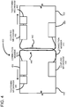
- FIG. 4 shows a side elevational view of a hinge 400 according to another embodiment wherein two flexible connection members 410, 420 are used in a cross-configuration.
- a first device 430 is coupled to a second device 432 end-to-end so that ends 440 and 442 are positioned adjacent one another.
- the connection member 410 is substantially S-shaped, while the connection member 420 is substantially a mirrored S-shape.
- the connection members 410, 420 cross each other as they pass between the ends 440, 442 of the devices 430, 432.
- Device 410 has a coupling mechanism 450 fixedly mounted on a back of the device 430 and a coupling mechanism 452 fixedly mounted on a front face of the device.
- connection member 410 is coupled to the coupling mechanism 450 on the back side of device 430, and to the coupling mechanism 456 on the front side of device 432.
- connection member 420 is connected at one end to coupling mechanism 452 on a front side of device 430 and to coupling mechanism 458 on a back side of device 432.
- Each flexible connection member 410, 420 is coupled to a respective tightening mechanism 460, 462.
- the tightening mechanisms 460, 462 can be used to increase tension on the connection members 410, 420 after assembly of the device.
- the cross configuration of the hinge 400 forces the ends 440, 442 to stay closely bound together while allowing the devices 430, 432 to rotate through a full 360 degrees with respect to one another, as was described in FIGS. 2A-2E .
- FIG. 5 shows a side elevational view of a hinge 500 according to another embodiment.
- a first device 510 is coupled to a second device 512 by the hinge 500.
- the first device 510 has a coupling member 520 with top and bottom sections 522, 524 adjacent to bottom and top faces 530, 532 of the device.
- the second device 512 includes a coupling member 540 having bottom and top sections 542, 544 adjacent to top and bottom faces 546, 548. How close the coupling member 540 is to the faces depends on a width 559 of the coupling member 540 from a middle of the device 512. The width 559 can be selected so that the hinge 500 does not protrude beyond the faces when the devices 510, 512 are rotated relative to each other.
- Coupling member 520 is generally sized equally to coupling member 540.
- a connection member 560 passes over the top section 522 of the coupling member 520 to form a bend and under a bottom section 542 of the coupling member 540 to form a reverse bend.
- the overall shape of connection member is a mirrored S-shape.
- a connection member 562 is similarly coupled in a mirrored S-shape path.
- the connection members 560, 562 are both coupled to a same tightening member 570 at one end and at an opposite end to a same tightening member 572.
- the tightening members 570, 572 can be moved in the direction shown by arrows adjacent thereto so as to increase tension on the connection members 560, 562.
- the tightening members 570, 572 can be wire termination devices that are e.g. injection molded with the connection members embedded therein. One tightening member can be sufficient. However, if two are used, tightening distance per tightening member can be halved so as to conserve space inside devices 510,512.
- FIG. 5 also shows screen displays 580, 582 on the top faces 532, 546 of the devices. The screen displays 580, 582 are aligned in a same plane to as to provide an appearance of one larger screen in a tablet mode.
- FIG. 6 shows an assembly drawing of an embodiment of a hinge 600 that can be used for coupling devices together.
- four wires 610 (two wire loop pairs) are used as the flexible connection members.
- the wires 610 are coupled between two wire termination blocks 612, 614.
- Each of the four wires 610 has either a substantially S-shape or a mirrored S-shape.
- An S-shape and mirrored S-shape loop with ends coupled in the wire termination blocks creates a substantially figure-eight shape.
- the wires 610 are mounted onto the coupling members, which in this case is a hinge lug 620 and an opposed hinge lug 622.
- the hinge lug 620 has two downward-sloping channels 630, 632, each one to accommodate one of the wires in a wire loop. As shown at 640, the channels come to a peak of the slope and then follow an outer perimeter of the hinge lug to extend along a hinge lug end, and then wrap around the bottom of the hinge lug. A channel divider 650 divides the channels 630, 632 to keep the wire loops in place. A tension screw 660 is threaded through a hole that passes through the hinge lug. The hinge lug 620 is coupled to a mounting plate 662 having holes for receiving screws to mount the hinge lug 620 to a face of the device. A friction hinge 670 is used to allow the devices to rotate with a free stop at any desired angle of rotation.
- the friction hinge 670 includes a rotatable male portion 680 having a cylindrical pin connector 684 that is coupled into a receptacle of a mounting bracket 686.
- a female portion 682 has a cavity therein for receiving the male portion so that they can be rotatably and slidably coupled together.
- the female portion 682 also includes a cylindrical connector to rotatably mount to a friction clip within a mounting bracket 690. Both mounting brackets 686 and 690 have holes for receiving mounting screws for mounting the brackets to the devices.
- the combination of the hinge 600 and friction hinge 670 allows two devices to be coupled together and rotate relative to each other through 360 degrees with a free stop in any position. With the free stop feature, a user can release the displays at any position and they will stay in that position.
- FIG. 7 shows the hinge 600 of FIG. 6 assembled and ready to be mounted to first and second devices 710, 712.
- Each device 710, 712 has a respective cutout to form an opening 720 into which the assembled hinge 600 can sit.
- Threaded mounting holes 730, 732 can be used to receive screws located in mounting plates 740, 742 so as to couple both devices 710, 720 to the hinge 600.
- the hinge 600 mounted into the devices 710, 712 is shown at 740.
- FIG. 8 is a top-down view of an embodiment of a hinge assembly 810 allowing a 360 degree range of motion.
- a friction hinge 820 is positioned adjacent to the hinge assembly 810 and can allow a free stop (a holding action) at any point of rotation.
- the hinge assembly 810 includes two hinge lugs 830, 832 positioned end-to-end and held together with four wires 840, 842, 844, 846, coupled to termination devices 850, 852.
- the adjustment screws 860, 862 are threaded through the hinge lugs 830, 832 and press on the termination devices 850, 852 so as to increase tension in the wires 840, 842, 844, 846.
- a cross-sectional view 870 is shown along lines A-A.
- the wire 846 follows a generally S-shaped path while the wire 844 follows a mirrored S-shape path. Together they form an elongated figure-eight shape or otherwise two back-to-back pear shapes. In either case, a closed-loop pattern is formed by the combination of two separate wires.
- the hinge lug 830 has a channel in which the wire 844 sits. The channel has a peak 880 that slopes downwardly as it approaches the termination device 850.
- the channel extends down an end face of the hinge lug 830 before wrapping around an opposed peak 882 and sloping upwardly to the termination device 850.
- the peaks 880 and 882 can align with the front and back faces of the devices so as to ensure that the hinge does not extend beyond the faces when rotating.
- the opposed peaks 880, 882 are used to couple different wires 884, 846, respectively, and to form bends or reverse bends as the wires pass within the channel.
- each wire passes from one termination device (e.g., 850) through part of the channel on one of the hinge lugs, between ends of the hinge lugs, into a channel on the opposed hinge lug, and finally to the termination device (e.g., 852) on the other device.
- the two hinge lugs 830, 832 thereby combine to provide a bend and reverse bend in the wires as the wires pass over the peaks of the hinge lugs.
- the wires terminate in a same horizontal plane within the termination devices 850, 852 so as to provide even tension on the wires.
- a cross-sectional view 890 is shown along lines B-B.
- the adjustment screw 860 includes a head 892 that can be screwed when the hinge lug is bent to expose the screw. In this way, the tension on the wires can be increased after manufacture and at any time during the life of the devices by merely rotating (pivoting) the devices relative to each other at a sufficient angle to expose the screw head 892.
- FIG. 2E is an example configuration wherein the screw heads for each hinge lug are exposed.
- the screw 860 threads in a hole that extends through the hinge lug 832 and extends into a recess 894 of the termination device 852. Screwing of the screw 890 tightens multiple wires simultaneously and pulls the devices together with increased force.
- FIG. 9 shows a series of images with two devices in a closed position and opening to a tablet position and the relative positions of the hinge lugs and the friction hinge during the rotational movement between the devices.
- a first device 910 and a second device 912 are shown in a closed position at 920.
- a friction hinge has a male portion 930 and a female portion 932 that sit in a vertical position.
- the wires, such as wire 934 pass from one side of device 910 to an opposite side of device 912 and are bent around the hinge lugs, as already described. While the wires are bent, they are in more of a U-shape configuration.
- the device 910 rotates to create a 30 angle between it and the second device 932.
- the devices 930, 932 are at about a 100 degree angle.
- the flexible wire 934 bends as the rotation is occurring. If a user releases a grip on the devices, they will stay in the illustrated position due to the friction hinge.
- the device halves are rotating with high tension in the wire to keep the device halves together.
- the device is in a tablet position and the wires move into a substantially S-shaped configuration and mirrored S-shape configuration.
- the wires transformed configuration from a substantially U-shaped configuration to a substantially S-shaped configuration.
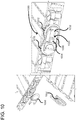
- FIG. 10 shows an example of a hinge assembly 1000 including first and second friction hinges 1010 and 1012 coupled together through a geared connection, shown generally at 1020.
- Friction hinges are a term used in the art and are also called Constant Torque Hinge, Position Hinge, Clutch hinge, or Detent Hinge.
- the term friction hinge is meant to include any hinge wherein at least two devices can be rotated relative to each other with a free stop feature wherein a user can release the devices and due to the holding force of the friction hinges, the devices remain in their respective position.
- friction hinges are used in laptop computers, for example.
- the friction hinge 1010 is a male friction hinge having an elongated extension member 1030 with an elongated slot 1032 formed therein.
- the extension member is symmetrical on top and bottom.
- the female friction hinge 1012 includes a recess in which the extension member 1030 is positioned.
- the female friction hinge 1012 also includes a pin 1034 sized to fit within the elongated slot 1032.
- the pin 1034 and slot 1032 form a geared pin-and-slot joint to ensure that the male and female friction hinges 1010 and 1012 are coupled together while being able to cooperatively slide in a radial direction. More particularly, the pin 1034 and slot 1032 prevents the male and female friction hinges 1010, 1012 from separating.
- a cap member 1050 is snapped onto the top of the hinge assembly 1000 using the pin 1034 and a mating pin receptacle 1052.
- the hinge assembly 1000 allows male and female friction hinges 1010, 1012 to be coordinately coupled so that they can rotate together in unison and can slide radially relative to each other so as to provide smooth rotational operation.
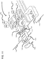
- FIG 11 shows an assembly drawing of the hinge assembly 1000.
- the male friction hinge 1010 includes a coupling portion 1110 that comprises the elongated extension member 1030 having the slot 1032 formed therein.
- the male friction hinge 1010 also includes a pin 1112 extending perpendicularly to the coupling portion 1110.
- the pin 1112 is sized to fit within a female receptacle 1116 with a friction fit to form a first axis of rotation.
- the female friction hinge 1012 has a coupling portion with a recess 1120 formed therein that is sized to fit the elongated extension member 1030 of the male friction hinge 1010.
- the female friction hinge 1012 also includes a pin 1130 that is sized to fit within a female receptacle 1132 with a friction fit to form a second axis of rotation.
- the female receptacles 1116, 1132 are shown as a slotted clip, but other types of female receptacles can be used such as a friction disk, a "question-mark" band, a roll pin, a tapered shaft, etc.
- the female receptacle 1116 is coupled to a mounting plate 1140, which mounts to a device 1150 using screws 1152 and mounting holes 1154 located on the device.
- the female friction hinge 1012 also includes a mounting plate 1142 that mounts to the other device 1160 using screws 1162.
- Both pins 1112, 1130 rotate within the female receptacles 1116, 1132 to create two axes of rotation.
- the coupling portion 1110 of the male friction hinge is coupled within the recess 1120 of the female friction hinge 1012, the two axes of rotation about pins 1112, 1130 are rotated in unison through the mutual gearing between the friction hinges 1010, 1012.
- there is a level of load sharing between the friction hinges to provide additional ability to free stop the devices 1150, 1160 as they are rotated relative to one another.
- the female and male friction hinges 1010, 1012 cooperatively slide in a radial direction towards and away from each other as the devices 1150, 1160 rotate relative to each other.
- FIG. 12 shows a hinge assembly 1200 according to another embodiment.
- the friction hinge 1210 is a male friction hinge having an elongated extension member 1230 that extends within a recess 1240 of the female friction hinge 1220.
- the elongated extension member 1230 can slide in a radial direction so that coupling portions 1250, 1252 move towards and away from each other as they rotate in unison.
- the friction hinges 1210, 1220 rotate on axes 1260, 1262 due to pins (not shown) extending perpendicularly to the coupling portions 1250, 1252.
- the friction hinges 1210, 1220 also include mounting plates 1270, 1272 for securing the friction hinges to devices 1280, 1282 that rotate relative to each other and that can be stopped at any rotational position due to the cooperative holding force generated by the friction hinges 1210, 1220 and the cooperative nature of the coupling portions 1250, 1252. For example, holding forces generated by one of the friction hinges can be passed to the other friction hinge through the male/female connection 1230, 1240.
- FIG. 13 is an assembly diagram of the hinge assembly 1200.
- the friction hinge 1210 includes the coupling portion 1250 including the elongated extension member 1230.
- the elongated extension member 1230 includes a keyed bottom end 1310 and a smooth top portion 1312.
- a top portion 1312 of the elongated extension member 1230 can be asymmetrical with the keyed bottom portion.
- the friction hinge 1210 further includes a pin 1320 extending along a rotational axis and perpendicular to the coupling portion 1250.
- the frictional hinge further includes the mounting plate 1270, which includes a female receptacle 1330 therein sized for receiving the pin 1320 with a friction fit.
- the female receptacle is a slotted clip that exerts a force on the pin 1320 due to the pin being slightly larger than the female receptacle.
- Other types of female receptacles can be used as outlined above.
- the female friction hinge 1220 includes the coupling portion 1252, which has a recess 1240 therein sized so that the elongate extension member 1230 fits within the recess 1240 with a friction fit. In this way, rotation of the coupling portion 1252 can generate a force on the side walls 1310, 1312 to transfer rotational force between the coupling members 1250, 1252.
- the female friction hinge 1220 also includes a pin 1350 that is positioned within a female receptacle 1352 of the mounting plate 1272.
- the mounting plate 1272 is coupled to the device 1282 using a bracket 1360 having threaded holes for receiving screws, which extend through the mounting plate 1272.
- the friction hinges can be coupled so as to have a friction fit there between.
- a friction fit can be accomplished with a male/female connection, but other connection techniques can be used.
- a geared coupling can be used to ensure that rotational energy is transferred between the first friction hinge and the second friction hinge. Additionally, it is desirable that the connection is such that the frictional hinges can move towards and away from each other to ensure smooth rotation of the devices.
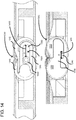
- FIG. 14 shows cross-sectional views of two coupling techniques for the friction hinges.
- a first friction hinge 1010 is rotationally coupled to a second friction hinge 1012 so that they rotate in unison.
- the geared connection 1020 is designed to allow radial movement of the friction hinges with respect to each other.
- the elongated slot 1032 can allow radial movement of the frictional hinges 1010, 1012 a distance "D", as indicated at 1410.
- the pin 1034 ensures that the frictional hinges move along a predefined line and ensures that the hinges do not decouple.
- first and second coupling portions 1250, 1252 are coupled together through a keyed elongated extension member 1230.
- the recess 1240 is sized so as to allow radial movement of the frictional hinges a distance "D", as indicated at 1420.
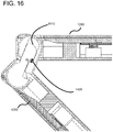
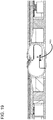
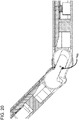
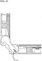
- FIGs. 15 through 23 show a progression of the frictional hinges as they move through a 360 degree cycle.
- the distance D shown at 1420 is at its maximum and the elongate extension member's end point 1510 is positioned at the end of the recess.
- the devices are in a fully open position with display surfaces 1520, 1530 outwardly positioned.
- FIG. 16 shows the frictional hinges as the devices 1280, 1282 are opened to about 30 degrees. Due to the dual friction hinges, the device 1280 can be held while releasing device 1282 and device 1282 will remain at its current position.
- FIG. 17 shows the devices 1280, 1282 at a 90 degree angle relative to each other.
- FIG. 18 shows that as the devices approach 180 degrees, the distance D, shown at 1420 increases with respect to FIG. 17 .
- FIG. 19 shows the devices at 180 degrees with the distance D at its maximum.
- FIG. 20 shows that as the devices approach 270 degrees of rotation, the keyed elongate member continues to move within the recess.
- FIG. 21 again shows the elongate member such that it restricts any further separation between the hinges due to the keyed end, as described above.
- the distance D which represents a radial movement of the friction hinges with respect to each other, dynamically changes as the devices are rotated.
- FIGs. 22 and 23 show about 300 degrees and 360 degrees respectively.
- FIG. 23 shows the devices in the closed position with the screens being not viewable.
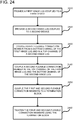
- FIG. 24 is a flowchart of a method according to one embodiment for connecting first and second devices.
- a first hinge lug is coupled to the first device.
- a second hinge lug is coupled to a second device.
- a first flexible connection member is coupled from a bottom channel of the first hinge lug to a top channel of the second hinge lug.
- a second flexible connection member is coupled in the top channel of the first hinge lug and the bottom channel of the second hinge lug, so that the first and second flexible connection members are in a cross configuration.
- the first and second flexible connection members are coupled to a termination block.
- the first and second flexible connection members are tightened using the termination block.
- FIG. 25 is a flowchart of a method according to one embodiment for coupling at least two different types of friction hinges.
- a first mounting plate is provided and coupled to the first device.
- a second mounting plate is provided and coupled to the second device.
- a pin of a male friction hinge is inserted into the first mounting plate.
- a pin of a female friction hinge is inserted into the second mounting plate.
- an elongated extension member of the male friction hinge is inserted into the female friction hinge to interconnect the two friction hinges together.
- two different types of friction hinges are connected together so as to coordinate rotational movement as the first and second devices rotate relative to one another.
- the devices described herein can be any of a variety of electronic devices including a laptop, notebook, netbook, or the like.
- One or more of the devices can include touchscreen capabilities.
- Touchscreens can accept input in different ways. For example, capacitive touchscreens detect touch input when an object (e.g., a fingertip or stylus) distorts or interrupts an electrical current running across the surface.
- touchscreens can use optical sensors to detect touch input when beams from the optical sensors are interrupted. Physical contact with the surface of the screen is not necessary for input to be detected by some touchscreens.
- Devices without screen capabilities also can be used in example environment.
- system and “device” are used interchangeably herein. Unless the context clearly indicates otherwise, neither term implies any limitation on a type of computing system or computing device. In general, a computing system or device can include any combination of special-purpose hardware and/or general-purpose hardware with software implementing the functionality described herein.
Landscapes
- Engineering & Computer Science (AREA)
- Theoretical Computer Science (AREA)
- Computer Hardware Design (AREA)
- Physics & Mathematics (AREA)
- General Physics & Mathematics (AREA)
- General Engineering & Computer Science (AREA)
- Human Computer Interaction (AREA)
- Mechanical Engineering (AREA)
- Computer Networks & Wireless Communication (AREA)
- Signal Processing (AREA)
- Mathematical Physics (AREA)
- Pivots And Pivotal Connections (AREA)
- Telephone Set Structure (AREA)
Claims (7)
- Scharnierbaugruppe (1200), aufweisend:eine erste Befestigungsplatte (1272) aufweisend eine erste Aufnahmebuchse (1352), in welcher eine erste Achse (1262) definiert ist;eine zweite Befestigungsplatte (1270) aufweisend eine zweite Aufnahmebuchse (1330), in welcher eine zweite Achse (1260) definiert ist;ein Aufnahmereibungsscharnierelement (1220), in welchem eine Vertiefung (1240) definiert ist, wobei sich die Vertiefung (1240) lotrecht zur ersten Achse (1262) und zur zweiten Achse (1260) von einem offenen ersten Ende zu einem geschlossenen zweiten Ende erstreckt, das Aufnahmereibungsscharnierelement (1220) ferner aufweisend einen längserstreckten Stift (1320) zur Befestigung innerhalb der ersten Aufnahmebuchse (1352); undein Zapfenreibungsscharnierelement (1210) aufweisend einen längserstreckten Stift (1320) zur Befestigung innerhalb der zweiten Aufnahmebuchse (1330), das Zapfenreibungsscharnierelement (1210) ferner aufweisend ein längserstrecktes Verlängerungselement (1230), welches sich lotrecht zur ersten Achse (1262) und zur zweiten Achse (1260) erstreckt, wobei das längserstreckte Verlängerungselement (1230) innerhalb der Vertiefung (1240) des Aufnahmereibungsscharnierelements (1220) abgestimmt auf dieselbe derart gekoppelt ist, dass sich das Aufnahmereibungsscharnierelement (1220) und das Zapfenreibungsscharnierelement (1270) gemeinsam drehen.
- Scharnierbaugruppe nach Anspruch 1, wobei die längserstreckte Verlängerung (1230) des Zapfenreibungsscharnierelements (1210) innerhalb der Vertiefung (1240) des Aufnahmereibungsscharnierelements (1220) verschiebbar derart gekoppelt ist, dass das Zapfenreibungsscharnierelement (1210) und das Aufnahmereibungsscharnierelement (1220) in einer Richtung radial zur ersten Achse (1262) und zur zweiten Achse (1260) zusammenwirkend aufeinander zu und voneinander weg gleiten.
- Scharnierbaugruppe nach irgendeinem der Ansprüche 1 - 2, wobei das Verlängerungselement (1230) innerhalb der Vertiefung (1240) des Aufnahmereibungsscharnierelements (1220) reibschlüssig im Eingriff steht.
- Scharnierbaugruppe nach irgendeinem der Ansprüche 1 - 3, wobei sich das Aufnahmereibungsscharnierelement (1220) und das Zapfenreibungsscharnierelement (1210) rund um parallele Achsen (1260, 1262) drehen, und wobei das längserstreckte Verlängerungselement (1230) derart formschlüssig ausgebildet ist, dass es eine Radialbewegung in Bezug auf die erste Achse (1262) und die zweite Achse (1260) zwischen dem Aufnahmereibungsscharnierelement (1220) und dem Zapfenreibungsscharnierelement (1210) mit einem Anschlag, um eine Trennung von diesen zu verhindern, ermöglicht.
- Scharnierbaugruppe nach irgendeinem der Ansprüche 1 - 4, wobei die erste Aufnahmebuchse (1352) der ersten Befestigungsplatte (1272) eine geschlitzte Klammer ist, in welche der längserstreckte Stift (1350) des Aufnahmereibungsscharnierelements (1220) mittels Reibungssitz eingesetzt ist.
- Scharnierbaugruppe nach irgendeinem der Ansprüche 1 - 5, wobei das längserstreckte Verlängerungselement (1230) eine erste (1310) und eine zweite Seite (1312) aufweist, welche asymmetrisch sind, und die Vertiefung (1240) derart geformt ist, dass sie der ersten Seite (1310) und der zweiten Seite (1312) angepasst ist, sodass das längserstreckte Verlängerungselement (1230) innerhalb der Vertiefung (1240) gleiten kann.
- Scharnierbaugruppe nach irgendeinem der Ansprüche 1 - 4 oder 6, wobei die erste Aufnahmebuchse (1352) oder die zweite Aufnahmebuchse (1330) eines der folgenden Elemente sind: eine geschlitzte Klammer, ein Fragezeichenband, ein Spannstiftband oder ein konischer Schaft.
Applications Claiming Priority (2)
| Application Number | Priority Date | Filing Date | Title |
|---|---|---|---|
| US15/182,318 US10501973B2 (en) | 2016-06-14 | 2016-06-14 | Hinge with free-stop function |
| PCT/US2017/036256 WO2017218250A1 (en) | 2016-06-14 | 2017-06-07 | Hinge with free-stop function |
Publications (2)
| Publication Number | Publication Date |
|---|---|
| EP3469449A1 EP3469449A1 (de) | 2019-04-17 |
| EP3469449B1 true EP3469449B1 (de) | 2020-07-22 |
Family
ID=59067921
Family Applications (1)
| Application Number | Title | Priority Date | Filing Date |
|---|---|---|---|
| EP17730639.6A Active EP3469449B1 (de) | 2016-06-14 | 2017-06-07 | Scharnier mit freistoppfunktion |
Country Status (4)
| Country | Link |
|---|---|
| US (2) | US10501973B2 (de) |
| EP (1) | EP3469449B1 (de) |
| CN (1) | CN109416559B (de) |
| WO (1) | WO2017218250A1 (de) |
Families Citing this family (33)
| Publication number | Priority date | Publication date | Assignee | Title |
|---|---|---|---|---|
| US10301858B2 (en) * | 2016-06-14 | 2019-05-28 | Microsoft Technology Licensing, Llc | Hinge mechanism |
| JP6659969B2 (ja) * | 2017-04-07 | 2020-03-04 | 富士通クライアントコンピューティング株式会社 | 端末装置 |
| CN107479627A (zh) * | 2017-07-19 | 2017-12-15 | 武汉华星光电技术有限公司 | 笔记本与平板二合一电脑 |
| USD915394S1 (en) * | 2017-11-22 | 2021-04-06 | Compal Electronics, Inc. | Notebook computer |
| USD915395S1 (en) * | 2018-02-13 | 2021-04-06 | Compal Electronics, Inc. | Notebook computer |
| USD917460S1 (en) * | 2018-02-13 | 2021-04-27 | Compal Electronics, Inc. | Notebook computer |
| USD885379S1 (en) * | 2018-02-14 | 2020-05-26 | Compal Electronics, Inc. | Notebook computer |
| KR102031262B1 (ko) * | 2018-03-27 | 2019-10-11 | 주식회사 우보테크 | 헤드레스트 윙 조절 장치 |
| US11091944B2 (en) * | 2018-03-28 | 2021-08-17 | Microsoft Technology Licensing, Llc | Hinged device |
| TWI727294B (zh) * | 2018-04-13 | 2021-05-11 | 仁寶電腦工業股份有限公司 | 樞軸模組及電子裝置 |
| KR102488408B1 (ko) * | 2018-06-22 | 2023-01-16 | 삼성전자주식회사 | 자성체를 포함하는 전자 장치 |
| US11181950B2 (en) * | 2018-07-24 | 2021-11-23 | Microsoft Technology Licensing, Llc | Hinged device |
| USD904331S1 (en) * | 2018-11-29 | 2020-12-08 | Lg Electronics Inc. | Mobile phone |
| WO2020146049A1 (en) * | 2019-01-11 | 2020-07-16 | Incadence Strategic Solutions Corporation | Mobile modular folding biometric apparatus |
| US10503217B1 (en) * | 2019-02-15 | 2019-12-10 | Dell Products L.P. | Cable retention mechanism |
| US11106248B2 (en) | 2019-04-10 | 2021-08-31 | Microsoft Technology Licensing, Llc | Hinged device |
| CN110219535B (zh) * | 2019-07-04 | 2023-08-22 | 九牧厨卫股份有限公司 | 一种可双向转动的合页以及应用该合页的淋浴房门及合页转动方法 |
| KR102910549B1 (ko) * | 2019-12-05 | 2026-01-12 | 삼성전자주식회사 | 폴더블 전자 장치 및 그것의 동작 방법 |
| US11009921B1 (en) | 2020-05-14 | 2021-05-18 | Apple Inc. | Electronic devices with adjustable hinges |
| WO2021236064A1 (en) * | 2020-05-19 | 2021-11-25 | Hewlett-Packard Development Company, L.P. | Hinges with rotational moving bars |
| US11455008B2 (en) * | 2020-06-29 | 2022-09-27 | Lenovo (Singapore) Pte. Ltd. | System hinge assembly |
| JP6970794B1 (ja) * | 2020-07-22 | 2021-11-24 | レノボ・シンガポール・プライベート・リミテッド | 電子機器及びヒンジ装置 |
| US11720151B2 (en) | 2020-08-03 | 2023-08-08 | Microsoft Technology Licensing, Llc | Hinged device |
| US11567543B2 (en) * | 2020-09-29 | 2023-01-31 | Microsoft Technology Licensing, Llc | Hinge assembly for mobile computing device |
| US11669132B2 (en) * | 2020-09-29 | 2023-06-06 | Microsoft Technology Licensing, Llc | Hinge assembly for mobile computing device |
| CN112177465B (zh) * | 2020-09-30 | 2022-10-11 | 环鸿电子(昆山)有限公司 | 枢转机构及掀盖装置 |
| CN214945705U (zh) * | 2021-02-25 | 2021-11-30 | 艺爵包装有限公司 | 一种铰链结构及包装盒 |
| SE544744C2 (en) * | 2021-04-01 | 2022-11-01 | Skugga Tech Ab | Hinge between a first part and a second part in an electrical device |
| TWI774316B (zh) * | 2021-04-12 | 2022-08-11 | 光磊科技股份有限公司 | 多向多關節轉折件及其顯示裝置 |
| TWI767830B (zh) * | 2021-08-30 | 2022-06-11 | 富世達股份有限公司 | 鉸鏈 |
| USD1067224S1 (en) * | 2022-12-30 | 2025-03-18 | Lg Electronics Inc. | Laptop computer |
| CN116291082B (zh) * | 2023-04-04 | 2025-10-31 | 奇点变幻科技(天津)有限公司 | 一种可360度旋转的铰链结构 |
| CN117548584B (zh) * | 2023-12-05 | 2026-02-24 | 无锡万华机械有限公司 | 一种带有辅助退料机构的汽车冲压模具 |
Family Cites Families (176)
| Publication number | Priority date | Publication date | Assignee | Title |
|---|---|---|---|---|
| US1819212A (en) | 1928-02-27 | 1931-08-18 | Hudson Motor Car Co | Doorstop strap |
| US1837517A (en) | 1930-01-13 | 1931-12-22 | Briggs Mfg Co | Check strap assembly |
| US1903923A (en) | 1931-06-02 | 1933-04-18 | Hyde William James | Closure-holding and return spring |
| US2568225A (en) | 1944-03-03 | 1951-09-18 | Victor P Doman | Door hinge |
| US2709275A (en) | 1952-06-09 | 1955-05-31 | Atwood Vacuum Machine Co | Automobile door hinge embodying hold-open means |
| US3016563A (en) | 1959-03-04 | 1962-01-16 | Jong George Edward De | Combined hinge and catch |
| USRE30861E (en) | 1967-12-11 | 1982-02-09 | Westhem Corporation Limited | Biased hinges |
| US3562850A (en) | 1968-08-13 | 1971-02-16 | Eliason Refrigerator Co | Magnetic door holder |
| US3588946A (en) | 1969-02-07 | 1971-06-29 | Cardinal Of Adrian | Hinge |
| CA1038569A (en) * | 1977-01-11 | 1978-09-19 | Her Majesty The Queen In Right Of Canada As Represented By The Minister Of National Defence Of Her Majesty's Canadian Government | Self-locking hinge |
| US4301570A (en) | 1979-08-16 | 1981-11-24 | International Harvester Company | Door check and holding device for a motor vehicle |
| US4393541A (en) * | 1980-02-19 | 1983-07-19 | General Dynamics Corporation/Convair Div. | Hinge for deployable structures self locking hinge |
| FR2532981B1 (fr) | 1982-09-14 | 1987-10-30 | Vuitton Sa Louis | Charniere perfectionnee sans axe rigide d'articulation |
| GB8804317D0 (en) | 1988-02-24 | 1988-03-23 | Heath Samuel & Sons Plc | Door closers |
| US5120030A (en) | 1991-05-28 | 1992-06-09 | General Motors Corporation | Magnet assisted liftgate strut |
| US5851634A (en) | 1992-08-11 | 1998-12-22 | E. Khashoggi Industries | Hinges for highly inorganically filled composite materials |
| US5566048A (en) * | 1994-06-02 | 1996-10-15 | Hewlett-Packard Company | Hinge assembly for a device having a display |
| US6135530A (en) | 1998-11-04 | 2000-10-24 | Lear Automotive Dearborn, Inc. | Spring loaded living hinge |
| KR100678082B1 (ko) | 1998-12-30 | 2007-05-17 | 삼성전자주식회사 | 폴더 타입 휴대폰에서 메인 보드와 엘씨디 모듈간의연결장치 |
| US6564428B2 (en) | 2000-01-14 | 2003-05-20 | Hoffman Enclosures, Inc. | Compound hinge |
| US6311367B1 (en) | 2000-03-22 | 2001-11-06 | Kenneth Duane Larsen | Apparatus and method for supporting a door in an open position |
| US6507485B2 (en) | 2001-01-04 | 2003-01-14 | Apple Computer, Inc. | Spring loaded hinge apparatus |
| US6659516B2 (en) | 2001-01-05 | 2003-12-09 | Apple Computer, Inc. | Locking system for a portable computer |
| DE50115305D1 (de) | 2001-03-29 | 2010-03-04 | Mueller Martini Holding Ag | Falzvorrichtung für Druckbogen |
| US6900984B2 (en) | 2001-04-24 | 2005-05-31 | Apple Computer, Inc. | Computer component protection |
| TW529879U (en) * | 2001-08-03 | 2003-04-21 | Benq Corp | Monitor support device |
| US6798649B1 (en) * | 2002-02-25 | 2004-09-28 | Think Outside, Inc. | Mobile computer with foldable keyboard |
| US6657856B1 (en) * | 2002-07-08 | 2003-12-02 | Lu Sheng-Nan | Hinge for a notebook computer |
| US6813812B2 (en) * | 2002-12-10 | 2004-11-09 | Shin Zu Shing Co., Ltd. | Hinge for a notebook computer |
| US6766562B1 (en) | 2003-01-09 | 2004-07-27 | Rite-Hite Holding Corporation | Extendible hinge |
| US6900981B2 (en) | 2003-04-23 | 2005-05-31 | Nokia Corporation | Mobile Terminal with synchronizing hinge |
| US7155266B2 (en) | 2004-04-21 | 2006-12-26 | Nokia Corporation | Hinge for fold phone |
| KR100556849B1 (ko) | 2003-05-13 | 2006-03-10 | 엘지전자 주식회사 | 휴대용 단말기의 카메라 모듈 연결장치 |
| US7127776B2 (en) | 2003-06-04 | 2006-10-31 | Lg Electronics Inc. | Dual display type portable computer and control method for the same |
| US6929291B2 (en) | 2003-07-28 | 2005-08-16 | Inventec Corp. | Magnetic lock |
| US7102441B2 (en) | 2003-12-31 | 2006-09-05 | Realtek Semiconductor Corp. | Variable gain amplifying circuit |
| TWM262965U (en) | 2004-04-09 | 2005-04-21 | Fih Co Ltd | Hinge structure |
| US20070182663A1 (en) | 2004-06-01 | 2007-08-09 | Biech Grant S | Portable, folding and separable multi-display computing system |
| KR100689532B1 (ko) | 2004-08-17 | 2007-03-02 | 삼성전자주식회사 | 휴대용 단말기의 이축 힌지 장치 |
| JP2006064000A (ja) * | 2004-08-24 | 2006-03-09 | Strawberry Corporation | ヒンジ装置並びにヒンジ装置を用いた電子機器 |
| EP1659764A1 (de) | 2004-11-19 | 2006-05-24 | Siemens Aktiengesellschaft | Zusammenklappbares schwenkgelenkloses Gerät der Informations- oder Kommunikationstechnik |
| JP4594936B2 (ja) * | 2005-02-15 | 2010-12-08 | スガツネ工業株式会社 | ヒンジ装置 |
| KR100652748B1 (ko) | 2005-07-19 | 2006-12-01 | 엘지전자 주식회사 | 엘시디모듈 및 이를 구비한 이동통신 단말기 |
| TWI275291B (en) | 2005-09-27 | 2007-03-01 | Asustek Comp Inc | Clam type mobile phone |
| JP4633613B2 (ja) | 2005-11-30 | 2011-02-16 | 富士通株式会社 | 折り畳み式電子機器 |
| US7667959B2 (en) | 2005-12-20 | 2010-02-23 | Nokia Corp. | Foldable electronic device having double-axis hinge and locking spring |
| US8582905B2 (en) | 2006-01-31 | 2013-11-12 | Qualcomm Incorporated | Methods and systems for rate control within an encoding device |
| TWM298152U (en) * | 2006-02-24 | 2006-09-21 | Lian Hong Art Co Ltd | X-shape tube strut of inge and hinge employing the same |
| US20070234521A1 (en) | 2006-04-06 | 2007-10-11 | Nokia Corporation | Double-axis hinge for use in electronic devices |
| TW200742794A (en) | 2006-05-11 | 2007-11-16 | shi-min Hong | Folding device for cordless blind |
| US20070283529A1 (en) | 2006-06-08 | 2007-12-13 | Nokia Corporation | Plastic living hinge with metal support |
| JP2008014449A (ja) * | 2006-07-07 | 2008-01-24 | Sugatsune Ind Co Ltd | 二軸ヒンジ装置 |
| TWI331503B (en) * | 2006-07-11 | 2010-10-01 | Compal Electronics Inc | Pivot mechanism and electonic apparatus using the same |
| JP2008078471A (ja) | 2006-09-22 | 2008-04-03 | Fujitsu Ltd | ケーブル配線構造、電子機器、その製造方法及びケーブル |
| CN101535663B (zh) * | 2006-11-06 | 2011-06-22 | 三菱制钢株式会社 | 铰接机构 |
| US7832056B2 (en) * | 2006-11-13 | 2010-11-16 | Panasonic Corporation | Opening-closing device |
| US7787912B2 (en) * | 2006-11-22 | 2010-08-31 | Nokia Corporation | Portable electronic device with double acting hinge arrangement |
| US7593524B2 (en) | 2006-11-27 | 2009-09-22 | Nokia Corporation | Hinge arrangement |
| US8364214B2 (en) | 2006-12-14 | 2013-01-29 | Nokia Corporation | Electrically released magnet locking mechanism |
| US20080151478A1 (en) * | 2006-12-21 | 2008-06-26 | Jr-Jiun Chern | Hinge for laptop computer |
| TWI321980B (en) | 2007-01-22 | 2010-03-11 | Qisda Corp | Foldable mobile electronic device |
| TWI468897B (zh) | 2007-04-25 | 2015-01-11 | Creator Technology Bv | 電子裝置 |
| US8099144B2 (en) | 2007-08-20 | 2012-01-17 | Google Inc. | Electronic device with hinge mechanism |
| US7779509B2 (en) * | 2007-11-21 | 2010-08-24 | Shin Zu Shing Co., Ltd. | Sliding hinge |
| CN101451573B (zh) * | 2007-12-06 | 2013-04-24 | 鸿富锦精密工业(深圳)有限公司 | 铰链结构 |
| CN101469736B (zh) * | 2007-12-27 | 2012-03-28 | 鸿富锦精密工业(深圳)有限公司 | 铰链结构 |
| CN101487558B (zh) * | 2008-01-16 | 2012-01-25 | 鸿富锦精密工业(深圳)有限公司 | 升降机构 |
| US20090229080A1 (en) * | 2008-03-17 | 2009-09-17 | Shin Zu Shing Co., Ltd. | Automated hinge assembly |
| DE102008013560B4 (de) * | 2008-03-28 | 2010-01-28 | E-LEAD ELECTRONIC CO., LTD., Shengang Shiang | Doppelachsenkonstruktion mit extremem Biegungswinkel |
| JP2009264460A (ja) | 2008-04-24 | 2009-11-12 | Sony Ericsson Mobilecommunications Japan Inc | 二軸ヒンジ装置、及び携帯端末装置 |
| CN102089729A (zh) | 2008-06-12 | 2011-06-08 | 卡诺瓦科技有限公司 | 双屏显示系统 |
| US8413382B2 (en) | 2008-09-02 | 2013-04-09 | Caterpillar Sarl | Hinge and door unit |
| US7922133B2 (en) | 2008-09-12 | 2011-04-12 | Shin Zu Shing Co., Ltd. | Flat panel display support |
| WO2010039707A1 (en) * | 2008-09-30 | 2010-04-08 | Brown Garrett W | Biased hinge for equipoising support equipment |
| CN101737421A (zh) | 2008-11-25 | 2010-06-16 | 深圳富泰宏精密工业有限公司 | 铰链机构及应用该铰链机构的便携式电子装置 |
| CN201351676Y (zh) * | 2008-12-10 | 2009-11-25 | 康准电子科技(昆山)有限公司 | 枢纽器 |
| US7971321B2 (en) * | 2008-12-19 | 2011-07-05 | Shin Zu Shing Co., Ltd. | Hinge and an electronic device with the hinge |
| US7752711B1 (en) * | 2008-12-24 | 2010-07-13 | Shin Zu Shing Co., Ltd. | Hinge and an electronic device with the hinge |
| KR101408951B1 (ko) | 2009-01-07 | 2014-06-17 | 삼성전자주식회사 | 스탠드 장치 |
| US8746645B2 (en) | 2009-03-02 | 2014-06-10 | Fellowes, Inc. | Laptop riser |
| CN102349281B (zh) | 2009-03-13 | 2014-04-16 | 约吉诗·库马尔·坎耶 | 包括滑动部分和折叠部分的移动电话 |
| CN101852329A (zh) | 2009-04-01 | 2010-10-06 | 鸿富锦精密工业(深圳)有限公司 | 显示设备 |
| US8804317B2 (en) | 2009-07-01 | 2014-08-12 | Sharp Kabushiki Kaisha | Display device |
| US8074323B2 (en) * | 2009-08-01 | 2011-12-13 | Shin Zu Shing Co., Ltd. | Inverted-type hinge and a portable electronic device |
| US8549710B2 (en) * | 2009-08-30 | 2013-10-08 | Southco, Inc. | Hinge assembly with a multi-layer torsion bar spring |
| US20110099756A1 (en) * | 2009-11-04 | 2011-05-05 | Tonny Chen | Wide-angle double-hinge structure |
| TWM400736U (en) | 2010-04-15 | 2011-03-21 | Lian Hong Art Co Ltd | 360 degrees rotatable bi-directional hinge |
| JP2011256957A (ja) | 2010-06-10 | 2011-12-22 | Sony Corp | 二軸ヒンジ機構及び電子機器 |
| US8143982B1 (en) | 2010-09-17 | 2012-03-27 | Apple Inc. | Foldable accessory device |
| US8982542B2 (en) * | 2010-11-17 | 2015-03-17 | Microsoft Technology Licensing, Llc | Hinge mechanism for mobile electronic device |
| US20120154999A1 (en) | 2010-12-15 | 2012-06-21 | Samsung Electronics Co., Ltd. | Electronic apparatus |
| US8438702B2 (en) | 2011-01-06 | 2013-05-14 | Nokia Corporation | Flexible hinge for electronic devices |
| US8451601B2 (en) * | 2011-01-31 | 2013-05-28 | Microsoft Corporation | Double hinge axial cams |
| KR101174687B1 (ko) | 2011-03-23 | 2012-08-16 | 주식회사 파인테크닉스 | 휴대단말기용 복층 스윙힌지 |
| US8804324B2 (en) * | 2011-06-03 | 2014-08-12 | Microsoft Corporation | Flexible display overcenter assembly |
| US8787016B2 (en) * | 2011-07-06 | 2014-07-22 | Apple Inc. | Flexible display devices |
| EP4386725B1 (de) | 2011-07-11 | 2026-05-06 | Samsung Electronics Co., Ltd. | Flexible anzeige mit anzeigeträger |
| TWI485345B (zh) | 2011-09-20 | 2015-05-21 | Compal Electronics Inc | 顯示器支撐架 |
| US8891232B2 (en) | 2011-09-23 | 2014-11-18 | Htc Corporation | Support stand and standable hand-held device |
| US9351237B2 (en) | 2011-09-27 | 2016-05-24 | Z124 | Displaying of charging status on dual screen device |
| US9201464B2 (en) | 2011-11-28 | 2015-12-01 | Lenovo (Beijing) Co., Ltd. | Terminal apparatus |
| CN103167068B (zh) | 2012-03-26 | 2016-12-28 | 联想(北京)有限公司 | 一种电子终端 |
| US20130293444A1 (en) | 2012-05-02 | 2013-11-07 | Sony Mobile Communications Ab | Mobile terminal |
| TWI502142B (zh) | 2012-05-17 | 2015-10-01 | Wistron Corp | 易於拆裝之樞軸機構及其電子裝置 |
| JP5704613B2 (ja) * | 2012-05-30 | 2015-04-22 | 株式会社ナチュラレーザ・ワン | 2軸ヒンジ |
| US8908365B2 (en) | 2012-06-25 | 2014-12-09 | Creator Technology B.V. | Display system having a continuous flexible display with display supports |
| US9264713B2 (en) | 2012-07-11 | 2016-02-16 | Qualcomm Incorporated | Rotation of prediction residual blocks in video coding with transform skipping |
| TWI602490B (zh) * | 2012-07-31 | 2017-10-11 | 宏碁股份有限公司 | 折疊式電子設備 |
| US8971031B2 (en) | 2012-08-07 | 2015-03-03 | Creator Technology B.V. | Display system with a flexible display |
| US9158332B2 (en) | 2012-10-22 | 2015-10-13 | Nokia Technologies Oy | Limiting movement |
| US20140123436A1 (en) | 2012-11-02 | 2014-05-08 | Research In Motion Limited | Support for a flexible display |
| TWM453753U (zh) | 2012-12-21 | 2013-05-21 | First Dome Corp | 多節式轉軸結構 |
| TW201426095A (zh) | 2012-12-26 | 2014-07-01 | Syncmold Entpr Corp | 用於支撐顯示面板的相框式支撐裝置 |
| KR101452871B1 (ko) | 2013-01-11 | 2014-10-22 | (주) 프렉코 | 접철 가능한 플렉시블 디스플레이 장치 |
| KR101452872B1 (ko) * | 2013-01-11 | 2014-11-03 | (주) 프렉코 | 디스플레이장치의 힌지장치 |
| US9201465B2 (en) * | 2013-03-15 | 2015-12-01 | Dell Products L.P. | Information handling system housing lid with synchronized motion |
| JP6197327B2 (ja) * | 2013-03-27 | 2017-09-20 | 富士通株式会社 | 電子機器 |
| US9856079B2 (en) | 2013-04-09 | 2018-01-02 | Grigooris MANSSOURIAN | Retainer mechanism |
| US8978206B2 (en) * | 2013-05-16 | 2015-03-17 | First Dome Corporation | Dual-shaft synchronous motion device |
| US9353561B2 (en) * | 2013-06-10 | 2016-05-31 | Ronnie GAENZLE | 180 degree foldable locking hinge |
| US9310850B2 (en) * | 2013-06-11 | 2016-04-12 | First Dome Corporation | Synchronous movement device applied to dual-shaft system |
| US9500013B2 (en) * | 2013-07-25 | 2016-11-22 | Hewlett-Packard Development Company, L.P. | Hinge assembly for a computing device |
| WO2015023698A1 (en) * | 2013-08-13 | 2015-02-19 | FlatZen, Inc. | Hinge mechanisms and foldable furniture |
| KR101663728B1 (ko) | 2013-08-26 | 2016-10-07 | 삼성전자주식회사 | 플렉서블 디스플레이 소자를 구비한 접철식 전자 기기 |
| US9632530B2 (en) * | 2013-08-26 | 2017-04-25 | Hewlett-Packard Development Company, L.P. | Display panel responsive key retraction |
| GB2517782B (en) | 2013-09-02 | 2020-08-19 | Nokia Technologies Oy | An apparatus and method of providing an apparatus comprising a bendable portion |
| GB2521152A (en) | 2013-12-10 | 2015-06-17 | Nokia Technologies Oy | An apparatus and method of providing an apparatus comprising a bendable portion |
| KR102215597B1 (ko) * | 2013-12-23 | 2021-02-15 | 삼성전자주식회사 | 전자기기 |
| US9551177B2 (en) | 2013-12-26 | 2017-01-24 | Intel Corporation | Rotational to translational locking hinge |
| TWM483648U (zh) * | 2013-12-31 | 2014-08-01 | First Dome Corp | 用於雙轉軸之傳動穩定裝置 |
| EP3094804A1 (de) | 2014-01-06 | 2016-11-23 | Dbci | Türsystem mit ineinandergreifenden rollenden blättern |
| US9798359B2 (en) | 2014-02-21 | 2017-10-24 | Samsung Electronics Co., Ltd. | Foldable device |
| TWM483642U (zh) * | 2014-02-25 | 2014-08-01 | First Dome Corp | 用於雙轉軸之平行度控制裝置 |
| US20150277506A1 (en) | 2014-03-29 | 2015-10-01 | Bok Eng Cheah | Micro-hinge for an electronic device |
| US20150282354A1 (en) | 2014-04-01 | 2015-10-01 | Logitech Europe S.A. | Multi viewing angle portable electronic device support |
| TWI533787B (zh) * | 2014-04-29 | 2016-05-11 | 洪進興 | 穩定轉動之雙軸轉軸 |
| US9181737B1 (en) | 2014-06-03 | 2015-11-10 | Whirlpool Corporation | Oven door opening magnetic hinge |
| US9684343B2 (en) * | 2014-06-12 | 2017-06-20 | Microsoft Technology Licensing, Llc | Radius hinge |
| CN105179459B (zh) * | 2014-06-12 | 2021-01-22 | 加藤电机(香港)有限公司 | 双轴铰链及应用此双轴铰链的终端机器 |
| KR102201928B1 (ko) | 2014-06-24 | 2021-01-12 | 삼성전자주식회사 | 플렉시블 장치 및 그의 접이 장치 |
| US9715255B2 (en) * | 2014-06-27 | 2017-07-25 | Intel Corporation | Belt driven hinge assembly for electronic devices |
| US9563236B2 (en) * | 2014-07-11 | 2017-02-07 | Intel Corporation | Adjustable tension wrap end hinge |
| TWI603007B (zh) * | 2014-07-31 | 2017-10-21 | First Dome Corp | Double shaft synchronous drive fixing device |
| TWI549594B (zh) * | 2014-09-18 | 2016-09-11 | 宏碁股份有限公司 | 轉軸結構 |
| US9476238B2 (en) | 2014-09-25 | 2016-10-25 | William Scott Mooers | Hinge providing an opening or closing force |
| US9447620B2 (en) | 2014-09-30 | 2016-09-20 | Microsoft Technology Licensing, Llc | Hinge mechanism with multiple preset positions |
| JP6590135B2 (ja) * | 2014-10-14 | 2019-10-16 | 株式会社ナチュラレーザ・ワン | 2軸ヒンジ及びこの2軸ヒンジを用いた電子機器 |
| US9290976B1 (en) * | 2014-10-22 | 2016-03-22 | Chin-Hsing Horng | Position-limit hinge |
| US9910465B2 (en) | 2014-11-11 | 2018-03-06 | Microsoft Technology Licensing, Llc | Covered radius hinge |
| US20160139635A1 (en) | 2014-11-17 | 2016-05-19 | Infocase, Inc. | Protective case for hybrid computer |
| US9851759B2 (en) | 2014-12-31 | 2017-12-26 | Microsoft Technology Licensing, Llc | Multi-pivot hinge cover |
| CN105822659B (zh) * | 2015-01-09 | 2018-06-19 | 至美波特有限公司 | 双向铰链 |
| CN204533165U (zh) | 2015-01-29 | 2015-08-05 | 东莞市橙工电子科技有限公司 | 滑块轨道型双铰链360度转轴 |
| TWM508189U (zh) * | 2015-02-11 | 2015-09-01 | First Dome Corp | 組合樞軸之傳動裝置 |
| US10365691B2 (en) | 2015-04-09 | 2019-07-30 | Samsung Electronics Co., Ltd. | Foldable device |
| US9828795B1 (en) * | 2015-04-28 | 2017-11-28 | Wayne W. Ramsdell | Hinge and applications thereof |
| KR102414855B1 (ko) | 2015-04-30 | 2022-07-01 | 삼성전자주식회사 | 플렉시블 전자 장치 |
| US9366064B1 (en) * | 2015-05-29 | 2016-06-14 | Lianhong Art Co., Ltd. | Hinge structure |
| CN204782418U (zh) | 2015-06-30 | 2015-11-18 | 李思模 | 用于门的铰链 |
| US9971379B2 (en) | 2015-08-26 | 2018-05-15 | Apple Inc. | Attachment features for an accessory device |
| KR102366299B1 (ko) | 2015-08-31 | 2022-02-21 | 엘지디스플레이 주식회사 | 플렉서블 디스플레이용 지지 프레임 및 이를 포함하는 플렉서블 디스플레이 장치 |
| KR102366516B1 (ko) | 2015-08-31 | 2022-02-22 | 엘지디스플레이 주식회사 | 접이식 디스플레이 장치 |
| EP3153404B1 (de) | 2015-10-06 | 2020-09-23 | Safran Landing Systems UK Limited | Flugzeugbaugruppe |
| CN205159734U (zh) | 2015-10-28 | 2016-04-13 | 宝兴县剑锋制箔电子有限公司 | 碳刷加电式导电铝辊 |
| KR101814067B1 (ko) | 2015-11-06 | 2018-01-02 | (주) 프렉코 | 절첩식 디스플레이 장치 |
| US20170145724A1 (en) | 2015-11-20 | 2017-05-25 | Microsoft Technology Licensing, Llc | Hinged device |
| US10227808B2 (en) | 2015-11-20 | 2019-03-12 | Microsoft Technology Licensing, Llc | Hinged device |
| US9964988B2 (en) * | 2015-12-22 | 2018-05-08 | Intel Corporation | Hinge clip |
| JP2017134758A (ja) | 2016-01-29 | 2017-08-03 | 富士通株式会社 | 情報処理装置 |
| US9624704B1 (en) * | 2016-03-25 | 2017-04-18 | First Dome Corporation | Pivot pin device |
| CN107228119B (zh) * | 2016-03-25 | 2020-02-28 | 加藤电机(香港)有限公司 | 双轴铰链及使用此双轴铰链的终端机器 |
| US10301858B2 (en) | 2016-06-14 | 2019-05-28 | Microsoft Technology Licensing, Llc | Hinge mechanism |
| US10474203B2 (en) * | 2016-09-01 | 2019-11-12 | Microsoft Technology Licensing, Llc | Hinged device |
| US10641318B2 (en) * | 2016-12-09 | 2020-05-05 | Microsoft Technology Licensing, Llc | Hinged device |
| US10901466B2 (en) * | 2018-08-24 | 2021-01-26 | Microsoft Technology Licensing, Llc | Compact hinge for electronic devices |
| TWI716042B (zh) * | 2018-09-06 | 2021-01-11 | 仁寶電腦工業股份有限公司 | 樞軸模組及電子裝置 |
-
2016
- 2016-06-14 US US15/182,318 patent/US10501973B2/en active Active
-
2017
- 2017-06-07 EP EP17730639.6A patent/EP3469449B1/de active Active
- 2017-06-07 CN CN201780037201.0A patent/CN109416559B/zh active Active
- 2017-06-07 WO PCT/US2017/036256 patent/WO2017218250A1/en not_active Ceased
-
2019
- 2019-03-07 US US16/296,000 patent/US11627209B2/en active Active
Non-Patent Citations (1)
| Title |
|---|
| None * |
Also Published As
| Publication number | Publication date |
|---|---|
| US11627209B2 (en) | 2023-04-11 |
| US20190211600A1 (en) | 2019-07-11 |
| EP3469449A1 (de) | 2019-04-17 |
| CN109416559B (zh) | 2022-06-21 |
| US10501973B2 (en) | 2019-12-10 |
| WO2017218250A1 (en) | 2017-12-21 |
| CN109416559A (zh) | 2019-03-01 |
| US20170356226A1 (en) | 2017-12-14 |
Similar Documents
| Publication | Publication Date | Title |
|---|---|---|
| US12428887B2 (en) | Hinge mechanism | |
| US11627209B2 (en) | Hinge with free-stop function | |
| US10082837B1 (en) | 360 degree bi-stable dual pivot hinge | |
| EP2569678B1 (de) | Elektronische vorrichtung mit schwenkbarer anzeigeanordnung | |
| US9507388B1 (en) | Information handling system hinge and flexible cover | |
| US9411365B1 (en) | 360 degree dual pivot variable torque hinge mechanism | |
| US20040203994A1 (en) | Portable computer having adjustable display | |
| EP1513047A2 (de) | Elektronisches Gerät | |
| US7447007B2 (en) | Portable computer | |
| US20170192467A1 (en) | Hinge assemblies | |
| US20140063710A1 (en) | Display apparatus | |
| US9665127B2 (en) | Electronic device and connecting part | |
| TWI618473B (zh) | 多條帶鉸鏈裝置 | |
| WO2019035833A1 (en) | TWO AXIS HINGE ASSEMBLY FOR ELECTRONIC DEVICES | |
| CN113711159B (zh) | 信息处理系统双枢轴铰链信号路径 | |
| US20140375194A1 (en) | Information terminal apparatus | |
| US20140268533A1 (en) | Information handling system housing lid with synchronized motion | |
| US9292049B1 (en) | Variable torque hinge with pass-through cable | |
| WO2022214061A1 (zh) | 一种电子设备 | |
| CN102679108A (zh) | 具有双向支撑功能的旋转式支架结构 | |
| US20220107672A1 (en) | Electronic devices with hinge assemblies |
Legal Events
| Date | Code | Title | Description |
|---|---|---|---|
| STAA | Information on the status of an ep patent application or granted ep patent |
Free format text: STATUS: UNKNOWN |
|
| STAA | Information on the status of an ep patent application or granted ep patent |
Free format text: STATUS: THE INTERNATIONAL PUBLICATION HAS BEEN MADE |
|
| PUAI | Public reference made under article 153(3) epc to a published international application that has entered the european phase |
Free format text: ORIGINAL CODE: 0009012 |
|
| STAA | Information on the status of an ep patent application or granted ep patent |
Free format text: STATUS: REQUEST FOR EXAMINATION WAS MADE |
|
| 17P | Request for examination filed |
Effective date: 20181211 |
|
| AK | Designated contracting states |
Kind code of ref document: A1 Designated state(s): AL AT BE BG CH CY CZ DE DK EE ES FI FR GB GR HR HU IE IS IT LI LT LU LV MC MK MT NL NO PL PT RO RS SE SI SK SM TR |
|
| AX | Request for extension of the european patent |
Extension state: BA ME |
|
| DAV | Request for validation of the european patent (deleted) | ||
| DAX | Request for extension of the european patent (deleted) | ||
| GRAP | Despatch of communication of intention to grant a patent |
Free format text: ORIGINAL CODE: EPIDOSNIGR1 |
|
| STAA | Information on the status of an ep patent application or granted ep patent |
Free format text: STATUS: GRANT OF PATENT IS INTENDED |
|
| INTG | Intention to grant announced |
Effective date: 20200217 |
|
| GRAS | Grant fee paid |
Free format text: ORIGINAL CODE: EPIDOSNIGR3 |
|
| GRAA | (expected) grant |
Free format text: ORIGINAL CODE: 0009210 |
|
| STAA | Information on the status of an ep patent application or granted ep patent |
Free format text: STATUS: THE PATENT HAS BEEN GRANTED |
|
| AK | Designated contracting states |
Kind code of ref document: B1 Designated state(s): AL AT BE BG CH CY CZ DE DK EE ES FI FR GB GR HR HU IE IS IT LI LT LU LV MC MK MT NL NO PL PT RO RS SE SI SK SM TR |
|
| REG | Reference to a national code |
Ref country code: GB Ref legal event code: FG4D |
|
| REG | Reference to a national code |
Ref country code: CH Ref legal event code: EP |
|
| REG | Reference to a national code |
Ref country code: DE Ref legal event code: R096 Ref document number: 602017020194 Country of ref document: DE |
|
| REG | Reference to a national code |
Ref country code: AT Ref legal event code: REF Ref document number: 1294006 Country of ref document: AT Kind code of ref document: T Effective date: 20200815 |
|
| REG | Reference to a national code |
Ref country code: IE Ref legal event code: FG4D |
|
| REG | Reference to a national code |
Ref country code: LT Ref legal event code: MG4D |
|
| REG | Reference to a national code |
Ref country code: AT Ref legal event code: MK05 Ref document number: 1294006 Country of ref document: AT Kind code of ref document: T Effective date: 20200722 |
|
| PG25 | Lapsed in a contracting state [announced via postgrant information from national office to epo] |
Ref country code: FI Free format text: LAPSE BECAUSE OF FAILURE TO SUBMIT A TRANSLATION OF THE DESCRIPTION OR TO PAY THE FEE WITHIN THE PRESCRIBED TIME-LIMIT Effective date: 20200722 Ref country code: SE Free format text: LAPSE BECAUSE OF FAILURE TO SUBMIT A TRANSLATION OF THE DESCRIPTION OR TO PAY THE FEE WITHIN THE PRESCRIBED TIME-LIMIT Effective date: 20200722 Ref country code: GR Free format text: LAPSE BECAUSE OF FAILURE TO SUBMIT A TRANSLATION OF THE DESCRIPTION OR TO PAY THE FEE WITHIN THE PRESCRIBED TIME-LIMIT Effective date: 20201023 Ref country code: ES Free format text: LAPSE BECAUSE OF FAILURE TO SUBMIT A TRANSLATION OF THE DESCRIPTION OR TO PAY THE FEE WITHIN THE PRESCRIBED TIME-LIMIT Effective date: 20200722 Ref country code: HR Free format text: LAPSE BECAUSE OF FAILURE TO SUBMIT A TRANSLATION OF THE DESCRIPTION OR TO PAY THE FEE WITHIN THE PRESCRIBED TIME-LIMIT Effective date: 20200722 Ref country code: AT Free format text: LAPSE BECAUSE OF FAILURE TO SUBMIT A TRANSLATION OF THE DESCRIPTION OR TO PAY THE FEE WITHIN THE PRESCRIBED TIME-LIMIT Effective date: 20200722 Ref country code: NO Free format text: LAPSE BECAUSE OF FAILURE TO SUBMIT A TRANSLATION OF THE DESCRIPTION OR TO PAY THE FEE WITHIN THE PRESCRIBED TIME-LIMIT Effective date: 20201022 Ref country code: LT Free format text: LAPSE BECAUSE OF FAILURE TO SUBMIT A TRANSLATION OF THE DESCRIPTION OR TO PAY THE FEE WITHIN THE PRESCRIBED TIME-LIMIT Effective date: 20200722 Ref country code: BG Free format text: LAPSE BECAUSE OF FAILURE TO SUBMIT A TRANSLATION OF THE DESCRIPTION OR TO PAY THE FEE WITHIN THE PRESCRIBED TIME-LIMIT Effective date: 20201022 Ref country code: PT Free format text: LAPSE BECAUSE OF FAILURE TO SUBMIT A TRANSLATION OF THE DESCRIPTION OR TO PAY THE FEE WITHIN THE PRESCRIBED TIME-LIMIT Effective date: 20201123 |
|
| PG25 | Lapsed in a contracting state [announced via postgrant information from national office to epo] |
Ref country code: PL Free format text: LAPSE BECAUSE OF FAILURE TO SUBMIT A TRANSLATION OF THE DESCRIPTION OR TO PAY THE FEE WITHIN THE PRESCRIBED TIME-LIMIT Effective date: 20200722 Ref country code: LV Free format text: LAPSE BECAUSE OF FAILURE TO SUBMIT A TRANSLATION OF THE DESCRIPTION OR TO PAY THE FEE WITHIN THE PRESCRIBED TIME-LIMIT Effective date: 20200722 Ref country code: RS Free format text: LAPSE BECAUSE OF FAILURE TO SUBMIT A TRANSLATION OF THE DESCRIPTION OR TO PAY THE FEE WITHIN THE PRESCRIBED TIME-LIMIT Effective date: 20200722 Ref country code: IS Free format text: LAPSE BECAUSE OF FAILURE TO SUBMIT A TRANSLATION OF THE DESCRIPTION OR TO PAY THE FEE WITHIN THE PRESCRIBED TIME-LIMIT Effective date: 20201122 |
|
| PG25 | Lapsed in a contracting state [announced via postgrant information from national office to epo] |
Ref country code: NL Free format text: LAPSE BECAUSE OF FAILURE TO SUBMIT A TRANSLATION OF THE DESCRIPTION OR TO PAY THE FEE WITHIN THE PRESCRIBED TIME-LIMIT Effective date: 20200722 |
|
| REG | Reference to a national code |
Ref country code: DE Ref legal event code: R097 Ref document number: 602017020194 Country of ref document: DE |
|
| PG25 | Lapsed in a contracting state [announced via postgrant information from national office to epo] |
Ref country code: IT Free format text: LAPSE BECAUSE OF FAILURE TO SUBMIT A TRANSLATION OF THE DESCRIPTION OR TO PAY THE FEE WITHIN THE PRESCRIBED TIME-LIMIT Effective date: 20200722 Ref country code: EE Free format text: LAPSE BECAUSE OF FAILURE TO SUBMIT A TRANSLATION OF THE DESCRIPTION OR TO PAY THE FEE WITHIN THE PRESCRIBED TIME-LIMIT Effective date: 20200722 Ref country code: SM Free format text: LAPSE BECAUSE OF FAILURE TO SUBMIT A TRANSLATION OF THE DESCRIPTION OR TO PAY THE FEE WITHIN THE PRESCRIBED TIME-LIMIT Effective date: 20200722 Ref country code: CZ Free format text: LAPSE BECAUSE OF FAILURE TO SUBMIT A TRANSLATION OF THE DESCRIPTION OR TO PAY THE FEE WITHIN THE PRESCRIBED TIME-LIMIT Effective date: 20200722 Ref country code: DK Free format text: LAPSE BECAUSE OF FAILURE TO SUBMIT A TRANSLATION OF THE DESCRIPTION OR TO PAY THE FEE WITHIN THE PRESCRIBED TIME-LIMIT Effective date: 20200722 Ref country code: RO Free format text: LAPSE BECAUSE OF FAILURE TO SUBMIT A TRANSLATION OF THE DESCRIPTION OR TO PAY THE FEE WITHIN THE PRESCRIBED TIME-LIMIT Effective date: 20200722 |
|
| PLBE | No opposition filed within time limit |
Free format text: ORIGINAL CODE: 0009261 |
|
| STAA | Information on the status of an ep patent application or granted ep patent |
Free format text: STATUS: NO OPPOSITION FILED WITHIN TIME LIMIT |
|
| PG25 | Lapsed in a contracting state [announced via postgrant information from national office to epo] |
Ref country code: AL Free format text: LAPSE BECAUSE OF FAILURE TO SUBMIT A TRANSLATION OF THE DESCRIPTION OR TO PAY THE FEE WITHIN THE PRESCRIBED TIME-LIMIT Effective date: 20200722 |
|
| 26N | No opposition filed |
Effective date: 20210423 |
|
| PG25 | Lapsed in a contracting state [announced via postgrant information from national office to epo] |
Ref country code: SK Free format text: LAPSE BECAUSE OF FAILURE TO SUBMIT A TRANSLATION OF THE DESCRIPTION OR TO PAY THE FEE WITHIN THE PRESCRIBED TIME-LIMIT Effective date: 20200722 |
|
| PG25 | Lapsed in a contracting state [announced via postgrant information from national office to epo] |
Ref country code: SI Free format text: LAPSE BECAUSE OF FAILURE TO SUBMIT A TRANSLATION OF THE DESCRIPTION OR TO PAY THE FEE WITHIN THE PRESCRIBED TIME-LIMIT Effective date: 20200722 |
|
| REG | Reference to a national code |
Ref country code: NL Ref legal event code: MP Effective date: 20200722 |
|
| PG25 | Lapsed in a contracting state [announced via postgrant information from national office to epo] |
Ref country code: MC Free format text: LAPSE BECAUSE OF FAILURE TO SUBMIT A TRANSLATION OF THE DESCRIPTION OR TO PAY THE FEE WITHIN THE PRESCRIBED TIME-LIMIT Effective date: 20200722 |
|
| REG | Reference to a national code |
Ref country code: CH Ref legal event code: PL |
|
| REG | Reference to a national code |
Ref country code: BE Ref legal event code: MM Effective date: 20210630 |
|
| PG25 | Lapsed in a contracting state [announced via postgrant information from national office to epo] |
Ref country code: LU Free format text: LAPSE BECAUSE OF NON-PAYMENT OF DUE FEES Effective date: 20210607 |
|
| PG25 | Lapsed in a contracting state [announced via postgrant information from national office to epo] |
Ref country code: LI Free format text: LAPSE BECAUSE OF NON-PAYMENT OF DUE FEES Effective date: 20210630 Ref country code: IE Free format text: LAPSE BECAUSE OF NON-PAYMENT OF DUE FEES Effective date: 20210607 Ref country code: CH Free format text: LAPSE BECAUSE OF NON-PAYMENT OF DUE FEES Effective date: 20210630 |
|
| PG25 | Lapsed in a contracting state [announced via postgrant information from national office to epo] |
Ref country code: BE Free format text: LAPSE BECAUSE OF NON-PAYMENT OF DUE FEES Effective date: 20210630 |
|
| P01 | Opt-out of the competence of the unified patent court (upc) registered |
Effective date: 20230512 |
|
| PG25 | Lapsed in a contracting state [announced via postgrant information from national office to epo] |
Ref country code: CY Free format text: LAPSE BECAUSE OF FAILURE TO SUBMIT A TRANSLATION OF THE DESCRIPTION OR TO PAY THE FEE WITHIN THE PRESCRIBED TIME-LIMIT Effective date: 20200722 |
|
| PG25 | Lapsed in a contracting state [announced via postgrant information from national office to epo] |
Ref country code: HU Free format text: LAPSE BECAUSE OF FAILURE TO SUBMIT A TRANSLATION OF THE DESCRIPTION OR TO PAY THE FEE WITHIN THE PRESCRIBED TIME-LIMIT; INVALID AB INITIO Effective date: 20170607 |
|
| PG25 | Lapsed in a contracting state [announced via postgrant information from national office to epo] |
Ref country code: MK Free format text: LAPSE BECAUSE OF FAILURE TO SUBMIT A TRANSLATION OF THE DESCRIPTION OR TO PAY THE FEE WITHIN THE PRESCRIBED TIME-LIMIT Effective date: 20200722 |
|
| PG25 | Lapsed in a contracting state [announced via postgrant information from national office to epo] |
Ref country code: TR Free format text: LAPSE BECAUSE OF FAILURE TO SUBMIT A TRANSLATION OF THE DESCRIPTION OR TO PAY THE FEE WITHIN THE PRESCRIBED TIME-LIMIT Effective date: 20200722 |
|
| PGFP | Annual fee paid to national office [announced via postgrant information from national office to epo] |
Ref country code: FR Payment date: 20240521 Year of fee payment: 8 |
|
| PG25 | Lapsed in a contracting state [announced via postgrant information from national office to epo] |
Ref country code: MT Free format text: LAPSE BECAUSE OF FAILURE TO SUBMIT A TRANSLATION OF THE DESCRIPTION OR TO PAY THE FEE WITHIN THE PRESCRIBED TIME-LIMIT Effective date: 20200722 |
|
| PGFP | Annual fee paid to national office [announced via postgrant information from national office to epo] |
Ref country code: DE Payment date: 20250520 Year of fee payment: 9 |
|
| PGFP | Annual fee paid to national office [announced via postgrant information from national office to epo] |
Ref country code: GB Payment date: 20250520 Year of fee payment: 9 |
|
| PG25 | Lapsed in a contracting state [announced via postgrant information from national office to epo] |
Ref country code: FR Free format text: LAPSE BECAUSE OF NON-PAYMENT OF DUE FEES Effective date: 20250630 |