EP3469706B1 - Rails de montage clipsables, supports de montage, et procédés de montage de modules solaires - Google Patents
Rails de montage clipsables, supports de montage, et procédés de montage de modules solaires Download PDFInfo
- Publication number
- EP3469706B1 EP3469706B1 EP17813834.3A EP17813834A EP3469706B1 EP 3469706 B1 EP3469706 B1 EP 3469706B1 EP 17813834 A EP17813834 A EP 17813834A EP 3469706 B1 EP3469706 B1 EP 3469706B1
- Authority
- EP
- European Patent Office
- Prior art keywords
- clamp piece
- mounting bracket
- bracket assembly
- mounting
- torque tube
- Prior art date
- Legal status (The legal status is an assumption and is not a legal conclusion. Google has not performed a legal analysis and makes no representation as to the accuracy of the status listed.)
- Active
Links
Images






Classifications
-
- H—ELECTRICITY
- H02—GENERATION; CONVERSION OR DISTRIBUTION OF ELECTRIC POWER
- H02S—GENERATION OF ELECTRIC POWER BY CONVERSION OF INFRARED RADIATION, VISIBLE LIGHT OR ULTRAVIOLET LIGHT, e.g. USING PHOTOVOLTAIC [PV] MODULES
- H02S20/00—Supporting structures for PV modules
- H02S20/30—Supporting structures being movable or adjustable, e.g. for angle adjustment
- H02S20/32—Supporting structures being movable or adjustable, e.g. for angle adjustment specially adapted for solar tracking
-
- F—MECHANICAL ENGINEERING; LIGHTING; HEATING; WEAPONS; BLASTING
- F16—ENGINEERING ELEMENTS AND UNITS; GENERAL MEASURES FOR PRODUCING AND MAINTAINING EFFECTIVE FUNCTIONING OF MACHINES OR INSTALLATIONS; THERMAL INSULATION IN GENERAL
- F16B—DEVICES FOR FASTENING OR SECURING CONSTRUCTIONAL ELEMENTS OR MACHINE PARTS TOGETHER, e.g. NAILS, BOLTS, CIRCLIPS, CLAMPS, CLIPS OR WEDGES; JOINTS OR JOINTING
- F16B2/00—Friction-grip releasable fastenings
- F16B2/02—Clamps, i.e. with gripping action effected by positive means other than the inherent resistance to deformation of the material of the fastening
- F16B2/06—Clamps, i.e. with gripping action effected by positive means other than the inherent resistance to deformation of the material of the fastening external, i.e. with contracting action
-
- F—MECHANICAL ENGINEERING; LIGHTING; HEATING; WEAPONS; BLASTING
- F16—ENGINEERING ELEMENTS AND UNITS; GENERAL MEASURES FOR PRODUCING AND MAINTAINING EFFECTIVE FUNCTIONING OF MACHINES OR INSTALLATIONS; THERMAL INSULATION IN GENERAL
- F16M—FRAMES, CASINGS OR BEDS OF ENGINES, MACHINES OR APPARATUS, NOT SPECIFIC TO ENGINES, MACHINES OR APPARATUS PROVIDED FOR ELSEWHERE; STANDS; SUPPORTS
- F16M11/00—Stands or trestles as supports for apparatus or articles placed thereon ; Stands for scientific apparatus such as gravitational force meters
- F16M11/02—Heads
- F16M11/04—Means for attachment of apparatus; Means allowing adjustment of the apparatus relatively to the stand
- F16M11/06—Means for attachment of apparatus; Means allowing adjustment of the apparatus relatively to the stand allowing pivoting
- F16M11/10—Means for attachment of apparatus; Means allowing adjustment of the apparatus relatively to the stand allowing pivoting around a horizontal axis
-
- F—MECHANICAL ENGINEERING; LIGHTING; HEATING; WEAPONS; BLASTING
- F16—ENGINEERING ELEMENTS AND UNITS; GENERAL MEASURES FOR PRODUCING AND MAINTAINING EFFECTIVE FUNCTIONING OF MACHINES OR INSTALLATIONS; THERMAL INSULATION IN GENERAL
- F16M—FRAMES, CASINGS OR BEDS OF ENGINES, MACHINES OR APPARATUS, NOT SPECIFIC TO ENGINES, MACHINES OR APPARATUS PROVIDED FOR ELSEWHERE; STANDS; SUPPORTS
- F16M11/00—Stands or trestles as supports for apparatus or articles placed thereon ; Stands for scientific apparatus such as gravitational force meters
- F16M11/02—Heads
- F16M11/18—Heads with mechanism for moving the apparatus relatively to the stand
-
- F—MECHANICAL ENGINEERING; LIGHTING; HEATING; WEAPONS; BLASTING
- F24—HEATING; RANGES; VENTILATING
- F24S—SOLAR HEAT COLLECTORS; SOLAR HEAT SYSTEMS
- F24S30/00—Arrangements for moving or orienting solar heat collector modules
- F24S30/40—Arrangements for moving or orienting solar heat collector modules for rotary movement
- F24S30/42—Arrangements for moving or orienting solar heat collector modules for rotary movement with only one rotation axis
- F24S30/425—Horizontal axis
-
- G—PHYSICS
- G05—CONTROLLING; REGULATING
- G05D—SYSTEMS FOR CONTROLLING OR REGULATING NON-ELECTRIC VARIABLES
- G05D3/00—Control of position or direction
- G05D3/10—Control of position or direction without using feedback
- G05D3/105—Solar tracker
-
- F—MECHANICAL ENGINEERING; LIGHTING; HEATING; WEAPONS; BLASTING
- F24—HEATING; RANGES; VENTILATING
- F24S—SOLAR HEAT COLLECTORS; SOLAR HEAT SYSTEMS
- F24S25/00—Arrangement of stationary mountings or supports for solar heat collector modules
- F24S25/60—Fixation means, e.g. fasteners, specially adapted for supporting solar heat collector modules
- F24S2025/6003—Fixation means, e.g. fasteners, specially adapted for supporting solar heat collector modules by clamping
-
- Y—GENERAL TAGGING OF NEW TECHNOLOGICAL DEVELOPMENTS; GENERAL TAGGING OF CROSS-SECTIONAL TECHNOLOGIES SPANNING OVER SEVERAL SECTIONS OF THE IPC; TECHNICAL SUBJECTS COVERED BY FORMER USPC CROSS-REFERENCE ART COLLECTIONS [XRACs] AND DIGESTS
- Y02—TECHNOLOGIES OR APPLICATIONS FOR MITIGATION OR ADAPTATION AGAINST CLIMATE CHANGE
- Y02E—REDUCTION OF GREENHOUSE GAS [GHG] EMISSIONS, RELATED TO ENERGY GENERATION, TRANSMISSION OR DISTRIBUTION
- Y02E10/00—Energy generation through renewable energy sources
- Y02E10/40—Solar thermal energy, e.g. solar towers
- Y02E10/47—Mountings or tracking
-
- Y—GENERAL TAGGING OF NEW TECHNOLOGICAL DEVELOPMENTS; GENERAL TAGGING OF CROSS-SECTIONAL TECHNOLOGIES SPANNING OVER SEVERAL SECTIONS OF THE IPC; TECHNICAL SUBJECTS COVERED BY FORMER USPC CROSS-REFERENCE ART COLLECTIONS [XRACs] AND DIGESTS
- Y02—TECHNOLOGIES OR APPLICATIONS FOR MITIGATION OR ADAPTATION AGAINST CLIMATE CHANGE
- Y02E—REDUCTION OF GREENHOUSE GAS [GHG] EMISSIONS, RELATED TO ENERGY GENERATION, TRANSMISSION OR DISTRIBUTION
- Y02E10/00—Energy generation through renewable energy sources
- Y02E10/50—Photovoltaic [PV] energy
Definitions
- the present disclosure relates to mounting rails and mounting bracket assemblies.
- the present disclosure further relates to open bottom, clip-on mounting assemblies for connecting mounting rails to torque tubes.
- PV photovoltaic
- Frameless PV modules especially glass modules which incorporate glass as both the front and back sheets of the module are becoming more popular due to benefits such as better fire protection, improved moisture barriers, and because they exhibit less overall lifetime degradation.
- a longer structure is required to support the unframed glass of the module.
- One such unframed module supporting structure consists of module mounting rails. These rails are typically fabricated from roll formed steel and may be multiple meters in length. The module mounting rails need to be attached to the torque tubes of the solar tracker. Additionally, it may be desirable to mount multiple framed modules in landscape to achieve a different aspect ratio for the array or to achieve better support for the modules in high load scenarios onto module mounting rails.
- torque tubes can be any shape
- octagonal is a common and advantageous shape.
- the octagon is a unique shape and resembles a round tube with eight flat sides. However, it is not readily suitable to attachment by a straight bolt or simple standard hardware.
- US 2014/1246549 discloses a device for attaching a photovoltaic module to a torque tube.
- US 2015/092383 discloses a mounting bracket assembly.
- US2015/200621 discloses a clamp for solar panel array.
- a mounting bracket assembly that can be placed over a torque tube at any position along the length of the tube.
- a torque tube mounting bracket that fits over an octagonal tube.
- a mounting bracket assembly that facilitates attachment of mounting rails for frameless solar modules to a torque tube.
- Exemplary embodiments of the present disclosure alleviate to a great extent the disadvantages of known mounting bracket assemblies by providing a clip-on or snap-on two-piece torque tube mounting bracket.
- a mounting bracket assembly according to the invention is defined in claim 1 and comprises an upper clamp piece with an open bottom space that can be clipped or snapped onto a torque tube and a lower clamp piece attachable to the upper clamp piece.
- Exemplary embodiments advantageously allow the installer to snap module mounting rails for framed or unframed solar modules onto the torque tube anywhere along the length of the tube after it is installed in the field.
- Exemplary embodiments of a mounting bracket assembly comprise an upper clamp piece and a lower clamp piece.
- the upper clamp piece has a first member defining a tube insertion aperture and an open bottom space.
- the upper clamp piece has an upper partial fastener.
- the lower clamp piece has a second member with a lower partial fastener configured to mate with the upper partial fastener such that the lower clamp piece is attachable to the upper clamp piece.
- the lower clamp piece further comprises two opposing support members, which may be configured to attach to a mounting rail.
- the mounting bracket assembly further comprises at least one angled reinforcement feature formed on the upper clamp piece.
- the open bottom space is closed.
- the first member may have a slight return such that the upper clamp piece forms a clip or snap attachment on a torque tube.
- the first member may comprise five octagonal sides, and the second member may comprise three octagonal sides.
- one or both of the upper clamp piece and lower clamp piece provide a conductive ground path to a torque tube.
- the upper partial fastener is a slot and the lower partial fastener is a hinge part.
- a solar tracker assembly is defined in claim 9 and comprises at least one support column, a torque tube connected to the support column, at least one mounting rail attached to the torque tube, one or more solar modules mounted to the mounting rail, and at least one mounting bracket assembly securing the at least one mounting rail to the torque tube.
- the mounting bracket assembly comprises an upper clamp piece and a lower clamp piece.
- the upper clamp piece has a first member defining a tube insertion aperture and an open bottom space.
- the upper clamp piece has an upper partial fastener.
- the lower clamp piece has a second member with a lower partial fastener configured to mate with the upper partial fastener such that the lower clamp piece is attachable to the upper clamp piece.
- the lower clamp piece further comprises two opposing support members, which may be configured to attach to the mounting rail.
- a solar tracker assembly when the lower clamp piece attaches to the upper clamp piece the open bottom space is closed.
- the first member may have a slight return such that the upper clamp piece forms a clip or snap attachment on a torque tube.
- One or both of the upper clamp piece and lower clamp piece may provide a conductive ground path to a torque tube.
- the upper partial fastener is a slot and the lower partial fastener is a hinge part.
- the solar tracker assembly may further comprise at least one angled reinforcement feature connected to the upper clamp piece.
- the solar tracker assembly may further comprise one or more solar modules mounted to the mounting rail.
- a method of mounting unframed solar modules according to the invention comprises the steps of attaching at least one mounting rail to an upper clamp piece of a mounting assembly, snapping the upper clamp piece onto a torque tube, and attaching a lower clamp piece of the mounting assembly to the upper clamp piece.
- the upper clamp piece defines a tube insertion aperture and an open bottom space and may include an upper partial fastener.
- the lower clamp piece is attached to the upper clamp piece by mating a lower partial fastener of the lower clamp piece with the upper partial fastener such that the open bottom space is closed and the at least one mounting rail is secured to the torque tube.
- the lower clamp piece further comprises two opposing support members, which may be configured to attach to the mounting rail.
- Exemplary embodiments further comprise tightening a bolt and nut fastener to cinch the upper and lower clamp pieces around the torque tube.
- Exemplary embodiments further comprise installing at least one solar module on the at least one mounting rail.
- the first member may have a slight return such that the upper clamp piece forms a snap attachment on a torque tube.
- One or both of the upper clamp piece and lower clamp piece may provide a conductive ground path to a torque tube.
- mounting bracket assemblies clip-on or snap-on mounting brackets, mounting rails, and related mounting methods are provided.
- the disclosed assemblies and methods provide attachment of mounting rails for solar modules to a torque tube at any position along the length of the tube.
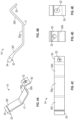
- FIG. 1 shows a mounting bracket assembly 10 incorporated into an unframed solar module supporting structure 3 comprising a module mounting rail 5.
- mounting bracket assembly 10 is an octagonal device that includes an upper clamp piece 12 comprised of a first member 16 and an upper partial fastener 18 and a lower clamp piece 14 comprised of a second member 17 that has a lower partial fastener 20.
- the upper partial fastener 18 may be a slot 32 and the lower partial fastener 20 may be a corresponding hinge part 34.
- An extra fastening and tightening mechanism may be provided such as a bolt and nut fastener 36 to cinch the upper and lower clamp pieces 12, 14 around the torque tube.
- the first member 16 of the upper clamp piece 12 has an open bottom space 24, best seen in FIGS. 3A and 3B .
- the open bottom space 24 may have a slight return 26 to facilitate the mounting bracket assembly 10 to be retained over a torque tube prior to installing the lower clamp piece 14. More particularly, slight return 26 serves the function of writing around two corners of the octagonal torque tube to effectively snap over the tube and stay on the tube prior to mounting the lower clamp piece 14 of the bracket assembly 10.
- the assembled mounting bracket assembly 10 defines a tube insertion aperture 22 suitable for a torque tube.
- the first member 16 of the upper clamp piece 12 is a component that constitutes the top five sides 30a-30e of the octagonally shaped mounting bracket assembly 10 with an open bottom space 24.
- the upper clamp piece 12 may have angled reinforcement features 28 to reinforce the mounting bracket.
- a first angled reinforcement feature 28a is formed at the top left octagonal side 30a of the upper clamp piece 12
- a second angled reinforcement feature 28b is formed at the top right octagonal side 30b of the upper clamp piece 12.
- the upper partial fastener 18 may be formed on either right or left octagonal sides 30d, 30e of the upper clamp piece.
- upper partial fastener 18 is a slot 32 formed at the bottom of the left octagonal side 30d of the upper clamp piece 12.
- a first flange 42 defining a first aperture 44 may be provided as part of a bolt and nut fastener assembly 36.
- the first flange 42 is formed on the bottom of the right octagonal side 30e of the upper clamp piece 12.
- the left octagonal side 30d of the upper clamp piece 12 may also have a first support fastener or slot 38a adjacent to the upper partial fastener 18.
- the first support fastener 38a provides an attachment mechanism so the mounting bracket assembly 10 can be attached to a mounting rail 5.
- a second support fastener 38b formed on the right octagonal side 30e of the upper clamp piece 12 allows attachment of one or more support rails 5 on the opposite side of mounting bracket assembly 10.
- two support rails 5 may be attached to each of the respective first and second support fasteners 38a, 38b to facilitate incorporation of the mounting bracket assembly 10 into a solar tracker or other mechanical system.
- the second member 17 of the lower clamp piece 14 is a component that constitutes the bottom three sides 30f, 30g, 30h of the octagonally shaped mounting bracket assembly 10.
- the lower clamp piece 14 has a lower partial fastener 20, which may be formed at the top end of the lower left octagonal side 30f.
- the lower partial fastener 20 is a hinge piece 34 that matingly corresponds to the slot 32, or upper partial fastener 18, of the upper clamp piece 12.
- hinge piece 34 can be clipped, snapped or slid into slot 32 to facilitate mounting of solar modules onto the torque tube of a solar tracker.
- a second flange 50 defining a second aperture 52 may be formed at the top end of the lower right octagonal side 30h.
- the second flange 50 mates with first flange 42 of the upper clamp piece 12 as part of the bolt and nut fastener assembly 36.
- the upper clamp piece 12 With reference to FIGS. 2A, 2B , and 8 , it can be seen that the upper clamp piece 12, with its five octagonal sides, together with the three octagonal sides of the lower clamp piece 14 form a full octagonal mounting bracket assembly.
- the lower partial fastener 20 of the lower clamp piece 14 mates with the upper partial fastener 18. More particularly, hinge piece 34 of the lower clamp piece 14 is slid, clipped, or snapped into slot 32 of the upper clamp piece 12.
- Exemplary mounting brackets 10 are designed so that when the lower clamp piece 14 attaches to the upper clamp piece 12 the open bottom space 24 is closed. In the assembled or closed configuration, as shown in FIGS. 5-8 , the mounting bracket assembly 10 comprising the attached upper and lower clamp pieces 12, 14 defines a tube insertion aperture 22 suitable for a torque tube.
- the upper clamp piece 12 and/or the lower clamp piece 14 of the mounting bracket assembly 10 also provide a conductive ground path to a torque tube. More particularly, the module mounting bracket assembly 10 may provide a conductive ground path to the torque tube without any extra components because it is made from conductive material such as aluminum.
- the mounting bracket assembly is fabricated from extruded aluminum, but it may also be fabricated from formed or cast metal, or possibly high strength plastic by way of injection molding or extrusion. If coatings are used on the aluminum, to retard corrosion for example, a metal ground clip or other electrically conductive grounding means may be incorporated to pierce through the coating in to create a reliable bonded conducting path.
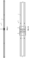
- exemplary embodiments of a mounting bracket assembly 110 will now be described. These embodiments differ from the mounting bracket assembly 10 described above in that the lower clamp piece 114 here is a long beam that has two opposing support members 150a, 150b which extend and attach to the mounting rail 7, taking the place of the separate support rails 5.
- the upper clamp piece 112 is similar to upper clamp piece 12 in that its first member 116 is a component that constitutes the top five sides 130a-130e of the octagonally shaped mounting bracket assembly 110 with an open bottom space 124.
- the open bottom space 124 may have a slight return to facilitate the mounting bracket assembly 110 to be retained over a torque tube prior to installing the lower clamp piece 114.
- the upper clamp piece 112 may have angled reinforcement features 128 to provide reinforcement to the mounting bracket.
- the upper clamp piece 112 has four reinforcement features 128 for attachment to the mounting rail 7 and additional support.
- First angled reinforcement feature 128a is formed at the top left octagonal side 130a
- a second angled reinforcement feature 128b is formed at the top right octagonal side 130b
- a third reinforcement feature 128c is formed at the left octagonal side 130d
- a fourth reinforcement feature is formed at the right octagonal side 130e.
- upper partial fastener 118b is formed in the fourth reinforcement feature 128d adjacent to the left octagonal side 130d of the upper clamp piece 112.
- upper partial fasteners 118a, 118b are part of a bolt and nut fastener assembly 136, and may be slide-on nuts.
- an exemplary embodiment of an upper clamp piece 112 has two reinforcement features 128c and 128d. More particularly, reinforcement feature 128c is formed at the left octagonal side 130d of the upper clamp piece 212, and reinforcement feature 128d is formed at the right octagonal side 130e. Without angled reinforcement features 128a and 128b, the upper clamp piece 212 and the top portions of the reinforcement features 128c and 128d provide attachment to mounting rail 7 and additional support, as best seen in FIGS. 16 and 18 . In the assembled or closed configuration, as shown in FIGS. 18 and 19 , the mounting bracket assembly 110 comprising the attached upper and lower clamp pieces 212, 114 defines a tube insertion aperture 122 suitable for a torque tube.
- the second member 117 of the lower clamp piece 114 is a component that comprises the bottom three sides 130f, 130g, 130h of the octagonally shaped mounting bracket assembly 110.
- the lower clamp piece 114 comprises two opposing support members 150a, 150b which extend and attach to the mounting rail 7 by one, two or more rivet studs or any other suitable fastener.
- the lower clamp piece 114 has two lower partial fasteners 120a and 120b, which may be bolts that mate with upper partial fasteners 118a and 118b, respectively, of the upper clamp piece 112, as part of two bolt and nut fastener assemblies 136a, 136b.
- lower partial fastener 120a is formed adjacent to the top end of the lower left octagonal side 130f
- upper partial fastener 120b is formed adjacent to the top end of the lower right octagonal side 130h.
- exemplary mounting bracket assemblies 10, 110 may be used with mounting rails for solar trackers mounting framed or frameless solar modules.
- a solar tracker assembly 1 includes a support column 2, a torque tube 4 connected to the support column, and one or more mounting rails 7 attached to the torque tube 4.
- An exemplary gear drive system 11 comprises a gear assembly 13 including at least one gear wheel 19.
- a motor (not shown) may be provided to drive the gear drive system 11, which in turn rotates the torsion tube 4, directly, or drives a gear rack 15, which in turn drives the torsion tube 4.
- the mounting rail 7 may be a support structure designed for unframed solar modules.
- the rail is a roll-formed steel module mounting rail and may be fabricated from roll formed steel and may be multiple meters in length.
- One or more solar modules 6 may be mounted to the mounting rail 7, and disclosed mounting bracket assemblies used to secure one more mounting rails to the torque tube 4.
- mounting clips 9 may be provided to facilitate mounting of the solar modules.
- the torque tube 4 of the solar tracker 1 may be any shape.
- the torque tube has an octagonal cross section.
- the torque tube cross section could be round or partially rounded, square, rectangular, pentagonal, hexagonal, D-shaped, or any other regular or irregular shape.
- embodiments of the mounting bracket assembly may be any shape corresponding to the torque tube cross section, such as round or partially rounded, square, rectangular, pentagonal, hexagonal, D-shaped, or any other regular or irregular shape.
- the open bottom space 24 of the module mounting bracket 10 may be designed to have a slight return 26 in order to snap over the vertical sides of an octagonal torque tube or a torque tube of another cross-sectional shape.
- methods of assembling a solar tracker including methods of attaching a mounting bracket assembly 10, 110 with or without support rails 5 to a torque tube 4.
- the open bottom space 24, 124 of the mounting bracket assembly 10, 110 allows the installer to attach module mounting rails 7 for unframed solar modules 6 onto the torque tube 4 anywhere along the length of the tube after it is installed in the field.
- the installer attaches a support rail 5 to the upper clamp piece 12 of the mounting bracket assembly 10. More particularly, the installer connects a first support rail 5 to the first support fastener or slot 38a on the left octagonal side 30d of the upper clamp piece 12.
- the installer may connect a second support rail 5 to the second support fastener 38b on the right octagonal side 30e of the upper clamp piece 12.
- the support rails 5 could be secured to the upper clamp piece 12 of the mounting bracket assembly 10 by any suitable fastening mechanism such as a bolt and nut fastener.
- the installer clips or snaps upper clamp piece 12 of the mounting bracket assembly 10 onto the torque tube 4. More particularly, the slight return of the open bottom space 24 allows the installer to clip or snap the upper clamp piece 12 of the mounting bracket assembly 10 over the vertical sides of the octagonal torque tube 4 to stay in position on the tube until full assembly is completed.
- the installer then attaches the lower clamp piece 14 of the mounting bracket assembly 10 to the upper clamp piece 12.
- the lower clamp piece 14 is attached to the upper clamp piece 12 by mating the lower partial fastener 20 of the lower clamp piece 14 with the upper partial fastener 18 of the upper clamp piece 12. More particularly, hinge piece 34 of the lower clamp piece 14 is slid or snapped into slot 32 of the upper clamp piece 12. This results in the open bottom space 24 being closed to form a tube insertion aperture 22 and the support rails 5 being secured to the torque tube 4.
- the bolt and nut fastener assembly 36 may then be tightened to cinch the mounting bracket assembly 10 around the torque tube 4 and further secure the support rails 5 to the toque tube 4. More particularly, the second flange 50 and second aperture 52 at the top end of the lower right octagonal side 30h of the lower clamp piece 14 is positioned to mate with first flange 42 and first aperture 44 of the upper clamp piece 12, the bolt inserted through the apertures 44, 52, and the nut tightened.
- the upper clamp piece 12 of the mounting bracket assembly 10 may have angled reinforcement features to provide reinforcement for the mounting bracket.
- the installer may secure the first angled reinforcement feature 28a at the top left octagonal side 30a of the upper clamp piece 12 and the second angled reinforcement feature 28b at the top right octagonal side 30b of the upper clamp piece 12 to the mounting rail 7 by any suitable fastening mechanism such as a bolt and nut fastener.
- the installer would install one or more solar modules on the mounting rail 7.
- the installer snaps upper clamp piece 112, 212 of the mounting bracket assembly 110 onto the torque tube 4. More particularly, the slight return of the open bottom space 124 allows the installer to snap the upper clamp piece 112, 212 of the mounting bracket assembly 110 over the vertical sides of the octagonal torque tube 4 to stay in position on the tube until full assembly is completed.
- the installer then attaches the lower clamp piece 114 of the mounting bracket assembly 110 to the upper clamp piece 112.
- the lower clamp piece 114 is attached to the upper clamp piece 112, 212 by connecting the lower partial fasteners 120a, 120b to the upper partial fasteners 118a, 118b using the slide-on bolt and nut fasteners or other suitable fastening mechanism.
- the installer secures the first angled reinforcement feature 128a at the top left octagonal side 130a of the upper clamp piece 112 and the second angled reinforcement feature 128b at the top right octagonal side 130b of the upper clamp piece 112 to the mounting rail 7 by any suitable fastening mechanism such as a bolt and nut fastener.
- the installer would also secure the lower clamp piece 114 to the mounting rail 7. More particularly, the two opposing support members 150a, 150b are connected to the mounting rail 7 by attaching the end of each respective support member 150a, 150b to the mounting rail 7 by one, two or more rivet studs or any other suitable fastener. In exemplary embodiments, the installer would install one or more solar modules on the mounting rail 7.
Landscapes
- Engineering & Computer Science (AREA)
- General Engineering & Computer Science (AREA)
- Mechanical Engineering (AREA)
- Life Sciences & Earth Sciences (AREA)
- Sustainable Development (AREA)
- Physics & Mathematics (AREA)
- Sustainable Energy (AREA)
- Combustion & Propulsion (AREA)
- Chemical & Material Sciences (AREA)
- Thermal Sciences (AREA)
- General Physics & Mathematics (AREA)
- Automation & Control Theory (AREA)
- Clamps And Clips (AREA)
- Connection Of Plates (AREA)
- Roof Covering Using Slabs Or Stiff Sheets (AREA)
- Joining Of Building Structures In Genera (AREA)
Claims (11)
- Ensemble de support de montage à huit côtés (10, 110, 210) pour fixer au moins un rail de montage (7) à un tube de torsion (4) dans un ensemble de suiveur solaire (1), l'ensemble de support de montage comprenant :une pièce de serrage supérieure (12, 112, 212) destinée à être fixée à l'au moins un rail de montage, la pièce de serrage supérieure ayant un premier élément (16, 116) et un espace inférieur ouvert (24, 124), la pièce de serrage supérieure comprenant une fixation partielle supérieure (18, 118a, 118b) ; etune pièce de serrage inférieure (14, 114) comportant un second élément (17, 117) avec une fixation partielle inférieure (20, 120a, 120b) configurée pour s'accoupler avec la fixation partielle supérieure de sorte que la pièce de serrage inférieure puisse être fixée à la pièce de serrage supérieure,dans lequelle premier élément comprend cinq côtés octogonaux (30a, 30b, 30c, 30d, 30e, 130a, 130b, 130c, 130d, 130e) et constitue les cinq côtés supérieurs (30a-30e) de l'ensemble de support de montage de forme octogonale,le second élément comprend trois côtés octogonaux (30f, 30g, 30h, 130f, 130g, 130h) et constitue les trois côtés inférieurs (30f, 30g, 30h) de l'ensemble de support de montage de forme octogonale (10),la fixation partielle supérieure (18, 118a, 118b) étant formée sur l'un des côtés octogonaux (30d ; 30e) de la pièce de serrage supérieure,la fixation partielle inférieure (20, 120a, 120b) étant formée à une extrémité supérieure de l'un des côtés octogonaux (30f) de la pièce de serrage inférieure (14, 114) qui correspond au côté octogonal de la pièce de serrage supérieure de la fixation partielle supérieure,dans lequel les fixations partielles supérieure et inférieure s'emboîtent de manière à former une charnière qui, lorsqu'elles sont fermées autour de la charnière, la pièce de serrage inférieure et la pièce de serrage supérieure définissent une ouverture d'insertion de tube (22, 122) adaptée pour retenir un tube de torsion.
- Ensemble de support de montage (10, 110, 210) selon la revendication 1 dans lequel le premier élément (16, 116) a un léger retour (26) de sorte que la pièce de serrage supérieure forme une fixation encliquetable sur un tube de torsion.
- Ensemble de support de montage (10, 110, 210) selon l'une quelconque des revendications 1 ou 2, dans lequel l'une de la pièce de serrage supérieure et de la pièce de serrage inférieure ou les deux fournissent un trajet de masse conducteur à un tube de torsion (4).
- Ensemble de support de montage (10, 110, 210) selon l'une quelconque des revendications 1 à 3, dans lequel la fixation partielle supérieure est une fente (32) et la fixation partielle inférieure est une pièce de charnière (34).
- Ensemble de support de montage (10, 110, 210) selon l'une quelconque des revendications 1 à 4 comprenant en outre au moins un élément de renforcement angulaire (28, 28a, 28b, 128, 128a, 128b) formé sur la pièce de serrage supérieure.
- Ensemble de support de montage (10, 110, 210) selon au moins la revendication 2, dans lequel le premier élément comporte deux légers retours, chaque léger retour se trouvant sur un côté opposé du premier élément.
- Ensemble de support de montage (110, 210) selon l'une quelconque des revendications 1 à 6, dans lequel la pièce de serrage inférieure comprend en outre deux éléments de support opposés (150a, 150b).
- Ensemble de support de montage (110, 210) selon la revendication 7 dans lequel les deux éléments de support opposés sont configurés pour se fixer au rail de montage (7).
- Ensemble de suiveur solaire (1) comprenant au moins un ensemble de support de montage (10, 110, 210) selon l'une quelconque des revendications précédentes et comprenant en outre :au moins une colonne de support (2) ;un tube de torsion (4) raccordé à la colonne de support ;au moins un rail de montage (7) fixé au tube de torsion ; etl'au moins un ensemble de support de montage fixant l'au moins un rail de montage au tube de torsion.
- Procédé de montage de modules solaires à l'aide d'au moins un ensemble de support de montage (10, 110, 210) selon l'une quelconque des revendications 1 à 8, comprenant :la fixation d'au moins un rail de montage (7) à la pièce de serrage supérieure (12, 112, 212) de l'au moins un ensemble de support de montage ;l'encliquetage de la pièce de serrage supérieure sur un tube de torsion (4) ; etla fixation de la pièce de serrage inférieure (14, 114) de l'au moins un ensemble de support de montage à la pièce de serrage supérieure en accouplant la fixation partielle inférieure (20, 120a, 120b) de la pièce de serrage inférieure à la fixation partielle supérieure (18, 118a, 118b) de sorte que l'espace inférieur ouvert (24, 124) soit fermé et que l'au moins un rail de montage soit fixé au tube de torsion.
- Procédé selon la revendication 10 comprenant en outre le serrage d'un boulon et d'un écrou (36, 136a, 136b) pour serrer les pièces de serrage supérieure et inférieure autour du tube de torsion.
Priority Applications (1)
| Application Number | Priority Date | Filing Date | Title |
|---|---|---|---|
| EP24197912.9A EP4446669A3 (fr) | 2016-06-12 | 2017-06-09 | Rails de montage clipsables, supports de montage, et procédés de montage de modules solaires |
Applications Claiming Priority (2)
| Application Number | Priority Date | Filing Date | Title |
|---|---|---|---|
| US201662348999P | 2016-06-12 | 2016-06-12 | |
| PCT/US2017/036710 WO2017218326A1 (fr) | 2016-06-12 | 2017-06-09 | Rails de montage clipsables, supports de montage, et procédés de montage de modules solaires |
Related Child Applications (1)
| Application Number | Title | Priority Date | Filing Date |
|---|---|---|---|
| EP24197912.9A Division EP4446669A3 (fr) | 2016-06-12 | 2017-06-09 | Rails de montage clipsables, supports de montage, et procédés de montage de modules solaires |
Publications (3)
| Publication Number | Publication Date |
|---|---|
| EP3469706A1 EP3469706A1 (fr) | 2019-04-17 |
| EP3469706A4 EP3469706A4 (fr) | 2019-11-27 |
| EP3469706B1 true EP3469706B1 (fr) | 2024-09-04 |
Family
ID=60574269
Family Applications (2)
| Application Number | Title | Priority Date | Filing Date |
|---|---|---|---|
| EP17813834.3A Active EP3469706B1 (fr) | 2016-06-12 | 2017-06-09 | Rails de montage clipsables, supports de montage, et procédés de montage de modules solaires |
| EP24197912.9A Withdrawn EP4446669A3 (fr) | 2016-06-12 | 2017-06-09 | Rails de montage clipsables, supports de montage, et procédés de montage de modules solaires |
Family Applications After (1)
| Application Number | Title | Priority Date | Filing Date |
|---|---|---|---|
| EP24197912.9A Withdrawn EP4446669A3 (fr) | 2016-06-12 | 2017-06-09 | Rails de montage clipsables, supports de montage, et procédés de montage de modules solaires |
Country Status (11)
| Country | Link |
|---|---|
| US (3) | US10536109B2 (fr) |
| EP (2) | EP3469706B1 (fr) |
| JP (1) | JP6983820B2 (fr) |
| KR (1) | KR102341671B1 (fr) |
| CN (1) | CN109743890B (fr) |
| AU (1) | AU2017284105B2 (fr) |
| BR (1) | BR112018075675B1 (fr) |
| ES (1) | ES2998545T3 (fr) |
| MX (1) | MX2018015432A (fr) |
| PT (1) | PT3469706T (fr) |
| WO (1) | WO2017218326A1 (fr) |
Cited By (1)
| Publication number | Priority date | Publication date | Assignee | Title |
|---|---|---|---|---|
| US20250125766A1 (en) * | 2023-10-16 | 2025-04-17 | Maxeon Solar Pte. Ltd. | Frameless, backrail-supported solar module and installation methods |
Families Citing this family (67)
| Publication number | Priority date | Publication date | Assignee | Title |
|---|---|---|---|---|
| CN106062489B (zh) | 2014-02-19 | 2019-04-26 | 阵列技术公司 | 扭矩限制器设备、系统和方法以及包含扭矩限制器的太阳能跟踪器 |
| KR102401773B1 (ko) | 2016-03-24 | 2022-05-25 | 아치 엔터프라이즈 인코포레이티드 | 모듈형 유틸리티 시스템 |
| US12565962B2 (en) | 2016-03-24 | 2026-03-03 | Archi Enterprises Inc. | Modular utility system |
| EP3469706B1 (fr) * | 2016-06-12 | 2024-09-04 | Array Technologies, Inc. | Rails de montage clipsables, supports de montage, et procédés de montage de modules solaires |
| US11283395B2 (en) | 2018-03-23 | 2022-03-22 | Nextracker Inc. | Multiple actuator system for solar tracker |
| US11387771B2 (en) | 2018-06-07 | 2022-07-12 | Nextracker Llc | Helical actuator system for solar tracker |
| US10797635B2 (en) * | 2018-08-29 | 2020-10-06 | Nextracker Inc. | Solar module mounting bracket assemblies |
| US10845092B2 (en) * | 2018-09-19 | 2020-11-24 | Robert B. Dally | Panel mounting components |
| US11271518B2 (en) * | 2018-11-08 | 2022-03-08 | OMCO Solar, LLC | Mounting bracket for mounting photovoltaic modules to torque tube beam |
| CN109782811B (zh) * | 2019-02-02 | 2021-10-08 | 绥化学院 | 一种无人模型车的自动跟随控制系统及方法 |
| DE102019112201A1 (de) * | 2019-05-09 | 2020-11-12 | Robert Zimmermann | Solarmodulhaltevorrichtung und Verfahren zur Herstellung einer Solarmodulhaltevorrichtung |
| US11050383B2 (en) | 2019-05-21 | 2021-06-29 | Nextracker Inc | Radial cam helix with 0 degree stow for solar tracker |
| US11588434B2 (en) | 2019-06-18 | 2023-02-21 | Nextracker Llc | Expandable splice for a solar power system |
| AU2021428570A1 (en) * | 2019-08-12 | 2023-08-17 | Rosendin Electric, Inc. | A bracket usable for solar panel module installation |
| US11500397B2 (en) | 2019-10-02 | 2022-11-15 | Array Technologies, Inc. | Solar tracking during persistent cloudy conditions |
| PT3828480T (pt) * | 2019-11-29 | 2023-08-21 | Soltec Innovations Sl | Sistema de fixação para fixação de um revestimento a um tubo |
| USD940547S1 (en) | 2019-12-13 | 2022-01-11 | Array Technologies, Inc. | Clamp |
| US12031750B2 (en) | 2019-12-13 | 2024-07-09 | Array Tech, Inc. | Modified clamp |
| ES1243445Y (es) * | 2019-12-18 | 2020-08-28 | Soltec Innovations Sl | Bastidor autoportante para paneles fotovoltaicos |
| US11569780B2 (en) * | 2020-03-17 | 2023-01-31 | Sun And Steel Solar Llc | Purlin system for solar module attachment |
| DE102020107794A1 (de) | 2020-03-20 | 2021-09-23 | Sbp Sonne Gmbh | Vorrichtung zum Verriegeln einer Nachführeinrichtung für eine PV-Anlage und Verfahren zum Entriegeln einer Nachführeinrichtung |
| DE102020107793A1 (de) | 2020-03-20 | 2021-09-23 | Sbp Sonne Gmbh | Nachführeinrichtung für eine PV-Anlage (Zentralrohr und Tragstruktur für PV-Module) |
| ES1248271Y (es) * | 2020-05-07 | 2020-09-14 | Manonelles Montserrat Bonjoch | Soporte de modulos fotovoltaicos |
| US20230223892A1 (en) * | 2020-05-07 | 2023-07-13 | Montserrat Bonjoch Manonelles | Support for photovoltaic modules |
| USD956537S1 (en) | 2020-05-08 | 2022-07-05 | Array Technologies, Inc. | Mounting hardware |
| CN115769487A (zh) * | 2020-05-08 | 2023-03-07 | 阵列科技股份有限公司 | 安装支架 |
| USD956536S1 (en) | 2020-05-08 | 2022-07-05 | Array Technologies, Inc. | Mounting hardware |
| USD956538S1 (en) | 2020-05-08 | 2022-07-05 | Array Technologies, Inc. | Mounting hardware |
| US11527988B2 (en) * | 2020-05-13 | 2022-12-13 | Array Technologies, Inc. | Mounting bracket extension |
| CN111720677A (zh) * | 2020-06-18 | 2020-09-29 | 泰州市金海运船用设备有限责任公司 | 海洋油污渗漏轨迹追踪辅助系统 |
| EP4197099A4 (fr) * | 2020-08-17 | 2024-12-25 | Nextracker LLC | Liaison de plusieurs parois sur des piliers |
| CN116250174A (zh) * | 2020-10-05 | 2023-06-09 | 耐克斯特拉克尔有限责任公司 | D形扭矩管及轴承组合件 |
| CN112187156A (zh) * | 2020-10-27 | 2021-01-05 | 宁波市路棠电子科技有限公司 | 一种高效智能追踪太阳能充电设备 |
| USD987421S1 (en) * | 2020-12-11 | 2023-05-30 | Array Technologies, Inc. | Clamp |
| AU2021401315A1 (en) * | 2020-12-18 | 2023-07-06 | Preformed Line Products Co. | Photovoltaic panel cable mount arrangement |
| CN112878429A (zh) * | 2021-01-20 | 2021-06-01 | 河北洪春专用车制造有限公司 | 一种吸附式低湿空气取水装置 |
| CN114928320A (zh) * | 2021-02-11 | 2022-08-19 | 加拿大太阳能(美国)有限公司 | 太阳能电池板支架系统 |
| US11962269B2 (en) | 2021-02-24 | 2024-04-16 | Array Technologies, Inc. | Low-profile backrail module clamp |
| WO2022183204A1 (fr) * | 2021-02-24 | 2022-09-01 | Array Technologies, Inc. | Système de montage de module photovoltaïque à verrouillage par pression |
| WO2022192910A1 (fr) | 2021-03-11 | 2022-09-15 | Array Technologies, Inc. | Rangement de modules photovoltaïques pour atténuation de grêle |
| US11817814B2 (en) * | 2021-04-28 | 2023-11-14 | James E. Straeter | Ground mounted solar power assembly |
| CN117836571A (zh) * | 2021-07-08 | 2024-04-05 | 耐克斯特拉克尔有限责任公司 | 太阳能模块夹具 |
| AU2022378624A1 (en) | 2021-10-27 | 2024-05-16 | Nextpower Llc | Fastening assembly for solar power systems and tools thereof |
| CN219178009U (zh) * | 2021-10-28 | 2023-06-13 | 上海施步新能源科技有限公司 | 具有阻尼机构的太阳能支架 |
| WO2023107711A1 (fr) * | 2021-12-09 | 2023-06-15 | National Oilwell Varco, L.P. | Supports de montage et procédés associés pour fixer des modules solaires de réseaux solaires |
| US11984842B2 (en) * | 2022-05-09 | 2024-05-14 | FTC Solar, Inc. | Solar tracker systems and methods including a rail assembly |
| US20240283392A1 (en) * | 2022-05-09 | 2024-08-22 | FTC Solar, Inc. | Solar tracker systems and methods including a rail assembly |
| WO2023235521A1 (fr) * | 2022-06-01 | 2023-12-07 | Array Technologies, Inc. | Pince de module de rail arrière à profil bas |
| WO2024011313A1 (fr) * | 2022-07-11 | 2024-01-18 | Archi Enterprises Inc. | Système d'accessoires modulaire |
| US12074559B2 (en) | 2022-08-01 | 2024-08-27 | Array Tech, Inc. | Photovoltaic module mount |
| US20240072721A1 (en) * | 2022-08-24 | 2024-02-29 | Nextracker Llc | Solar module rail couplings for solar tracker |
| US11848638B1 (en) * | 2022-08-27 | 2023-12-19 | Sunmodo Corporation | Device and system for mounting solar panels to metal roofs |
| USD1068460S1 (en) | 2022-11-11 | 2025-04-01 | L&Bsolutions, Llc | Bracket |
| US20240235470A1 (en) | 2023-01-09 | 2024-07-11 | Sarcos Corp. | Auto-Engaging Electrical Connections for Solar Panels |
| CN120530289A (zh) * | 2023-01-17 | 2025-08-22 | 亚雷科技有限公司 | 太阳能跟踪系统支撑装置 |
| US12123627B2 (en) | 2023-01-17 | 2024-10-22 | Array Tech, Inc. | Solar tracking system support devices |
| US12476579B2 (en) | 2023-03-20 | 2025-11-18 | Nextracker Llc | Solar module rail couplings for solar tracker |
| US12466066B2 (en) | 2023-05-04 | 2025-11-11 | Sarcos Corp. | Solar panel dispensing device with vertical solar panel hopper loading and dispensing |
| US12573978B2 (en) * | 2023-07-10 | 2026-03-10 | Array Tech, Inc. | Mounting rails |
| US20250027873A1 (en) * | 2023-07-20 | 2025-01-23 | Matergenics, Inc. | Atmospheric corrosivity monitoring system |
| US12486862B2 (en) | 2023-08-21 | 2025-12-02 | Nextracker Llc | Solar module washer clip |
| US20250080040A1 (en) * | 2023-09-05 | 2025-03-06 | Flexrack By Qcells Llc | Module mounting system for a solar structure |
| US20250177224A1 (en) * | 2023-11-30 | 2025-06-05 | Hill-Rom Services, Inc. | Patient helper handle self-locking clamp |
| US12542513B2 (en) | 2024-01-08 | 2026-02-03 | Sarcos Corp. | Torque tube clamps for automated solar panel installation |
| US20250224148A1 (en) * | 2024-01-08 | 2025-07-10 | Sarcos Corp. | Solar Panel Installation Alignment Systems |
| US12570001B2 (en) | 2024-01-08 | 2026-03-10 | Sarcos Corp. | Support clamp installation vehicles as part of a solar panel installation system for a solar tracking system |
| JP2025117179A (ja) * | 2024-01-30 | 2025-08-12 | 景欣股▲分▼有限公司 | ソーラーパネル用ブラケット |
Family Cites Families (74)
| Publication number | Priority date | Publication date | Assignee | Title |
|---|---|---|---|---|
| US704957A (en) | 1902-03-15 | 1902-07-15 | William F Kean | Bracket for subsidiary shelving. |
| US1053610A (en) | 1911-07-28 | 1913-02-18 | Arthur James Kelly | Perpetual calendar. |
| US1831641A (en) | 1927-07-20 | 1931-11-10 | M B Skinner Co | Pipe clamp |
| US1832315A (en) | 1930-10-25 | 1931-11-17 | Mcnulty Alexis Copp | Supporting device |
| FR880114A (fr) | 1941-03-12 | 1943-03-15 | Support d'écartement, en deux parties, pour canalisations pour endroits humides | |
| US2675201A (en) | 1948-09-22 | 1954-04-13 | Friel Patrick | Beam attachment clamp |
| US3026368A (en) | 1959-03-10 | 1962-03-20 | L E Lindsey | Conductor clamp assembly for use on pole top insulators |
| US3698691A (en) | 1971-06-16 | 1972-10-17 | Thomas W Brown | Fence barb arm |
| US4019705A (en) | 1972-04-05 | 1977-04-26 | Habuda Sr Blair A | Pipe hanging apparatus |
| JPS5436314Y2 (fr) * | 1975-05-06 | 1979-11-02 | ||
| US4065218A (en) | 1976-11-10 | 1977-12-27 | Super Strut, Inc. | Seismic brace |
| US4089276A (en) | 1977-04-08 | 1978-05-16 | Enos Ernest S | Portable bumper platform |
| US4131257A (en) | 1977-11-14 | 1978-12-26 | Eby Company | Stacking cable clamp |
| US4371139A (en) | 1979-12-31 | 1983-02-01 | Sunsearch, Inc. | Adjustable mounting rack for solar collectors |
| DE8520407U1 (de) | 1985-07-15 | 1985-09-26 | Siemens AG, 1000 Berlin und 8000 München | Haltevorrichtung für eine Anzahl von Paneelen, die mit Solarzellen bestückt sind |
| IT222671Z2 (it) | 1991-07-05 | 1995-04-24 | Tassalini Flli | Reggitubo |
| US5494245A (en) * | 1994-05-04 | 1996-02-27 | Yazaki Corporation | Wiring harness retainer clip |
| CN2206637Y (zh) | 1994-08-02 | 1995-09-06 | 朱同森 | 支架夹头 |
| US5863020A (en) | 1995-11-01 | 1999-01-26 | Rose Manufacturing Company | Lifeline mounting apparatus |
| US5757567A (en) | 1996-02-08 | 1998-05-26 | International Business Machines Corporation | Method and apparatus for servo control with high efficiency gray code for servo track ID |
| US6431502B1 (en) | 2000-03-11 | 2002-08-13 | All-Points Equipment Co., L.P. | Cable clamp |
| DE10025538A1 (de) | 2000-05-23 | 2001-11-29 | Walter Juergens | Solarmontagestein |
| US20040092142A1 (en) | 2002-11-07 | 2004-05-13 | Consolidated Manufacturing International, Llc | Clamping apparatus for connecting ground wire to grounding member |
| US6896301B2 (en) | 2002-11-12 | 2005-05-24 | Master Pneumatic-Detroit, Inc. | Clamp assembly |
| DE20319065U1 (de) | 2003-12-09 | 2004-02-26 | Phönix SonnenStrom AG | Solaranordnung mit einer Tragkonstruktion für ein oder mehrere Solarmodule |
| EP1566586A1 (fr) | 2004-02-20 | 2005-08-24 | Federnfabrik+Apparatebau Kaltbrunn AG | Collier de serrage pour tuyaux |
| US7284728B2 (en) | 2004-12-29 | 2007-10-23 | Connolly Michael J | Pipe hanger assembly |
| JP2007132579A (ja) | 2005-11-09 | 2007-05-31 | Max Co Ltd | 管路構造、給湯システム及び室 |
| US7472876B2 (en) | 2006-07-21 | 2009-01-06 | Jones Thomas M | Bracket system |
| DE102007001827A1 (de) | 2007-01-12 | 2008-07-17 | Hermann Posselt | Vorrichtung aus einer Mehrzahl von Tragwerksmodulen |
| NZ576948A (en) * | 2007-01-22 | 2010-12-24 | Allexcel Inc | Self-assembling amphiphilic polymers as antiviral agents |
| JP5013263B2 (ja) | 2007-10-26 | 2012-08-29 | 株式会社ダイフク | 棒状部材に対する部材取付け構造 |
| US7784745B2 (en) * | 2008-06-02 | 2010-08-31 | Robert Dodge | Tube clip |
| US8413391B2 (en) | 2008-10-13 | 2013-04-09 | Sunlink Corporation | Solar array mounting system with universal clamp |
| US8413944B2 (en) | 2009-05-01 | 2013-04-09 | Applied Energy Technologies | Mounting systems for solar panels |
| KR101403129B1 (ko) * | 2009-05-07 | 2014-06-05 | 오쏠라 유한회사 | 태양광 추종이 가능한 태양광 발전 장치 |
| AU2010317684A1 (en) | 2009-09-25 | 2012-04-12 | Waterco Limited | Modular thermal water solar panel system |
| FR2951254B1 (fr) | 2009-10-13 | 2013-10-04 | Claude Jacquot | Dispositif pour fixer un panneau solaire a une structure porteuse ayant des longerons |
| US20110253190A1 (en) | 2010-04-15 | 2011-10-20 | Daetwyler-Clean Energy LLC | Solar panel mounting bracket and solar panel mounting system |
| KR100997883B1 (ko) * | 2010-04-19 | 2010-12-02 | 주식회사 유일엔시스 | 토크튜브 지지체 및 이를 이용한 태양광 트랙커 |
| GB201009963D0 (en) | 2010-06-15 | 2010-07-21 | Airbus Operations Ltd | Modular conduit retntion system |
| CA2802759A1 (fr) | 2010-06-24 | 2011-12-29 | Magna International Inc. | Ensemble support solaire modulaire |
| FR2972574A1 (fr) | 2011-03-11 | 2012-09-14 | Mobasolar | Procede de mise a la terre d'une installation electrique et dispositif de connexion pour la mise en oeuvre dudit procede |
| US8572909B2 (en) | 2011-03-24 | 2013-11-05 | Solar Mounting Solutions, LLC | Flat roof solar racking system |
| US8776454B2 (en) * | 2011-04-05 | 2014-07-15 | Michael Zuritis | Solar array support structure, mounting rail and method of installation thereof |
| US8939143B2 (en) * | 2011-05-09 | 2015-01-27 | Michael Zuritis | Solar array column cap |
| CA2832379A1 (fr) | 2011-05-24 | 2012-11-29 | Magna International Inc. | Ensemble cadre de support et procede permettant de former un ensemble cadre de support |
| DE102011106083A1 (de) | 2011-06-08 | 2012-12-13 | Schletter Gmbh | Ständer für PV-Module |
| EP3009766B1 (fr) * | 2011-08-12 | 2017-10-04 | First Solar, Inc | Système de poursuite solaire |
| US20130118627A1 (en) | 2011-11-14 | 2013-05-16 | United Technologies Corporation | Tuned response duct clamp |
| US9035168B2 (en) | 2011-12-21 | 2015-05-19 | Sunpower Corporation | Support for solar energy collectors |
| US8713881B2 (en) | 2012-01-27 | 2014-05-06 | A. Raymond Et Cie | Solar panel securing system |
| WO2013119555A2 (fr) | 2012-02-06 | 2013-08-15 | First Solar, Inc. | Pince de fixation et configuration de pince de fixation pour installation de module photovoltaïque |
| US20140076379A1 (en) | 2012-09-14 | 2014-03-20 | Cogenra Solar | Concentrating solar energy collector |
| US9322437B2 (en) * | 2012-12-28 | 2016-04-26 | Sunpower Corporation | Support for solar energy collection |
| US9347691B2 (en) * | 2013-02-26 | 2016-05-24 | Solarcity Corporation | Torque Tube Mounted Photovoltaic Apparatus, System, and Method |
| AU2014236707B2 (en) * | 2013-03-15 | 2017-10-19 | Sunpower Corporation | Support for solar energy collection |
| US20140290716A1 (en) | 2013-03-29 | 2014-10-02 | Unirac, Inc. | Photovoltaic module mounting assembly |
| US9551508B2 (en) * | 2013-06-24 | 2017-01-24 | James E. Straeter | Ground mounted solar power assembly |
| US9206999B2 (en) * | 2013-08-29 | 2015-12-08 | JSI Equipment Solutions LLC | Bearing for solar panel tracking system |
| US20150059827A1 (en) * | 2013-08-29 | 2015-03-05 | JSI Equipment Solutions LLC | Torque Tube for Solar Panel System |
| US10069455B2 (en) | 2013-10-02 | 2018-09-04 | Array Technologies, Inc. | Mounting bracket assemblies and methods |
| US9281778B2 (en) * | 2013-10-02 | 2016-03-08 | Array Technologies, Inc. | Mounting bracket assemblies and methods |
| US9276521B2 (en) * | 2014-01-16 | 2016-03-01 | JSI Equipment Solutions LLC | Clamp for solar panel array |
| CN106062489B (zh) * | 2014-02-19 | 2019-04-26 | 阵列技术公司 | 扭矩限制器设备、系统和方法以及包含扭矩限制器的太阳能跟踪器 |
| WO2016073343A1 (fr) * | 2014-11-03 | 2016-05-12 | First Solar, Inc. | Dispositif de montage de module photovoltaïque |
| US9793852B2 (en) * | 2015-07-15 | 2017-10-17 | Solarcity Corporation | Clamp and bowl mounting system for photovoltaic modules |
| US10720877B2 (en) * | 2016-02-25 | 2020-07-21 | Solarcity Corporation | Photovoltaic mounting system for solar tracker array |
| US10622937B2 (en) | 2016-04-06 | 2020-04-14 | Solarcity Corporation | Spring latch saddle connector for solar tracker |
| US10469024B2 (en) * | 2016-04-08 | 2019-11-05 | Solarcity Corporation | Pre-assembled nesting photovoltaic module bracket for solar tracker |
| US10587216B2 (en) * | 2016-04-20 | 2020-03-10 | Solarcity Corporation | Over-center under photovoltaic module clamp |
| EP3469706B1 (fr) * | 2016-06-12 | 2024-09-04 | Array Technologies, Inc. | Rails de montage clipsables, supports de montage, et procédés de montage de modules solaires |
| CN120444759A (zh) * | 2017-03-02 | 2025-08-08 | 阵列科技股份有限公司 | 弹簧平衡组件和包括弹簧平衡组件的太阳能跟踪器 |
| US20190158017A1 (en) * | 2017-08-31 | 2019-05-23 | QuantPower, Inc. | Tracker System with Bridge |
-
2017
- 2017-06-09 EP EP17813834.3A patent/EP3469706B1/fr active Active
- 2017-06-09 BR BR112018075675-0A patent/BR112018075675B1/pt active IP Right Grant
- 2017-06-09 JP JP2018564787A patent/JP6983820B2/ja active Active
- 2017-06-09 KR KR1020187038180A patent/KR102341671B1/ko active Active
- 2017-06-09 AU AU2017284105A patent/AU2017284105B2/en active Active
- 2017-06-09 ES ES17813834T patent/ES2998545T3/es active Active
- 2017-06-09 WO PCT/US2017/036710 patent/WO2017218326A1/fr not_active Ceased
- 2017-06-09 EP EP24197912.9A patent/EP4446669A3/fr not_active Withdrawn
- 2017-06-09 MX MX2018015432A patent/MX2018015432A/es unknown
- 2017-06-09 US US15/618,408 patent/US10536109B2/en active Active
- 2017-06-09 PT PT178138343T patent/PT3469706T/pt unknown
- 2017-06-09 CN CN201780048409.2A patent/CN109743890B/zh active Active
-
2020
- 2020-01-13 US US16/741,597 patent/US10917039B2/en active Active
-
2021
- 2021-02-08 US US17/170,820 patent/US11563402B2/en active Active
Cited By (1)
| Publication number | Priority date | Publication date | Assignee | Title |
|---|---|---|---|---|
| US20250125766A1 (en) * | 2023-10-16 | 2025-04-17 | Maxeon Solar Pte. Ltd. | Frameless, backrail-supported solar module and installation methods |
Also Published As
| Publication number | Publication date |
|---|---|
| US20170359017A1 (en) | 2017-12-14 |
| PT3469706T (pt) | 2024-12-05 |
| EP3469706A4 (fr) | 2019-11-27 |
| AU2017284105B2 (en) | 2021-08-05 |
| US20210159849A1 (en) | 2021-05-27 |
| MX2018015432A (es) | 2019-04-11 |
| BR112018075675A2 (pt) | 2019-04-02 |
| EP3469706A1 (fr) | 2019-04-17 |
| KR20190018450A (ko) | 2019-02-22 |
| EP4446669A2 (fr) | 2024-10-16 |
| US11563402B2 (en) | 2023-01-24 |
| WO2017218326A1 (fr) | 2017-12-21 |
| AU2017284105A1 (en) | 2019-01-03 |
| ES2998545T3 (en) | 2025-02-20 |
| US20200162016A1 (en) | 2020-05-21 |
| BR112018075675B1 (pt) | 2023-11-28 |
| JP2019521634A (ja) | 2019-07-25 |
| CN109743890A (zh) | 2019-05-10 |
| CN109743890B (zh) | 2021-01-15 |
| US10536109B2 (en) | 2020-01-14 |
| US10917039B2 (en) | 2021-02-09 |
| KR102341671B1 (ko) | 2021-12-20 |
| EP4446669A3 (fr) | 2025-01-15 |
| JP6983820B2 (ja) | 2021-12-17 |
Similar Documents
| Publication | Publication Date | Title |
|---|---|---|
| EP3469706B1 (fr) | Rails de montage clipsables, supports de montage, et procédés de montage de modules solaires | |
| US12587126B2 (en) | Snap-in mounting systems for laminate solar panels | |
| CN112105874B (zh) | 太阳能模块安装系统 | |
| US9057542B2 (en) | Snap-on structural connector | |
| US9263985B2 (en) | Rooftop photovoltaic modules | |
| US20140202525A1 (en) | Solar module mounting bracket and assemblies | |
| US20110163209A1 (en) | Mounting clips and sensor installations for motorized vehicle doors | |
| US20210102577A1 (en) | Rail mounting apparatus, system and method of securing devices to a structure | |
| US20190036474A1 (en) | Click-On Tower and L-Foot Mount for Attaching Solar Panels to a Roof | |
| US20150069888A1 (en) | Electronic equipment cabinet structure | |
| US20100180933A1 (en) | Grounding system and method for use with solar panel modules | |
| US20110162279A1 (en) | Sensor installations for motorized vehicle doors | |
| US12255574B2 (en) | Photovoltaic module accessory clamp | |
| HU222392B1 (hu) | Derékszögû, paralelepipedon alakú fém tartókeret, különösen elektromos szekrényekhez való tartókeret | |
| US20130037087A1 (en) | Integrated Solar Module | |
| US9157619B1 (en) | Reversible pole or wall mounting bracket | |
| EP2186972A2 (fr) | Système de cloison de sécurité et clip universel pour un tel système | |
| US20060198715A1 (en) | Fastener receptacle | |
| US10581375B2 (en) | Mounting clip for structure having spaced apart trim | |
| US12328095B2 (en) | Alignment bracket | |
| CN211032387U (zh) | 一种行李架安装结构及车辆 |
Legal Events
| Date | Code | Title | Description |
|---|---|---|---|
| STAA | Information on the status of an ep patent application or granted ep patent |
Free format text: STATUS: THE INTERNATIONAL PUBLICATION HAS BEEN MADE |
|
| PUAI | Public reference made under article 153(3) epc to a published international application that has entered the european phase |
Free format text: ORIGINAL CODE: 0009012 |
|
| STAA | Information on the status of an ep patent application or granted ep patent |
Free format text: STATUS: REQUEST FOR EXAMINATION WAS MADE |
|
| 17P | Request for examination filed |
Effective date: 20190104 |
|
| AK | Designated contracting states |
Kind code of ref document: A1 Designated state(s): AL AT BE BG CH CY CZ DE DK EE ES FI FR GB GR HR HU IE IS IT LI LT LU LV MC MK MT NL NO PL PT RO RS SE SI SK SM TR |
|
| AX | Request for extension of the european patent |
Extension state: BA ME |
|
| DAV | Request for validation of the european patent (deleted) | ||
| DAX | Request for extension of the european patent (deleted) | ||
| A4 | Supplementary search report drawn up and despatched |
Effective date: 20191028 |
|
| RIC1 | Information provided on ipc code assigned before grant |
Ipc: H02S 20/32 20140101AFI20191022BHEP Ipc: F24S 30/425 20180101ALI20191022BHEP |
|
| STAA | Information on the status of an ep patent application or granted ep patent |
Free format text: STATUS: EXAMINATION IS IN PROGRESS |
|
| 17Q | First examination report despatched |
Effective date: 20220401 |
|
| P01 | Opt-out of the competence of the unified patent court (upc) registered |
Effective date: 20230516 |
|
| GRAP | Despatch of communication of intention to grant a patent |
Free format text: ORIGINAL CODE: EPIDOSNIGR1 |
|
| STAA | Information on the status of an ep patent application or granted ep patent |
Free format text: STATUS: GRANT OF PATENT IS INTENDED |
|
| INTG | Intention to grant announced |
Effective date: 20240103 |
|
| GRAJ | Information related to disapproval of communication of intention to grant by the applicant or resumption of examination proceedings by the epo deleted |
Free format text: ORIGINAL CODE: EPIDOSDIGR1 |
|
| STAA | Information on the status of an ep patent application or granted ep patent |
Free format text: STATUS: EXAMINATION IS IN PROGRESS |
|
| GRAP | Despatch of communication of intention to grant a patent |
Free format text: ORIGINAL CODE: EPIDOSNIGR1 |
|
| STAA | Information on the status of an ep patent application or granted ep patent |
Free format text: STATUS: GRANT OF PATENT IS INTENDED |
|
| INTC | Intention to grant announced (deleted) | ||
| INTG | Intention to grant announced |
Effective date: 20240422 |
|
| GRAS | Grant fee paid |
Free format text: ORIGINAL CODE: EPIDOSNIGR3 |
|
| GRAA | (expected) grant |
Free format text: ORIGINAL CODE: 0009210 |
|
| STAA | Information on the status of an ep patent application or granted ep patent |
Free format text: STATUS: THE PATENT HAS BEEN GRANTED |
|
| AK | Designated contracting states |
Kind code of ref document: B1 Designated state(s): AL AT BE BG CH CY CZ DE DK EE ES FI FR GB GR HR HU IE IS IT LI LT LU LV MC MK MT NL NO PL PT RO RS SE SI SK SM TR |
|
| REG | Reference to a national code |
Ref country code: GB Ref legal event code: FG4D |
|
| REG | Reference to a national code |
Ref country code: CH Ref legal event code: EP |
|
| REG | Reference to a national code |
Ref country code: IE Ref legal event code: FG4D |
|
| REG | Reference to a national code |
Ref country code: DE Ref legal event code: R096 Ref document number: 602017084675 Country of ref document: DE |
|
| REG | Reference to a national code |
Ref country code: PT Ref legal event code: SC4A Ref document number: 3469706 Country of ref document: PT Date of ref document: 20241205 Kind code of ref document: T Free format text: AVAILABILITY OF NATIONAL TRANSLATION Effective date: 20241129 |
|
| REG | Reference to a national code |
Ref country code: LT Ref legal event code: MG9D |
|
| REG | Reference to a national code |
Ref country code: NL Ref legal event code: MP Effective date: 20240904 |
|
| PG25 | Lapsed in a contracting state [announced via postgrant information from national office to epo] |
Ref country code: NO Free format text: LAPSE BECAUSE OF FAILURE TO SUBMIT A TRANSLATION OF THE DESCRIPTION OR TO PAY THE FEE WITHIN THE PRESCRIBED TIME-LIMIT Effective date: 20241204 |
|
| PG25 | Lapsed in a contracting state [announced via postgrant information from national office to epo] |
Ref country code: PL Free format text: LAPSE BECAUSE OF FAILURE TO SUBMIT A TRANSLATION OF THE DESCRIPTION OR TO PAY THE FEE WITHIN THE PRESCRIBED TIME-LIMIT Effective date: 20240904 Ref country code: GR Free format text: LAPSE BECAUSE OF FAILURE TO SUBMIT A TRANSLATION OF THE DESCRIPTION OR TO PAY THE FEE WITHIN THE PRESCRIBED TIME-LIMIT Effective date: 20241205 Ref country code: FI Free format text: LAPSE BECAUSE OF FAILURE TO SUBMIT A TRANSLATION OF THE DESCRIPTION OR TO PAY THE FEE WITHIN THE PRESCRIBED TIME-LIMIT Effective date: 20240904 |
|
| PG25 | Lapsed in a contracting state [announced via postgrant information from national office to epo] |
Ref country code: BG Free format text: LAPSE BECAUSE OF FAILURE TO SUBMIT A TRANSLATION OF THE DESCRIPTION OR TO PAY THE FEE WITHIN THE PRESCRIBED TIME-LIMIT Effective date: 20240904 |
|
| PG25 | Lapsed in a contracting state [announced via postgrant information from national office to epo] |
Ref country code: LV Free format text: LAPSE BECAUSE OF FAILURE TO SUBMIT A TRANSLATION OF THE DESCRIPTION OR TO PAY THE FEE WITHIN THE PRESCRIBED TIME-LIMIT Effective date: 20240904 |
|
| PG25 | Lapsed in a contracting state [announced via postgrant information from national office to epo] |
Ref country code: HR Free format text: LAPSE BECAUSE OF FAILURE TO SUBMIT A TRANSLATION OF THE DESCRIPTION OR TO PAY THE FEE WITHIN THE PRESCRIBED TIME-LIMIT Effective date: 20240904 |
|
| PG25 | Lapsed in a contracting state [announced via postgrant information from national office to epo] |
Ref country code: RS Free format text: LAPSE BECAUSE OF FAILURE TO SUBMIT A TRANSLATION OF THE DESCRIPTION OR TO PAY THE FEE WITHIN THE PRESCRIBED TIME-LIMIT Effective date: 20241204 |
|
| PG25 | Lapsed in a contracting state [announced via postgrant information from national office to epo] |
Ref country code: RS Free format text: LAPSE BECAUSE OF FAILURE TO SUBMIT A TRANSLATION OF THE DESCRIPTION OR TO PAY THE FEE WITHIN THE PRESCRIBED TIME-LIMIT Effective date: 20241204 Ref country code: PL Free format text: LAPSE BECAUSE OF FAILURE TO SUBMIT A TRANSLATION OF THE DESCRIPTION OR TO PAY THE FEE WITHIN THE PRESCRIBED TIME-LIMIT Effective date: 20240904 Ref country code: NO Free format text: LAPSE BECAUSE OF FAILURE TO SUBMIT A TRANSLATION OF THE DESCRIPTION OR TO PAY THE FEE WITHIN THE PRESCRIBED TIME-LIMIT Effective date: 20241204 Ref country code: LV Free format text: LAPSE BECAUSE OF FAILURE TO SUBMIT A TRANSLATION OF THE DESCRIPTION OR TO PAY THE FEE WITHIN THE PRESCRIBED TIME-LIMIT Effective date: 20240904 Ref country code: HR Free format text: LAPSE BECAUSE OF FAILURE TO SUBMIT A TRANSLATION OF THE DESCRIPTION OR TO PAY THE FEE WITHIN THE PRESCRIBED TIME-LIMIT Effective date: 20240904 Ref country code: GR Free format text: LAPSE BECAUSE OF FAILURE TO SUBMIT A TRANSLATION OF THE DESCRIPTION OR TO PAY THE FEE WITHIN THE PRESCRIBED TIME-LIMIT Effective date: 20241205 Ref country code: FI Free format text: LAPSE BECAUSE OF FAILURE TO SUBMIT A TRANSLATION OF THE DESCRIPTION OR TO PAY THE FEE WITHIN THE PRESCRIBED TIME-LIMIT Effective date: 20240904 Ref country code: BG Free format text: LAPSE BECAUSE OF FAILURE TO SUBMIT A TRANSLATION OF THE DESCRIPTION OR TO PAY THE FEE WITHIN THE PRESCRIBED TIME-LIMIT Effective date: 20240904 |
|
| REG | Reference to a national code |
Ref country code: AT Ref legal event code: MK05 Ref document number: 1721462 Country of ref document: AT Kind code of ref document: T Effective date: 20240904 |
|
| PG25 | Lapsed in a contracting state [announced via postgrant information from national office to epo] |
Ref country code: NL Free format text: LAPSE BECAUSE OF FAILURE TO SUBMIT A TRANSLATION OF THE DESCRIPTION OR TO PAY THE FEE WITHIN THE PRESCRIBED TIME-LIMIT Effective date: 20240904 |
|
| REG | Reference to a national code |
Ref country code: ES Ref legal event code: FG2A Ref document number: 2998545 Country of ref document: ES Kind code of ref document: T3 Effective date: 20250220 |
|
| PG25 | Lapsed in a contracting state [announced via postgrant information from national office to epo] |
Ref country code: IS Free format text: LAPSE BECAUSE OF FAILURE TO SUBMIT A TRANSLATION OF THE DESCRIPTION OR TO PAY THE FEE WITHIN THE PRESCRIBED TIME-LIMIT Effective date: 20250104 |
|
| PG25 | Lapsed in a contracting state [announced via postgrant information from national office to epo] |
Ref country code: RO Free format text: LAPSE BECAUSE OF FAILURE TO SUBMIT A TRANSLATION OF THE DESCRIPTION OR TO PAY THE FEE WITHIN THE PRESCRIBED TIME-LIMIT Effective date: 20240904 Ref country code: SM Free format text: LAPSE BECAUSE OF FAILURE TO SUBMIT A TRANSLATION OF THE DESCRIPTION OR TO PAY THE FEE WITHIN THE PRESCRIBED TIME-LIMIT Effective date: 20240904 |
|
| PG25 | Lapsed in a contracting state [announced via postgrant information from national office to epo] |
Ref country code: EE Free format text: LAPSE BECAUSE OF FAILURE TO SUBMIT A TRANSLATION OF THE DESCRIPTION OR TO PAY THE FEE WITHIN THE PRESCRIBED TIME-LIMIT Effective date: 20240904 Ref country code: AT Free format text: LAPSE BECAUSE OF FAILURE TO SUBMIT A TRANSLATION OF THE DESCRIPTION OR TO PAY THE FEE WITHIN THE PRESCRIBED TIME-LIMIT Effective date: 20240904 |
|
| PG25 | Lapsed in a contracting state [announced via postgrant information from national office to epo] |
Ref country code: CZ Free format text: LAPSE BECAUSE OF FAILURE TO SUBMIT A TRANSLATION OF THE DESCRIPTION OR TO PAY THE FEE WITHIN THE PRESCRIBED TIME-LIMIT Effective date: 20240904 |
|
| PG25 | Lapsed in a contracting state [announced via postgrant information from national office to epo] |
Ref country code: SK Free format text: LAPSE BECAUSE OF FAILURE TO SUBMIT A TRANSLATION OF THE DESCRIPTION OR TO PAY THE FEE WITHIN THE PRESCRIBED TIME-LIMIT Effective date: 20240904 |
|
| REG | Reference to a national code |
Ref country code: DE Ref legal event code: R097 Ref document number: 602017084675 Country of ref document: DE |
|
| PGFP | Annual fee paid to national office [announced via postgrant information from national office to epo] |
Ref country code: DE Payment date: 20250520 Year of fee payment: 9 |
|
| PG25 | Lapsed in a contracting state [announced via postgrant information from national office to epo] |
Ref country code: DK Free format text: LAPSE BECAUSE OF FAILURE TO SUBMIT A TRANSLATION OF THE DESCRIPTION OR TO PAY THE FEE WITHIN THE PRESCRIBED TIME-LIMIT Effective date: 20240904 |
|
| PLBE | No opposition filed within time limit |
Free format text: ORIGINAL CODE: 0009261 |
|
| STAA | Information on the status of an ep patent application or granted ep patent |
Free format text: STATUS: NO OPPOSITION FILED WITHIN TIME LIMIT |
|
| PGFP | Annual fee paid to national office [announced via postgrant information from national office to epo] |
Ref country code: IT Payment date: 20250520 Year of fee payment: 9 |
|
| PGFP | Annual fee paid to national office [announced via postgrant information from national office to epo] |
Ref country code: PT Payment date: 20250521 Year of fee payment: 9 |
|
| PGFP | Annual fee paid to national office [announced via postgrant information from national office to epo] |
Ref country code: FR Payment date: 20250520 Year of fee payment: 9 |
|
| 26N | No opposition filed |
Effective date: 20250605 |
|
| PG25 | Lapsed in a contracting state [announced via postgrant information from national office to epo] |
Ref country code: SE Free format text: LAPSE BECAUSE OF FAILURE TO SUBMIT A TRANSLATION OF THE DESCRIPTION OR TO PAY THE FEE WITHIN THE PRESCRIBED TIME-LIMIT Effective date: 20240904 |
|
| PGFP | Annual fee paid to national office [announced via postgrant information from national office to epo] |
Ref country code: ES Payment date: 20250701 Year of fee payment: 9 |
|
| REG | Reference to a national code |
Ref country code: CH Ref legal event code: H13 Free format text: ST27 STATUS EVENT CODE: U-0-0-H10-H13 (AS PROVIDED BY THE NATIONAL OFFICE) Effective date: 20260127 |
|
| PG25 | Lapsed in a contracting state [announced via postgrant information from national office to epo] |
Ref country code: MC Free format text: LAPSE BECAUSE OF FAILURE TO SUBMIT A TRANSLATION OF THE DESCRIPTION OR TO PAY THE FEE WITHIN THE PRESCRIBED TIME-LIMIT Effective date: 20240904 |
|
| PG25 | Lapsed in a contracting state [announced via postgrant information from national office to epo] |
Ref country code: LU Free format text: LAPSE BECAUSE OF NON-PAYMENT OF DUE FEES Effective date: 20250609 |
|
| GBPC | Gb: european patent ceased through non-payment of renewal fee |
Effective date: 20250609 |
|
| REG | Reference to a national code |
Ref country code: BE Ref legal event code: MM Effective date: 20250630 |
|
| PG25 | Lapsed in a contracting state [announced via postgrant information from national office to epo] |
Ref country code: GB Free format text: LAPSE BECAUSE OF NON-PAYMENT OF DUE FEES Effective date: 20250609 |
|
| PG25 | Lapsed in a contracting state [announced via postgrant information from national office to epo] |
Ref country code: IE Free format text: LAPSE BECAUSE OF NON-PAYMENT OF DUE FEES Effective date: 20250609 |
|
| PG25 | Lapsed in a contracting state [announced via postgrant information from national office to epo] |
Ref country code: BE Free format text: LAPSE BECAUSE OF NON-PAYMENT OF DUE FEES Effective date: 20250630 |