EP3469843B1 - Systèmes et procédés de signalisation et d'utilisation de motifs de transmission - Google Patents
Systèmes et procédés de signalisation et d'utilisation de motifs de transmission Download PDFInfo
- Publication number
- EP3469843B1 EP3469843B1 EP16728738.2A EP16728738A EP3469843B1 EP 3469843 B1 EP3469843 B1 EP 3469843B1 EP 16728738 A EP16728738 A EP 16728738A EP 3469843 B1 EP3469843 B1 EP 3469843B1
- Authority
- EP
- European Patent Office
- Prior art keywords
- transmit
- patterns
- pattern
- data
- wireless device
- Prior art date
- Legal status (The legal status is an assumption and is not a legal conclusion. Google has not performed a legal analysis and makes no representation as to the accuracy of the status listed.)
- Active
Links
Images








Classifications
-
- H—ELECTRICITY
- H04—ELECTRIC COMMUNICATION TECHNIQUE
- H04W—WIRELESS COMMUNICATION NETWORKS
- H04W72/00—Local resource management
- H04W72/12—Wireless traffic scheduling
- H04W72/1263—Mapping of traffic onto schedule, e.g. scheduled allocation or multiplexing of flows
- H04W72/1268—Mapping of traffic onto schedule, e.g. scheduled allocation or multiplexing of flows of uplink data flows
-
- H—ELECTRICITY
- H04—ELECTRIC COMMUNICATION TECHNIQUE
- H04L—TRANSMISSION OF DIGITAL INFORMATION, e.g. TELEGRAPHIC COMMUNICATION
- H04L5/00—Arrangements affording multiple use of the transmission path
- H04L5/003—Arrangements for allocating sub-channels of the transmission path
- H04L5/0078—Timing of allocation
- H04L5/0082—Timing of allocation at predetermined intervals
-
- H—ELECTRICITY
- H04—ELECTRIC COMMUNICATION TECHNIQUE
- H04W—WIRELESS COMMUNICATION NETWORKS
- H04W28/00—Network traffic management; Network resource management
- H04W28/02—Traffic management, e.g. flow control or congestion control
- H04W28/0278—Traffic management, e.g. flow control or congestion control using buffer status reports
-
- H—ELECTRICITY
- H04—ELECTRIC COMMUNICATION TECHNIQUE
- H04W—WIRELESS COMMUNICATION NETWORKS
- H04W72/00—Local resource management
- H04W72/20—Control channels or signalling for resource management
- H04W72/23—Control channels or signalling for resource management in the downlink direction of a wireless link, i.e. towards a terminal
-
- H—ELECTRICITY
- H04—ELECTRIC COMMUNICATION TECHNIQUE
- H04W—WIRELESS COMMUNICATION NETWORKS
- H04W72/00—Local resource management
- H04W72/50—Allocation or scheduling criteria for wireless resources
- H04W72/535—Allocation or scheduling criteria for wireless resources based on resource usage policies
-
- H—ELECTRICITY
- H04—ELECTRIC COMMUNICATION TECHNIQUE
- H04W—WIRELESS COMMUNICATION NETWORKS
- H04W72/00—Local resource management
- H04W72/50—Allocation or scheduling criteria for wireless resources
- H04W72/54—Allocation or scheduling criteria for wireless resources based on quality criteria
-
- H—ELECTRICITY
- H04—ELECTRIC COMMUNICATION TECHNIQUE
- H04W—WIRELESS COMMUNICATION NETWORKS
- H04W72/00—Local resource management
- H04W72/20—Control channels or signalling for resource management
- H04W72/21—Control channels or signalling for resource management in the uplink direction of a wireless link, i.e. towards the network
Definitions
- the present disclosure relates to uplink grant related procedures in a cellular communications network.
- a User Equipment node sends Scheduling Requests (SRs) at specific times when there is traffic to transmit in the uplink direction.
- a SR consists of one bit by which a UE notifies the enhanced or evolved Node B (eNB) that a grant is required for the UE to send a Buffer Status Report (BSR) to the eNB.
- BSR Buffer Status Report
- a BSR indicates how much data is waiting at the UE for uplink transmission.
- the eNB receives the SR, the eNB sends a grant to the UE for a BSR.
- the UE Upon receiving the grant for the BSR, the UE sends the BSR to the eNB.
- the eNB allocates resources for an uplink transmission based on the BSR and transmits a grant to the UE for uplink transmission of data.
- the uplink grant related procedures are as follows.
- data from the UE upper layers arrives at the Medium Access Control (MAC) layer.
- the MAC layer has four queues for queuing uplink traffic. Each queue is associated with a respective Logical Channel Group (LCG) which maps to one or a group of uplink radio bearers.
- the UE informs the serving eNB that a grant is required to send a BSR via a SR.
- the eNB replies to the SR with a grant large enough for the UE to send a BSR.
- the UE sends the BSR in accordance with the grant to inform the eNB of how much data there is waiting for transmission at the UE.
- the eNB replies to the BSR with a grant to allow the data transmission.
- an uplink data transmission requires going through the eNB scheduling procedures twice.
- the eNB scheduler must consider the SR and schedule the resulting BSR grant.
- the eNB must then perform a second scheduling procedure in which the eNB considers the BSR and schedules the resulting data grant.
- the SR and the BSR need to compete with regular downlink traffic and with uplink SRs and BSRs from other UEs.
- a common problem with this current approach is that, during congestion periods, UEs tend to overload eNBs with SRs. Since SRs compete for resources with regular traffic, the eNB may not have the resources to handle some of the SRs causing the UEs to exhaust the allowed retransmissions resulting in UEs restarting the Random Access Channel (RACH) procedures.
- RACH Random Access Channel
- EP 2 237 633 A1 relates to methods for transmitting a buffer status report (BSR) in a mobile communication system, more particularly to the definition of rules for triggering, generating and transmitting buffer status reports.
- BSR buffer status report
- the document also relates to a data transmission method utilizing new rules to decide data of which radio bearers is transmitted within a given transmission time interval.
- the document relates to scheduling method for radio resources that is taking into account additional scheduling-relevant information from the buffer status reporting and/or data transmission method.
- the document suggests a buffer status reporting and data transmission schemes that take into account the scheduling mode of data of radio bearers pending for transmission to decide whether to report on it in a buffer status report, respectively, whether to multiplex the data to a transport block for transmission.
- EP 2 928 252 A1 discloses a method and user equipment for requesting scheduling resources from a serving radio network node.
- the method comprises obtaining traffic characteristics associated with radio communication between the radio network node and the UE.
- the method further comprises predicting, based at least on the obtained traffic characteristics, data to arrive in a transmission buffer, and transmitting a scheduling request to the network node before said data arrives in said transmission buffer.
- a method of operation of a wireless device in a cellular communications network comprises receiving an indication of one or more transmit patterns for one or more logical channel groups. Each transmit pattern of the one or more transmit patterns defines a plurality of transmit opportunities.
- the one or more transmit patterns comprise a plurality of transmit patterns and each transmit pattern comprising a delay constraint that defines an amount of time between adjacent transmit opportunities in the plurality of transmit opportunities defined by the transmit pattern.
- the method further comprises, generating a combined transmit pattern for the wireless device based on the one or more transmit patterns.
- a periodicity of the combined transmit pattern is a minimum delay constraint among the plurality of transmit patterns.
- the method further comprises, based on the one or more transmit patterns, determining when to transmit a Scheduling Request (SR) for transmission of data in accordance with the one or more transmit patterns. Determining when to transmit a scheduling request comprises determining when to transmit a scheduling request based on the combined transmit pattern.
- the method further comprises, upon determining that it is time to transmit a SR, transmitting a SR to a radio access node to thereby request resources for transmission of uplink data in accordance with the one or more transmit patterns. In some embodiments, this process enables the Buffer Status Report (BSR) procedure to be avoided, which substantially reduces signaling required for uplink scheduling.
- BSR Buffer Status Report
- determining when to transmit a SR comprises determining whether it is time to transmit a SR for a next transmit opportunity of the one or more transmit patterns, determining whether an amount of data waiting for uplink transmission is greater than or equal to a predefined amount of data, and initiating the transmitting of the SR upon determining that it is time to transmit a SR and that the amount of data waiting for uplink transmission is greater than or equal to the predefined amount of data.
- the method further comprises receiving a grant of an amount of resources for uplink transmission of the predefined amount of data without first transmitting a BSR to the radio access node in response to transmitting the SR and transmitting the predefined amount of data in accordance with the grant.
- the next transmit opportunity is a next transmit opportunity defined by one of the one or more transmit patterns
- the predefined amount of data is an amount of data defined for the next transmit opportunity.
- the one or more transmit patterns is a plurality of transmit patterns
- the next transmit opportunity is a next transmit opportunity defined by a combined transmit pattern generated based on the plurality of transmit patterns
- the predefined amount of data is an amount of data defined for the next transmit opportunity in the combined transmit pattern.
- determining when to transmit a SR comprises determining whether an amount of data waiting for uplink transmission is greater than or equal to a predefined amount of data, determining whether it is time to transmit a SR using a predefined algorithm, and initiating the transmitting of the SR upon determining that the amount of data waiting for uplink transmission is greater than or equal to the predefined amount of data and that it is time to transmit a SR.
- Embodiments of a wireless device for operation in a cellular communications network are also disclosed.
- the wireless device is adapted to receive an indication of one or more transmit patterns for one or more logical channel groups, wherein each transmit pattern of the one or more transmit patterns defines a plurality of transmit opportunities.
- the one or more transmit patterns comprise a plurality of transmit patterns and each transmit pattern comprising a delay constraint that defines an amount of time between adjacent transmit opportunities in the plurality of transmit opportunities defined by the transmit pattern.
- the wireless device is also adapted to generate a combined transmit pattern for the wireless device based on the one or more transmit patterns.
- a periodicity of the combined transmit pattern is a minimum delay constraint among the plurality of transmit patterns.
- the wireless device is further adapted to, upon determining that it is time to transmit a SR, transmit a SR to a radio access node to thereby request resources for transmission of uplink data in accordance with the one or more transmit patterns.
- the wireless device is further adapted to perform the method of operation of a wireless device according to any of the embodiments disclosed herein.
- a wireless device for operation in a cellular communications network comprises at least one transceiver, at least one processor, and memory storing instructions executable by the at least one processor whereby the wireless device is operable to: receive an indication of one or more transmit patterns for one or more logical channel groups, wherein each transmit pattern of the one or more transmit patterns defines a plurality of transmit opportunities.
- the one or more transmit patterns comprise a plurality of transmit patterns and each transmit pattern comprising a delay constraint that defines an amount of time between adjacent transmit opportunities in the plurality of transmit opportunities defined by the transmit pattern.
- the wireless device is also operable to: generate a combined transmit pattern for the wireless device based on the one or more transmit patterns.
- a periodicity of the combined transmit pattern is a minimum delay constraint among the plurality of transmit patterns.
- the wireless device is also operable to: based on the one or more transmit patterns, determine when to transmit a SR for transmission of data in accordance with the one or more transmit patterns. Determining when to transmit a scheduling request comprises determining when to transmit a scheduling request based on the combined transmit pattern.
- the wireless device is also operable to: upon determining that it is time to transmit a SR, transmit a SR to a radio access node to thereby request resources for transmission of uplink data in accordance with the one or more transmit patterns.
- Radio Node As used herein, a "radio node” is either a radio access node or a wireless device.
- Radio Access Node is any node in a radio access network of a cellular communications network that operates to wirelessly transmit and/or receive signals.
- a radio access node include, but are not limited to, a base station (e.g., an enhanced or evolved Node B (eNB) in a Third Generation Partnership Project (3GPP) Long Term Evolution (LTE) network), a high-power or macro base station, a low-power base station (e.g., a micro base station, a pico base station, a home eNB, or the like), and a relay node.
- a base station e.g., an enhanced or evolved Node B (eNB) in a Third Generation Partnership Project (3GPP) Long Term Evolution (LTE) network
- 3GPP Third Generation Partnership Project
- LTE Long Term Evolution
- a “core network node” is any type of node in a core network.
- Some examples of a core network node include, e.g., a Mobility Management Entity (MME), a Packet Data Network (PDN) Gateway (P-GW), a Service Capability Exposure Function (SCEF), or the like.
- MME Mobility Management Entity
- PDN Packet Data Network
- SCEF Service Capability Exposure Function
- a “wireless device” is any type of device that has access to (i.e., is served by) a cellular communications network by wirelessly transmitting and/or receiving signals to a radio access node(s).
- a wireless device include, but are not limited to, a User Equipment device (UE) in a 3GPP network and a Machine Type Communication (MTC) device.
- UE User Equipment device
- MTC Machine Type Communication
- Network Node As used herein, a "network node” is any node that is either part of the radio access network or the core network of a cellular communications network/system.
- a "transmit pattern" is a pattern that includes multiple transmit opportunities.
- a transmit pattern defines the timing of the transmit opportunities.
- the transmit pattern defines an amount of data that is pre-allocated (i.e., expected to be transmitted) in each of the transmit opportunities.
- the transmit opportunities are periodic (i.e., occur every p milliseconds, where p is explicitly or implicitly defined by the transmit pattern).
- the transmit pattern is a downlink transmit pattern or an uplink transmit pattern or a combination of both.
- Two or more transmit patterns can be combined to describe Logical Channel Group (LCG) transmit patterns.
- some transmit patterns may be active while some may not.
- a transmit pattern may describe data packets (voice packets) while a second transmit pattern may describe the silence packets.
- the transmit pattern to use in this case depends on triggers such as, e.g., packet size and inter-packet delay.
- Transmit Opportunity is one or more Transmit Time Intervals (TTIs) or subframes in which a wireless device may be scheduled in either the downlink or the uplink.
- TTIs Transmit Time Intervals
- a wireless device may request resources for an uplink transmit opportunity or be allocated resources for a downlink transmit opportunity in accordance with an uplink or downlink transmit pattern.
- QoS Pattern is a pattern that describes the QoS requirements independent of the resources of the link or interface to use the pattern.
- 3GPP LTE terminology or terminology similar to 3GPP LTE terminology is oftentimes used.
- the concepts disclosed herein are not limited to LTE or a 3GPP system.
- Embodiments of the present disclosure relate to simplifying Scheduling Request (SR), Buffer Status Report (BSR), and grant allocation procedures at the wireless device side by the use of transmit patterns.
- the transmit patterns are formed based on QoS requirements (e.g., bit rate requirement and latency requirement), where the QoS requirements can be expressed as a QoS pattern (e.g., requirement for transmission of b bits every p milliseconds).
- the BSR procedure can be completely omitted when the transmit patterns sent by base stations (e.g., eNBs) to the wireless devices (e.g., UEs) contain or otherwise indicate information such as an amount of data that is pre-allocated or pre-scheduled for transmission at each transmit occurrence in the transmit pattern and an amount of time (e.g., a minimum delay) between transmit opportunities in the transmit patterns.
- eNBs evolved Node BSR procedure
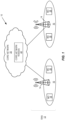
- FIG. 1 illustrates one example of a cellular communications network 10 in which embodiments of the present disclosure may be implemented.
- the cellular communications network 10 includes a Radio-Access Network (RAN) 12 that includes a number of radio access nodes.
- the radio access nodes are base stations 14 (e.g., LTE eNBs).
- the base stations 14 serve corresponding cells 16.
- Wireless devices 18 e.g., LTE UEs
- the base stations 14 may communicate with one another via a base-station-to-base-station interface (e.g., an LTE X2 interface).
- the base stations 14 are connected to a core network 20, which includes one or more core network nodes 22 (e.g., MMEs, Serving Gateways (S-GWs), P-GWs, etc.).
- MMEs Mobility Management Entity
- S-GWs Serving Gateways
- P-GWs Packed Access Management Entity
- Figure 2 illustrates the operation of one of the base stations 14 and one of the wireless devices 18 according to some embodiments of the present disclosure. Note that while processes are described herein as including “steps,” the “steps" may be performed in any suitable order unless explicitly stated or otherwise required. Further, optional steps are indicated by dashed lines. As illustrated in Figure 2 , the base station 14 optionally generates one or more transmit patterns for the wireless device 18 (step 100). Alternatively, the base station 14 may obtain the transmit pattern(s) for the wireless device 18 from an external source, e.g., another network node.
- an external source e.g., another network node.
- the transmit pattern(s) for the wireless device 18 is generated based on QoS requirements of the wireless device 18, one or more applications or services (e.g., Voice over LTE (VoLTE), file download, default access, etc.) of the wireless device 18, or the like, or any combination thereof.
- QoS requirements for a radio bearer group e.g., a LCG, which may include one or more radio bearers
- a QoS pattern e.g., b bits every p milliseconds
- the QoS pattern for the radio bearer group can then be used to generate a transmit pattern for the group (e.g., b bits every p milliseconds starting at time t ).
- the base station 14 transmits an indication of the transmit pattern(s) to the wireless device 18 (step 102).
- This indication may be transmitted, e.g., during bearer setup/creation and during bearer modification/deletion.
- the transmit pattern(s) is(are) for a respective radio bearer group.. Thus, for multiple radio bearer groups, a separate transmit pattern may be indicated for each group. In some embodiments, a separate transmit pattern may be indicated for each radio bearer group required to run one or more services and/or applications at a wireless device. In other embodiments, a number of transmit patterns are predefined (e.g., by standard), and the indication comprises an index or indices of the transmit pattern(s) for the wireless device 18.
- the indication includes information that defines the transmit pattern(s).
- the information that defines the transmit pattern(s) may include, for example, timing information that defines the timing of transmit opportunities (e.g., subframes or TTls that correspond to the transmit opportunities) in the transmit pattern and information that defines an amount of data that is expected to be transmitted in each of the transmit opportunities, where the same amount of data may be defined for all transmit opportunities in a particular pattern or different amounts of data may be defined for different transmit opportunities in a particular transmit pattern.
- each transmit pattern is associated with a respective LCG.
- a LCG is a group of logical channels identified by a unique LCG Identifier (ID).
- ID the mapping of logical channels to an LCG is set up during Radio Resource Control (RRC) configuration.
- RRC Radio Resource Control
- a logical channel is defined by the type of information that is transferred.
- Logical channels are generally classified into two groups, namely, control channels that are used for the transfer of control-plane information and data or traffic channels used for the transfer of user-plane information/data.
- LCGs are a mechanism by which, e.g., BSRs can be transmitted more efficiently (i.e., a BSR reports aggregate bits across all logical channels of an LCG).
- the transmit pattern for LCG 1 defines periodic transmit opportunities at a periodicity of p 1 milliseconds (i.e., a transmit opportunity occurs every p 1 milliseconds), where each transmit opportunity is an opportunity to transmit b 1 bits.
- the transmit pattern for LCG 1 defines a transmit opportunity for b 1 bits every p 1 milliseconds.
- the transmit pattern for LCG 1 also includes a starting time for the transmit pattern.
- the transmit pattern for LCG 2 defines periodic transmit opportunities at a periodicity of p 2 milliseconds (i.e., a transmit opportunity occurs every p 2 milliseconds), where each transmit opportunity is an opportunity to transmit b 2 bits.
- the transmit pattern for LCG 2 defines a transmit opportunity for b 2 bits every p 2 milliseconds.
- the transmit pattern for LCG 2 also includes a starting time for the transmit pattern.
- the transmit pattern for LCG 3 defines periodic transmit opportunities at a periodicity of p 3 milliseconds (i.e., a transmit opportunity occurs every p 3 milliseconds), where each transmit opportunity is an opportunity to transmit b 3 bits.
- the transmit pattern for LCG 3 defines a transmit opportunity for b 3 bits every p 3 milliseconds.
- the transmit pattern for LCG 3 also includes a starting time for the transmit pattern.
- the values of b 1 to b 3 and p 1 to p 3 may be selected or otherwise determined based on, for example, QoS requirements (e.g., bit rate and maximum delay requirements) for the LCGs.
- QoS requirements e.g., bit rate and maximum delay requirements
- the periodicity of a transmit pattern is also referred to herein as a delay constraint in that it defines the delay between transmit opportunities in the transmit pattern.
- the base station 14 pre-allocates resources in accordance with the transmit pattern(s) of the wireless device 18 (step 104). For example, the base station 14 may pre-allocate resources in accordance with the transmit pattern(s) as if the base station 14 expects to receive scheduling requests from the wireless device 18 for all of the transmit opportunities even though the wireless device 18 may not transmit SRs for all of the transmit opportunities, depending on conditions at the wireless device 18.
- the base station 14 pre-allocates resources for the wireless device 18 by building the uplink transmit patterns with specific inter-transmission delays and transmission sizes.
- the transmit patterns can be applied in two ways.
- the base station 14 maps a transmit pattern to actual frame offset or subframe numbers to start the pattern and the repeat it.
- the transmit pattern must be used only at specific frame offsets.
- the transmit pattern is independent of actual subframe numbers.
- the wireless device 18 must comply with the requirements such as delays between transmissions, but it is free to use any sub-frame(s).
- the wireless device 18 optionally (i.e., in some embodiments) generates a combined transmit pattern for the wireless device 18 based on the transmit patterns (step 106).
- Generation of the combined transmit pattern for the wireless device 18 for N LCGs, where N ⁇ 2, according to some embodiments of the present disclosure is illustrated in Figure 3 .
- the combined transmit pattern for the wireless device 18 includes a periodicity (i.e., inter-transmission period) that is equal to the shortest delay constraint (i.e., the shortest periodicity of the transmit patterns for LCG 1 to LCG N) and a bits per transmit opportunity that is calculated based on the bit rate requirements for LCG 1 to LCG N and the periodicity of the combined transmit pattern.
- a periodicity i.e., inter-transmission period
- the shortest delay constraint i.e., the shortest periodicity of the transmit patterns for LCG 1 to LCG N
- bits per transmit opportunity that is calculated based on the bit rate requirements for LCG 1 to LCG N and the periodicity of the combined transmit pattern.
- LCG 1 has a bit rate requirement of 64 kilobits per second (kbps) and a maximum delay requirement of 60 milliseconds (ms) (which can be referred to as QoS requirements that define a QoS pattern).
- LCG 2 has a bit rate requirement of 384 kbps and a maximum delay requirement of 33 ms.
- LCG 3 has a bit rate requirement of 15 kbps and a maximum delay requirement of 22 ms.
- the periodicity for the combined transmit pattern is the minimum periodicity (i.e., the minimum delay constraint) from among the individual transmit patterns for LCG 1 through LCG 3, which in this example is 22 ms. Then, using a 22 ms periodicity, the number of bits needed per transmission at the periodicity of 22 ms for each of the LCGs can be calculated as follows:
- the wireless device 18 determines when it is time to transmit a SR based on the individual transmit pattern(s) indicated in step 102 or, more specifically in some embodiments, the combined transmit pattern generated in step 106 (step 108).
- the decision of step 108 is, at least in some embodiments, triggered when there is some amount of data stored in an uplink buffer at the wireless device 18 (i.e., the decision process of step 108 may not need to be performed if there is no data in the buffer waiting for transmission).
- the transmit pattern defines times at which the wireless device 18 can transmit SRs. For example, if the transmit pattern defines transmit opportunities at a periodicity p , then the wireless device 18 decides whether or not to transmit SRs at the same or similar periodicity. In other words, the wireless device 18 decides whether or not to transmit a SR to be allocated resources for each transmit opportunity defined by the transmit pattern. So, prior to each transmit opportunity, the wireless device 18 decides whether to transmit a SR to be allocated resources for the transmit opportunity. If the wireless device 18 decides to transmit a SR, the wireless device 18 transmits a SR to the base station 14 to thereby request resources for the transmit opportunity (step 110).
- the base station 14 transmits a BSR grant to the wireless device 18 upon receiving the SR in step 110 (step 112).
- the wireless device 18 transmits a BSR to the base station 14 (step 114).
- the base station 14 allocates resources for the uplink transmission from the wireless device 18 (step 116) and transmits a data grant to the wireless device (step 118).
- the base station 14 since the base station 14 pre-allocates resources for the wireless device 18 in accordance with the transmit pattern(s), the base station 14 is enabled to promptly allocate and grant the resources for the wireless device 14 and there should not be a need for SR retransmissions. However, if there is a need for a SR retransmission, the wireless device 18 can wait until the next transmit opportunity instead of flooding the base station 14 with SR retransmissions for the same transmit opportunity.
- the wireless device 18 sends the SR in step 110 regardless of the amount of data waiting to be transmitted at the wireless device 18.
- the amount of data waiting to be transmitted may be substantially less (or more) than that expected for the transmit opportunity.
- the transmit pattern may indicate that the transmit opportunity is for 10,186 bits, but the amount of data in the buffer may be only 500 bits.
- the BSR procedure of steps 112 and 114 may be beneficial such that a proper amount of resources are allocated and granted in steps 116 and 118 (i.e., such that the amount of resources allocated and granted is that which is needed for the amount of data actually waiting to be transmitted at the wireless device 18).
- the wireless device 18 only transmits the SR in step 110 if the amount of data waiting to be transmitted at the wireless device 18 is greater than or equal to (or at least approximately equal to) the amount of data defined for the transmit opportunity in the transmit pattern.
- the BSR procedure may be avoided such that the base station 14 considers the SR in step 110 as a request for an amount of resources sufficient for the wireless device 18 to transmit the full amount of data defined for the transmit opportunity in the transmit pattern, in which case the base station 14 will automatically allocate and grant (in steps 116 and 118) an amount of resources sufficient for the wireless device 18 to transmit the amount of data defined for the transmit opportunity in the transmit pattern. Avoiding the BSR procedure is beneficial in that signaling is reduced.
- the wireless device 18 Upon receiving the data grant, optionally (in some embodiments), the wireless device 18 allocates the granted resources to the LCGs in accordance with their individual transmit patterns (step 120). In particular, if the wireless device 18 made the decision to transmit the SR in step 108 based on the combined transmit pattern for the wireless device 18, it may then be beneficial for the wireless device 18 to allocate the resulting granted resources to the different LCGs in accordance with their individual transmit patterns (or similarly based on their individual QoS requirements (e.g., bit rate and maximum delay requirements)). The wireless device 18 transmits data in accordance with the data grant (step 122).
- the wireless device 18 transmits data in accordance with the data grant (step 122).
- LCG i . delayBudget LCG i . pattern .delay ⁇ ( CurrentTTI ⁇ LCG i . LastTransmissionTTI . LCG[i].delayBudget is the delay budget for the i-th LCG, LCG[i].pattern.delay is the delay between transmit opportunities in the transmit pattern for the i-th LCG, CurrentTTI is the current TTI, and LCG[i].LastTransmissionTT! is the TTI in which a transmission for the i-th LCG was last transmitted.
- the wireless device 18 selects the LCG(s) to which to allocate the granted resources in increasing order of their delay budget, starting with the smallest value. If two LCGs have the same delay budget, the wireless device 18 may use priorities associated with the LCGs (e.g., from priority field from Prioritized Bit Rate (PBR) parameters) to break the tie.
- PBR parameters include: (1) priority, which is used to decide which LCG to which to allocate a grant, (2) bit rate, which is used to check which LCG is falling below the expected bit rate, and (3) bucket size duration, which is how much to buffer for a LCG.
- the PBR parameters are signaled to the wireless device 18 when the LCG is being set up.
- the wireless device 18 allocates each of the LCGs in the tie up to the amount of resources defined for the transmit opportunity in the transmit pattern. If there are any remaining resources from the grant, the wireless device 18 allocates these resources to the next LCGs. The wireless device 18 then transmits data for the LCGs according to their allocations.
- the generation of the transmit pattern(s) (step 100) and the transmission of the indication of the transmit pattern(s) are described with respect to the process of Figure 2 , the present disclosure is not limited thereto.
- the generation of the transmit pattern(s) and/or the transmission of the indication of the transmit pattern(s) may be performed independently from the rest of the process of Figure 2 (i.e., in some embodiments, steps 104-122 are optional).
- the transmit pattern(s) are generated by the base station 14 and signaled from the base station 14 to the wireless device 18 in the example of Figure 2 , the present disclosure is not limited thereto.
- the transmit pattern(s) may be generated by some other network node and, e.g., signaled to the base station 14 for subsequent signaling to the wireless device 18 or signaled from the network node to the wireless device 18 (e.g., via a connection that passes through the base station 14).
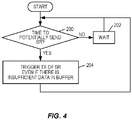
- Figures 4 through 8 are flow charts that illustrate example embodiments of the decision in step 108 of Figure 2 .
- the decision in step 108 is based on a combined transmit pattern for the wireless device 18, then these processes are performed based on the combined transmit pattern (and potentially any individual transmit patterns that are not included in the combined transmit pattern due to, e.g., configuration).
- the decision in step 108 is based on an individual transmit pattern for, e.g., a respective LCG. In these cases, the decision in step 108, and thus the processes of Figures 4 through 8 , may be performed separately for each individual transmit pattern.
- the wireless device 18 determines whether it is time to potentially transmit a SR (step 200). As noted above, in some embodiments, the process is performed based on a combined transmit pattern. In other embodiments, the process is performed based on an individual transmit pattern. The transmit pattern (either a combined transmit pattern or an individual transmit pattern) defines multiple transmit opportunities and the times at which these multiple transmit opportunities occur. In step 200, the wireless device 18 determines whether it is time to transmit a SR to request resources for a next, or upcoming, transmit opportunity in the transmit pattern, if so desired by the wireless device 18.
- the wireless device 18 may use a timer t SR that expires every p milliseconds for the decision in step 200, where the timer t SR expires X milliseconds prior to each transmit opportunity in the combined transmit pattern. If it is not time to transmit a SR for the next transmit opportunity, the wireless device 18 waits (step 202).
- the wireless device 18 triggers the transmission of a SR (i.e., triggers step 110 of Figure 2 ) even if there is insufficient data in the uplink buffer at the wireless device 18 waiting to be transmitted (step 204).
- insufficient data refers to an amount of data that is less than that defined for the transmit opportunity in the transmit pattern.
- the BSR procedure of steps 112 and 114 of Figure 2 may be beneficial so that the base station 14 may determine an amount of resources to allocate for the wireless device 18 that is appropriate for the amount of data in the buffer waiting to the transmitted at the wireless device 18.
- Figure 5 illustrates an embodiment of the decision in step 108 of Figure 2 according to some other embodiments of the present disclosure in which transmission of a SR is not triggered unless there is enough data in the buffer at the wireless device 18 waiting to be transmitted.
- the wireless device 18 determines whether it is time to potentially transmit a SR (step 300).
- the process is performed based on a combined transmit pattern.
- the process is performed based on an individual transmit pattern.
- the transmit pattern (either a combined transmit pattern or an individual transmit pattern) defines multiple transmit opportunities and the times at which these multiple transmit opportunities occur.
- the wireless device 18 determines whether it is time to transmit a SR to request resources for a next, or upcoming, transmit opportunity in the transmit pattern, if so desired by the wireless device 18. For example, if the transmit pattern defines transmit opportunities for the transmission of b bits every p milliseconds and if a SR for a transmit opportunity must be transmitted X milliseconds prior to that transmit opportunity, then the wireless device 18 may use a timer t SR that expires every p milliseconds for the decision in step 300, where the timer t SR expires X milliseconds prior to each transmit opportunity in the combined transmit pattern. If it is not time to transmit a SR for the next transmit opportunity, the wireless device 18 waits (step 302).
- the wireless device 18 determines whether there is enough, or a sufficient amount, of data in the buffer at the wireless device 18 waiting to be transmitted (step 304).
- “enough data” or “a sufficient amount of data” refers to an amount of data that is greater than or equal to (or at least approximately or nearly equal to) the amount of data defined for the next transmit opportunity in the transmit pattern. If there is not enough data in the buffer, then the wireless device 18 waits for the next transmit opportunity.
- the wireless device 18 triggers the transmission of a SR (i.e., triggers step 110 of Figure 2 ) (step 306).
- a SR i.e., triggers step 110 of Figure 2
- the BSR procedure of steps 112 and 114 of Figure 2 may be avoided.
- the SR can be viewed by the base station 14 as a request for an amount of resources that is sufficient for the wireless device 18 to transmit the amount of data defined for the transmit occurrence in the transmit pattern. As such, a BSR is not needed.
- the BSR procedure may be performed.
- Figure 6 illustrates an embodiment of the decision in step 108 of Figure 2 according to some other embodiments of the present disclosure.
- the process is performed based on a combined transmit pattern.
- the process is performed based on an individual transmit pattern.
- the transmit pattern (either a combined transmit pattern or an individual transmit pattern) defines multiple transmit opportunities and the times at which these multiple transmit opportunities occur.
- the wireless device 18 determines whether there is enough, or a sufficient amount, of data in the buffer at the wireless device 18 waiting to be transmitted (step 400).
- “enough data” or "a sufficient amount of data” refers to an amount of data that is greater than or equal to (or at least approximately or nearly equal to) the amount of data defined for the next transmit opportunity in the transmit pattern. If there is not enough data in the buffer, then the wireless device 18 waits until there is enough data in the buffer (step 402).
- the wireless device 18 determines whether to trigger transmission of a SR (i.e., determines whether to trigger step 110 of Figure 2 ) based on some predefined algorithm (step 404).
- the predefined algorithm may be an algorithm in which the SR resource is a periodic resource allocated by the base station 14 for the wireless device 18.
- the SR resource may have a periodicity of, e.g., 5 ms and the wireless device 18 may have the choice of sending a SR every 5 ms. If not, the wireless device 18 continues to wait.
- the wireless device 18 determines that a SR should be triggered, the wireless device 18 triggers the transmission of a SR (i.e., triggers step 110 of Figure 2 ) (step 406).
- a SR i.e., triggers step 110 of Figure 2
- the BSR procedure of steps 112 and 114 of Figure 2 may be avoided.
- the SR can be viewed by the base station 14 as a request for an amount of resources that is sufficient for the wireless device 18 to transmit the amount of data defined for the transmit occurrence in the transmit pattern. As such, a BSR is not needed.
- the BSR procedure may be performed.
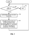
- Figure 7 illustrates an embodiment of the decision in step 108 of Figure 2 according to some other embodiments of the present disclosure in which the SR includes an implicit or explicit indication of an amount of data/resources being requested.
- the wireless device 18 determines whether it is time to potentially transmit a SR (step 500). As noted above, in some embodiments, the process is performed based on a combined transmit pattern. In other embodiments, the process is performed based on an individual transmit pattern. The transmit pattern (either a combined transmit pattern or an individual transmit pattern) defines multiple transmit opportunities and the times at which these multiple transmit opportunities occur. In step 500, the wireless device 18 determines whether it is time to transmit a SR to request resources for a next, or upcoming, transmit opportunity in the transmit pattern, if so desired by the wireless device 18. If it is not time to transmit a SR for the next transmit opportunity, the wireless device 18 waits (step 502).
- the wireless device 18 also determines an amount of data in the buffer at the wireless device 18 waiting for transmission (step 504).
- the wireless device 18 then triggers a SR with an explicit or implicit indication of a desired amount of data to be transmitted (i.e., the amount of data in the buffer) (step 506).
- This indication may be an indication of the desired amount of data relative to the amount of data defined for the next transmit occurrence in the transmit pattern.
- different types of SRs may be used to indicate different amounts of data.
- a first type of SR may be used to indicate that the full amount of data is waiting for transmission (i.e., the amount of data in the buffer is greater than or equal to or at least approximately or nearly equal to the amount of data defined for the transmit opportunity in the transmit pattern)
- a second type of SR may be used to indicate that less than the full amount (e.g., 1 ⁇ 2 the full amount) is waiting for transmission, etc.
- the different types of SRs may be distinguished by the resources (e.g., time resources - e.g., TTIs) used for transmission of the SRs.
- SR opportunities For example, for each transmit opportunity, there two (or more) SR opportunities (resources) allocated for the wireless device 18.
- the SR is transmitted on one of the SR opportunities to indicate a first amount (e.g., full amount) of data is waiting for transmission, and the SR is transmitted on another one of the SR opportunities to indicate a second amount (e.g., 1 ⁇ 2 amount) of data is waiting for transmission.
- the types of SRs can be distinguished, for example, by allocating two SR opportunities for the wireless device 18 some milliseconds apart, one to mean sufficient data, the other to mean "some data available."
- the base station 14 will match the time at which the SR is received with the meaning/amount of data waiting for transmission.
- SRs can be defined in this way for more granularity of the buffer size with respect to the pre-allocated transmission size.
- a third SR (at a different time slot) could mean the buffer is at least twice as large as the pre-allocated transmission bits.
- the SR may include an explicit indication of the amount of data waiting for transmission at the wireless device 18.
- the SR may, for example, use a new format.
- a new Physical Uplink Control Channel (PUCCH) format may be used to transmit the SR where the new PUCCH format defines, for example, the SR as a three bit long field (instead of a one bit long field as currently defined).
- a three bit long SR allows the wireless device 18 to indicate eight levels/amounts of data waiting in the buffer at the wireless device 18 for transmission with respect to the pre-signaled "grant size in bits," which is the amount of data defined for the transmit occurrence in the transmit pattern.
- the wireless device 18 can signal the SR including the amount of data waiting in the buffer for transmission to the base station 14 as follows:
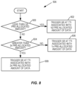
- Figure 8 is a flow chart that illustrates step 506 of Figure 7 in more detail according to one example.
- the wireless device 18 determines whether the amount of data in the buffer waiting for transmission is less than 1 ⁇ 2 of the pre-allocated amount of data (i.e., less than 1 ⁇ 2 of the amount of data defined for the transmit opportunity in the transmit pattern) (step 600). If so, the wireless device 18 triggers transmission of the SR at, or in, a TTI that is associated with 1 ⁇ 2 of the pre-allocated amount of data (step 602).
- the wireless device 18 triggers transmission of the SR at, or in, a TTI that is associated with one times the pre-allocated amount of data (i.e., the full amount) (step 606). If the amount of data in the buffer waiting for transmission is greater than two times the pre-allocated amount of data, the wireless device 18 triggers transmission of the SR at, or in, a TTI that is associated with two times the pre-allocated amount of data (step 608).
- threshold and the number of thresholds used in the example of Figure 8 are only an example.
- the number of thresholds and the particular thresholds used may vary depending on the particular implementation. For example, a greater number of thresholds may be used when more granularity is desired for the indication of the amount of data waiting for transmission.
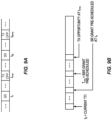
- Figure 9A illustrates one example of a transmit pattern and corresponding pre-scheduled times for transmitting SRs according to some embodiments of the present disclosure.
- the pre-scheduled times for transmitting SRs are "pre-scheduled" in that resources for transmitting the SRs are reserved.
- the BSR resources are allocated only as a result of a SR.
- the transmit pattern includes transmit opportunities at times (e.g., TTIs or subframes) t n+m , t 2n+m t 3n+m , etc.
- the periodicity of the transmit pattern in this example is n.
- SRs are pre-scheduled at times t n , t 2n , t 3n , etc.
- the wireless device 18 decides (e.g., according to any of the decision processes described herein) to transmit a SR for resources in the transmit opportunity at t n+m , then the wireless device 18 transmits a SR at t n .
- the value of m may be, e.g., predefined by standard. For example, the value of m may be 4 such that a SR is transmitted four TTIs, or subframes, before the respective transmit opportunity.
- Figure 9B illustrates timing of a SR with respect to a transmit opportunity in a transmit pattern in more detail according to one example embodiment.
- a SR is pre-scheduled at t n , where m is, e.g., predefined.
- a BSR grant is pre-scheduled at t n+x , where x ⁇ m.
- the wireless device 18 decides, e.g., at the current TTI t 0 , whether to transmit a SR to request resources in the transmit opportunity at t n+m .
- the wireless device 18 If the wireless device 18 decides to transmit a SR, the wireless device 18 transmits the SR at t n .
- the wireless device 18 receives a BSR grant and, in response, transmits a BSR at t n+x .
- the wireless device 18 then receives a data grant and, in response, transmits uplink data at t n+m .
- step 100 of Figure 2 an indication of the one or more transmit patterns for the wireless device 18 is signaled from the base station 14 to the wireless device 18.
- this example implementation extends the RRCConnectionReconfiguration message described in 3GPP Technical Specification (TS) 36.331 (V13.0.0) to include transmit pattern information.
- This message already carries information for bearer creation and modification, Discontinuous Reception (DRX) configuration and reconfiguration, etc.
- the LogicalChannelConfig Information Element of the RRCConnectionReconfiguration message can be extended to include a number of transmit pattern IDs (transmissionPatternIds).
- a transmit pattern ID is an identifier of a transmit pattern used by the logical channel.
- Each transmit pattern is defined by a number of parameters (e.g., patternType, patternTrigger, minlnterTxDelay, etc.).
- the transmit patterns have several applications. Much of the discussion herein focuses on the use of transmit patterns for SRs for the uplink. However, the transmit patterns may have other applications. For example, for downlink, the scheduler can follow the transmit pattern and whenever the system is not congested can allow up to the maximum payloads. Whenever the system is loaded the scheduler may reduce the transmissions to minimum payloads.
- VoLTE traffic has periods of data packets and periods of silence packets. Each period is represented by at least one pattern.
- the switching is triggered by things like packet size and inter-packet delays.
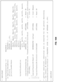
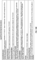
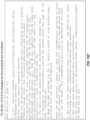
- Figures 10F and 10G illustrate one example of how 3GPP TS 36.321 (V13.0.0) can be modified to incorporate one embodiment of the present disclosure.
- the wireless device 18 waits for two conditions to occur before sending a SR for a respective transmit opportunity in a transmit pattern. These two conditions are: (1) the amount of data in the buffer, or queue, waiting for transmission is greater than or equal to minPayloads (i.e., the amount of data pre-allocated or pre-scheduled for the transmit occasion) and (2) it is time to send a SR for the transmit occasion, which in this example is determined by the expiry of a minlnterTxDelay period/timer.
- minPayloads i.e., the amount of data pre-allocated or pre-scheduled for the transmit occasion
- the base station 14 When the base station 14 receives the SR, the base station 14 sends a data grant for an amount of resources that is sufficient for the wireless device 18 to transmit data of size minPayloads without performing the BSR procedure.
- the wireless device 18 uses the individual transmit patterns for the LCGs to allocate the granted resources to the LCGs.
- the allocation, or transmission priority, is decided as illustrated in Figures 10F and 10G .
- the resources allocated for SRs are periodic resources allocated to the wireless device 18 by the base station 14.
- the SR resources can be modified to (better) align with the transmit patterns of the wireless device 18.
- the base station 14 may further operate to configure or otherwise modify the SR resources (i.e., the SR transmit opportunities) for the wireless device 18 based on the transmit pattern(s) for the wireless device 18.
- Example 1 The combined transmit pattern for the wireless device 18 specifies transmit opportunities with a minimum waiting period of 40 ms between transmit opportunities.
- the SR resources can be also allocated with a 40 ms periodicity.
- Example 2 The combined transmit pattern of the wireless device 18 specifies a minimum wait of 50 ms between transmit opportunities.
- the SR resource is set to a periodicity of 10 ms with the following meaning attached to each SR transmitted within a 50 ms window:
- transmit patterns are generated based on QoS patterns for the respective radio bearers / logical channels.
- a QoS pattern is generic information that repeats in time but without mapping to resources, subframe offsets, etc.
- a transmit pattern includes a pattern of transmit opportunities that are mapped to specific resources.
- a respective transmit pattern may include a transmit opportunity for 244 bits every 20 ms, where each transmit opportunity is mapped to respective resources (e.g., respective TTIs or subframes).
- a transmit pattern is mapped to resources by specifying a starting time for a first transmit opportunity in the transmit pattern.
- QoS patterns can be signaled between nodes.
- the wireless device 18 may determine QoS patterns for its logical channels / radio bearers and signal those QoS patterns to the base station 14, which may then use the QoS patterns to determine transmit patterns for the wireless device 18 and signal those transmit patterns to the wireless device 18, as described above.
- a QoS pattern may include one or more sub-patterns. Where there is more than one sub-pattern, a trigger may be specified to determine when to switch between the different sub-patterns.
- dynamic switching between the different sub-patterns of a QoS pattern is provided.
- the network e.g., the base station 14
- Figure 11 illustrates an example of a QoS pattern for best effort traffic in which the QoS pattern includes two sub-patterns.
- the first sub-pattern is illustrated on the left-hand side of Figure 11 and is as follows:
- Figure 12 illustrates an example of a QoS pattern for VoLTE traffic in which the example QoS patterns include two sub-patterns.
- the first sub-pattern is illustrated on the left-hand side of Figure 12 and is as follows:
- QoS patterns may have additional or alternative uses to those disclosed herein with respect to transmit patterns. Some examples are:
- a traffic flow (i.e., a connection, bearer, service, etc.) can be split into sub-flows for the purpose of transmitting portions of it via different links or paths by creating sub-patterns for each sub-flow. The sub-patterns are then signaled to the receiving entities.
- Sub-patterns can be applied to case such as carrier aggregation where multiple cells are used to transmit traffic for a bearer.
- a traffic flow i.e., a connection, bearer, service, etc.
- the sub-flows need to be combined at the receiver.
- Sub-patterns signaled by the sender ahead of time can be used to recombine the sub-flows into flows.
- Sub-patterns tell the receiver which paths (i.e., links, connection, bearers, or cells) are sending what and at what time.
- Sub-pattern combination can be used by UE (or base station) in cases such as carrier aggregation where multiple cells are used to transmit traffic for a bearer.
- Traffic shaping and policing is achieved using QoS patterns by having a transmitting entity follow the requirements and constraints specified in one or more patterns for a specific link, interface, bearer, etc.
- Embodiments of the present disclosure increase the capacity of the cell 16 and the capacity of the base station 14 as a whole for one or more of following reasons:
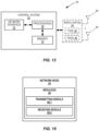
- FIG. 13 is a schematic block diagram of a network node 24 according to some embodiments of the present disclosure.
- the network node 24 may be, for example, a radio access node such as, for example, a base station 14 or a core network 22.
- the network node 24 includes a control system 26 that includes one or more processors 28 (e.g., Central Processing Units (CPUs), Application Specific Integrated Circuits (ASICs), Field Programmable Gate Arrays (FPGAs), and/or the like), memory 30, and a network interface 32.
- processors 28 e.g., Central Processing Units (CPUs), Application Specific Integrated Circuits (ASICs), Field Programmable Gate Arrays (FPGAs), and/or the like
- memory 30 e.g., RAM, RAM, RAM, and/or the like
- the network node 24 is a radio access node
- the network node 24 also includes one or more radio units 34 that each includes one or more transmitters 36 and one or more receivers 38 coupled to one
- the radio unit(s) 34 is external to the control system 26 and connected to the control system 26 via, e.g., a wired connection (e.g., an optical cable). However, in some other embodiments, the radio unit(s) 34 and potentially the antenna(s) 40 are integrated together with the control system 26.
- the one or more processors 28 operate to provide one or more functions of a network node as described herein. In some embodiments, the function(s) are implemented in software that is stored, e.g., in the memory 30 and executed by the one or more processors 28.
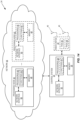
- FIG 14 is a schematic block diagram that illustrates a virtualized embodiment of the network node 24 according to some embodiments of the present disclosure.
- a "virtualized” network node e.g., a virtualized base station or a virtualized radio access node
- a virtualized network node is an implementation of the network node 24 in which at least a portion of the functionality of the network is implemented as a virtual component (e.g., via a virtual machine(s) executing on a physical processing node(s) in a network(s)).
- the network node 24 includes the control system 26 that includes the one or more processors 28 (e.g., CPUs, ASICs, FPGAs, and/or the like), the memory 30, and the network interface 32 and, depending on the type of network node, the one or more radio units 34 that each includes the one or more transmitters 36 and the one or more receivers 38 coupled to the one or more antennas 40, as described above.
- the control system 26 is connected to the radio unit(s) 34 via, for example, an optical cable or the like.
- the control system 26 is connected to one or more processing nodes 42 coupled to or included as part of a network(s) 44 via the network interface 32.
- Each processing node 42 includes one or more processors 46 (e.g., CPUs, ASICs, FPGAs, and/or the like), memory 48, and a network interface 50.
- functions 52 of the network node 24 are implemented at the one or more processing nodes 42 or distributed across the control system 26 and the one or more processing nodes 42 in any desired manner.
- some or all of the functions 52 of the network node 24 described herein are implemented as virtual components executed by one or more virtual machines implemented in a virtual environment(s) hosted by the processing node(s) 42.
- additional signaling or communication between the processing node(s) 42 and the control system 26 is used in order to carry out at least some of the desired functions 52.
- control system 26 may not be included, in which case the radio unit(s) 34, if present, communicate directly with the processing node(s) 42 via an appropriate network interface(s).
- the network node 24 is not a radio access node (e.g., a core network node 22)
- the network node 24 may be entirely virtualized (i.e., there may be no control system 26 or radio unit(s) 34.
- a computer program including instructions which, when executed by at least one processor, causes the at least one processor to carry out the functionality of a network node or a node (e.g., a processing node 42) implementing one or more of the functions 52 of the network node in a virtual environment according to any of the embodiments described herein is provided.
- a carrier comprising the aforementioned computer program product is provided.
- the carrier is one of an electronic signal, an optical signal, a radio signal, or a computer readable storage medium (e.g., a non-transitory computer readable medium such as memory).
- FIG. 15 is a schematic block diagram of the network node 24 according to some other embodiments of the present disclosure.
- the network node 24 includes one or more modules 54, each of which is implemented in software.
- the module(s) 54 provide the functionality of the network node 24 described herein.
- the module(s) 54 may include one or modules that perform the operations of the network node 24 described with respect to Figure 2 above.
- the module(s) 54 may include a transmitting module 54-1 operable to transmit, to the wireless device 18, an indication of one or more transmit patterns for one or more logical channel groups, wherein each transmit pattern of the one or more transmit patterns defines a plurality of transmit opportunities, as described above.
- the module(s) 54 may also include a receiving module 54-2 operable to receive a SR from the wireless device 18 that requests resources for a transmission of uplink data from the wireless device 18 in accordance with the one or more transmit patterns, as described above.
- the module(s) 54 may include additional modules that are operable to perform the other functions of the network node 24 described herein.
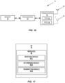
- FIG 16 is a schematic block diagram of the wireless device 18 according to some embodiments of the present disclosure.
- the wireless device 18 includes one or more processors 56 (e.g., CPUs, ASICs, FPGAs, and/or the like), memory 58, and one or more transceivers 60 each including one or more transmitters 62 and one or more receivers 64 coupled to one or more antennas 66.
- processors 56 e.g., CPUs, ASICs, FPGAs, and/or the like
- memory 58 e.g., RAM, programmable gate array, and/or the like
- transceivers 60 each including one or more transmitters 62 and one or more receivers 64 coupled to one or more antennas 66.
- the functionality of the wireless device 18 described above may be fully or partially implemented in software that is, e.g., stored in the memory 58 and executed by the processor(s) 56.
- a computer program including instructions which, when executed by at least one processor, causes the at least one processor to carry out the functionality of the wireless device 18 according to any of the embodiments described herein is provided.
- a carrier comprising the aforementioned computer program product is provided.
- the carrier is one of an electronic signal, an optical signal, a radio signal, or a computer readable storage medium (e.g., a non-transitory computer readable medium such as memory).
- FIG 17 is a schematic block diagram of the wireless device 18 according to some other embodiments of the present disclosure.
- the wireless device 18 includes one or more modules 68, each of which is implemented in software.
- the one or more modules 68 include one or more modules that operate to perform the process described above with respect to Figure 2 .
- the module(s) 68 may include a receiving module 68-1 operable to receive an indication of one or more transmit patterns for one or more logical channel groups, wherein each transmit pattern of the one or more transmit patterns defines a plurality of transmit opportunities, as described above.
- the module(s) 68 may also include a determining module 68-2 operable to, based on the one or more transmit patterns, determine when to transmit a SR for transmission of data in accordance with the one or more transmit patterns.
- the module(s) 68 may also include a transmitting module 68-3 operable to, upon determining that it is time to transmit a SR, transmit a SR to a radio access node to thereby request resources for transmission of uplink data in accordance with the one or more transmit patterns.
- the module(s) 68 may include additional modules that are operable to perform the other functions of the wireless device 18 described herein.
Landscapes
- Engineering & Computer Science (AREA)
- Signal Processing (AREA)
- Computer Networks & Wireless Communication (AREA)
- Quality & Reliability (AREA)
- Mobile Radio Communication Systems (AREA)
Claims (6)
- Procédé de fonctionnement d'un dispositif sans fil (18) dans un réseau de communications cellulaire (10), comprenant :la réception (102) d'une indication d'un ou plusieurs modèles de transmission pour un ou plusieurs groupes de canaux logiques, dans lequel chaque modèle de transmission parmi le ou les modèles de transmission définit une pluralité d'opportunités de transmission ;dans lequel le ou les modèles de transmission comprennent une pluralité de modèles de transmission, chaque modèle de transmission comprenant une contrainte de délai qui définit un laps de temps entre des opportunités de transmission adjacentes dans la pluralité d'opportunités de transmission définies par le modèle de transmission ;la génération (106) d'un modèle de transmission combiné pour le dispositif sans fil (18) sur la base du ou des modèles de transmission, dans lequel une périodicité du modèle de transmission combiné est une contrainte de délai minimale parmi la pluralité de modèles de transmission ;sur la base du ou des modèles de transmission, la détermination (108) du moment pour transmettre une demande de planification pour transmission de données conformément au ou aux modèles de transmission ;dans lequel la détermination (108) du moment pour transmettre une demande de planification comprend la détermination (108) du moment pour transmettre une demande de planification sur la base du modèle de transmission combiné ; etlorsqu'on détermine (108) qu'il est temps de transmettre une demande de planification, la transmission (110) d'une demande de planification à un noeud d'accès radio (14) pour demander de ce fait des ressources pour transmission de données de liaison montante conformément au ou aux modèles de transmission.
- Procédé selon la revendication 1 dans lequel la détermination (108) du moment pour transmettre une demande de planification comprend :le fait de déterminer (300) s'il est temps de transmettre une demande de planification pour une opportunité de transmission suivante du ou des modèles de transmission ;le fait de déterminer (304) si une quantité de données en attente de transmission en liaison montante est supérieure ou égale à une quantité prédéfinie de données ; etlorsqu'on détermine qu'il est temps de transmettre une demande de planification et que la quantité de données en attente de transmission en liaison montante est supérieure ou égale à la quantité prédéfinie de données, l'initiation (306) de la transmission (110) de la demande de planification, et, facultativement,le procédé comprenant en outre :en réponse à la transmission (110) de la demande de planification, la réception (118) d'un octroi d'une quantité de ressources pour transmission en liaison montante de la quantité prédéfinie de données sans transmettre d'abord un rapport d'état de tampon au noeud d'accès radio (14) ; etla transmission (122) de la quantité prédéfinie de données conformément à l'octroi.
- Procédé selon la revendication 2 dans lequel l'opportunité de transmission suivante est une opportunité de transmission suivante définie par un parmi le ou les modèles de transmission, et la quantité prédéfinie de données est une quantité de données définie pour l'opportunité de transmission suivante, ou
dans lequel le ou les modèles de transmission sont une pluralité de modèles de transmission, l'opportunité de transmission suivante est une opportunité de transmission suivante définie par un modèle de transmission combiné généré sur la base de la pluralité de modèles de transmission, et la quantité prédéfinie de données est une quantité de données définie pour l'opportunité de transmission suivante dans le modèle de transmission combiné. - Procédé selon la revendication 1 dans lequel la détermination (108) du moment pour transmettre une demande de planification comprend :le fait de déterminer (400) si une quantité de données en attente de transmission en liaison montante est supérieure ou égale à une quantité prédéfinie de données ;le fait de déterminer (404) s'il est temps de transmettre une demande de planification à l'aide d'un algorithme prédéfini ; etlorsqu'on détermine que la quantité de données en attente de transmission en liaison montante est supérieure ou égale à la quantité prédéfinie de données et qu'il est temps de transmettre une demande de planification, l'initiation (406) de la transmission (110) de la demande de planification.
- Procédé selon l'une quelconque des revendications 1 à 4 dans lequel chaque opportunité de transmission de la pluralité d'opportunités de transmission est une probabilité de transmission en liaison montante d'une quantité définie de données depuis le dispositif sans fil (18) à un moment défini, et, facultativement,
dans lequel, pour chaque modèle de transmission parmi le ou les modèles de transmission, la quantité définie de données est la même pour chacune parmi la pluralité d'opportunités de transmission définies pour le modèle de transmission. - Dispositif sans fil (18) pour fonctionnement dans un réseau de communications cellulaire (10), comprenant :
un circuit contenant des instructions qui, lorsqu'elles sont exécutées, amènent le dispositif sans fil (18) à :recevoir une indication d'un ou plusieurs modèles de transmission pour un ou plusieurs groupes de canaux logiques, dans lequel chaque modèle de transmission parmi le ou les modèles de transmission définit une pluralité d'opportunités de transmission ;dans lequel le ou les modèles de transmission comprennent une pluralité de modèles de transmission, chaque modèle de transmission comprenant une contrainte de délai qui définit un laps de temps entre des opportunités de transmission adjacentes dans la pluralité d'opportunités de transmission définies par le modèle de transmission ;générer un modèle de transmission combiné pour le dispositif sans fil (18) sur la base du ou des modèles de transmission, dans lequel une périodicité du modèle de transmission combiné est une contrainte de délai minimale parmi la pluralité de modèles de transmission ;sur la base du ou des modèles de transmission, déterminer le moment pour transmettre une demande de planification pour transmission de données conformément au ou aux modèles de transmission ;dans lequel la détermination du moment pour transmettre une demande de planification comprend la détermination du moment pour transmettre une demande de planification sur la base du modèle de transmission combiné ; etlorsqu'on détermine qu'il est temps de transmettre une demande de planification, transmettre une demande de planification à un noeud d'accès radio (14) pour demander de ce fait des ressources pour transmission de données de liaison montante conformément au ou aux modèles de transmission.
Applications Claiming Priority (1)
| Application Number | Priority Date | Filing Date | Title |
|---|---|---|---|
| PCT/IB2016/053371 WO2017212314A1 (fr) | 2016-06-08 | 2016-06-08 | Systèmes et procédés de signalisation et d'utilisation de motifs de transmission |
Publications (2)
| Publication Number | Publication Date |
|---|---|
| EP3469843A1 EP3469843A1 (fr) | 2019-04-17 |
| EP3469843B1 true EP3469843B1 (fr) | 2023-03-08 |
Family
ID=56119714
Family Applications (1)
| Application Number | Title | Priority Date | Filing Date |
|---|---|---|---|
| EP16728738.2A Active EP3469843B1 (fr) | 2016-06-08 | 2016-06-08 | Systèmes et procédés de signalisation et d'utilisation de motifs de transmission |
Country Status (3)
| Country | Link |
|---|---|
| US (1) | US10785789B2 (fr) |
| EP (1) | EP3469843B1 (fr) |
| WO (1) | WO2017212314A1 (fr) |
Families Citing this family (10)
| Publication number | Priority date | Publication date | Assignee | Title |
|---|---|---|---|---|
| CN109937596B (zh) * | 2016-11-11 | 2021-02-26 | Oppo广东移动通信有限公司 | 调度终端设备的方法、网络设备和终端设备 |
| GB2562367B (en) * | 2017-03-23 | 2021-03-10 | Samsung Electronics Co Ltd | Improvements in and relating to scheduling requests (SR) in a telecommunication system |
| US11291036B2 (en) * | 2017-03-24 | 2022-03-29 | Qualcomm Incorporated | Scheduling requests and buffer status reports for low latency wireless communications |
| GB2563245B (en) * | 2017-06-07 | 2021-06-02 | Samsung Electronics Co Ltd | Improvements in and relating to scheduling requests in a telecommunication system |
| WO2019069132A1 (fr) | 2017-10-02 | 2019-04-11 | Lenovo (Singapore) Pte, Ltd. | Contrôle de puissance de liaison montante |
| US11051324B2 (en) | 2018-01-23 | 2021-06-29 | Qualcomm Incorporated | Multi-bit scheduling request |
| JP2021072454A (ja) * | 2018-02-27 | 2021-05-06 | ソニー株式会社 | 端末装置、通信制御装置、基地局、ゲートウェイ装置、制御装置、方法及び記録媒体 |
| US10812125B1 (en) * | 2019-05-31 | 2020-10-20 | Intel Corporation | Radiation exposure control for beamforming technologies |
| US12389390B2 (en) * | 2020-05-15 | 2025-08-12 | Qualcomm Incorporated | User equipment processing capability indication |
| US12588027B2 (en) * | 2021-02-26 | 2026-03-24 | Lg Electronics Inc. | Method and apparatus for transmitting data unit based on control uplink grant in wireless communication system |
Family Cites Families (16)
| Publication number | Priority date | Publication date | Assignee | Title |
|---|---|---|---|---|
| EP2237633A1 (fr) | 2009-04-03 | 2010-10-06 | Panasonic Corporation | Rapport de statut de tampon dans un système de communication mobile |
| TWI389506B (zh) * | 2009-12-25 | 2013-03-11 | 亞信電子股份有限公司 | Test System and Method of Ethernet Solid Layer Layer |
| EP2524561B1 (fr) * | 2010-01-13 | 2014-11-12 | Telefonaktiebolaget L M Ericsson (PUBL) | Procédé et agencements dans un système de communication sans fil |
| US8995259B2 (en) | 2011-07-26 | 2015-03-31 | Telefonaktiebolaget L M Ericsson (Publ) | Systems and methods for resource booking for admission control and scheduling using DRX |
| US8767539B2 (en) | 2011-07-26 | 2014-07-01 | Telefonaktiebolaget L M Ericsson (Publ) | Systems and methods for resource booking for admission control and scheduling |
| WO2013025139A1 (fr) * | 2011-08-15 | 2013-02-21 | Telefonaktiebolaget L M Ericsson (Publ) | Procédé et agencement pour gérer une demande d'ordonnancement |
| US9532373B2 (en) * | 2011-08-22 | 2016-12-27 | Telefonaktiebolaget Lm Ericsson (Publ) | Collision resolution for PUCCH scheduling requests |
| WO2014180351A1 (fr) * | 2013-05-10 | 2014-11-13 | Mediatek Singapore Pte. Ltd. | Mécanisme amélioré de demande de programmation à une pluralité de programmateurs dans un réseau sans fil avec agrégation de porteuses entre stations de base |
| CN111031573B (zh) * | 2013-05-17 | 2023-04-18 | 寰发股份有限公司 | 上报bsr的方法以及用户设备 |
| CN109510697B (zh) * | 2013-07-04 | 2021-07-06 | 韩国电子通信研究院 | 处理无线电链路故障的方法 |
| KR20150020018A (ko) * | 2013-08-14 | 2015-02-25 | 삼성전자주식회사 | 이동 통신 시스템에서 복수의 캐리어를 이용하는 데이터 송수신 방법 및 장치 |
| EP2928252B1 (fr) * | 2014-04-02 | 2018-01-31 | Telefonaktiebolaget LM Ericsson (publ) | Commander les requêtes d'ordonnancement |
| US10057918B2 (en) | 2014-08-08 | 2018-08-21 | Telefonaktiebolaget Lm Ericsson (Publ) | Coordination between prose BSR and cellular BSR |
| EP3286972B1 (fr) * | 2015-04-22 | 2019-05-15 | Intel IP Corporation | Demande de planification reposant sur un conflit à faible latence |
| US10154514B2 (en) * | 2016-10-18 | 2018-12-11 | Qualcomm Incorporated | Scheduling request transmission for directional beam access |
| US20180351656A1 (en) * | 2017-06-01 | 2018-12-06 | The Regents Of The University Of California | Methods, systems, and devices for high throughput acoustic transmission |
-
2016
- 2016-06-08 EP EP16728738.2A patent/EP3469843B1/fr active Active
- 2016-06-08 WO PCT/IB2016/053371 patent/WO2017212314A1/fr not_active Ceased
- 2016-06-08 US US16/308,177 patent/US10785789B2/en active Active
Also Published As
| Publication number | Publication date |
|---|---|
| US20190306872A1 (en) | 2019-10-03 |
| EP3469843A1 (fr) | 2019-04-17 |
| WO2017212314A1 (fr) | 2017-12-14 |
| US10785789B2 (en) | 2020-09-22 |
Similar Documents
| Publication | Publication Date | Title |
|---|---|---|
| EP3469843B1 (fr) | Systèmes et procédés de signalisation et d'utilisation de motifs de transmission | |
| US11979859B2 (en) | Methods and systems for autonomous sidelink resource allocation | |
| JP7593924B2 (ja) | 通信ネットワークにおいて輻輳を制御する方法及び装置 | |
| US11153778B2 (en) | Buffer status report reporting method and apparatus | |
| US11224051B2 (en) | Data transmission method and apparatus | |
| TWI735192B (zh) | 管理側鏈路訊務優先級之方法和裝置 | |
| JP7264230B2 (ja) | 通信システム | |
| JP5272106B2 (ja) | 通信システムにおけるユーザ装置へのリソース割り当て方法および装置 | |
| EP2474192B1 (fr) | Procédés et agencements permettant d attribuer des ressources de demande de programmation dans un système de communication sans fil | |
| CN110859005B (zh) | 一种通信方法及相关设备 | |
| JP6683849B2 (ja) | スケジューリング方法及び基地局 | |
| JP2022542792A (ja) | サイドリンクスケジューリングリクエストのトリガー方法、装置及びシステム | |
| EP3162150B1 (fr) | Noeud de réseau et procédé de prise en charge de services sensibles au temps dans un réseau de communication | |
| US11115994B2 (en) | Triggering/initiating backoff procedure(s) based on congestion indication(s) to defer scheduling request transmission | |
| EP2882249A1 (fr) | Commander une planification prédictive | |
| JP7695317B2 (ja) | リソース割り当てのための方法、端末デバイス、および基地局 | |
| US20240284241A1 (en) | Data burst volume indication for tsc | |
| CN107113821A (zh) | 上行数据传输的方法和装置 | |
| JP2026012847A (ja) | 中継機能を有するワイヤレスネットワークにおける強化レート信号伝達 | |
| WO2020088776A1 (fr) | Établissement de support amélioré pour la prise en charge d'un trafic déterministe | |
| WO2017080252A1 (fr) | Procédé et appareil de réutilisation de ressource de demande de programmation de liaison montante | |
| WO2016130060A1 (fr) | Systèmes et procédés de gestion de mémoire tampon d'émission d'un dispositif de communication sans fil (wcd) | |
| JP5890673B2 (ja) | 無線通信システムおよび基地局 | |
| CN119922707A (zh) | 数据传输方法、装置及存储介质 | |
| JP6113768B2 (ja) | スケジューリングを制御するための方法及び装置 |
Legal Events
| Date | Code | Title | Description |
|---|---|---|---|
| STAA | Information on the status of an ep patent application or granted ep patent |
Free format text: STATUS: THE INTERNATIONAL PUBLICATION HAS BEEN MADE |
|
| PUAI | Public reference made under article 153(3) epc to a published international application that has entered the european phase |
Free format text: ORIGINAL CODE: 0009012 |
|
| STAA | Information on the status of an ep patent application or granted ep patent |
Free format text: STATUS: REQUEST FOR EXAMINATION WAS MADE |
|
| 17P | Request for examination filed |
Effective date: 20190108 |
|
| AK | Designated contracting states |
Kind code of ref document: A1 Designated state(s): AL AT BE BG CH CY CZ DE DK EE ES FI FR GB GR HR HU IE IS IT LI LT LU LV MC MK MT NL NO PL PT RO RS SE SI SK SM TR |
|
| AX | Request for extension of the european patent |
Extension state: BA ME |
|
| DAV | Request for validation of the european patent (deleted) | ||
| DAX | Request for extension of the european patent (deleted) | ||
| STAA | Information on the status of an ep patent application or granted ep patent |
Free format text: STATUS: EXAMINATION IS IN PROGRESS |
|
| 17Q | First examination report despatched |
Effective date: 20210127 |
|
| GRAP | Despatch of communication of intention to grant a patent |
Free format text: ORIGINAL CODE: EPIDOSNIGR1 |
|
| STAA | Information on the status of an ep patent application or granted ep patent |
Free format text: STATUS: GRANT OF PATENT IS INTENDED |
|
| INTG | Intention to grant announced |
Effective date: 20221221 |
|
| GRAS | Grant fee paid |
Free format text: ORIGINAL CODE: EPIDOSNIGR3 |
|
| GRAA | (expected) grant |
Free format text: ORIGINAL CODE: 0009210 |
|
| STAA | Information on the status of an ep patent application or granted ep patent |
Free format text: STATUS: THE PATENT HAS BEEN GRANTED |
|
| AK | Designated contracting states |
Kind code of ref document: B1 Designated state(s): AL AT BE BG CH CY CZ DE DK EE ES FI FR GB GR HR HU IE IS IT LI LT LU LV MC MK MT NL NO PL PT RO RS SE SI SK SM TR |
|
| REG | Reference to a national code |
Ref country code: GB Ref legal event code: FG4D |
|
| REG | Reference to a national code |
Ref country code: CH Ref legal event code: EP Ref country code: AT Ref legal event code: REF Ref document number: 1553417 Country of ref document: AT Kind code of ref document: T Effective date: 20230315 |
|
| REG | Reference to a national code |
Ref country code: DE Ref legal event code: R096 Ref document number: 602016078182 Country of ref document: DE |
|
| REG | Reference to a national code |
Ref country code: IE Ref legal event code: FG4D |
|
| REG | Reference to a national code |
Ref country code: LT Ref legal event code: MG9D |
|
| REG | Reference to a national code |
Ref country code: NL Ref legal event code: MP Effective date: 20230308 |
|
| PG25 | Lapsed in a contracting state [announced via postgrant information from national office to epo] |
Ref country code: RS Free format text: LAPSE BECAUSE OF FAILURE TO SUBMIT A TRANSLATION OF THE DESCRIPTION OR TO PAY THE FEE WITHIN THE PRESCRIBED TIME-LIMIT Effective date: 20230308 Ref country code: NO Free format text: LAPSE BECAUSE OF FAILURE TO SUBMIT A TRANSLATION OF THE DESCRIPTION OR TO PAY THE FEE WITHIN THE PRESCRIBED TIME-LIMIT Effective date: 20230608 Ref country code: LV Free format text: LAPSE BECAUSE OF FAILURE TO SUBMIT A TRANSLATION OF THE DESCRIPTION OR TO PAY THE FEE WITHIN THE PRESCRIBED TIME-LIMIT Effective date: 20230308 Ref country code: LT Free format text: LAPSE BECAUSE OF FAILURE TO SUBMIT A TRANSLATION OF THE DESCRIPTION OR TO PAY THE FEE WITHIN THE PRESCRIBED TIME-LIMIT Effective date: 20230308 Ref country code: HR Free format text: LAPSE BECAUSE OF FAILURE TO SUBMIT A TRANSLATION OF THE DESCRIPTION OR TO PAY THE FEE WITHIN THE PRESCRIBED TIME-LIMIT Effective date: 20230308 Ref country code: ES Free format text: LAPSE BECAUSE OF FAILURE TO SUBMIT A TRANSLATION OF THE DESCRIPTION OR TO PAY THE FEE WITHIN THE PRESCRIBED TIME-LIMIT Effective date: 20230308 |
|
| REG | Reference to a national code |
Ref country code: AT Ref legal event code: MK05 Ref document number: 1553417 Country of ref document: AT Kind code of ref document: T Effective date: 20230308 |
|
| PG25 | Lapsed in a contracting state [announced via postgrant information from national office to epo] |
Ref country code: SE Free format text: LAPSE BECAUSE OF FAILURE TO SUBMIT A TRANSLATION OF THE DESCRIPTION OR TO PAY THE FEE WITHIN THE PRESCRIBED TIME-LIMIT Effective date: 20230308 Ref country code: NL Free format text: LAPSE BECAUSE OF FAILURE TO SUBMIT A TRANSLATION OF THE DESCRIPTION OR TO PAY THE FEE WITHIN THE PRESCRIBED TIME-LIMIT Effective date: 20230308 Ref country code: GR Free format text: LAPSE BECAUSE OF FAILURE TO SUBMIT A TRANSLATION OF THE DESCRIPTION OR TO PAY THE FEE WITHIN THE PRESCRIBED TIME-LIMIT Effective date: 20230609 Ref country code: FI Free format text: LAPSE BECAUSE OF FAILURE TO SUBMIT A TRANSLATION OF THE DESCRIPTION OR TO PAY THE FEE WITHIN THE PRESCRIBED TIME-LIMIT Effective date: 20230308 |
|
| PG25 | Lapsed in a contracting state [announced via postgrant information from national office to epo] |
Ref country code: SM Free format text: LAPSE BECAUSE OF FAILURE TO SUBMIT A TRANSLATION OF THE DESCRIPTION OR TO PAY THE FEE WITHIN THE PRESCRIBED TIME-LIMIT Effective date: 20230308 Ref country code: RO Free format text: LAPSE BECAUSE OF FAILURE TO SUBMIT A TRANSLATION OF THE DESCRIPTION OR TO PAY THE FEE WITHIN THE PRESCRIBED TIME-LIMIT Effective date: 20230308 Ref country code: PT Free format text: LAPSE BECAUSE OF FAILURE TO SUBMIT A TRANSLATION OF THE DESCRIPTION OR TO PAY THE FEE WITHIN THE PRESCRIBED TIME-LIMIT Effective date: 20230710 Ref country code: EE Free format text: LAPSE BECAUSE OF FAILURE TO SUBMIT A TRANSLATION OF THE DESCRIPTION OR TO PAY THE FEE WITHIN THE PRESCRIBED TIME-LIMIT Effective date: 20230308 Ref country code: CZ Free format text: LAPSE BECAUSE OF FAILURE TO SUBMIT A TRANSLATION OF THE DESCRIPTION OR TO PAY THE FEE WITHIN THE PRESCRIBED TIME-LIMIT Effective date: 20230308 Ref country code: AT Free format text: LAPSE BECAUSE OF FAILURE TO SUBMIT A TRANSLATION OF THE DESCRIPTION OR TO PAY THE FEE WITHIN THE PRESCRIBED TIME-LIMIT Effective date: 20230308 |
|
| PG25 | Lapsed in a contracting state [announced via postgrant information from national office to epo] |
Ref country code: SK Free format text: LAPSE BECAUSE OF FAILURE TO SUBMIT A TRANSLATION OF THE DESCRIPTION OR TO PAY THE FEE WITHIN THE PRESCRIBED TIME-LIMIT Effective date: 20230308 Ref country code: PL Free format text: LAPSE BECAUSE OF FAILURE TO SUBMIT A TRANSLATION OF THE DESCRIPTION OR TO PAY THE FEE WITHIN THE PRESCRIBED TIME-LIMIT Effective date: 20230308 Ref country code: IS Free format text: LAPSE BECAUSE OF FAILURE TO SUBMIT A TRANSLATION OF THE DESCRIPTION OR TO PAY THE FEE WITHIN THE PRESCRIBED TIME-LIMIT Effective date: 20230708 |
|
| REG | Reference to a national code |
Ref country code: DE Ref legal event code: R097 Ref document number: 602016078182 Country of ref document: DE |
|
| REG | Reference to a national code |
Ref country code: DE Ref legal event code: R119 Ref document number: 602016078182 Country of ref document: DE |
|
| PLBE | No opposition filed within time limit |
Free format text: ORIGINAL CODE: 0009261 |
|
| STAA | Information on the status of an ep patent application or granted ep patent |
Free format text: STATUS: NO OPPOSITION FILED WITHIN TIME LIMIT |
|
| PG25 | Lapsed in a contracting state [announced via postgrant information from national office to epo] |
Ref country code: MC Free format text: LAPSE BECAUSE OF FAILURE TO SUBMIT A TRANSLATION OF THE DESCRIPTION OR TO PAY THE FEE WITHIN THE PRESCRIBED TIME-LIMIT Effective date: 20230308 |
|
| PG25 | Lapsed in a contracting state [announced via postgrant information from national office to epo] |
Ref country code: SI Free format text: LAPSE BECAUSE OF FAILURE TO SUBMIT A TRANSLATION OF THE DESCRIPTION OR TO PAY THE FEE WITHIN THE PRESCRIBED TIME-LIMIT Effective date: 20230308 Ref country code: MC Free format text: LAPSE BECAUSE OF FAILURE TO SUBMIT A TRANSLATION OF THE DESCRIPTION OR TO PAY THE FEE WITHIN THE PRESCRIBED TIME-LIMIT Effective date: 20230308 Ref country code: DK Free format text: LAPSE BECAUSE OF FAILURE TO SUBMIT A TRANSLATION OF THE DESCRIPTION OR TO PAY THE FEE WITHIN THE PRESCRIBED TIME-LIMIT Effective date: 20230308 |
|
| REG | Reference to a national code |
Ref country code: CH Ref legal event code: PL |
|
| 26N | No opposition filed |
Effective date: 20231211 |
|
| REG | Reference to a national code |
Ref country code: BE Ref legal event code: MM Effective date: 20230630 |
|
| GBPC | Gb: european patent ceased through non-payment of renewal fee |
Effective date: 20230608 |
|
| PG25 | Lapsed in a contracting state [announced via postgrant information from national office to epo] |
Ref country code: LU Free format text: LAPSE BECAUSE OF NON-PAYMENT OF DUE FEES Effective date: 20230608 |
|
| REG | Reference to a national code |
Ref country code: IE Ref legal event code: MM4A |
|
| PG25 | Lapsed in a contracting state [announced via postgrant information from national office to epo] |
Ref country code: LU Free format text: LAPSE BECAUSE OF NON-PAYMENT OF DUE FEES Effective date: 20230608 |
|
| PG25 | Lapsed in a contracting state [announced via postgrant information from national office to epo] |
Ref country code: IE Free format text: LAPSE BECAUSE OF NON-PAYMENT OF DUE FEES Effective date: 20230608 |
|
| PG25 | Lapsed in a contracting state [announced via postgrant information from national office to epo] |
Ref country code: IE Free format text: LAPSE BECAUSE OF NON-PAYMENT OF DUE FEES Effective date: 20230608 Ref country code: DE Free format text: LAPSE BECAUSE OF NON-PAYMENT OF DUE FEES Effective date: 20240103 Ref country code: GB Free format text: LAPSE BECAUSE OF NON-PAYMENT OF DUE FEES Effective date: 20230608 Ref country code: CH Free format text: LAPSE BECAUSE OF NON-PAYMENT OF DUE FEES Effective date: 20230630 |
|
| PG25 | Lapsed in a contracting state [announced via postgrant information from national office to epo] |
Ref country code: IT Free format text: LAPSE BECAUSE OF FAILURE TO SUBMIT A TRANSLATION OF THE DESCRIPTION OR TO PAY THE FEE WITHIN THE PRESCRIBED TIME-LIMIT Effective date: 20230308 Ref country code: FR Free format text: LAPSE BECAUSE OF NON-PAYMENT OF DUE FEES Effective date: 20230630 Ref country code: BE Free format text: LAPSE BECAUSE OF NON-PAYMENT OF DUE FEES Effective date: 20230630 |
|
| PG25 | Lapsed in a contracting state [announced via postgrant information from national office to epo] |
Ref country code: BG Free format text: LAPSE BECAUSE OF FAILURE TO SUBMIT A TRANSLATION OF THE DESCRIPTION OR TO PAY THE FEE WITHIN THE PRESCRIBED TIME-LIMIT Effective date: 20230308 |
|
| PG25 | Lapsed in a contracting state [announced via postgrant information from national office to epo] |
Ref country code: BG Free format text: LAPSE BECAUSE OF FAILURE TO SUBMIT A TRANSLATION OF THE DESCRIPTION OR TO PAY THE FEE WITHIN THE PRESCRIBED TIME-LIMIT Effective date: 20230308 |
|
| PG25 | Lapsed in a contracting state [announced via postgrant information from national office to epo] |
Ref country code: CY Free format text: LAPSE BECAUSE OF FAILURE TO SUBMIT A TRANSLATION OF THE DESCRIPTION OR TO PAY THE FEE WITHIN THE PRESCRIBED TIME-LIMIT; INVALID AB INITIO Effective date: 20160608 |
|
| PG25 | Lapsed in a contracting state [announced via postgrant information from national office to epo] |
Ref country code: HU Free format text: LAPSE BECAUSE OF FAILURE TO SUBMIT A TRANSLATION OF THE DESCRIPTION OR TO PAY THE FEE WITHIN THE PRESCRIBED TIME-LIMIT; INVALID AB INITIO Effective date: 20160608 |
|
| PG25 | Lapsed in a contracting state [announced via postgrant information from national office to epo] |
Ref country code: TR Free format text: LAPSE BECAUSE OF FAILURE TO SUBMIT A TRANSLATION OF THE DESCRIPTION OR TO PAY THE FEE WITHIN THE PRESCRIBED TIME-LIMIT Effective date: 20230308 |