EP3469848B1 - Konkurrenzbasierte uplink-datenübertragung - Google Patents
Konkurrenzbasierte uplink-datenübertragung Download PDFInfo
- Publication number
- EP3469848B1 EP3469848B1 EP16904346.0A EP16904346A EP3469848B1 EP 3469848 B1 EP3469848 B1 EP 3469848B1 EP 16904346 A EP16904346 A EP 16904346A EP 3469848 B1 EP3469848 B1 EP 3469848B1
- Authority
- EP
- European Patent Office
- Prior art keywords
- resource allocation
- resource
- user equipment
- predefined
- granularities
- Prior art date
- Legal status (The legal status is an assumption and is not a legal conclusion. Google has not performed a legal analysis and makes no representation as to the accuracy of the status listed.)
- Active
Links
Images


Classifications
-
- H—ELECTRICITY
- H04—ELECTRIC COMMUNICATION TECHNIQUE
- H04W—WIRELESS COMMUNICATION NETWORKS
- H04W72/00—Local resource management
- H04W72/50—Allocation or scheduling criteria for wireless resources
- H04W72/51—Allocation or scheduling criteria for wireless resources based on terminal or device properties
-
- H—ELECTRICITY
- H04—ELECTRIC COMMUNICATION TECHNIQUE
- H04L—TRANSMISSION OF DIGITAL INFORMATION, e.g. TELEGRAPHIC COMMUNICATION
- H04L1/00—Arrangements for detecting or preventing errors in the information received
- H04L1/12—Arrangements for detecting or preventing errors in the information received by using return channel
- H04L1/16—Arrangements for detecting or preventing errors in the information received by using return channel in which the return channel carries supervisory signals, e.g. repetition request signals
- H04L1/18—Automatic repetition systems, e.g. Van Duuren systems
- H04L1/1867—Arrangements specially adapted for the transmitter end
- H04L1/1887—Scheduling and prioritising arrangements
-
- H—ELECTRICITY
- H04—ELECTRIC COMMUNICATION TECHNIQUE
- H04L—TRANSMISSION OF DIGITAL INFORMATION, e.g. TELEGRAPHIC COMMUNICATION
- H04L5/00—Arrangements affording multiple use of the transmission path
- H04L5/003—Arrangements for allocating sub-channels of the transmission path
- H04L5/0037—Inter-user or inter-terminal allocation
-
- H—ELECTRICITY
- H04—ELECTRIC COMMUNICATION TECHNIQUE
- H04L—TRANSMISSION OF DIGITAL INFORMATION, e.g. TELEGRAPHIC COMMUNICATION
- H04L5/00—Arrangements affording multiple use of the transmission path
- H04L5/003—Arrangements for allocating sub-channels of the transmission path
- H04L5/0053—Allocation of signalling, i.e. of overhead other than pilot signals
-
- H—ELECTRICITY
- H04—ELECTRIC COMMUNICATION TECHNIQUE
- H04L—TRANSMISSION OF DIGITAL INFORMATION, e.g. TELEGRAPHIC COMMUNICATION
- H04L5/00—Arrangements affording multiple use of the transmission path
- H04L5/0091—Signalling for the administration of the divided path, e.g. signalling of configuration information
- H04L5/0094—Indication of how sub-channels of the path are allocated
-
- H—ELECTRICITY
- H04—ELECTRIC COMMUNICATION TECHNIQUE
- H04W—WIRELESS COMMUNICATION NETWORKS
- H04W72/00—Local resource management
- H04W72/20—Control channels or signalling for resource management
- H04W72/23—Control channels or signalling for resource management in the downlink direction of a wireless link, i.e. towards a terminal
-
- H—ELECTRICITY
- H04—ELECTRIC COMMUNICATION TECHNIQUE
- H04W—WIRELESS COMMUNICATION NETWORKS
- H04W72/00—Local resource management
- H04W72/30—Resource management for broadcast services
-
- H—ELECTRICITY
- H04—ELECTRIC COMMUNICATION TECHNIQUE
- H04W—WIRELESS COMMUNICATION NETWORKS
- H04W74/00—Wireless channel access
- H04W74/002—Transmission of channel access control information
- H04W74/006—Transmission of channel access control information in the downlink, i.e. towards the terminal
-
- H—ELECTRICITY
- H04—ELECTRIC COMMUNICATION TECHNIQUE
- H04L—TRANSMISSION OF DIGITAL INFORMATION, e.g. TELEGRAPHIC COMMUNICATION
- H04L1/00—Arrangements for detecting or preventing errors in the information received
- H04L1/12—Arrangements for detecting or preventing errors in the information received by using return channel
- H04L1/16—Arrangements for detecting or preventing errors in the information received by using return channel in which the return channel carries supervisory signals, e.g. repetition request signals
- H04L1/18—Automatic repetition systems, e.g. Van Duuren systems
- H04L1/1822—Automatic repetition systems, e.g. Van Duuren systems involving configuration of automatic repeat request [ARQ] with parallel processes
-
- H—ELECTRICITY
- H04—ELECTRIC COMMUNICATION TECHNIQUE
- H04W—WIRELESS COMMUNICATION NETWORKS
- H04W72/00—Local resource management
- H04W72/12—Wireless traffic scheduling
- H04W72/121—Wireless traffic scheduling for groups of terminals or users
Definitions
- the teachings in accordance with the example embodiments of this invention relate generally to flexible resource selection and allocation for contention-based (CB) data transmission and, more specifically, relates to flexible resource allocation and selection for CB transmission to improve uplink (UL) throughput.
- CB contention-based
- UL uplink
- a contention-based transmission uses a contention based protocol (CBP) is a communications protocol for operating wireless telecommunication equipment that allows many users to use the same radio channel without pre-coordination.
- 3GPP LTE uses a contention free uplink data transmission.
- a UE When a UE has data available in the logic buffer that is ready for UL transmission, it needs to request uplink resources for data transmission by typically sending a scheduling request (SR) to an eNB. Then after the eNB successfully detects the SR, the eNB would send a UL grant to the UE to allocate certain PUSCH resources for UE to send buffer status report (BSR). The UE would then send the BSR (i.e., the amount of data available in its logical buffer) after detecting this UL grant. Then the eNB allocates corresponding UL resources by means of another UL grant to the UE for data transmission, taking the uplink radio condition between UE and eNB into account.
- SR scheduling request
- BSR buffer status report
- the example embodiments of the invention work to improve the latency performance and reduce the overhead of contention based operations at least as described above.
- US2012/213196 A1 aims for an efficient multiplexing method when the two uplink transmission schemes, BS scheduling-based transmission and contention-based transmission, are used.
- the document paragraphs 7-8 describe that the method for contention-based transmission includes configuring and determining a resource region for the transmission, actually transmitting in the resource region wherein the resource region is hopped on a physical resource, eg., a time resource, a frequency resource, a code resource, a spatial resource.
- WO2015/122701 A1 abstract describes a method and apparatus for transmitting uplink data, where transmitting includes a scheduling request to a base station and uplink data wherein the uplink data is transmitted through contention-based physical uplink shared channel resource block without an uplink grant of the base station and both are transmitted in identical subframe.
- a communication system comprising the network side apparatus and the user equipment side apparatus performing operations as described above.
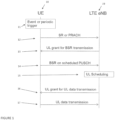
- FIG. 1 illustrates a typical 3GPP LTE contention free data transmission process as described above.
- the UE 10 due to an event or periodic trigger 11, sends a scheduling request (SR) 12 to the LTE eNB 19.
- the eNB 19 returns an uplink (UL) grant for buffer status report (BSR) transmission 13.
- the UE 10 performs at step 14 a BSR on a physical uplink shared channel (PUSCH).
- the eNB 19 performs the uplink (UL) scheduling for the UE 10.
- the UL grant is sent to the UE 10 at step 16.
- the UE 10 performs the UL data transmission at step 17. It can be observed that this kind of process not only includes high latency, but also much DL/UL control channel overhead.
- a resource pool further contains multiple resource units, each of which can contain at least one physical resource block.
- UE needs to know the resource units within the allocated resource pool for UL data transmission. It is desirable to have different UEs have different starting resource unit in the resource pool as much as possible so that the collision probability can be reduced.
- TBS TB size
- the example embodiments of the invention work to address at least these issues associated with contention based operations.
- the eNB For contention based UL data transmission, the eNB allocates the UL resources for data transmission to a UE without knowing the amount of data and the actual time when data transmission happens. Since there are less UL resources than number of UE, the same UL resources are shared by/allocated to several UE which may start to use the same UL resources at the same time independent from each other. UL resources are based on "timeslots" and/or frequencies. Collision probability should be reduced/minimized to improve UL throughput.
- a wireless access network 9 is adapted for communication between a user equipment UE 10 and a network node NN 12 or other access node of an access network.
- the NN 12 can be any network device e.g., a base station that is part of or separate from the network 9.
- the network 9 may include or may use a higher controlling node (not shown, by non-limiting example a gateway GW, a user plane entity UPE, a mobility management entity MME, or a system architecture evolution gateway SAE-GW) for operations in accordance with the example embodiments.
- a higher controlling node may be accessible via any communication link, including the antenna 10E and/or 12E, and/or via Internet 14.
- the UE 10 includes a data processor (DP) 10A, a memory (MEM) 10B that stores a program (PROG) 10C, and a suitable radio frequency (RF) transmitter and receiver 10D coupled to one or more antennas 10E for bidirectional wireless communications over a data link 11 with the NN 12.
- the NN 12 also includes a DP 12A, a MEM 12B that stores a PROG 12C, and a suitable RF transmitter and receiver 12D coupled to one or more antennas 12E.
- the NN 12 may be coupled via a data link 13 to the internet or other broader communication network.
- resource processors 10F, 12F respectively, for defining and configuring resource sets in accordance with the example embodiments of the invention as described herein.
- At least one of the PROGs 10C and 12C is assumed to include program instructions that, when executed by the associated DP, enable the electronic device to operate in accordance with the example embodiments of this invention as described in detail below.
- an apparatus (such as the NN 12 of Figure 2 ) comprising: means for configuring (DP 12A, DP 12F, PROG 12C, and/or MEM 12B of Figure 2 ) a resource pool for a plurality of user equipment configured with contention based transmission; means for configuring (DP 12A, DP 12F, PROG 12C, and MEM 12B of Figure 2 ) a resource allocation within the resource pool for a contention based transmission by user equipment of the plurality of user equipment configured for contention based transmissions, wherein the resource allocation is configured with more than one predefined or preconfigured sets of resource allocation granularities; and means for sending (Antenna 12E, transmitter/receiver 12D of Figure 2 ) information comprising the resource allocation towards the user equipment, wherein the information comprises an indication of a set of the predefined or preconfigured sets of the resource allocation granularities that the user equipment is to use for the contention based transmission.
- an apparatus (such as the UE 10 of Figure 2 ) comprising: means for receiving (Antenna 10E, transmitter/receiver 10D of Figure 2 ) from a network device information of resources allocated for a contention based transmission by the apparatus, wherein the resource allocation is configured with more than one predefined or preconfigured sets of resource allocation granularities, and wherein the information comprises an indication of a set of the predefined or preconfigured sets of the resource allocation granularities that the apparatus is to use for the contention based transmission; means, based on the information, for identifying (DP 10A, DP 10F, PROG 10C, and/or MEM 10B of Figure 2 ) the set of the predefined or preconfigured sets of the resource allocation granularities that the apparatus is to use for the contention based transmission; and means for performing (Antenna 10E, transmitter/receiver 10D, DP 10A, DP 10F, PROG 10C, and MEM 10B of
- the example embodiments of this invention may be implemented by computer software executable by the DP 10A of the UE 10 and by the DP12A of the NN 12, or other DPs, or by hardware, or by a combination of software and/or firmware and hardware.
- the interactions between the major logical elements should be obvious to those skilled in the art for the level of detail needed to gain an understanding of the broader aspects of the invention beyond only the specific examples herein.
- the invention may be implemented with an application specific integrated circuit ASIC, a field programmable gated array FPGA, a digital signal processor or other suitable processor to carry out the intended function of the invention, including a central processor, a random access memory RAM, read only memory ROM, and communication ports for communicating between the NN 12 and the UE 10 as detailed above.
- ASIC application specific integrated circuit
- FPGA field programmable gated array
- ROM read only memory
- communication ports for communicating between the NN 12 and the UE 10 as detailed above.
- the various embodiments of the UE 10 can include, but are not limited to, cellular telephones, personal digital assistants (PDAs) having wireless communication capabilities, portable computers having wireless communication capabilities, image capture devices such as digital cameras having wireless communication capabilities, gaming devices having wireless communication capabilities, music storage and playback appliances having wireless communication capabilities, Internet appliances permitting wireless Internet access and browsing, as well as portable units or terminals that incorporate combinations of such functions.
- PDAs personal digital assistants
- portable computers having wireless communication capabilities
- image capture devices such as digital cameras having wireless communication capabilities
- gaming devices having wireless communication capabilities
- music storage and playback appliances having wireless communication capabilities
- Internet appliances permitting wireless Internet access and browsing, as well as portable units or terminals that incorporate combinations of such functions.
- the MEMs 10B and 12B may be of any type suitable to the local technical environment and may be implemented using any suitable data storage technology, such as semiconductor based memory devices, magnetic memory devices and systems, optical memory devices and systems, fixed memory and removable memory.
- the DPs 10A and 12A may be of any type suitable to the local technical environment, and may include one or more of general purpose computers, special purpose computers, microprocessors, digital signal processors (DSPs) and processors based on a multi-core processor architecture, as non-limiting examples.
- At least one of the memories is assumed to tangibly embody software program instructions that, when executed by the associated processor, enable the electronic device to operate in accordance with the example embodiments of this invention, as detailed by example above.
- the example embodiments of this invention may be implemented at least in part by computer software executable by the controller/DP of the UE 10 or the NN 12 by hardware, or by a combination of software and hardware.
- Hybrid automatic repeat request is a combination of high-rate forward error-correcting coding and ARQ error-control.
- standard ARQ redundant bits are added to data to be transmitted using an error-detecting (ED) code such as a cyclic redundancy check (CRC).
- ED error-detecting
- CRC cyclic redundancy check
- Receivers detecting a corrupted message will request a new message from the sender.
- eNB for one packet that is transmitted by multiple TBs and multiple HARQ processes, it is desirable to have eNB know the HARQ process ID in order to do soft information combining.
- the HARQ process ID can be of course explicitly indicated but this requires more UL overhead and even new UL channel to carry such indication. Further, as similarly stated above, it is desirable to have different UEs have different starting position as much as possible so that the collision probability can be reduced.
- a CB-PUSCH starting RU for a HARQ process can be determined from CB-PUSCH transmission granularities information, e.g., dependent on maximum granularity.
- each of the granularities contain at least one predefined number of RU so a network node, such as an eNB, would configure one set of granularities to CB UEs that are allocated with same set of resources.
- the configuration of the granularities can be based on e.g., the number of CB UEs on the indicated resources. Typically, if there are limited number of CB UEs allocated with certain resources, the configured granularities can be much higher. In that sense, the configured granularities could be common for all CB UEs, and the configuration can be transmitted through broadcast signaling.
- UE can choose either 1, 2, 4, 8 or 16 RUs for CB-PUSCH transmission according to the TBS, preferably according to the most suitable RU determination.
- the network node or eNB can indicate a set by indicating a set index, or indicate the maximum granularity. Further, the UE can determine other granularities implicitly. For example, in situations when predefined sets of granularities are defined e.g., as discussed above, and if the UE is indicated a granularity with 16, then UE can know that the set of granularities is ⁇ 1,2,4,8,16 ⁇ i.e., the set includes additionally smaller granularities, e.g., determined by dividing by 2 or another number.
- the network node or eNB might configure different set of granularities for the initial transmission and for the retransmission.
- a network node or eNB can detect each possible transmission granularity through blind detection.
- One kind of blind detection could be for example an eNB tries one decoding for each granularity.
- the other example is that the eNB detects the accumulated power for each granularity.
- the UE can determine a starting RU for CB-PUSCH transmission based on at least HARQ process ID and/or an UE identifier. After receiving the information identifying the available resources and the set of transmission granularities, the UE can determine the starting RU and the resources to transmit a certain TB. Other parameters for starting RU decision processes could be based on a maximum configured granularity. The starting RU could be the same for each granularity so that on eNB side blind decoding effort can be relaxed, since the soft bit information calculated for the lower granularity can be reused for decoding for higher granularity. In accordance with an example embodiment, the granularity which is used for CB-PUSCH is decided by the TBS.
- the UE can determine a reference starting RU according to a higher layer configuration and decide the starting RU for each HARQ process according to a configured offset (in terms of RUs) between HARQ processes. Having a different starting RU for each HARQ process enables the eNB to know the HARQ process ID implicitly after successful decoding the CB-PUSCH.
- a network node or an eNB can configure a certain number of HARQ processes to CB UEs through broadcast signaling in order to balance the collision probability and the achieved throughput.
- the network node or eNB need to determine which set of granularities it should configure to each UE. This can be based on e.g., the number of CB UEs on the indicated resources. Typically if there are limited number of CB UEs with certain indicated resources, the configured granularities can be much higher.
- the configurations from eNB to UE include:
- the UE After UE got the configurations from eNB, the UE would decide the starting RU based on HARQ process ID and/or its identifier, for example C-RNTI.
- One function for the starting RU determination could be:
- the UE can determine the starting RU for CB-PUSCH transmission based on at least HARQ process ID and/or UE-ID.
- the resource units selected by two or more different UEs are fully or partially overlapped.
- two UEs are using the same starting RU but with different transmission granularity.
- it could be based on the network node or eNB implementation on how to detect signals from different UEs.
- the eNB can use a successive interference cancellation algorithm, by which eNB firstly detects the strongly signals, and remove it from the received signals in the overlapped resources, then detects the weaker signal.
- the eNB can configure a certain number of HARQ processes to CB UEs through broadcast signaling in order to balance the collision probability and the achieved throughput.
- FIG. 3 One example is illustrated in Figure 3 , where the available RUs for CB-PUSCH are the ones not used for legacy PUSCH transmission. These RUs are re-numbered to generate sequential virtual RUs. In one embodiment, RU interleaving can be operated before the numbering.
- UE is configured with a granularity set 11, 2, 4, 8 ⁇ RUs. The starting RUs for HARQ process 1 and HARQ process 2 are illustrated.
- FIG. 3 there is shown granularity sets configured for HARQ processes in accordance with the example embodiments.
- the resource units used for CB-PUSCH form a resource pool 340.
- the resource units for CB-PUSCH are renumbered to generate sequential virtual RUs in accordance with the defined granularities such that at least some of the granularities can be used for CB-PUSCH for each UE.
- the granularities are sent to a UE, such as the UE 10 of Figure 2 .
- the granularities are sent to UEs which are configured to use the same resource pool for their contention based signalling.
- the granularity set can include multiple resource units, based on network node or eNB configuration.
- one UL packet from a specific UE is segmented to be two transport blocks, corresponding to two HARQ processes, HARQ process 1 and HARQ process 2, respectively.
- the starting RU for each HARQ process is determined by at least the HARQ process ID and/or UE ID.
- this offset can be preconfigured by the network node or eNB.
- the UE is configured with a granularity set 320 and 330 for each HARQ process, which contains ⁇ 1,2,4,8 ⁇ resource units, as shown in 350.
- the starting resource unit for each granularity is same, as in 390.
- the available resource units for HARQ process 1 and HARQ process 2 are shown in 361 and 362, respectively.
- UE selects 4 resource units out of the available resource units 361, 362 to transmit CB-PUSCH for each HARQ process, based on the CB-PUSCH TBS. The rest of the available resource units might be used for transmitting CB-PUSCH for other UEs.
- a resource pool 340 for a plurality of user equipment configured with contention based transmission configures a resource allocation 361, 362 within the resource pool 340 for a contention based transmission by a user equipment of the plurality of user equipment configured for contention based transmissions, wherein the resource allocation 361, 362 is configured with more than one predefined or preconfigured sets 330, 320 of resource allocation granularities 350; and send information 420 comprising the resource allocation 361, 362 towards the user equipment, wherein the information comprises an indication of a set 370 of the predefined or preconfigured sets 320, 330 of the resource allocation granularities 350 that the user equipment is to use for the contention based transmission 390.
- Figure 4a illustrates operations which may be performed by a network device such as, but not limited to, a network node NN 12 as in Figure 2 or an eNB.
- a network device such as, but not limited to, a network node NN 12 as in Figure 2 or an eNB.
- step 410 there is configuring a resource pool for a plurality of user equipment configured with contention based transmission.
- step 420 there is configuring a resource allocation within the resource pool for a contention based transmission by a user equipment of the plurality of user equipment configured for contention based transmissions, wherein the resource allocation is configured with more than one predefined or preconfigured sets of resource allocation granularities.
- the information comprises an indication of a set of the predefined or preconfigured sets of the resource allocation granularities that the user equipment is to use for the contention based transmission.
- the indication of the set of the predefined or preconfigured sets of the resource allocation that the user equipment is to use comprises at least one of a set index and a maximum granularity of the set the user equipment is to use for the contention based transmission.
- the configured resource pool comprises at least one physical resource unit, and interleaving and re-numbering the physical resource units to generate sequential virtual physical resource units.
- each of the predefined or preconfigured sets of resource allocation granularities comprises a different number of physical resource units.
- each of the physical resource units contain at least one physical resource block.
- the information comprises a hybrid automatic repeat request process configuration for at least one user equipment of the plurality of user equipment, and wherein a resource unit offset is configured between the hybrid automatic repeat processes.
- the set of the predefined or preconfigured sets of the resource allocation granularities that the user equipment is to use for the contention based transmission are different for different hybrid automatic repeat processes.
- a starting physical resource unit of at least one starting physical resource unit of the configured resource pool that the user equipment is to use for contention based transmission is based on at least one of a hybrid automatic repeat request process ID and a UE identifier such as a cell-radio network temporary identifier associated with the user equipment.
- the starting physical resource unit is same for the indicated set of resource allocation granularities.
- an amount of the more than one predefined or preconfigured sets of resource allocation granularities is based on an amount of the plurality of user equipment configured for contention based transmissions.
- the configuration of the more than one predefined or preconfigured sets of resource allocation granularities may be provided to the user equipment via any kind of signaling indication e.g., the configuration is sent through broadcasting signaling, or through the user equipment specific higher layer signaling or through the group user equipment specific higher layer signaling, or through the user equipment specific physical layer signaling or through the group user equipment specific physical layer signaling.
- Group user specific signaling means that multiple UEs are grouped together and an eNB would send one signaling indication to all UEs in the same group.
- the benefit of physical layer signaling is "fast" propagation and "fast” feedback response, but has higher signaling overhead, while the benefit of higher layer signaling is lower signaling overhead, but is “slow” compared to physical layer signaling.
- the indication of the set of the predefined or preconfigured sets of the resource allocation granularities is through broadcasting signaling, or UE specific or group UE specific higher layer signaling, or UE specific or group UE specific physical layer signaling.
- a non-transitory computer-readable medium (MEM 12B of Figure 2 ) storing program code (PROG 12C of Figure 2 ), the program code executed by at least one processor (DP 12A and/or DP 12F of Figure 2 ) to perform the operations as at least described in the paragraphs above.
- an apparatus comprising: means for configuring (DP 12A, DP 12F, PROG 12C, and MEM 12B of Figure 2 ) a resource pool for a plurality of user equipment configured with contention based transmission.
- Attenna 12E transmitter/receiver 12D of Figure 2
- information comprising the resource allocation towards the user equipment [UE 10]
- the information comprises an indication of a set of the predefined or preconfigured sets of the resource allocation granularities that the user equipment is to use for the contention based transmission.
- At least the means for configuring and sending comprises a non-transitory computer readable medium [MEM 12B] encoded with a computer program [PROG 12C] executable by at least one processor [DP 12A and/or 12F].
- Figure 4b illustrates operations which may be performed by a device such as, but not limited to, a device (e.g., the UE 10 as in Fig. 2 ).
- a device e.g., the UE 10 as in Fig. 2
- the resource allocation is configured with more than one predefined or preconfigured sets of resource allocation granularities
- the information comprises an indication of a set of the predefined or preconfigured sets of the resource allocation granularities that the apparatus is to use for the contention based transmission.
- step 460 of Figure 4b there is, based on the information, identifying the set of the predefined or preconfigured sets of the resource allocation granularities that the apparatus is to use for the contention based transmission. Then as shown in step 470 the contention based transmission is performed using the identified set of the resource allocation granularities.
- the indication of the set of the predefined or preconfigured sets of the resource allocation granularities that the apparatus is to use comprises at least one of a set index and a maximum granularity of the set to use for the contention based transmission.
- the configured resource pool comprises at least one physical resource unit, and interleaving and re-numbering the physical resource units to generate sequential virtual physical resource units.
- each of the predefined or preconfigured sets of resource allocation granularities comprises a different number of physical resource units.
- the UE can determine a reference starting RU according to a higher layer configuration and decide the starting RU for each HARQ process according to a configured offset (in terms of RUs) between HARQ processes.
- a starting physical resource unit of at least one starting physical resource unit of the configured resource pool that the user equipment is to use for contention based transmission is based on at least one of a hybrid automatic repeat request process ID and a UE identifier such as a cell-radio network temporary identifier associated with the user equipment e.g., as described in UE operations above
- the starting physical resource unit is same for the indicated set of resource allocation granularities. This can relax eNB side blind decoding effort, since the soft bit information calculated for the lower granularity can be reused for decoding for higher granularity.
- the configuration of the more than one sets of resource allocation granularities is received through broadcasting signaling, or the user equipment specific or group user equipment specific higher layer signaling, or the user equipment specific or group user equipment specific physical layer signaling.
- the indication of the set of the predefined or preconfigured sets of the resource allocation granularities is through the broadcasting signaling, or the UE specific or group UE specific higher layer signaling, or the UE specific or group UE specific physical layer signaling.
- a non-transitory computer-readable medium (MEM 12B of Figure 2 ) storing program code (PROG 10C of Figure 2 ), the program code executed by at least one processor (DP 10A and/or DP 10F of Figure 2 ) to perform the operations as at least described in the paragraphs above.
- an apparatus comprising: means for receiving (Antenna 10E, transmitter/receiver 10D of Figure 2 ) from a network device [NN 12 of Fig. 2 or eNB], information of resources allocated for a contention based transmission by the apparatus [e.g., UE 10 of Fig. 2 ], wherein the resource allocation is configured with more than one predefined or preconfigured sets of resource allocation granularities, and wherein the information comprises an indication of a set of the predefined sets of the resource allocation granularities that the apparatus is to use for the contention based transmission.
- At least the means for receiving, identifying, configuring, and performing comprises a non-transitory computer readable medium [MEM 10B] encoded with a computer program [PROG 10C] executable by at least one processor [DP 10A and/or 10F].
- the benefit of flexible resource allocation by selecting the most suitable transmission granularity from a set results in improved UL throughput. If the packet size is very small, UE will select a smallest transmission granularity; the rest of resources can be used by other UEs. Further, the benefits of the operations in accordance with the example embodiments include achieving randomized starting positions among UEs which may be determined based on UE ID, process ID, and/or the flexible resource granularity, and which can lead to a low collision probability.
- the various embodiments may be implemented in hardware or special purpose circuits, software, logic or any combination thereof.
- some aspects may be implemented in hardware, while other aspects may be implemented in firmware or software which may be executed by a controller, microprocessor or other computing device, although the invention is not limited thereto.
- firmware or software which may be executed by a controller, microprocessor or other computing device, although the invention is not limited thereto.
- While various aspects of the invention may be illustrated and described as block diagrams, flow charts, or using some other pictorial representation, it is well understood that these blocks, apparatus, systems, techniques or methods described herein may be implemented in, as non-limiting examples, hardware, software, firmware, special purpose circuits or logic, general purpose hardware or controller or other computing devices, or some combination thereof.
- Embodiments of the inventions may be practiced in various components such as integrated circuit modules.
- the design of integrated circuits is by and large a highly automated process.
- Complex and powerful software tools are available for converting a logic level design into a semiconductor circuit design ready to be etched and formed on a semiconductor substrate.
- connection means any connection or coupling, either direct or indirect, between two or more elements, and may encompass the presence of one or more intermediate elements between two elements that are “connected” or “coupled” together.
- the coupling or connection between the elements can be physical, logical, or a combination thereof.
- two elements may be considered to be “connected” or “coupled” together by the use of one or more wires, cables and/or printed electrical connections, as well as by the use of electromagnetic energy, such as electromagnetic energy having wavelengths in the radio frequency region, the microwave region and the optical (both visible and invisible) region, as several non-limiting and non-exhaustive examples.
Landscapes
- Engineering & Computer Science (AREA)
- Signal Processing (AREA)
- Computer Networks & Wireless Communication (AREA)
- Mobile Radio Communication Systems (AREA)
Claims (13)
- Verfahren, das von einer Netzwerkvorrichtung durchgeführt wird und Folgendes umfasst:Auslegen (410) eines Ressourcenpools für eine Vielzahl von Teilnehmereinrichtungen, die mit einer konfliktbasierten Übertragung ausgelegt sind;Auslegen (420) einer Ressourcenzuteilung im Ressourcenpool für eine konfliktbasierte Übertragung durch eine Teilnehmereinrichtung der Vielzahl von Teilnehmereinrichtungen, die für konfliktbasierte Übertragungen ausgelegt sind, wobei die Ressourcenzuteilung mit mehr als einem vordefinierten oder vorausgelegten Sätzen von Ressourcenzuteilungsgranularitäten ausgelegt ist, wobei jeder der vordefinierten oder vorausgelegten Sätze von Ressourcenzuteilungsgranularitäten eine Vielzahl von Ressourcenzuteilungswerten umfasst, wobei jeder der Vielzahl von Ressourcenzuteilungswerten eine Anzahl von physischen Ressourceneinheiten anzeigt und wobei jeder der vordefinierten oder vorausgelegten Sätze von Ressourcenzuteilungsgranularitäten eine andere Anzahl von Ressourcenzuteilungswerten umfasst; undSenden (430) von Informationen, die die Ressourcenzuteilung umfassen, an die Teilnehmereinrichtung, wobei die Informationen eine Anzeige eines Satzes der vordefinierten oder vorausgelegten Sätze von Ressourcenzuteilungsgranularitäten umfassen, der von der Teilnehmereinrichtung zu verwenden ist, um einen der Vielzahl von Ressourcenzuteilungswerten auszuwählen, die im angezeigten Satz für die konfliktbasierte Übertragung beinhaltet sind.
- Verfahren nach Anspruch 1, wobei die Anzeige des Satzes der vordefinierten oder vorausgelegten Sätze der Ressourcenzuteilung, der von der Teilnehmereinrichtung zu verwenden ist, mindestens eines von einem Satzindex und einer maximalen Granularität des Satzes umfasst, der von der Teilnehmereinrichtung für die konfliktbasierte Übertragung zu verwenden ist.
- Verfahren nach Anspruch 2, wobei eine physische Startressourceneinheit von mindestens einer physischen Startressourceneinheit des ausgelegten Ressourcenpools, die von der Teilnehmereinrichtung für eine konfliktbasierte Übertragung zu verwenden ist, auf mindestens einem von einer ID eines hybriden automatischen Wiederholungsanforderungsprozesses und einer temporären Kennung eines Mobilfunknetzwerks, die mit der Teilnehmereinrichtung verknüpft ist, umfasst.
- Verfahren nach Anspruch 3, wobei die physische Startressourceneinheit für den angezeigten Satz von Ressourcenzuteilungsgranularitäten eine selbe ist.
- Verfahren nach Anspruch 3, wobei die Informationen eine Auslegung für einen hybriden automatischen Wiederholungsanforderungsprozess für mindestens eine Teilnehmereinrichtung der Vielzahl von Teilnehmereinrichtungen umfassen und wobei zwischen den hybriden automatischen Wiederholungsprozessen ein Ressourceneinheitsversatz ausgelegt ist.
- Verfahren nach Anspruch 1, wobei eine Menge der mehr als ein vordefinierten oder vorausgelegten Sätze von Ressourcenzuteilungsgranularitäten auf einer Menge der Vielzahl von Teilnehmereinrichtungen basiert, die für konfliktbasierte Übertragungen ausgelegt sind.
- Netzwerkvorrichtung, die Folgendes umfasst:Mittel zum Auslegen eines Ressourcenpools für eine Vielzahl von Teilnehmereinrichtungen, die mit einer konfliktbasierten Übertragung ausgelegt sind;Mittel zum Auslegen einer Ressourcenzuteilung im Ressourcenpool für eine konfliktbasierte Übertragung durch eine Teilnehmereinrichtung der Vielzahl von Teilnehmereinrichtungen, die für konfliktbasierte Übertragungen ausgelegt sind, wobei die Ressourcenzuteilung mit mehr als einem vordefinierten oder vorausgelegten Sätzen von Ressourcenzuteilungsgranularitäten ausgelegt ist, wobei jeder der vordefinierten oder vorausgelegten Sätze von Ressourcenzuteilungsgranularitäten eine Vielzahl von Ressourcenzuteilungswerten umfasst, wobei jeder der Vielzahl von Ressourcenzuteilungswerten eine Anzahl von physischen Ressourceneinheiten anzeigt und wobei jeder der vordefinierten oder vorausgelegten Sätze von Ressourcenzuteilungsgranularitäten eine andere Anzahl von Ressourcenzuteilungswerten umfasst; undMittel zum Senden von Informationen, die die Ressourcenzuteilung umfassen, an die Teilnehmereinrichtung, wobei die Informationen eine Anzeige eines Satzes der vordefinierten oder vorausgelegten Sätze von Ressourcenzuteilungsgranularitäten umfassen, der von der Teilnehmereinrichtung zu verwenden ist, um einen der Vielzahl von Ressourcenzuteilungswerten auszuwählen, die im angezeigten Satz für die konfliktbasierte Übertragung beinhaltet sind.
- Verfahren, das von einer Teilnehmereinrichtung durchgeführt wird und Folgendes umfasst:Empfangen (450) von Informationen einer Ressourcenzuteilung, die für eine konfliktbasierte Übertragung durch die Teilnehmereinrichtung ausgelegt ist, von einer Netzwerkvorrichtung, wobei die Ressourcenzuteilung innerhalb eines Ressourcenpools liegt, der für eine Vielzahl von Teilnehmereinrichtungen ausgelegt ist, die mit konfliktbasierten Übertragungen ausgelegt sind,wobei die Ressourcenzuteilung mit mehr als einem vordefinierten oder vorausgelegten Sätzen von Ressourcenzuteilungsgranularitäten ausgelegt ist und wobei die Informationen eine Anzeige eines Satzes der vordefinierten oder vorausgelegten Sätze der Ressourcenzuteilungsgranularitäten umfassen, der von der Teilnehmereinrichtung für die konfliktbasierte Übertragung zu verwenden ist, wobei jeder der vordefinierten oder vorausgelegten Sätze von Ressourcenzuteilungsgranularitäten eine Vielzahl von Ressourcenzuteilungswerten umfasst, wobei jeder der Vielzahl von Ressourcenzuteilungswerten eine Anzahl von physischen Ressourceneinheiten anzeigt und wobei jeder der vordefinierten oder vorausgelegten Sätze von Ressourcenzuteilungsgranularitäten eine andere Anzahl von Ressourcenzuteilungswerten umfasst;Identifizieren (460) des Satzes der vordefinierten oder vorausgelegten Sätze der Ressourcenzuteilungsgranularitäten, der von der Teilnehmereinrichtung für die konfliktbasierte Übertragung zu verwenden ist, und Auswählen von einem der Vielzahl von Ressourcenzuteilungswerten, die im angezeigten Satz beinhaltet sind, auf Basis der Informationen; undDurchführen (470) der konfliktbasierten Übertragung unter Verwendung des ausgewählten Ressourcenzuteilungswertes.
- Verfahren nach Anspruch 8, wobei die Anzeige des Satzes der vordefinierten oder vorausgelegten Sätze der Ressourcenzuteilungsgranularitäten, der von der Teilnehmereinrichtung zu verwenden ist, mindestens eines von einem Satzindex und einer maximalen Granularität des Satzes umfasst, der für die konfliktbasierte Übertragung zu verwenden ist.
- Verfahren nach einem der Ansprüche 8 oder 9, wobei der ausgelegte Ressourcenpool mindestens eine physische Ressourceneinheit sowie das Verschachteln und erneute Nummerieren der physischen Ressourceneinheiten umfasst, um sequenzielle virtuelle physische Ressourceneinheiten zu erzeugen.
- Verfahren nach einem der Ansprüche 8 oder 9, wobei die Teilnehmereinrichtung eine Referenzstartressourceneinheit gemäß einer Auslegung einer höheren Schicht und eine Startressourceneinheit für jeden hybriden automatischen Wiederholungsanforderungsprozess gemäß einem ausgelegten Versatz von Ressourceneinheiten zwischen hybriden automatischen Wiederholungsanforderungsprozessen bestimmen kann.
- Nichttransitorisches computerlesbares Medium, auf dem ein Programmcode gespeichert ist, wobei der Programmcode von mindestens einem Prozessor ausgeführt wird, um das Verfahren von einem der Ansprüche 1 bis 6, 8 bis 11 durchzuführen.
- Teilnehmereinrichtung, die Folgendes umfasst:Mittel zum Empfangen einer Ressourcenzuteilung, die für eine konfliktbasierte Übertragung durch die Teilnehmereinrichtung ausgelegt ist, von einer Netzwerkvorrichtung, wobei die Ressourcenzuteilung innerhalb eines Ressourcenpools liegt, der für eine Vielzahl von Teilnehmereinrichtungen ausgelegt ist, die mit konfliktbasierten Übertragungen ausgelegt sind, wobei die Ressourcenzuteilung mit mehr als einem vordefinierten oder vorausgelegten Sätzen von Ressourcenzuteilungsgranularitäten ausgelegt ist und wobei die Informationen eine Anzeige eines Satzes der vordefinierten oder vorausgelegten Sätze der Ressourcenzuteilungsgranularitäten umfassen, der von der Teilnehmereinrichtung für die konfliktbasierte Übertragung zu verwenden ist, wobei jeder der vordefinierten oder vorausgelegten Sätze von Ressourcenzuteilungsgranularitäten eine Vielzahl von Ressourcenzuteilungswerten umfasst, wobei jeder der Vielzahl von Ressourcenzuteilungswerten eine Anzahl von physischen Ressourceneinheiten anzeigt und wobei jeder der vordefinierten oder vorausgelegten Sätze von Ressourcenzuteilungsgranularitäten eine andere Anzahl von Ressourcenzuteilungswerten umfasst;Mittel zum Identifizieren des Satzes der vordefinierten oder vorausgelegten Sätze der Ressourcenzuteilungsgranularitäten, der von der Teilnehmereinrichtung für die konfliktbasierte Übertragung zu verwenden ist, und zum Auswählen von einem der Vielzahl von Ressourcenzuteilungswerten, die im angezeigten Satz beinhaltet sind, auf Basis der Informationen; undMittel zum Durchführen der konfliktbasierten Übertragung unter Verwendung des ausgewählten Ressourcenzuteilungswertes.
Applications Claiming Priority (1)
| Application Number | Priority Date | Filing Date | Title |
|---|---|---|---|
| PCT/CN2016/085274 WO2017210893A1 (en) | 2016-06-08 | 2016-06-08 | Contention-based uplink data transmission |
Publications (3)
| Publication Number | Publication Date |
|---|---|
| EP3469848A1 EP3469848A1 (de) | 2019-04-17 |
| EP3469848A4 EP3469848A4 (de) | 2020-02-19 |
| EP3469848B1 true EP3469848B1 (de) | 2024-09-04 |
Family
ID=60577490
Family Applications (1)
| Application Number | Title | Priority Date | Filing Date |
|---|---|---|---|
| EP16904346.0A Active EP3469848B1 (de) | 2016-06-08 | 2016-06-08 | Konkurrenzbasierte uplink-datenübertragung |
Country Status (4)
| Country | Link |
|---|---|
| US (1) | US10904888B2 (de) |
| EP (1) | EP3469848B1 (de) |
| CN (1) | CN109565883B (de) |
| WO (1) | WO2017210893A1 (de) |
Families Citing this family (3)
| Publication number | Priority date | Publication date | Assignee | Title |
|---|---|---|---|---|
| EP3522428B1 (de) * | 2016-09-29 | 2021-08-04 | LG Electronics Inc. | Verfahren und vorrichtung zum senden und empfangen eines drahtlosen signals in einem drahtloskommunikationssystem |
| CN113678480B (zh) * | 2019-04-30 | 2024-05-14 | 富士通株式会社 | 边链路数据的发送和接收方法以及装置 |
| CN114365526B (zh) * | 2020-07-31 | 2024-12-13 | 上海诺基亚贝尔股份有限公司 | 能量检测阈值的适配 |
Family Cites Families (12)
| Publication number | Priority date | Publication date | Assignee | Title |
|---|---|---|---|---|
| CN100426800C (zh) | 2006-07-20 | 2008-10-15 | 华为技术有限公司 | 一种带宽资源分配的方法 |
| JP4976543B2 (ja) * | 2007-04-27 | 2012-07-18 | エルジー エレクトロニクス インコーポレイティド | 移動通信システムにおいて下り制御チャネルを伝送する方法並びにブロックインターリーバを用いて制御チャネルを物理リソースにマッピングする方法 |
| WO2010124440A1 (zh) * | 2009-04-27 | 2010-11-04 | 华为技术有限公司 | 一种随机接入竞争解决的判断方法、装置和系统 |
| KR20120113698A (ko) | 2009-12-03 | 2012-10-15 | 엘지전자 주식회사 | 무선 통신 시스템에서 효율적인 경합 기반 전송 방법 및 장치 |
| CA2786083C (en) * | 2009-12-31 | 2015-08-25 | Huawei Technologies Co., Ltd. | Contention based resource configuration method and apparatus |
| CN102123399B (zh) * | 2010-01-08 | 2014-01-01 | 华为技术有限公司 | 调度请求的方法及装置 |
| KR20140011820A (ko) * | 2012-07-20 | 2014-01-29 | 삼성전자주식회사 | 무선 통신 시스템에서 제어 정보 송/수신 방법 및 장치 |
| CN104039013B (zh) | 2013-03-06 | 2019-05-17 | 中兴通讯股份有限公司 | 资源分配信息处理方法及装置 |
| US9306721B2 (en) * | 2013-03-15 | 2016-04-05 | Google Technology Holdings LLC | Method and apparatus for device-to-device communication |
| US10123340B2 (en) * | 2013-05-24 | 2018-11-06 | Lg Electronics Inc. | Method for performing measurement in wireless communication system and apparatus therefor |
| EP3043615B1 (de) * | 2013-09-16 | 2018-06-20 | Huawei Technologies Co., Ltd. | Verfahren, benutzervorrichtung und basisstation zur vorbestimmung einer ressource bei direktzugriff |
| JP6346958B2 (ja) | 2014-02-16 | 2018-06-20 | エルジー エレクトロニクス インコーポレイティド | 無線通信システムにおけるアップリンクデータ転送方法及びそのための装置 |
-
2016
- 2016-06-08 US US16/307,732 patent/US10904888B2/en active Active
- 2016-06-08 CN CN201680088126.6A patent/CN109565883B/zh active Active
- 2016-06-08 EP EP16904346.0A patent/EP3469848B1/de active Active
- 2016-06-08 WO PCT/CN2016/085274 patent/WO2017210893A1/en not_active Ceased
Also Published As
| Publication number | Publication date |
|---|---|
| US10904888B2 (en) | 2021-01-26 |
| EP3469848A1 (de) | 2019-04-17 |
| CN109565883B (zh) | 2023-01-13 |
| WO2017210893A1 (en) | 2017-12-14 |
| US20190215822A1 (en) | 2019-07-11 |
| EP3469848A4 (de) | 2020-02-19 |
| CN109565883A (zh) | 2019-04-02 |
Similar Documents
| Publication | Publication Date | Title |
|---|---|---|
| US11576199B2 (en) | Systems and methods for grant-free uplink transmissions | |
| EP3506705B1 (de) | System und verfahren zur übertragung in autorisierungsfreiem uplink-übertragungsschema | |
| EP2206268B1 (de) | Verbesserte weiterübertragungsfähigkeit bei der semipersistenten übertragung | |
| EP3078145B1 (de) | Verfahren für verbesserten harq-mechanismus | |
| CN106211345B (zh) | 上行控制信号的发送方法及装置 | |
| EP2995147B1 (de) | Kompaktes dci für maschinenartigen kommunikationen | |
| EP3304786B1 (de) | Vorrichtung und verfahren zur handhabung der konfiguration von bündelgrössen | |
| CN115884403A (zh) | 数据传输方法、设备及存储介质 | |
| CN116762436A (zh) | 在共享频带中对配置的准许-uci(cg-uci)和上行链路控制信息(uci)进行复用 | |
| EP3614760B1 (de) | Verfahren und vorrichtung zur informationsübertragung | |
| EP2656678A1 (de) | Verfahren und anordnung zur bestätigung von konfliktbasierten uplink-übertragungen in einem telekommunikationssystem | |
| KR20180108035A (ko) | 무선 통신 시스템에서 데이터의 송수신 장치 및 방법 | |
| EP3520282B1 (de) | Infrastrukturausrüstung, drahtlostelekommunikationssystem und verfahren zur bündelung von harq-ack | |
| JP2016220194A (ja) | 無線通信における制御チャネル | |
| EP3469848B1 (de) | Konkurrenzbasierte uplink-datenübertragung | |
| US20180255510A1 (en) | Method to operate a user equipment and method to operate a baseband unit | |
| CN113287365B (zh) | 上行重传指示 | |
| CN108667578A (zh) | 通信方法和通信设备 | |
| KR20210104570A (ko) | 물리적 업링크 제어 채널 충돌을 처리하기 위한 디바이스 및 방법 | |
| CN116982277A (zh) | Harq处理方法、用户设备和基站 | |
| WO2018150084A1 (en) | Efficient and fast data recovery using network coordination information and harq feedback channel |
Legal Events
| Date | Code | Title | Description |
|---|---|---|---|
| STAA | Information on the status of an ep patent application or granted ep patent |
Free format text: STATUS: THE INTERNATIONAL PUBLICATION HAS BEEN MADE |
|
| PUAI | Public reference made under article 153(3) epc to a published international application that has entered the european phase |
Free format text: ORIGINAL CODE: 0009012 |
|
| STAA | Information on the status of an ep patent application or granted ep patent |
Free format text: STATUS: REQUEST FOR EXAMINATION WAS MADE |
|
| 17P | Request for examination filed |
Effective date: 20190108 |
|
| AK | Designated contracting states |
Kind code of ref document: A1 Designated state(s): AL AT BE BG CH CY CZ DE DK EE ES FI FR GB GR HR HU IE IS IT LI LT LU LV MC MK MT NL NO PL PT RO RS SE SI SK SM TR |
|
| AX | Request for extension of the european patent |
Extension state: BA ME |
|
| RAP1 | Party data changed (applicant data changed or rights of an application transferred) |
Owner name: NOKIA TECHNOLOGIES OY |
|
| DAV | Request for validation of the european patent (deleted) | ||
| DAX | Request for extension of the european patent (deleted) | ||
| REG | Reference to a national code |
Ref country code: DE Ref legal event code: R079 Free format text: PREVIOUS MAIN CLASS: H04W0074080000 Ipc: H04L0005000000 Ref country code: DE Ref legal event code: R079 Ref document number: 602016089301 Country of ref document: DE Free format text: PREVIOUS MAIN CLASS: H04W0074080000 Ipc: H04L0005000000 |
|
| A4 | Supplementary search report drawn up and despatched |
Effective date: 20200117 |
|
| RIC1 | Information provided on ipc code assigned before grant |
Ipc: H04W 74/00 20090101ALI20200113BHEP Ipc: H04L 5/00 20060101AFI20200113BHEP Ipc: H04W 74/08 20090101ALI20200113BHEP Ipc: H04L 1/18 20060101ALN20200113BHEP |
|
| STAA | Information on the status of an ep patent application or granted ep patent |
Free format text: STATUS: EXAMINATION IS IN PROGRESS |
|
| 17Q | First examination report despatched |
Effective date: 20210420 |
|
| GRAP | Despatch of communication of intention to grant a patent |
Free format text: ORIGINAL CODE: EPIDOSNIGR1 |
|
| STAA | Information on the status of an ep patent application or granted ep patent |
Free format text: STATUS: GRANT OF PATENT IS INTENDED |
|
| RIC1 | Information provided on ipc code assigned before grant |
Ipc: H04L 1/1822 20230101ALN20240314BHEP Ipc: H04W 74/00 20090101ALI20240314BHEP Ipc: H04W 74/08 20090101ALI20240314BHEP Ipc: H04L 5/00 20060101AFI20240314BHEP |
|
| INTG | Intention to grant announced |
Effective date: 20240403 |
|
| GRAS | Grant fee paid |
Free format text: ORIGINAL CODE: EPIDOSNIGR3 |
|
| GRAA | (expected) grant |
Free format text: ORIGINAL CODE: 0009210 |
|
| STAA | Information on the status of an ep patent application or granted ep patent |
Free format text: STATUS: THE PATENT HAS BEEN GRANTED |
|
| AK | Designated contracting states |
Kind code of ref document: B1 Designated state(s): AL AT BE BG CH CY CZ DE DK EE ES FI FR GB GR HR HU IE IS IT LI LT LU LV MC MK MT NL NO PL PT RO RS SE SI SK SM TR |
|
| REG | Reference to a national code |
Ref country code: GB Ref legal event code: FG4D |
|
| REG | Reference to a national code |
Ref country code: CH Ref legal event code: EP |
|
| REG | Reference to a national code |
Ref country code: IE Ref legal event code: FG4D |
|
| REG | Reference to a national code |
Ref country code: DE Ref legal event code: R096 Ref document number: 602016089301 Country of ref document: DE |
|
| REG | Reference to a national code |
Ref country code: LT Ref legal event code: MG9D |
|
| REG | Reference to a national code |
Ref country code: NL Ref legal event code: MP Effective date: 20240904 |
|
| PG25 | Lapsed in a contracting state [announced via postgrant information from national office to epo] |
Ref country code: NO Free format text: LAPSE BECAUSE OF FAILURE TO SUBMIT A TRANSLATION OF THE DESCRIPTION OR TO PAY THE FEE WITHIN THE PRESCRIBED TIME-LIMIT Effective date: 20241204 |
|
| PG25 | Lapsed in a contracting state [announced via postgrant information from national office to epo] |
Ref country code: PL Free format text: LAPSE BECAUSE OF FAILURE TO SUBMIT A TRANSLATION OF THE DESCRIPTION OR TO PAY THE FEE WITHIN THE PRESCRIBED TIME-LIMIT Effective date: 20240904 Ref country code: GR Free format text: LAPSE BECAUSE OF FAILURE TO SUBMIT A TRANSLATION OF THE DESCRIPTION OR TO PAY THE FEE WITHIN THE PRESCRIBED TIME-LIMIT Effective date: 20241205 Ref country code: FI Free format text: LAPSE BECAUSE OF FAILURE TO SUBMIT A TRANSLATION OF THE DESCRIPTION OR TO PAY THE FEE WITHIN THE PRESCRIBED TIME-LIMIT Effective date: 20240904 |
|
| PG25 | Lapsed in a contracting state [announced via postgrant information from national office to epo] |
Ref country code: BG Free format text: LAPSE BECAUSE OF FAILURE TO SUBMIT A TRANSLATION OF THE DESCRIPTION OR TO PAY THE FEE WITHIN THE PRESCRIBED TIME-LIMIT Effective date: 20240904 |
|
| PG25 | Lapsed in a contracting state [announced via postgrant information from national office to epo] |
Ref country code: LV Free format text: LAPSE BECAUSE OF FAILURE TO SUBMIT A TRANSLATION OF THE DESCRIPTION OR TO PAY THE FEE WITHIN THE PRESCRIBED TIME-LIMIT Effective date: 20240904 |
|
| PG25 | Lapsed in a contracting state [announced via postgrant information from national office to epo] |
Ref country code: HR Free format text: LAPSE BECAUSE OF FAILURE TO SUBMIT A TRANSLATION OF THE DESCRIPTION OR TO PAY THE FEE WITHIN THE PRESCRIBED TIME-LIMIT Effective date: 20240904 |
|
| PG25 | Lapsed in a contracting state [announced via postgrant information from national office to epo] |
Ref country code: ES Free format text: LAPSE BECAUSE OF FAILURE TO SUBMIT A TRANSLATION OF THE DESCRIPTION OR TO PAY THE FEE WITHIN THE PRESCRIBED TIME-LIMIT Effective date: 20240904 Ref country code: RS Free format text: LAPSE BECAUSE OF FAILURE TO SUBMIT A TRANSLATION OF THE DESCRIPTION OR TO PAY THE FEE WITHIN THE PRESCRIBED TIME-LIMIT Effective date: 20241204 |
|
| PG25 | Lapsed in a contracting state [announced via postgrant information from national office to epo] |
Ref country code: RS Free format text: LAPSE BECAUSE OF FAILURE TO SUBMIT A TRANSLATION OF THE DESCRIPTION OR TO PAY THE FEE WITHIN THE PRESCRIBED TIME-LIMIT Effective date: 20241204 Ref country code: PL Free format text: LAPSE BECAUSE OF FAILURE TO SUBMIT A TRANSLATION OF THE DESCRIPTION OR TO PAY THE FEE WITHIN THE PRESCRIBED TIME-LIMIT Effective date: 20240904 Ref country code: NO Free format text: LAPSE BECAUSE OF FAILURE TO SUBMIT A TRANSLATION OF THE DESCRIPTION OR TO PAY THE FEE WITHIN THE PRESCRIBED TIME-LIMIT Effective date: 20241204 Ref country code: LV Free format text: LAPSE BECAUSE OF FAILURE TO SUBMIT A TRANSLATION OF THE DESCRIPTION OR TO PAY THE FEE WITHIN THE PRESCRIBED TIME-LIMIT Effective date: 20240904 Ref country code: HR Free format text: LAPSE BECAUSE OF FAILURE TO SUBMIT A TRANSLATION OF THE DESCRIPTION OR TO PAY THE FEE WITHIN THE PRESCRIBED TIME-LIMIT Effective date: 20240904 Ref country code: GR Free format text: LAPSE BECAUSE OF FAILURE TO SUBMIT A TRANSLATION OF THE DESCRIPTION OR TO PAY THE FEE WITHIN THE PRESCRIBED TIME-LIMIT Effective date: 20241205 Ref country code: FI Free format text: LAPSE BECAUSE OF FAILURE TO SUBMIT A TRANSLATION OF THE DESCRIPTION OR TO PAY THE FEE WITHIN THE PRESCRIBED TIME-LIMIT Effective date: 20240904 Ref country code: ES Free format text: LAPSE BECAUSE OF FAILURE TO SUBMIT A TRANSLATION OF THE DESCRIPTION OR TO PAY THE FEE WITHIN THE PRESCRIBED TIME-LIMIT Effective date: 20240904 Ref country code: BG Free format text: LAPSE BECAUSE OF FAILURE TO SUBMIT A TRANSLATION OF THE DESCRIPTION OR TO PAY THE FEE WITHIN THE PRESCRIBED TIME-LIMIT Effective date: 20240904 |
|
| REG | Reference to a national code |
Ref country code: AT Ref legal event code: MK05 Ref document number: 1721517 Country of ref document: AT Kind code of ref document: T Effective date: 20240904 |
|
| PG25 | Lapsed in a contracting state [announced via postgrant information from national office to epo] |
Ref country code: NL Free format text: LAPSE BECAUSE OF FAILURE TO SUBMIT A TRANSLATION OF THE DESCRIPTION OR TO PAY THE FEE WITHIN THE PRESCRIBED TIME-LIMIT Effective date: 20240904 |
|
| PG25 | Lapsed in a contracting state [announced via postgrant information from national office to epo] |
Ref country code: IS Free format text: LAPSE BECAUSE OF FAILURE TO SUBMIT A TRANSLATION OF THE DESCRIPTION OR TO PAY THE FEE WITHIN THE PRESCRIBED TIME-LIMIT Effective date: 20250104 Ref country code: PT Free format text: LAPSE BECAUSE OF FAILURE TO SUBMIT A TRANSLATION OF THE DESCRIPTION OR TO PAY THE FEE WITHIN THE PRESCRIBED TIME-LIMIT Effective date: 20250106 |
|
| PG25 | Lapsed in a contracting state [announced via postgrant information from national office to epo] |
Ref country code: RO Free format text: LAPSE BECAUSE OF FAILURE TO SUBMIT A TRANSLATION OF THE DESCRIPTION OR TO PAY THE FEE WITHIN THE PRESCRIBED TIME-LIMIT Effective date: 20240904 Ref country code: SM Free format text: LAPSE BECAUSE OF FAILURE TO SUBMIT A TRANSLATION OF THE DESCRIPTION OR TO PAY THE FEE WITHIN THE PRESCRIBED TIME-LIMIT Effective date: 20240904 |
|
| PG25 | Lapsed in a contracting state [announced via postgrant information from national office to epo] |
Ref country code: EE Free format text: LAPSE BECAUSE OF FAILURE TO SUBMIT A TRANSLATION OF THE DESCRIPTION OR TO PAY THE FEE WITHIN THE PRESCRIBED TIME-LIMIT Effective date: 20240904 Ref country code: AT Free format text: LAPSE BECAUSE OF FAILURE TO SUBMIT A TRANSLATION OF THE DESCRIPTION OR TO PAY THE FEE WITHIN THE PRESCRIBED TIME-LIMIT Effective date: 20240904 |
|
| PG25 | Lapsed in a contracting state [announced via postgrant information from national office to epo] |
Ref country code: CZ Free format text: LAPSE BECAUSE OF FAILURE TO SUBMIT A TRANSLATION OF THE DESCRIPTION OR TO PAY THE FEE WITHIN THE PRESCRIBED TIME-LIMIT Effective date: 20240904 |
|
| PG25 | Lapsed in a contracting state [announced via postgrant information from national office to epo] |
Ref country code: IT Free format text: LAPSE BECAUSE OF FAILURE TO SUBMIT A TRANSLATION OF THE DESCRIPTION OR TO PAY THE FEE WITHIN THE PRESCRIBED TIME-LIMIT Effective date: 20240904 Ref country code: SK Free format text: LAPSE BECAUSE OF FAILURE TO SUBMIT A TRANSLATION OF THE DESCRIPTION OR TO PAY THE FEE WITHIN THE PRESCRIBED TIME-LIMIT Effective date: 20240904 |
|
| REG | Reference to a national code |
Ref country code: DE Ref legal event code: R097 Ref document number: 602016089301 Country of ref document: DE |
|
| PGFP | Annual fee paid to national office [announced via postgrant information from national office to epo] |
Ref country code: DE Payment date: 20250429 Year of fee payment: 10 |
|
| PG25 | Lapsed in a contracting state [announced via postgrant information from national office to epo] |
Ref country code: DK Free format text: LAPSE BECAUSE OF FAILURE TO SUBMIT A TRANSLATION OF THE DESCRIPTION OR TO PAY THE FEE WITHIN THE PRESCRIBED TIME-LIMIT Effective date: 20240904 |
|
| PGFP | Annual fee paid to national office [announced via postgrant information from national office to epo] |
Ref country code: GB Payment date: 20250501 Year of fee payment: 10 |
|
| PLBE | No opposition filed within time limit |
Free format text: ORIGINAL CODE: 0009261 |
|
| STAA | Information on the status of an ep patent application or granted ep patent |
Free format text: STATUS: NO OPPOSITION FILED WITHIN TIME LIMIT |
|
| PGFP | Annual fee paid to national office [announced via postgrant information from national office to epo] |
Ref country code: FR Payment date: 20250508 Year of fee payment: 10 |
|
| 26N | No opposition filed |
Effective date: 20250605 |
|
| PG25 | Lapsed in a contracting state [announced via postgrant information from national office to epo] |
Ref country code: SE Free format text: LAPSE BECAUSE OF FAILURE TO SUBMIT A TRANSLATION OF THE DESCRIPTION OR TO PAY THE FEE WITHIN THE PRESCRIBED TIME-LIMIT Effective date: 20240904 |
|
| REG | Reference to a national code |
Ref country code: CH Ref legal event code: H13 Free format text: ST27 STATUS EVENT CODE: U-0-0-H10-H13 (AS PROVIDED BY THE NATIONAL OFFICE) Effective date: 20260127 |
|
| PG25 | Lapsed in a contracting state [announced via postgrant information from national office to epo] |
Ref country code: MC Free format text: LAPSE BECAUSE OF FAILURE TO SUBMIT A TRANSLATION OF THE DESCRIPTION OR TO PAY THE FEE WITHIN THE PRESCRIBED TIME-LIMIT Effective date: 20240904 |
|
| PG25 | Lapsed in a contracting state [announced via postgrant information from national office to epo] |
Ref country code: LU Free format text: LAPSE BECAUSE OF NON-PAYMENT OF DUE FEES Effective date: 20250608 |
|
| REG | Reference to a national code |
Ref country code: BE Ref legal event code: MM Effective date: 20250630 |
|
| PG25 | Lapsed in a contracting state [announced via postgrant information from national office to epo] |
Ref country code: IE Free format text: LAPSE BECAUSE OF NON-PAYMENT OF DUE FEES Effective date: 20250608 |
|
| PG25 | Lapsed in a contracting state [announced via postgrant information from national office to epo] |
Ref country code: BE Free format text: LAPSE BECAUSE OF NON-PAYMENT OF DUE FEES Effective date: 20250630 |
|
| PG25 | Lapsed in a contracting state [announced via postgrant information from national office to epo] |
Ref country code: CH Free format text: LAPSE BECAUSE OF NON-PAYMENT OF DUE FEES Effective date: 20250630 |