EP3469874B1 - Tête de récolte agricole avec convoyeur à courroie - Google Patents
Tête de récolte agricole avec convoyeur à courroie Download PDFInfo
- Publication number
- EP3469874B1 EP3469874B1 EP18199262.9A EP18199262A EP3469874B1 EP 3469874 B1 EP3469874 B1 EP 3469874B1 EP 18199262 A EP18199262 A EP 18199262A EP 3469874 B1 EP3469874 B1 EP 3469874B1
- Authority
- EP
- European Patent Office
- Prior art keywords
- harvesting head
- agricultural harvesting
- strip
- conveyor
- support
- Prior art date
- Legal status (The legal status is an assumption and is not a legal conclusion. Google has not performed a legal analysis and makes no representation as to the accuracy of the status listed.)
- Active
Links
Images




Classifications
-
- A—HUMAN NECESSITIES
- A01—AGRICULTURE; FORESTRY; ANIMAL HUSBANDRY; HUNTING; TRAPPING; FISHING
- A01D—HARVESTING; MOWING
- A01D61/00—Elevators or conveyors for binders or combines
- A01D61/02—Endless belts
-
- A—HUMAN NECESSITIES
- A01—AGRICULTURE; FORESTRY; ANIMAL HUSBANDRY; HUNTING; TRAPPING; FISHING
- A01D—HARVESTING; MOWING
- A01D41/00—Combines, i.e. harvesters or mowers combined with threshing devices
- A01D41/12—Details of combines
- A01D41/14—Mowing tables
-
- A—HUMAN NECESSITIES
- A01—AGRICULTURE; FORESTRY; ANIMAL HUSBANDRY; HUNTING; TRAPPING; FISHING
- A01D—HARVESTING; MOWING
- A01D57/00—Delivering mechanisms for harvesters or mowers
- A01D57/01—Devices for leading crops to the mowing apparatus
- A01D57/06—Devices for leading crops to the mowing apparatus using endless conveyors
-
- B—PERFORMING OPERATIONS; TRANSPORTING
- B65—CONVEYING; PACKING; STORING; HANDLING THIN OR FILAMENTARY MATERIAL
- B65G—TRANSPORT OR STORAGE DEVICES, e.g. CONVEYORS FOR LOADING OR TIPPING, SHOP CONVEYOR SYSTEMS OR PNEUMATIC TUBE CONVEYORS
- B65G15/00—Conveyors having endless load-conveying surfaces, i.e. belts and like continuous members, to which tractive effort is transmitted by means other than endless driving elements of similar configuration
- B65G15/30—Belts or like endless load-carriers
- B65G15/32—Belts or like endless load-carriers made of rubber or plastics
- B65G15/42—Belts or like endless load-carriers made of rubber or plastics having ribs, ridges, or other surface projections
-
- A—HUMAN NECESSITIES
- A01—AGRICULTURE; FORESTRY; ANIMAL HUSBANDRY; HUNTING; TRAPPING; FISHING
- A01D—HARVESTING; MOWING
- A01D34/00—Mowers; Mowing apparatus of harvesters
- A01D34/01—Mowers; Mowing apparatus of harvesters characterised by features relating to the type of cutting apparatus
- A01D34/02—Mowers; Mowing apparatus of harvesters characterised by features relating to the type of cutting apparatus having reciprocating cutters
- A01D34/13—Cutting apparatus
- A01D34/14—Knife-bars
Definitions
- This invention relates generally to agricultural combines. More particularly it relates to agricultural harvesting heads for mounting on agricultural combines. Even more particularly, it relates to draper headers for agricultural combines.
- Agricultural harvesters are designed to travel through agricultural fields harvesting crops. They include a self-propelled combine vehicle connected to an agricultural harvesting head (also called a "header”) mounted on the front of the combine.
- an agricultural harvesting head also called a "header” mounted on the front of the combine.
- the head is elongate and extends perpendicular to the direction of travel of the combine.
- the function of the agricultural harvesting head is to sever the crop plants from the ground, to carry the cut crop material laterally inward to a central portion of the header, and then to convey the cut crop material rearward through a hole in a central rear wall of the header. Once the cut crop material is passed through the hole, it is received in the combine for further processing.
- the agricultural harvesting head uses two side conveyors (typically auger conveyors or an endless belt conveyors) to draw the material laterally inward from both sides of the harvesting head to a central region of the head.
- a second conveyor then receives the cut crop material and conveys it rearward through the hole in the head.
- the conveyors are endless belt conveyors.
- Each of these conveyors comprise an endless belt that is supported at opposing ends for recirculation about a drive roller and an idler roller.
- the drive roller is mounted close to the center of the header.
- the idler roller is located near an outermost lateral and of the header.
- Cut crop material is deposited on the upper surface of the endless belts of the left side conveyor in the right side conveyor and is carried laterally inward to a central region of the head.
- the endless belt reverses direction as it passes over the drive roller and recirculates back to the idler roller underneath the upper, crop-carrying surface.
- One type of endless belt has cleats that are fixed to the outer surface of the belt. These cleats are approximately 25 mm wide, and extend 25 mm above the surface of the belt. They are made of elastomeric material and extend across the web of the endless belt in a direction perpendicular to the direction of travel of the belt. The web of the endless belt is approximately 1 m wide, and each of the cleats as a length that extends across substantially the entire width of the web of the belt.
- Another solution is to provide a smooth painted metal strip underneath the endless belt in which the metal strip extends from the drive roller to the idler roller.
- the paint is rapidly worn, and the underlying metal surface rusts, thus causing the cleats to wear.
- EP 2 695 510 A1 shown as generic, shows a draper belt platform with a transverse belt support mounted above arms connecting the knife bar to the rear frame part.
- WO 2014/032178 A1 shows another draper belt platform, with a skid plate underneath the returning belt strand, which is also shown in a similar manner in EP 2 422 606 A2 .
- US 5 478 277 A shows a feederhouse with cleat inserts of self-lubricating plastic material.
- An agricultural harvesting head for harvesting crops in an agricultural field is provided, wherein the agricultural harvesting head is configured to be mounted on a combine harvester, the agricultural harvesting head comprising: an elongate frame that extends perpendicular to a direction of travel of the harvesting head as it travels through a field harvesting crops; a rear wall that extends vertically and extends horizontally in a direction parallel to the longitudinal extent of the frame; a conveyor system further comprising a left side conveyor, a right side conveyor, and a center conveyor, wherein the left side conveyor is an endless belt conveyor configured to carry cut crop material laterally from the left end of the frame to a central region of the frame, wherein the right side conveyor is an endless belt conveyor configured to carry cut crop material laterally from the right end of the frame to the central region of the frame, and wherein the center conveyor is disposed to receive cut crop material from both the left side conveyor and the right side conveyor and to carry the cut crop material rearward through a hole in the rear wall; a plurality of support arms extending forward from
- the plastic wear strip may be between 10 and 30 cm wide.
- the plastic wear strip may comprise a high molecular weight thermoplastic material.
- the plastic wear strip may comprise polyethylene or nylon.
- the plastic wear strip may be C-shaped in cross-section.
- the plastic wear strip may comprise a central portion extending across the width of the support strip, a first flange extending downward on one side of the central portion, and a second flange extending downward on the opposite side of the central portion.
- the first flange and the second flange may engage opposing sides of the support strip and thereby together hold the plastic wear strip to the support strip.
- the support strip may be attached to the plurality of support arms with a first plurality of fasteners, and wherein the plastic wear strip is attached to the support strip with a second plurality of fasteners.
- the first plurality of fasteners may comprise threaded fasteners, rivets, or clips.
- the second plurality may comprise threaded fasteners, rivets, or clips.
- the support strip and the plastic wear strip may have the same width.
- the same width may be between 10 and 30 cm.
- an agricultural harvesting head 100 comprises an elongate frame 102 that extends laterally and perpendicular to a direction of travel "V".
- the frame 102 extends substantially the entire width of the head 100.
- the frame 102 is fixed to a vertical rear wall 104 that also extends substantially the entire width of the head 100.
- the frame 102 supports a conveyor system 106 that extends forward from the bottom of the frame 102 and laterally outward, generally perpendicular to the direction of travel "V".
- Conveyor system 106 is an endless belt conveyor system, in which each conveyor of the conveyor system 106 is supported on at least two rollers, including a drive roller and an idler roller. Each drive roller is coupled to a rotary drive motor which drives the drive roller in rotation.
- the conveyor system 106 forms a working floor of head 100.
- Conveyor system 106 includes three conveyors: the left side conveyor 108, right side conveyor 110, and a center conveyor 112. These three conveyors comprise substantially the entire horizontal working surface of the combine between the reciprocating knife 140 and the rear wall 104.
- the left side conveyor 108 includes an endless recirculating belt 114 that is supported at its inner end on a drive roller 116 located adjacent to the center conveyor 112 in the central region of the agricultural harvesting head 100, and is supported at its opposing outer end on a idler roller 117 that is located adjacent to the leftmost end of the agricultural harvesting head 100.
- An endless drive belt 118 is coupled at its inner end to the drive roller 116 to drive the drive roller 116 in rotation.
- the endless drive belt 118 is coupled at its opposing outer end to a drive motor 120 which drives the endless drive belt 118 in rotation.
- the right side conveyor 110 includes an endless recirculating belt 122 that is supported at its inner end on a drive roller 124 located adjacent to the center conveyor 112 in the central region of the agricultural harvesting head 100, and is supported at its opposing outer end on an idler roller 125 that is located adjacent to the rightmost end of the agricultural harvesting head 100.
- An endless drive belt 126 is coupled at its inner end to the drive roller 124 to drive the drive roller 124 in rotation.
- the endless drive belt 126 is coupled at its opposing outer end to a drive motor 128 which drives the endless drive belt 126 in rotation.
- the center conveyor 112 includes an endless recirculating belt 130 that is supported on a drive roller 132 at its rear end, and an idler roller 134 at its front end.
- the drive roller 132 is driven by a drive motor (not shown).
- the drive roller 116 and the drive roller 124 are driven in a direction that draws the upper surface of their respective endless recirculating belts inwardly toward the central region of the agricultural harvesting head 100.
- the left side conveyor 108 and the right side conveyor 110 carry the crop inwardly from the respective left and the right ends of the agricultural harvesting head 100.
- the cut crop material is carried over the top of the drive roller 116 and the drive roller 124 and is deposited upon the endless recirculating belt 130 of the center conveyor 112.
- the drive roller 132 of the center conveyor 112 is driven in a direction that draws the upper surface of the endless recirculating belt 130 in a rearward direction.
- This carries cut crop material deposited upon the center conveyor 112 rearwardly, and underneath a drum conveyor 136.
- the drum conveyor 136 is driven in a direction that engages the top of the cut crop material and pulls it underneath the drum conveyor 136 itself.
- the crop material carried rearward underneath the drum conveyor 136 is ejected through a rectangular hole 138 in the rear wall of the agricultural harvesting head 100.
- the cut crop material passing through the rectangular hole 138 is received in a feederhouse (not shown) of an agricultural combine (not shown) in the conventional manner.
- Knife 140 is fixed to a forward lower edge of the frame 102 and extends across the entire width of the agricultural harvesting head 100 along the lower forward margin of the head 100. Knife 140 is disposed immediately in front of and at the same height as the forward edge of the endless recirculating belts of the left side conveyor 108 and the right side conveyor 110.
- Agricultural combines carry the agricultural harvesting head 100 through the field harvesting crops in a direction "V" ( Figure 1 ).
- V Figure 1
- the knife 140 engages crop plants, it severs the crop plants adjacent to the ground, the cut crop plants fall backwards and onto the endless belts of the conveyor system 106.
- Frame 102 includes several support arms 200 that are fixed to a laterally extending rear frame members 202.
- Frame members 202 extend substantially the entire longitudinal extent of the agricultural harvesting head 100.
- the support arms 200 are spaced apart from each other and extend forward from frame members 202 to the reciprocating knife 140.
- the support arms 200 are fixed to the reciprocating knife 140 at their forward ends and are fixed to the frame members 202 at their rear ends.
- the support arms 200 support the reciprocating knife 140.
- a belt guide 204 is mounted to the upper surface of the support arms 200 that are disposed underneath the left side conveyor 108.
- the belt guide 204 extends from the drive roller 116 to the idler roller 117.
- the belt guide 204 is substantially narrower (in a fore-and-aft direction) than the width of the endless recirculating belt 114 ( Figure 1 ).
- the belt guide 204 has a planar upper surface that is generally parallel to the upper, crop conveying surface of the endless recirculating belt 114. When the belt 114 wraps around underneath the drive roller 116 and returns toward the idler roller 117, this lower run of the belt 114 rests upon and is supported evenly across the width of the belt guide 204. This reduces pressure, and thus wear of the cleats against the top surface of the belt guide 204.
- the belt guide 204 preferably has a width of between 10 and 30 cm.
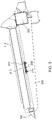
- the belt guide 204 is illustrated in Figure 2 in an exploded view.
- the belt guide 204 is formed in two layers. It includes an elongate support strip 208 that is fixed to the top of the support arms 200 and a wear strip 210 that is fixed to the support strip 208.
- the support strip 208 is fixed to the top of one or more support arms with fasteners 212.
- Fasteners 212 are preferably threaded fasteners, rivets or clips.
- every support arm 200 is fixed to the support strip with a fastener 212.
- a couple of fasteners 212 can be used to fix the opposing ends of the support strip 208 to support arms 200 at opposing ends of the support strip.
- Wear strip 210 is attached to support strip 208 with a plurality of fasteners 214 (such as threaded fasteners, rivets, or clips) better spaced apart and attached adjacent to the leading edge edges and to the trailing edges of the wear strip 210 and the support strip 208.
- fasteners 214 such as threaded fasteners, rivets, or clips
- wear strip 210 can have a C-shaped cross-section in which the elongate forward edge and the elongate rear edge of the wear strip 210 wrap around the sides of the support strip 208, with sufficient friction to hold the wear strip 210 against the support strip 208 with either no fasteners or a reduced number of, fasteners 212, 214.
- the C-shaped profile includes two flanges 500, 502 that extend downward from a central flat portion 504 and engage respecting opposing sides of the support strip 208. This arrangement permits faster replacement of the wear strip 210.
- a plurality of support strips 208 and wear strips 210 according to any of the arrangements and constructions described herein can be disposed in a fore-and-aft, spaced-apart relationship across each of the support arms 200.
- Figure 6 is a cross-sectional view this alternative arrangement showing the location of the multiple strips 208, 210 as they would appear taken at section line 4-4 in Figure 2 .
- Figures 2-6 illustrate the construction and operation of the left side conveyor 108.
- the right side conveyor 110 (including without limitation, its support arms, wear strips, and support strips) is identically constructed and operates identically as the left side conveyor 108, but in mirror image form. For that reason the right side conveyor 110 will not be separately discussed.
Landscapes
- Life Sciences & Earth Sciences (AREA)
- Environmental Sciences (AREA)
- Engineering & Computer Science (AREA)
- Mechanical Engineering (AREA)
- Belt Conveyors (AREA)
- Harvesting Machines For Specific Crops (AREA)
- Harvester Elements (AREA)
- Structure Of Belt Conveyors (AREA)
Claims (12)
- Tête de récolte agricole (100) pour la récolte de cultures dans un champ agricole, la tête de récolte agricole (100) étant conçue pour être fixée sur une moissonneuse-batteuse, la tête de récolte agricole (100) comprenant :une structure allongée (102) qui s'étend perpendiculairement à une direction de déplacement de la tête de récolte (100) lorsqu'elle se déplace dans un champ en récoltant des cultures ;une paroi arrière (104) qui s'étend verticalement et s'étend horizontalement dans une direction parallèle à l'étendue longitudinale de la structure (102) ;un système de convoyeur (106) comprenant un convoyeur gauche (108), un convoyeur droit (110) et un convoyeur central (112), le convoyeur gauche (108) étant un convoyeur à tapis sans fin conçu pour transporter un matériau de cultures coupé latéralement de l'extrémité gauche de la structure (102) à une région centrale de la structure (102), le convoyeur droit (110) étant un convoyeur à tapis sans fin conçu pour transporter un matériau de cultures coupé latéralement de l'extrémité droite de la structure (102) à la région centrale de la structure (102), et le convoyeur central (112) étant disposé de façon à recevoir du matériau de cultures coupé à la fois du convoyeur gauche (108) et du convoyeur droit (110) et pour transporter le matériau de cultures coupé vers l'arrière à travers un trou dans la paroi arrière (104) ;une pluralité de bras de support (200) s'étendant vers l'avant à partir d'une partie arrière de la structure (102) ;un couteau à mouvement alternatif (140) fixé à des extrémités avant de la pluralité de bras de support (200) ;une bande de support (208) fixée au-dessus de la pluralité de bras de support (200) et s'étendant latéralement transversalement à la partie supérieure de la pluralité de bras de support (200) et disposée sous un des tapis sans fin ;le convoyeur gauche (108) et le convoyeur droit (110) s'étendant transversalement à la pluralité de bras de support (200) derrière le couteau à mouvement alternatif (140), et chacun des convoyeurs comprenant un tapis en boucle sans fin (130) supporté sur un rouleau fou (134) et un rouleau d'entraînement (132) ;caractérisée en ce qu'une bande d'usure en plastique (210) est fixée à une surface supérieure de la bande de support (208) pour supporter un brin de retour du tapis en boucle sans fin (130).
- Tête de récolte agricole (100) selon la revendication 1, dans laquelle la bande d'usure en plastique (210) mesure entre 10 et 30 cm de large.
- Tête de récolte agricole (100) selon la revendication 1, dans laquelle la bande d'usure en plastique (210) comprend un matériau thermoplastique à haut poids moléculaire.
- Tête de récolte agricole (100) selon la revendication 3, dans laquelle la bande d'usure en plastique (210) comprend du polyéthylène ou du nylon.
- Tête de récolte agricole (100) selon la revendication 1, dans laquelle la bande d'usure en plastique (210) présente une section transversale en forme de C.
- Tête de récolte agricole (100) selon la revendication 5, dans laquelle la bande d'usure en plastique (210) comprend une partie centrale s'étendant transversalement à la largeur de la bande de support (208), une première ailette (500) s'étendant vers le bas sur un côté de la partie centrale, et une seconde ailette (502) s'étendant vers le bas sur le côté opposé de la partie centrale.
- Tête de récolte agricole (100) selon la revendication 6, dans laquelle la première ailette (500) et la seconde ailette (502) viennent en prise avec des côtés opposés de la bande de support (208) et maintiennent ainsi conjointement la bande d'usure en plastique (210) sur la bande de support (208).
- Tête de récolte agricole (100) selon la revendication 1, dans laquelle la bande de support (208) est attachée à la pluralité de bras de support (200) au moyen d'une première pluralité d'éléments de fixation (212), et dans laquelle la bande d'usure en plastique (210) est attachée à la bande de support (208) au moyen d'une seconde pluralité d'éléments de fixation (214).
- Tête de récolte agricole (100) selon la revendication 8, dans laquelle la première pluralité d'éléments de fixation (212) comprend des éléments de fixation filetés, des rivets ou des agrafes.
- Tête de récolte agricole (100) selon la revendication 9, dans laquelle la seconde pluralité d'éléments de fixation (214) comprend des éléments de fixation filetés, des rivets ou des agrafes.
- Tête de récolte agricole (100) selon la revendication 1, dans laquelle la bande de support (208) et la bande d'usure en plastique (210) présentent la même largeur.
- Tête de récolte agricole selon la revendication 11, dans laquelle la même largeur est comprise entre 10 et 30 cm.
Applications Claiming Priority (1)
| Application Number | Priority Date | Filing Date | Title |
|---|---|---|---|
| US15/730,267 US10390486B2 (en) | 2017-10-11 | 2017-10-11 | Polymer used as draper belt contact surface |
Publications (2)
| Publication Number | Publication Date |
|---|---|
| EP3469874A1 EP3469874A1 (fr) | 2019-04-17 |
| EP3469874B1 true EP3469874B1 (fr) | 2022-05-04 |
Family
ID=63798881
Family Applications (1)
| Application Number | Title | Priority Date | Filing Date |
|---|---|---|---|
| EP18199262.9A Active EP3469874B1 (fr) | 2017-10-11 | 2018-10-09 | Tête de récolte agricole avec convoyeur à courroie |
Country Status (3)
| Country | Link |
|---|---|
| US (1) | US10390486B2 (fr) |
| EP (1) | EP3469874B1 (fr) |
| BR (1) | BR102018070818B1 (fr) |
Families Citing this family (8)
| Publication number | Priority date | Publication date | Assignee | Title |
|---|---|---|---|---|
| US10568265B2 (en) * | 2017-10-31 | 2020-02-25 | Deere & Company | Draper belt roller support |
| DE102019125279A1 (de) * | 2019-09-19 | 2021-03-25 | Carl Geringhoff Gmbh & Co. Kg | Schneidwerk mit längsbeweglichem Abstützelement zur Abstützung einer Förderfläche |
| DE102019125277A1 (de) * | 2019-09-19 | 2021-03-25 | Carl Geringhoff Gmbh & Co. Kg | Schneidwerk mit Blattfederpaket als Schneidelementträger |
| US11297770B2 (en) * | 2019-11-13 | 2022-04-12 | Cnh Industrial America Llc | Draper belt assembly for an agricultural harvester |
| GB202020459D0 (en) * | 2020-12-23 | 2021-02-03 | Agco Int Gmbh | Forage harvester |
| USD1009948S1 (en) | 2022-06-17 | 2024-01-02 | Macdon Industries Ltd. | Draper track |
| USD1012134S1 (en) | 2022-06-17 | 2024-01-23 | Macdon Industries Ltd | Draper track |
| USD1014571S1 (en) | 2022-06-17 | 2024-02-13 | Macdon Industries Ltd. | Draper track |
Family Cites Families (31)
| Publication number | Priority date | Publication date | Assignee | Title |
|---|---|---|---|---|
| US2685958A (en) * | 1954-08-10 | Wiper for wear strips of endless | ||
| US1862101A (en) * | 1931-05-02 | 1932-06-07 | Jacob G Pax | Harvester |
| US2347365A (en) * | 1941-10-18 | 1944-04-25 | Deere & Co | Harvesting mechanism |
| US3344909A (en) * | 1965-09-08 | 1967-10-03 | Sargents Sons Corp C G | Conveyor seals |
| US5478277A (en) | 1994-05-02 | 1995-12-26 | Kloefkorn; Melvin L. | Force feeder chain assembly |
| US5459986A (en) * | 1994-12-27 | 1995-10-24 | Macdon Industries Ltd. | Draper header with canvas to cutter bar seal |
| US20020129591A1 (en) * | 2001-03-19 | 2002-09-19 | Patterson Roger L. | Crop stripper for the crop transport draper of a header |
| US7073661B2 (en) * | 2004-03-04 | 2006-07-11 | Tennant | Self cleaning conveyor with roller scraper and debris reduction skirt |
| US20080271426A1 (en) * | 2006-02-10 | 2008-11-06 | Agco Corporation | Draper belt with crop-retaining rib |
| US20070193243A1 (en) * | 2006-02-10 | 2007-08-23 | Schmidt James R | Combine Harvester Draper Header Having Flexible Cutterbar |
| CA2564777C (fr) * | 2006-10-20 | 2010-08-03 | Macdon Industries Ltd. | Tete de moissonneuse-batteuse comportant un convoyeur a toile et un joint d'etancheite avec un element de la barre de coupe |
| US20080276591A1 (en) | 2007-05-07 | 2008-11-13 | Claas Omaha, Inc. | Draper belt rib apparatus and method |
| US7640720B1 (en) * | 2008-06-11 | 2010-01-05 | Deere & Company | Draper belt construction to control translation |
| US7971418B2 (en) * | 2009-07-09 | 2011-07-05 | Deere & Company | Header with extendible cutter bar |
| US8205421B2 (en) * | 2010-06-16 | 2012-06-26 | Agco Corporation | Belt guard crop dam for flexible draper header |
| US7958711B1 (en) * | 2010-06-16 | 2011-06-14 | Agco Corporation | Crop deflector for ends of draper belt of flexible draper header |
| US8281561B2 (en) * | 2010-08-17 | 2012-10-09 | Deere & Company | Flexible draper belt drive for an agricultural harvesting machine |
| US8065865B1 (en) * | 2010-08-17 | 2011-11-29 | Deere & Company | Spring assisted translating draper belt drive rollers for an agricultural harvesting machine |
| US8322520B2 (en) * | 2010-08-17 | 2012-12-04 | Deere & Company | Tongue-in-groove belt hold down for a draper platform |
| DE102010037131A1 (de) | 2010-08-24 | 2012-03-01 | Claas Selbstfahrende Erntemaschinen Gmbh | Schneidwerk |
| CA2734475C (fr) * | 2011-03-16 | 2012-10-09 | Macdon Industries Ltd. | Rouleau d'entrainement de convoyeur a toile d'une tete de moissonneuse-batteuse |
| US8291686B1 (en) * | 2011-06-17 | 2012-10-23 | Macdon Industries Ltd | Draper canvas with a shaped edge |
| US8695315B2 (en) * | 2012-08-09 | 2014-04-15 | Deere & Company | Draper header with pivoting side draper conveyors |
| US8484939B1 (en) * | 2012-08-31 | 2013-07-16 | Macdon Industries Ltd. | Draper seal for crop harvesting header |
| US8511050B1 (en) * | 2012-08-31 | 2013-08-20 | Macdon Industries Ltd. | Draper support of a crop harvesting header |
| US8752359B2 (en) * | 2012-08-31 | 2014-06-17 | Macdon Industries Ltd. | Draper support of a crop harvesting header |
| DE102013100322A1 (de) * | 2013-01-14 | 2014-07-17 | Claas Selbstfahrende Erntemaschinen Gmbh | Schneidwerk |
| WO2015084604A2 (fr) * | 2013-12-05 | 2015-06-11 | The Procter & Gamble Company | Appareil et procédé de transport d'articles absorbants |
| US20150195992A1 (en) * | 2014-01-13 | 2015-07-16 | Deere & Company | Draper Roller with Active Retracting Cleat Crop Stripper |
| BE1023963A9 (nl) * | 2016-03-14 | 2017-10-11 | Cnh Ind Belgium Nv | Toevoergeheel met een afgeschermd kettingwiel voor gebruik in de landbouw |
| US10647516B2 (en) * | 2017-03-31 | 2020-05-12 | Deere & Company | Cogged feederhouse front drum |
-
2017
- 2017-10-11 US US15/730,267 patent/US10390486B2/en active Active
-
2018
- 2018-10-09 BR BR102018070818-0A patent/BR102018070818B1/pt active IP Right Grant
- 2018-10-09 EP EP18199262.9A patent/EP3469874B1/fr active Active
Also Published As
| Publication number | Publication date |
|---|---|
| EP3469874A1 (fr) | 2019-04-17 |
| US20190104684A1 (en) | 2019-04-11 |
| BR102018070818A2 (pt) | 2019-05-07 |
| BR102018070818B1 (pt) | 2023-10-24 |
| US10390486B2 (en) | 2019-08-27 |
Similar Documents
| Publication | Publication Date | Title |
|---|---|---|
| EP3469874B1 (fr) | Tête de récolte agricole avec convoyeur à courroie | |
| USRE50592E1 (en) | Draper seal for crop header | |
| US8752359B2 (en) | Draper support of a crop harvesting header | |
| CA2812516C (fr) | Support de convoyeur a toile d'un tablier de coupe pour recolteuse | |
| US7908836B1 (en) | Draper header with multiple sided cut crop barrier interface between the cutter bar and draper canvas | |
| US8769919B2 (en) | Crop harvesting header with sealing member between draper and cutter bar | |
| US8322520B2 (en) | Tongue-in-groove belt hold down for a draper platform | |
| EP2145525A2 (fr) | Guide de courroie sectionné pour courroie de transport dans une moissonneuse agricole | |
| US9750190B2 (en) | Harvesting head upper belt conveyor compressing crop against a center belt conveyor | |
| US10314234B2 (en) | Guide assembly for a lateral draper of a header for an agricultural harvester | |
| US20120291412A1 (en) | Pivoting center conveyor for draper platform | |
| US10918017B2 (en) | Draper canvas seal | |
| EP3516941B1 (fr) | Connexion des extrémités du convoyeur de tuloteuse d'une tête de récolte | |
| EP2700295A1 (fr) | Tête de récolte avec déflecteur | |
| EP2890238A1 (fr) | Joint d'étanchéité de tuloteuse pour tête de moissonneuse | |
| US10624266B2 (en) | Connecting ends of the draper conveyor of a harvest header | |
| US20250374858A1 (en) | Plastic draper track |
Legal Events
| Date | Code | Title | Description |
|---|---|---|---|
| PUAI | Public reference made under article 153(3) epc to a published international application that has entered the european phase |
Free format text: ORIGINAL CODE: 0009012 |
|
| STAA | Information on the status of an ep patent application or granted ep patent |
Free format text: STATUS: THE APPLICATION HAS BEEN PUBLISHED |
|
| AK | Designated contracting states |
Kind code of ref document: A1 Designated state(s): AL AT BE BG CH CY CZ DE DK EE ES FI FR GB GR HR HU IE IS IT LI LT LU LV MC MK MT NL NO PL PT RO RS SE SI SK SM TR |
|
| AX | Request for extension of the european patent |
Extension state: BA ME |
|
| STAA | Information on the status of an ep patent application or granted ep patent |
Free format text: STATUS: REQUEST FOR EXAMINATION WAS MADE |
|
| 17P | Request for examination filed |
Effective date: 20191017 |
|
| RBV | Designated contracting states (corrected) |
Designated state(s): AL AT BE BG CH CY CZ DE DK EE ES FI FR GB GR HR HU IE IS IT LI LT LU LV MC MK MT NL NO PL PT RO RS SE SI SK SM TR |
|
| GRAP | Despatch of communication of intention to grant a patent |
Free format text: ORIGINAL CODE: EPIDOSNIGR1 |
|
| STAA | Information on the status of an ep patent application or granted ep patent |
Free format text: STATUS: GRANT OF PATENT IS INTENDED |
|
| INTG | Intention to grant announced |
Effective date: 20211221 |
|
| GRAS | Grant fee paid |
Free format text: ORIGINAL CODE: EPIDOSNIGR3 |
|
| GRAA | (expected) grant |
Free format text: ORIGINAL CODE: 0009210 |
|
| STAA | Information on the status of an ep patent application or granted ep patent |
Free format text: STATUS: THE PATENT HAS BEEN GRANTED |
|
| AK | Designated contracting states |
Kind code of ref document: B1 Designated state(s): AL AT BE BG CH CY CZ DE DK EE ES FI FR GB GR HR HU IE IS IT LI LT LU LV MC MK MT NL NO PL PT RO RS SE SI SK SM TR |
|
| REG | Reference to a national code |
Ref country code: GB Ref legal event code: FG4D |
|
| REG | Reference to a national code |
Ref country code: CH Ref legal event code: EP |
|
| REG | Reference to a national code |
Ref country code: AT Ref legal event code: REF Ref document number: 1488031 Country of ref document: AT Kind code of ref document: T Effective date: 20220515 |
|
| REG | Reference to a national code |
Ref country code: DE Ref legal event code: R096 Ref document number: 602018034832 Country of ref document: DE |
|
| REG | Reference to a national code |
Ref country code: IE Ref legal event code: FG4D |
|
| REG | Reference to a national code |
Ref country code: LT Ref legal event code: MG9D |
|
| REG | Reference to a national code |
Ref country code: NL Ref legal event code: MP Effective date: 20220504 |
|
| REG | Reference to a national code |
Ref country code: AT Ref legal event code: MK05 Ref document number: 1488031 Country of ref document: AT Kind code of ref document: T Effective date: 20220504 |
|
| PG25 | Lapsed in a contracting state [announced via postgrant information from national office to epo] |
Ref country code: SE Free format text: LAPSE BECAUSE OF FAILURE TO SUBMIT A TRANSLATION OF THE DESCRIPTION OR TO PAY THE FEE WITHIN THE PRESCRIBED TIME-LIMIT Effective date: 20220504 Ref country code: PT Free format text: LAPSE BECAUSE OF FAILURE TO SUBMIT A TRANSLATION OF THE DESCRIPTION OR TO PAY THE FEE WITHIN THE PRESCRIBED TIME-LIMIT Effective date: 20220905 Ref country code: NO Free format text: LAPSE BECAUSE OF FAILURE TO SUBMIT A TRANSLATION OF THE DESCRIPTION OR TO PAY THE FEE WITHIN THE PRESCRIBED TIME-LIMIT Effective date: 20220804 Ref country code: NL Free format text: LAPSE BECAUSE OF FAILURE TO SUBMIT A TRANSLATION OF THE DESCRIPTION OR TO PAY THE FEE WITHIN THE PRESCRIBED TIME-LIMIT Effective date: 20220504 Ref country code: LT Free format text: LAPSE BECAUSE OF FAILURE TO SUBMIT A TRANSLATION OF THE DESCRIPTION OR TO PAY THE FEE WITHIN THE PRESCRIBED TIME-LIMIT Effective date: 20220504 Ref country code: HR Free format text: LAPSE BECAUSE OF FAILURE TO SUBMIT A TRANSLATION OF THE DESCRIPTION OR TO PAY THE FEE WITHIN THE PRESCRIBED TIME-LIMIT Effective date: 20220504 Ref country code: GR Free format text: LAPSE BECAUSE OF FAILURE TO SUBMIT A TRANSLATION OF THE DESCRIPTION OR TO PAY THE FEE WITHIN THE PRESCRIBED TIME-LIMIT Effective date: 20220805 Ref country code: FI Free format text: LAPSE BECAUSE OF FAILURE TO SUBMIT A TRANSLATION OF THE DESCRIPTION OR TO PAY THE FEE WITHIN THE PRESCRIBED TIME-LIMIT Effective date: 20220504 Ref country code: ES Free format text: LAPSE BECAUSE OF FAILURE TO SUBMIT A TRANSLATION OF THE DESCRIPTION OR TO PAY THE FEE WITHIN THE PRESCRIBED TIME-LIMIT Effective date: 20220504 Ref country code: BG Free format text: LAPSE BECAUSE OF FAILURE TO SUBMIT A TRANSLATION OF THE DESCRIPTION OR TO PAY THE FEE WITHIN THE PRESCRIBED TIME-LIMIT Effective date: 20220804 Ref country code: AT Free format text: LAPSE BECAUSE OF FAILURE TO SUBMIT A TRANSLATION OF THE DESCRIPTION OR TO PAY THE FEE WITHIN THE PRESCRIBED TIME-LIMIT Effective date: 20220504 |
|
| PG25 | Lapsed in a contracting state [announced via postgrant information from national office to epo] |
Ref country code: RS Free format text: LAPSE BECAUSE OF FAILURE TO SUBMIT A TRANSLATION OF THE DESCRIPTION OR TO PAY THE FEE WITHIN THE PRESCRIBED TIME-LIMIT Effective date: 20220504 Ref country code: PL Free format text: LAPSE BECAUSE OF FAILURE TO SUBMIT A TRANSLATION OF THE DESCRIPTION OR TO PAY THE FEE WITHIN THE PRESCRIBED TIME-LIMIT Effective date: 20220504 Ref country code: LV Free format text: LAPSE BECAUSE OF FAILURE TO SUBMIT A TRANSLATION OF THE DESCRIPTION OR TO PAY THE FEE WITHIN THE PRESCRIBED TIME-LIMIT Effective date: 20220504 Ref country code: IS Free format text: LAPSE BECAUSE OF FAILURE TO SUBMIT A TRANSLATION OF THE DESCRIPTION OR TO PAY THE FEE WITHIN THE PRESCRIBED TIME-LIMIT Effective date: 20220904 |
|
| PG25 | Lapsed in a contracting state [announced via postgrant information from national office to epo] |
Ref country code: SM Free format text: LAPSE BECAUSE OF FAILURE TO SUBMIT A TRANSLATION OF THE DESCRIPTION OR TO PAY THE FEE WITHIN THE PRESCRIBED TIME-LIMIT Effective date: 20220504 Ref country code: SK Free format text: LAPSE BECAUSE OF FAILURE TO SUBMIT A TRANSLATION OF THE DESCRIPTION OR TO PAY THE FEE WITHIN THE PRESCRIBED TIME-LIMIT Effective date: 20220504 Ref country code: RO Free format text: LAPSE BECAUSE OF FAILURE TO SUBMIT A TRANSLATION OF THE DESCRIPTION OR TO PAY THE FEE WITHIN THE PRESCRIBED TIME-LIMIT Effective date: 20220504 Ref country code: EE Free format text: LAPSE BECAUSE OF FAILURE TO SUBMIT A TRANSLATION OF THE DESCRIPTION OR TO PAY THE FEE WITHIN THE PRESCRIBED TIME-LIMIT Effective date: 20220504 Ref country code: DK Free format text: LAPSE BECAUSE OF FAILURE TO SUBMIT A TRANSLATION OF THE DESCRIPTION OR TO PAY THE FEE WITHIN THE PRESCRIBED TIME-LIMIT Effective date: 20220504 Ref country code: CZ Free format text: LAPSE BECAUSE OF FAILURE TO SUBMIT A TRANSLATION OF THE DESCRIPTION OR TO PAY THE FEE WITHIN THE PRESCRIBED TIME-LIMIT Effective date: 20220504 |
|
| REG | Reference to a national code |
Ref country code: DE Ref legal event code: R097 Ref document number: 602018034832 Country of ref document: DE |
|
| PLBE | No opposition filed within time limit |
Free format text: ORIGINAL CODE: 0009261 |
|
| STAA | Information on the status of an ep patent application or granted ep patent |
Free format text: STATUS: NO OPPOSITION FILED WITHIN TIME LIMIT |
|
| PG25 | Lapsed in a contracting state [announced via postgrant information from national office to epo] |
Ref country code: AL Free format text: LAPSE BECAUSE OF FAILURE TO SUBMIT A TRANSLATION OF THE DESCRIPTION OR TO PAY THE FEE WITHIN THE PRESCRIBED TIME-LIMIT Effective date: 20220504 |
|
| 26N | No opposition filed |
Effective date: 20230207 |
|
| PG25 | Lapsed in a contracting state [announced via postgrant information from national office to epo] |
Ref country code: SI Free format text: LAPSE BECAUSE OF FAILURE TO SUBMIT A TRANSLATION OF THE DESCRIPTION OR TO PAY THE FEE WITHIN THE PRESCRIBED TIME-LIMIT Effective date: 20220504 Ref country code: MC Free format text: LAPSE BECAUSE OF FAILURE TO SUBMIT A TRANSLATION OF THE DESCRIPTION OR TO PAY THE FEE WITHIN THE PRESCRIBED TIME-LIMIT Effective date: 20220504 |
|
| REG | Reference to a national code |
Ref country code: CH Ref legal event code: PL |
|
| REG | Reference to a national code |
Ref country code: BE Ref legal event code: MM Effective date: 20221031 |
|
| GBPC | Gb: european patent ceased through non-payment of renewal fee |
Effective date: 20221009 |
|
| PG25 | Lapsed in a contracting state [announced via postgrant information from national office to epo] |
Ref country code: LU Free format text: LAPSE BECAUSE OF NON-PAYMENT OF DUE FEES Effective date: 20221009 |
|
| PG25 | Lapsed in a contracting state [announced via postgrant information from national office to epo] |
Ref country code: LI Free format text: LAPSE BECAUSE OF NON-PAYMENT OF DUE FEES Effective date: 20221031 Ref country code: FR Free format text: LAPSE BECAUSE OF NON-PAYMENT OF DUE FEES Effective date: 20221031 Ref country code: CH Free format text: LAPSE BECAUSE OF NON-PAYMENT OF DUE FEES Effective date: 20221031 |
|
| PG25 | Lapsed in a contracting state [announced via postgrant information from national office to epo] |
Ref country code: BE Free format text: LAPSE BECAUSE OF NON-PAYMENT OF DUE FEES Effective date: 20221031 |
|
| PG25 | Lapsed in a contracting state [announced via postgrant information from national office to epo] |
Ref country code: IE Free format text: LAPSE BECAUSE OF NON-PAYMENT OF DUE FEES Effective date: 20221009 Ref country code: GB Free format text: LAPSE BECAUSE OF NON-PAYMENT OF DUE FEES Effective date: 20221009 |
|
| PG25 | Lapsed in a contracting state [announced via postgrant information from national office to epo] |
Ref country code: IT Free format text: LAPSE BECAUSE OF FAILURE TO SUBMIT A TRANSLATION OF THE DESCRIPTION OR TO PAY THE FEE WITHIN THE PRESCRIBED TIME-LIMIT Effective date: 20220504 |
|
| PG25 | Lapsed in a contracting state [announced via postgrant information from national office to epo] |
Ref country code: HU Free format text: LAPSE BECAUSE OF FAILURE TO SUBMIT A TRANSLATION OF THE DESCRIPTION OR TO PAY THE FEE WITHIN THE PRESCRIBED TIME-LIMIT; INVALID AB INITIO Effective date: 20181009 |
|
| PG25 | Lapsed in a contracting state [announced via postgrant information from national office to epo] |
Ref country code: CY Free format text: LAPSE BECAUSE OF FAILURE TO SUBMIT A TRANSLATION OF THE DESCRIPTION OR TO PAY THE FEE WITHIN THE PRESCRIBED TIME-LIMIT Effective date: 20220504 |
|
| PG25 | Lapsed in a contracting state [announced via postgrant information from national office to epo] |
Ref country code: MK Free format text: LAPSE BECAUSE OF FAILURE TO SUBMIT A TRANSLATION OF THE DESCRIPTION OR TO PAY THE FEE WITHIN THE PRESCRIBED TIME-LIMIT Effective date: 20220504 |
|
| PG25 | Lapsed in a contracting state [announced via postgrant information from national office to epo] |
Ref country code: MT Free format text: LAPSE BECAUSE OF FAILURE TO SUBMIT A TRANSLATION OF THE DESCRIPTION OR TO PAY THE FEE WITHIN THE PRESCRIBED TIME-LIMIT Effective date: 20220504 |
|
| PG25 | Lapsed in a contracting state [announced via postgrant information from national office to epo] |
Ref country code: BG Free format text: LAPSE BECAUSE OF FAILURE TO SUBMIT A TRANSLATION OF THE DESCRIPTION OR TO PAY THE FEE WITHIN THE PRESCRIBED TIME-LIMIT Effective date: 20220504 |
|
| PG25 | Lapsed in a contracting state [announced via postgrant information from national office to epo] |
Ref country code: BG Free format text: LAPSE BECAUSE OF FAILURE TO SUBMIT A TRANSLATION OF THE DESCRIPTION OR TO PAY THE FEE WITHIN THE PRESCRIBED TIME-LIMIT Effective date: 20220504 |
|
| PG25 | Lapsed in a contracting state [announced via postgrant information from national office to epo] |
Ref country code: TR Free format text: LAPSE BECAUSE OF FAILURE TO SUBMIT A TRANSLATION OF THE DESCRIPTION OR TO PAY THE FEE WITHIN THE PRESCRIBED TIME-LIMIT Effective date: 20220504 |
|
| PGFP | Annual fee paid to national office [announced via postgrant information from national office to epo] |
Ref country code: DE Payment date: 20250919 Year of fee payment: 8 |