EP3469899B1 - Machine d'épandage agricole et procédé de commande d'une telle machine d'épandage - Google Patents
Machine d'épandage agricole et procédé de commande d'une telle machine d'épandage Download PDFInfo
- Publication number
- EP3469899B1 EP3469899B1 EP18195135.1A EP18195135A EP3469899B1 EP 3469899 B1 EP3469899 B1 EP 3469899B1 EP 18195135 A EP18195135 A EP 18195135A EP 3469899 B1 EP3469899 B1 EP 3469899B1
- Authority
- EP
- European Patent Office
- Prior art keywords
- distribution machine
- distribution
- lane
- boundary structure
- agricultural
- Prior art date
- Legal status (The legal status is an assumption and is not a legal conclusion. Google has not performed a legal analysis and makes no representation as to the accuracy of the status listed.)
- Active
Links
Images



Classifications
-
- A—HUMAN NECESSITIES
- A01—AGRICULTURE; FORESTRY; ANIMAL HUSBANDRY; HUNTING; TRAPPING; FISHING
- A01M—CATCHING, TRAPPING OR SCARING OF ANIMALS; APPARATUS FOR THE DESTRUCTION OF NOXIOUS ANIMALS OR NOXIOUS PLANTS
- A01M7/00—Special adaptations or arrangements of liquid-spraying apparatus for purposes covered by this subclass
- A01M7/005—Special arrangements or adaptations of the spraying or distributing parts, e.g. adaptations or mounting of the spray booms, mounting of the nozzles, protection shields
- A01M7/0053—Mounting of the spraybooms
- A01M7/0057—Mounting of the spraybooms with active regulation of the boom position
Definitions
- the present invention relates to an agricultural spreading machine for spreading liquids and/or grainy or granulated substances with the features of the preamble of independent claim 1.
- the invention also relates to a method for controlling and/or regulating a spreading machine with the features of the preamble of independent method claim 15
- a wide variety of embodiments of distribution machines are used in agriculture for dispensing a wide variety of active ingredients such as liquids and/or granular or granulated substances. Such agricultural distribution machines are often also referred to as field sprayers.
- the distribution machines In order to distribute the respective active substances, the distribution machines generally have a distribution device which, in the working position, extends transversely to the direction of travel.
- the distribution machines can be designed both as self-propelled distributors or as distributors that are attached or attached to a towing vehicle.
- the distribution devices or the distribution devices also known as spray booms, sometimes have large working widths of twenty meters and more, with such distribution devices usually being divided into several boom segments, which are each arranged pivotable to each other about upright axes and thus, among other things, for a transport trip, around them upright axles can be folded into a maximum permissible transport width for the transport journey.
- Such a distribution machine is, for example, from the EP 2 829 177 B1 already out.
- the agricultural distribution machine is used to spread liquid and/or solid active ingredients and includes, among other things, a distribution device arranged transversely to the direction of travel with a central part and lateral sections rotatably mounted on this via vertical or upright pivoting and rotating axes, the pivoting and rotating axes with damping elements are provided and means for reducing a spring travel of the lateral sections are arranged between the central part and the lateral sections.
- the damping elements can be controlled or regulated via a control unit depending on the current type of movement of the distribution machine.
- Comparable systems go from the EP 2 835 050 A1 as well as the EP 2 837 285 A1 out.
- means are provided for detecting these vibrations.
- the means can in particular be a camera system.
- the optimum steps for correcting and optimizing the movements of the distribution device are derived on the basis of the lifting, yawing and rolling movements recorded by the camera, with the rolling movements being controlled for this purpose, in particular by means of a damper system operated with electrical energy.
- This system also does not provide for any controlled adjustment of the distribution device, for example in order to be able to process corners or curves of an arable land, and it does not take into account the boundaries and edge structures of the arable land.
- a method for correcting position coordinates stored in a memory of a working computer of an agricultural distribution machine, for example recorded by means of a GPS system is based on EP 2 983 010 A1 out.
- the method described here should be characterized by two shifting operations, preferably perpendicular to one another, of the stored position coordinates relative to the current position, with the first of these shifting operations being carried out on the basis of position and/or direction of movement data of the work machine, preferably determined on the basis of the direction of travel.
- the current position determination of the machine can be improved, the method also does not provide for a controlled adjustment of the distribution device, for example in order to be able to work on corners or peaks or curves or the like of an arable land.
- the route planning system includes position determination devices in order to determine a current position of the distribution machines in question, route planning data determination devices in order to to make the necessary route planning data available, e.g. by automatically recording the position data and other additional information and/or by input by an operator and communication devices in order to send the route planning data.
- position determination devices in order to determine a current position of the distribution machines in question
- route planning data determination devices in order to make the necessary route planning data available, e.g. by automatically recording the position data and other additional information and/or by input by an operator and communication devices in order to send the route planning data.
- a distributor with an improved system for section control goes out of the EP 2 918 157 B1 out.
- the system includes an angle sensor that can measure the angle between a towing vehicle and the distribution device.
- the distribution machine includes a position sensor that can measure the position of a towing vehicle of the distribution machine or the position of the distribution machine and thus the sections of the distribution device are switched depending on the position and the angle respectively.
- the system does not provide for an active change in the position or the angle of the spreading device in relation to the spreading machine, for example in order to be able to process certain fields.
- the EP 1 716 754 B1 an agricultural spreading machine with a frame and a storage container arranged on the frame and with a spreading device arranged on the frame by means of a suspension device, which is suspended pivotably about an upright axis relative to the frame, wherein between the frame and the spreading device at least one of preferably an electronic Control device controllable motorized actuator is provided for adjusting the distributor linkage about the upright axis, and that means are available by which the distribution device is always aligned at right angles to the desired direction or to the lane of the distribution machine by means of the actuator, ie that, especially when cornering, the distribution device is always aligned at right angles to the frame or to the direction of travel of the distribution machine, which means that it is not possible to treat corners or peaks or curves that deviate from the lane or the like of an arable area.
- the entire distribution device is pivoted accordingly, which in turn can lead to incorrect treatments.
- the distribution device is also pivoted solely on the basis of the detected position or the respective desired direction, as a result of which the distribution device is sometimes pivoted quickly.
- this can in turn lead to incorrect treatments, since the pivoting of the entire distribution device sometimes causes some sub-areas to be treated twice and some sub-areas to be treated with too few active ingredients, which is further aggravated by the uncontrolled speed.
- a wide variety of systems are thus known from the prior art, in order in particular to influence the damping properties of a distribution device and to pivot a distribution device about an upright axis. It is also known to define a wide variety of lanes along which the distribution machines are guided.
- the invention is therefore based on the object of creating an agricultural spreading machine with a spreading device with a large working width and a method for controlling such spreading machines, with which it is simplified, even corners with obtuse or acute or right angles and curvy borders or edge structures of an arable land to process or treat without damaging the plant population and at the same time largely avoiding double treatments.
- the invention proposes an agricultural spreading machine to solve the above-mentioned tasks.
- the agricultural spreader can be designed as a self-propelled spreader or as a spreader towed by a towing vehicle or as a spreader attached to a towing vehicle.
- the connection between the spreader and the towing vehicle can be established by means of a towing device or drawbar that is known per se.
- the distribution machine can also be designed as an autonomous vehicle or be an autonomous distribution machine with a distribution device.
- the distribution machine comprises at least one frame for carrying the respective components, one or more storage containers for carrying and preparing the respective distribution material, and a distribution device that extends transversely to the direction of travel in a working position, on which distribution device in particular downward-pointing dispensing nozzles for dispensing and distributing the respective liquids and/or the granular or granulated substances are attached.
- the distribution device is movably arranged on the frame, whereby the distribution device for this purpose can be attached to the frame, for example by means of a parallelogram or by means of a linear carriage, the height of which can also be adjusted, but it can also be attached directly to the frame.
- the attachment of the distribution device is only referred to the frame in the following, although this does not exclude a connection, e.g. by means of a parallelogram or similar intermediate frame between the distribution device and the frame, but the term frame also applies to such Embodiments relates.
- the distribution device can be divided into several linkage segments, e.g. into a middle part and two side parts, preferably located on the left and right of the middle part and attached to it via upright axes so that they can pivot, whereby the side parts can also be made up of several side parts that can also be pivoted to one another by means of upright axes
- Linkage segments can be assembled.
- a linkage of a distribution machine can be composed of a total of eleven linkage segments, which can each be pivoted relative to one another about upright axes. Any other number of linkage segments would also be conceivable.
- the distribution device or its central part can also be attached to the frame or to a parallelogram or linear slide or similar frame assigned to the frame so that it can be pivoted about an upright axis, i.e. the entire distribution device could be pivoted accordingly.
- the pivoting of the respective linkage segments or the distribution device about the upright axes takes place by means of at least one motorized actuator that can be controlled by an electronic control device.
- sensors are assigned to the distribution device and/or the linkage segments and/or the upright axles and/or the at least one motorized actuator in such a way that they record an actual value with regard to the existing orientation or the current relative position and forward it to a control device or output it be able. By means of the sensors it is thus detected, for example, which angle the respective linkage segments have in relation to one another or which angle the distribution device or its central part has in relation to the frame.
- the distribution machine can have at least one running gear formed from at least two wheels or one or more steerable axles have, wherein the wheels can in turn be pivotable or steerable to the frame via upright axles, and wherein at least one motorized actuator controllable by an electronic control device can be provided for the steering.
- sensors can also be assigned to the chassis and/or the upright axles and/or the at least one motorized actuator for steering in such a way that they record an actual value with regard to the existing alignment or the current relative position and forward it to a control device or output it be able.
- the agricultural spreading machine can have four wheels, with two opposite wheels forming a chassis or an axle and with at least the wheels of the front axle or only the wheels of the rear axle or the wheels of both axles being pivotable or rotatable about upright axles, for example. are arranged steerable to the frame.
- the axles can also be mounted on a frame that supports the components of the distribution machine.
- the distribution machine can include a motor that drives the distribution machine and a cab.
- the agricultural spreader as a spreader towed by a towing vehicle, it could have a towing device or a drawbar or the like for connection to the towing vehicle, in which case the towing device can also be attached to the frame so that it can be pivoted or steered about an upright axis and likewise, in turn, a position or orientation of the traction device in relation to the frame can be changed by means of a motorized actuator, in order thus also to steer the distribution machine.
- sensors can also be assigned to the towing device and/or the upright axles and/or the at least one motorized actuator for steering in such a way that they record an actual value with regard to the existing orientation or the current relative position and forward it to a control device or output it be able.
- the distribution device can be pivoted about an axis of rotation running in the direction of travel by means of at least one drive element in accordance with a ground contour, in order to achieve the most exact possible adjustment to the respective ground contour or the respective horizon or to keep the distances between the distribution device and the ground contour or the ground contour as equal as possible .to reach a stand of plants.
- the sensors are used to record, for example, what angle the respective wheels and/or the towing device have to the frame or to the distribution machine, in order to obtain an evaluation of the current steering angle, for example.
- Both a steerable axle and a steerable traction device can also be provided, in which case both the traction device and the running gear or its wheels can each be pivoted or steered by means of a separate or by means of a common actuator.
- contour determination devices assigned to and/or connected to a control device of the distributor to be provided for detecting and/or evaluating an existing edge structure of the distributor and for detecting and/or evaluating a lane of the distributor and/or assigned and/or or lane determination devices connected to a control device of the distribution machine are provided, and wherein the motorized actuators are activated as a function of an existing edge structure and an existing track track takes place in such a way that the distribution device and/or its linkage segments have an orientation that is at least largely parallel and/or perpendicular to the edge structure.
- the distribution device or its linkage segments are each moved by means of and/or the actuator(s) in such a way that they are at least largely parallel and/or perpendicular to the detected or existing edge structure have, whereby existing corners or curves or edge structures with a wide variety of angles can be treated accordingly over the entire surface and double treatments can also be largely avoided, as well as that the steering following the lane avoids running over plants.
- the lanes can be traveled on accordingly both when driving forwards and when driving backwards.
- the sensors for detecting the respective orientation or the respective relative position can in particular be angle potentiometers or angle sensors or position sensors or similar sensors. Linear measuring systems would also be conceivable or usable. In general, any sensors would therefore be conceivable, by means of which an alignment can be detected or determined.
- the signals detected by the sensors can be transmitted accordingly to the control device, with the signals then being converted into corresponding values of the relative positions by means of a control program stored in the control device.
- the distribution machine can be guided along a definable or a defined lane; This means that, for example, the wheels or the drawbar or the spreading machine is steered in such a way that it follows a lane, which in turn can prevent or reduce the risk of plants being run over.
- lane determination devices can be assigned to the distribution machine and/or connected to a control device. So-called tramlines, for example, could be used as lanes, which can be recorded by means of additional measuring means or whose data can be stored in the control device.
- a laser scanner and/or a camera or a camera system and/or a radar sensor could also be provided as lane detection devices.
- a GPS system could also be provided on the distribution machine for lane determination.
- the respective lanes could be read from a database, for example by means of the control device, or for the lane to be calculated on the basis of a determined curve radius using a control program stored in the control device.
- a combination of the lane determination devices mentioned could also be used in order to detect or determine or evaluate the lanes even more precisely.
- the distribution machine carries out the respective adaptation of the distribution device and/or the linkage segments as well as the respective steering and the travel movements autonomously, in particular without any intervention by an operator.
- the distribution machine is attached to or connected to a towing vehicle
- the towing vehicle or its control unit is connected to the control device of the distribution machine and in turn the towing vehicle or its steering and/or its drive unit can operate autonomously or independently is controlled automatically on the basis of the existing edge structure and the detected current relative position in each case by means of the control device of the distribution machine.
- steering and drive commands carried out by an operator could also be overridden.
- the travel movements of the distribution machine could in turn be controlled or regulated accordingly depending on the relative position and the edge structure and, for example, also the lanes. In this way, it can be achieved in particular that, in the case of a distributor machine, both its distributor device and its travel movements are carried out largely autonomously and without the intervention of an operator.
- the recorded edge structure could be, for example, a field edge or end of a field or also an edge of the plant stand, i.e. the transition to a different plant type could be recognized in this way.
- an arable area can have an edge structure composed of several sides, which edge structure can also contain several corners with different angles to one another. Edge structures that have curves or corners and curves would also be conceivable. Tramlines could also be determined as an edge structure. Fences could also be detected as an edge structure or could be evaluated. In addition, already treated or already worked areas of the plant stand or the respective arable area could also be recorded as an edge structure. In this way, overlaps and double treatments can be avoided even further. Streets or paths can also be recognized or evaluated as edge structures. Likewise, the edge structures could each be stored in the control device, or the control device could call up corresponding data from a database.
- a GPS system on the distribution machine can be used to record and/or evaluate the edge structure or as a contour determination device be present or be connected to the control unit. It would also be conceivable to use one or more laser scanners. One or more cameras or a camera system could also be used. In addition, radar sensors could also be used. A combination of several of the aforementioned systems would also be conceivable. For example, by combining a GPS system with a sensor or a camera, the respective edge structure could be recorded even more precisely.
- GPS system is a generic term for any satellite-based system or for any position determination system both when determining the edge structure and when determining the lanes. So when the GPS system is mentioned in each case, the Russian GLONASS system or the European GALILEO system or the Chinese BEIDOU system etc. are also included.
- the respective edge structure and the lane could be determined or calculated on the basis of a curve radius determined, for example, with a gyroscope attached to the distribution machine and a control program stored in the control device.
- the respective edge structure and the respective lane could be retrieved from a database by means of the control device.
- the orientation of the distribution machine could also be recorded, for which purpose an angle sensor can be attached between a towing vehicle and the distribution machine, for example.
- Steering angle sensors could also be attached to the chassis or to the wheels or their bearing points.
- Acceleration sensors or rotation rate sensors or gyroscopes could also be attached to the distribution machine.
- a combination of the aforementioned sensors would also be conceivable or imaginable.
- a control program is stored in the control device, which, taking into account the detected actual values of the alignment or the relative position and the detected or existing edge structure, performs a calculation for controlling the at least one motorized actuator created.
- Appropriate travel speeds of the actuator can also be defined for this purpose by means of the control program. The travel speeds could also be taken into account and Processing of various parameters such as the current travel movements of the distribution machine can be further specified, ie the greater the travel speed of the distribution machine, the faster the travel speed of the at least one motorized actuator could be.
- the distribution machine or its towing vehicle In the case of the travel movements, for example, it can be detected whether the distribution machine or its towing vehicle is moving forwards or backwards or at what speed the distribution machine or its towing vehicle is being moved. It could also be detected whether the distribution machine or its towing vehicle is being accelerated or decelerated.
- the traversing speeds could also be based on various other parameters, so that double treatments and/or sub-treatments can again be avoided by pivoting too quickly or too slowly.
- the speed of travel can be based on the speed of travel of the distribution machine and/or on the basis of the application quantity and/or on the basis of the distance traveled and/or on the basis of the relative positions recorded in each case.
- These parameters can also be recorded, for example, using a wide variety of measuring devices and processed using the control program stored in the control device.
- damping means for suppressing so-called yawing and pitching movements in the direction of travel can be assigned to the actuator, and these can remain activated both when driving forwards and when driving backwards.
- the yawing and pitching movements can be detected by sensors, for example. Rotation rate and/or acceleration sensors are suitable for this, for example, whose output signals can be evaluated accordingly.
- the actuator(s) can be controlled in such a way that the distribution device and/or its linkage segments are aligned at least largely parallel to the existing edge structure or that the projected vertical planes of the distribution device or its linkage segments and the edge structure intersect.
- the parallel alignment as well as the right-angled alignment to the edge structure can also take place in a definable offset, so that a regulation can be accelerated accordingly, but this nonetheless is sufficiently accurate to achieve a desired work result or distribution result.
- the sections of the distribution device can be controlled depending on the detected orientation of the distribution device or its linkage segments and the existing edge structure, so that double treatment of the crop can be prevented even further.
- the application quantities at the partial widths of the distribution device are increased or decreased or that the application quantities at individual spray nozzles are correspondingly increased or be reduced. In turn, overtreatment can be prevented.
- spray patterns can be applied on the basis of the existing edge structure on the distribution device, which spray patterns can be generated, for example, by controlling different spray nozzles or by different application quantities.
- individual boom segments can also serve as sections, so that the spray nozzles of individual boom segments can be switched off depending on the edge structure, for example.
- the distribution device in addition to the steering and/or pivoting of the distribution device or its linkage segments about the upright axes, the distribution device can also be pivoted or displaced transversely to the direction of travel, with the distribution device being used for this purpose, e.g. by means of a additional parallelogram can be mounted on the frame or on a parallelogram assigned to the frame, or e.g. by means of a linear carriage running transversely to the direction of travel or the like Edge structure is controlled accordingly and the distribution device pivoted accordingly transverse to the direction of travel. This can also be done without leaving the lanes. Thus, edge structures or curves and corners can be treated even more precisely.
- sensors could also be present in order to determine the respective relative position.
- the untreated surfaces resulting from the pivoting transverse to the direction of travel could thus in turn be recorded or defined as an edge structure and during a connection journey with the distribution machine to this, the distribution device and/or its linkage segments are pivoted accordingly on the basis of this edge structure.
- the motorized actuators can be installed in particular between the frame and the distribution device or between the frame and a linkage segment or between two linkage segments. Likewise, the actuators can be mounted between the frame and the towing device, or between two wheels forming an axle, or between each wheel and the frame. In general, a wide variety of possible arrangements for the motorized actuators are therefore conceivable.
- the actuators can be operated hydraulically and/or pneumatically and/or electrically.
- the actuators can be designed as cylinders or linear drives or spindle drives or the like.
- Such hydraulic or pneumatic actuators can also be used, which are controlled by an electrical controller or an electrically actuated valve.
- control device and “control program” are understood as a generic term for any type of influence on the actuators, with the term “control device” also including a “control” and vice versa, since a control is a control with feedback is the controlled size.
- the control device can thus also be designed as a controller, in particular for controlling the actuators.
- control device or the control program can be designed as an electrical or hydraulic or pneumatic or as an electropneumatic or electrohydraulic control.
- the upright axes present in each case can run vertically, diagonally or obliquely in space, but these are in particular aligned in such a way that horizontal rotational movements of the elements or assemblies attached to them are generated by means of them or by rotation about them .
- the entire distribution device can be pivoted in such a way that it has an orientation that is at least largely parallel to the edge structure.
- the distribution device or the linkage segments can be pivoted in such a way that a linkage segment has a largely parallel orientation to an edge structure and that a linkage segment has a largely parallel and perpendicular orientation to an edge structure.
- the distribution machine can be guided along a definable or a defined lane, which means that its wheels and/or its traction device are steered in such a way that they follow the lane.
- Lane detection devices can be provided for the distribution machine to record and/or evaluate this lane.
- the actuators could also be controlled in such a way that the distribution machine follows the lanes in each case, with the distribution device or its linkage segments, on the other hand, being pivoted accordingly on the basis of the existing edge structure, so that the distribution device or its linkage segments follow the edge structure in parallel and/or at right angles .
- This can be advantageous in particular when reversing, since the corners and curves or the like are treated over the entire surface by the firmly defined or definable lanes, but few or no plants are driven over.
- the invention also proposes a method for controlling and/or regulating a distribution machine.
- the agricultural spreader can be designed as a self-propelled spreader or as a spreader towed by a towing vehicle or as a spreader attached to a towing vehicle.
- the distribution machine can also be designed as an autonomous vehicle or an autonomous distribution machine with a distribution device.
- the distribution machine comprises at least one frame for supporting the respective components, one or more storage containers for carrying along and providing the respective distribution material, and a distribution device extending in a working position transversely to the direction of travel, on which distribution device in particular downward-pointing discharge nozzles are attached for discharging and distributing the respective liquids and/or the granular or granulated substances.
- the distribution device is movably arranged on the frame, whereby the distribution device for this purpose can be attached to the frame, for example by means of a parallelogram or by means of a linear carriage, the height of which can also be adjusted, but it can also be attached directly to the frame.
- the attachment of the distribution device is only referred to the frame in the following, although this does not exclude a connection, e.g. by means of a parallelogram or similar intermediate frame between the distribution device and the frame, but the term frame also applies to such Embodiments relates or also includes such embodiments.
- the distribution machine can have at least one chassis formed from at least two wheels or one or more steerable axles, with the wheels in turn being able to be pivoted or steerable to the frame via upright axles, and with at least one of one Electronic control device controllable motorized actuator can be provided. Sensors can also be assigned to the chassis and/or the upright axles and/or the at least one motorized actuator for steering in such a way that they record an actual value with regard to the existing alignment or the current relative position and forward it to a control device or output it be able.
- the agricultural spreader as a spreader towed by a towing vehicle, it could have a towing device or a drawbar or the like for connection to the towing vehicle, in which case the towing device can also be attached to the frame so that it can be pivoted or steered about an upright axis and likewise, in turn, a position or orientation of the traction device in relation to the frame can be changed by means of a motorized actuator, in order thus also to steer the distribution machine.
- the towing device and/or the upright axles and/or the at least one motorized actuator for steering can be assigned sensors in such a way that these have an actual value with respect to Existing alignment or the current relative position can be detected and forwarded to a control device or output.
- the sensors are used to record, for example, what angle the respective wheels and/or the towing device have to the frame or to the distribution machine, in order to obtain an evaluation of the current steering angle, for example.
- Both a steerable axle and a steerable traction device can also be provided, in which case both the traction device and the running gear or its wheels can each be pivoted or steered by means of a separate or by means of a common actuator.
- the recorded edge structure could be, for example, a field edge or end of a field or also an edge of the plant stand, i.e. the transition to a different plant variety could be recognized in this way. Tramlines could also be determined as an edge structure. Fences could also be detected as an edge structure or could be evaluated. In addition, already treated or already worked areas of the plant stand or the respective arable area could also be recorded as an edge structure. In this way, overlaps and double treatments can be avoided even further. Streets or paths can also be recognized or evaluated as edge structures. Likewise, the edge structures could each be stored in the control device, or the control device could call up corresponding data from a database.
- a GPS system for example, can be present on the distribution machine or can be connected to the control unit for detecting and/or evaluating the edge structure or as a contour determination device. It would also be conceivable to use one or more laser scanners. One or more cameras or a camera system could also be used. In addition, radar sensors could also be used. A combination of several of the aforementioned systems would also be conceivable. For example, by combining a GPS system with a sensor or a camera, the respective edge structure could be recorded even more precisely.
- the respective edge structure and the lane could be determined or calculated on the basis of a curve radius determined, for example with a gyroscope attached to the distribution machine, and a control program stored in the control device.
- the respective edge structure and the respective lane could be retrieved from a database by means of the control device.
- the distribution machine can be guided along a definable or a defined lane; ie that, for example, the wheels or the drawbar or the distribution machine is steered in such a way that it follows a lane, which in turn driving over plants can be prevented or reduced.
- lane determination devices can be assigned to the distribution machine and/or connected to a control device. So-called tramlines, for example, could be used as lanes, which can be recorded by means of additional measuring means or whose data can be stored in the control device.
- a laser scanner and/or a camera or a camera system and/or a radar sensor could also be provided as lane detection devices.
- a GPS system could also be provided on the distribution machine for lane determination.
- the respective lanes could be read from a database, for example by means of the control device, or for the lane to be calculated on the basis of a determined curve radius using a control program stored in the control device.
- a combination of the lane determination devices mentioned could also be used in order to detect or determine or evaluate the lanes even more precisely.
- the distribution machine carries out the respective adaptation of the distribution device and/or the linkage segments as well as the respective steering and the travel movements autonomously, in particular without any intervention by an operator.
- the distribution machine is attached to or connected to a towing vehicle
- the towing vehicle or its control unit is connected to the control device of the distribution machine and in turn the towing vehicle or its steering and/or its drive unit can operate autonomously or independently is controlled automatically on the basis of the existing edge structure and the detected current relative position in each case by means of the control device of the distribution machine.
- steering and drive commands carried out by an operator could also be overridden.
- the orientation of the distribution machine could also be recorded, for which purpose an angle sensor can be attached between a towing vehicle and the distribution machine, for example. Also could on the chassis or on the wheels or their bearings Steering angle sensors fitted. Acceleration sensors or rotation rate sensors or gyroscopes could also be attached to the distribution machine. A combination of the aforementioned sensors would also be conceivable or imaginable.
- a control program is stored in the control device which, taking into account the detected actual values of the alignment or the relative position and the detected or existing edge structure, calculates a control for the actuator(s) he) is created, with the control program also being able to define corresponding travel speeds of the actuator(s).
- the travel speeds could also be made even more precise, taking into account and processing a wide variety of parameters such as the current travel movements of the distribution machine, i.e. the greater the travel speed of the distribution machine, the faster the travel speed of the motorized actuator(s).
- the traversing speeds could also be based on various other parameters, so that double treatments and/or sub-treatments can again be avoided by pivoting too quickly or too slowly.
- the speed of travel can be based on the speed of travel of the distribution machine and/or on the basis of the application quantity and/or on the basis of the distance traveled and/or on the basis of the relative positions recorded in each case.
- These parameters can also be recorded, for example, using a wide variety of measuring devices and processed using the control program stored in the control device.
- damping means for suppressing so-called yawing and pitching movements in the direction of travel can be assigned to the at least one motorized actuator, and these can remain activated both when driving forwards and when driving backwards.
- the actuator(s) can be controlled in such a way that the distribution device and/or its linkage segments have an at least largely parallel orientation to the existing edge structure or that the projected vertical planes of the distribution device or its linkage segments and cut the edge structure. Both the parallel alignment and the right-angled alignment to the edge structure can also take place with a definable offset, so that regulation can be accelerated accordingly, but it is still sufficiently precise to achieve a desired work result.
- the sections of the distribution device can be controlled depending on the detected orientation of the distribution device or its linkage segments and the existing edge structure, so that double treatment of the crop can be prevented even further.
- the application quantities at the partial widths of the distribution device are increased or decreased or that the application quantities at individual spray nozzles are correspondingly increased or be reduced. In turn, overtreatment can be prevented.
- spray patterns can be applied on the basis of the existing edge structure on the distribution device, which spray patterns can be generated, for example, by controlling different spray nozzles or by different application quantities.
- individual boom segments can also serve as sections, so that the spray nozzles of individual boom segments can be switched off depending on the edge structure, for example.
- the distribution device in addition to the steering and/or pivoting of the distribution device or its linkage segments about the upright axes, can also be pivoted transversely to the direction of travel, with the distribution device being connected for this purpose, for example by means of an additional parallelogram on the frame or on a parallelogram assigned to the frame, or e.g. by means of a linear slide running transversely to the direction of travel or the like.
- at least one motorized actuator can be assigned to the distribution device, which in turn is controlled accordingly, e.g. on the basis of an existing edge structure and the distribution device is pivoted accordingly transversely to the direction of travel. This can also be done without leaving the lanes.
- edge structures or curves and corners can be treated even more precisely.
- sensors could also be present in order to determine the respective relative position.
- the through the Pivoting transverse to the direction of travel in each case resulting untreated areas could thus in turn be recorded or defined as an edge structure and in a connection drive with the distribution machine to this, the distribution device and / or its linkage segments are pivoted accordingly on the basis of this edge structure.
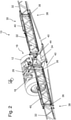
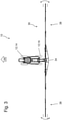
- An embodiment of an agricultural distribution machine 10 according to the invention is from the Figures 1 to 3 out.
- the distribution machine 10 shown here is designed as a self-propelled machine, in which case the invention can also be used or employed in towed or autonomous machines.
- the distribution machine 10 comprises four wheels 12 that support the distribution machine 10, with two opposing wheels 12 forming a chassis or an axle, and with at least the wheels 12 on the front axle 14 or the wheels 12 on the rear axle 16 or the wheels 12 on both axles 14 ; 16 are each arranged to be pivotable or steerable relative to the frame 18, for example about upright axes.
- the axles 14; 16 are also mounted or mounted on a frame 18 carrying the components of the distribution machine 10 .
- the distribution machine 10 comprises a motor 20 driving the distribution machine 10, a cabin 22 and a reservoir 24 for carrying along and providing the respective liquid and/or the granular or granulated substances or their mixtures.
- the frame 18 is assigned a parallelogram 26 that can be adjusted in height relative to the frame 18 by means of actuators. To which a transverse to the direction of travel 28 extending distribution device 30 connects. It should be pointed out once again that the embodiment using a parallelogram 26 represents only one option for attaching the distribution device 30 . It would also be conceivable to attach them directly to the frame 18 . For the sake of simplicity, however, the attachment of the distribution device 30 will be referred to the frame below, although this does not exclude a connection by means of a parallelogram 26 or another intermediate segment or intermediate frame, but the term frame in connection with the attachment of the distribution device 30 is equally applicable also relates to such embodiments.
- the distribution device is divided into several linkage segments 32 and consists of a central part 34 and on the left and right of this via upright axles 36 pivotally mounted side parts 38.
- the side parts 38 in turn are also composed of a plurality of linkage segments 32 which are also arranged pivotably relative to one another by means of upright axes 36.
- the distribution machine 10 shown is composed, for example, of a total of eleven linkage segments 32 which can each be pivoted about upright axes 36 with respect to one another.
- the distribution device 30 or its central part 34 could also be mounted on the frame 18 or on the parallelogram 26 so that it can be pivoted about an upright axis, as a result of which the entire distribution device 30 could also be pivoted accordingly.
- motorized actuators 40 are provided on these, which are controlled or actuated in particular by an electronic control device 42 (cf. 6 ).
- actuators 40 according to the Figures 1 to 3 are hydraulically operated cylinders or linear drives, which are controlled by an electrically operated valve.
- pneumatic and/or electrically operated actuators 40 could also be used.
- the yawing and pitching movements acting on the distribution device 30 (cf. 3 Arrows), which can be detected by sensors, for example, can be counteracted by appropriate control of the actuators 40.
- the motorized actuators 40 can also be provided with damping means or the like in order to counteract corresponding yawing and pitching movements.
- the distribution device 30 can be pivoted about an axis of rotation 44 running in the direction of travel 28 by means of at least one drive element 46 in accordance with a ground contour, in order to achieve the most exact possible adaptation to the respective ground contour or the respective horizon or to achieve the most equal possible distances between to reach the distribution device 30 and the ground contour or to a plant stand.
- the agricultural distribution machine 10 shown here is designed as an agricultural distribution machine 10 towed by a towing vehicle 46, it also being noted here that the invention can also be used self-propelled or autonomous spreading machines or agricultural machines can be used or used.
- the distribution machine 10 is moved over a field 48 by means of a towing vehicle 46, the field 48 having an edge structure 50 composed of several sides, which edge structure 50 also includes several corners 52 at different angles to one another.
- the connection between the distribution machine 10 and the towing vehicle takes place by means of a towing device or a drawbar 54.
- Straight edge structures 50 would also be conceivable edge structures 50 which have curves, or edge structures 50 which have corners 52 and curves.
- the distribution machine 10 also has an axle or a chassis with two wheels 12 that can each be steered, which wheels 12 can be pivoted or steered by means of at least one motorized actuator 40 . It should be noted that, in addition to steering the wheels 12 , it would also be conceivable to steer the distribution machine 10 by means of a pivotable traction device 54 or to steer the distribution machine 10 both by means of the wheels 12 and by means of the traction device 54 .
- the agricultural distribution machine 10 is guided along lanes 56 by the towing vehicle 46 .
- the lanes 56 can be, for example, so-called tramlines.
- lanes 56 would also be conceivable; in particular, the respective lanes 56 can be detected and/or evaluated using lane detection devices 74, for example these could also be stored in control device 42 or corresponding data could be retrieved from a database using control device 42 .
- the respective edge structure 50 In order to achieve the most extensive possible treatment of the arable land 48 depending on the respective lanes 56 and the respective existing edge structures 50, provision is made for the respective edge structure 50 to be measured using a wide variety of contour determination devices 58, such as a laser scanner and/or a camera and/or a camera system and/or is detected by means of a GPS system and/or by means of radar sensors or the like and is transmitted accordingly to the control device 42, or is attached to the distribution machine 10, or is connected to the control device 42.
- the respective edge structures 50 can also be appropriately retrieved or read out from a database by means of the control device 42 .
- sensors 60 mounted in such a way that by means of this the current orientation or relative position 62 is determined.
- An alignment of the distribution device 30 or an alignment of its linkage segments 32 in relation to the edge structure 50 can thus be calculated by means of the control device 42 by means of a corresponding control program, and then the respective motorized actuator 40 or a valve 64 assigned to it can be controlled accordingly and thus the distribution machine 10 or its distribution device 30 or its linkage segments 32 are moved to a desired position.
- the respective motorized actuator 40 is or is actuated accordingly on the basis of the control program and the distribution device 30 and/or the linkage segments 32 are pivoted accordingly.
- the distributor machine 10 can also be steered accordingly by means of the drawbar 54 or by means of the wheels 12 in order to achieve an at least largely parallel and/or right-angled alignment with the existing edge structure 50 by means of the distributor device 30 or by means of the linkage segments 32.
- the distributor machine 10 could also be steered accordingly and the distributor device 30 and/or the linkage segments 32 could be pivoted accordingly.
- the distribution machine 10 can be guided along a definable or a defined lane 56, which means that its wheels 12 and/or its traction device 54 are steered in such a way that they follow the lane 56.
- a control device 42 of the distribution machine 10 A control of the actuators 40 could also be such that the distribution machine 10 respectively Lanes 56 follows, but the distribution device 30 or its linkage segments 32 are respectively pivoted based on the existing edge structure 10 so that the distribution device 30 or its linkage segments 32 follow the edge structure 50 parallel and/or at right angles. This is particularly advantageous when reversing, since the corners and curves or the like are treated over their entire surface by the firmly defined or definable lanes 56, but little or no plants are driven over.
- contour determination devices 58 connected to the distribution machine 10 or to the control device 42 are provided.
- the contour determination devices 58 can correspondingly detect and/or evaluate the respective edge structure 50 and transmit them to the control device 42, but the contour determination devices 58 could also only transmit signals to the control device 42, and then a control program stored in the control device 42 could generate an edge structure 50 accordingly or be evaluated.
- the contour determination device 58 could also be a database or could be connected to a database.
- sensors 60 are provided, e.g. on the distribution machine 10 and/or on the upright axles 36 and/or the actuators 40.
- the sensors 60 can in particular be any type of position sensors, for example angle potentiometers or angle sensors or the like.
- the sensors 60 could also only transmit signals to the control device 42 .
- the corresponding signals can then be converted into corresponding values of the relative positions 62 by means of a control program stored in the control device 42 .
- both Driving movements 68 can be detected, for example, whether the distribution machine 10 or its towing vehicle 46 is moving forwards or backwards or at what speed the distribution machine 10 or its towing vehicle 46 is being moved. It could also be detected whether the distribution machine 10 or its towing vehicle 46 is being accelerated or decelerated.
- Lanes 56 could also be recorded and/or evaluated using additional measuring means 66 or using lane determination devices 74, for example, but lanes 56 could also be transmitted to control device 42 using a GPS system. Likewise, lanes 56 could be stored in a database connected to control device 42 .
- further measuring means 66 could be provided for determining the alignment of distribution machine 10, for example acceleration sensors or yaw rate sensors or gyroscopes or position sensors or the like.
- a valve 64 associated with the respective motorized actuator 40 is then controlled by means of the control device 42, which then controls or actuates the actuator 40 in such a way that the distribution device 30 or the linkage segments 32 or the Distributing machine 10 take a desired position.
- a control program is stored in the control device 42 which, taking into account the detected actual values of the alignment or the relative position and the detected or existing edge structure 50 , performs a calculation for Activation of the motorized actuator 40 is created, with the control program also being able to define corresponding travel speeds of the actuator 40 for this purpose.
- the Traveling speeds could also be made even more precise by taking into account and processing a wide variety of parameters 76, such as current travel movements 68 of the distributor machine 10, i.e. the greater the travel speed of the distributor machine 10, the faster the travel speed of the motorized actuator(s) 40 could be .
- the traversing speeds could also be based on various other parameters 76, so that once again double treatments and/or sub-treatments can be avoided by pivoting too quickly or too slowly.
- the travel speed can be based, for example, on the travel speed of the distribution machine 10 and/or on the basis of the application quantity and/or on the basis of the distance and/or on the basis of the relative positions recorded in each case.
- These parameters 76 can also be recorded, for example, using a wide variety of measuring devices 66 and processed using the control program stored in the control device 42 .
Landscapes
- Life Sciences & Earth Sciences (AREA)
- Engineering & Computer Science (AREA)
- Insects & Arthropods (AREA)
- Pest Control & Pesticides (AREA)
- Wood Science & Technology (AREA)
- Zoology (AREA)
- Environmental Sciences (AREA)
- Guiding Agricultural Machines (AREA)
- Control Of Position, Course, Altitude, Or Attitude Of Moving Bodies (AREA)
Claims (24)
- Épandeur agricole (10) doté d'au moins un châssis (18), d'un réservoir (24) ou de plusieurs réservoirs (24) et d'un dispositif d'épandage (30) destiné à l'épandage de liquides et/ou de matières granuleuses ou granulées, ledit dispositif d'épandage (30) étant agencé de manière mobile sur le châssis (18) et étant divisé en plusieurs segments de rampe (32) qui sont agencés de manière pivotante les uns par rapport aux autres et/ou par rapport au châssis (18) par l'intermédiaire d'axes verticaux (36),ledit épandeur (10) comprenant en outre au moins un train de roulement présentant au moins deux roues (12), et/ou un dispositif de traction (54), lesdites roues (12) et/ou ledit dispositif de traction (54) étant agencés de manière à pouvoir pivoter ou être dirigés par rapport au châssis (18) par l'intermédiaire d'axes verticaux, au moins un actionneur (40) motorisé pouvant être commandé par un dispositif de régulation électronique (42) étant prévu pour le pivotement ou la direction,des capteurs (60) étant associés au dispositif d'épandage (30) et/ou aux segments de rampe (32) et/ou aux axes verticaux (36) et/ou au train de roulement et/ou au dispositif de traction (54) et/ou aux actionneurs (40) pour détecter et transmettre une valeur réelle relative à l'orientation du dispositif d'épandage (30) et/ou des segments de rampe (32) et/ou des axes verticaux et/ou du train de roulement et/ou du dispositif de traction (54) et/ou des actionneurs (40),des dispositifs de détection de contours (58) étant associés à l'épandeur (10) et/ou en liaison avec le dispositif de régulation (42) pour détecter et/ou évaluer une structure périphérique (50) d'une surface à traiter et/ou à traverser par l'épandeur agricole (10), un scanner laser et/ou une caméra et/ou un système de caméra et/ou un capteur radar étant utilisés comme dispositif de détermination de contours (58), et/ou une structure périphérique (50) étant calculée à l'aide d'un rayon de courbure déterminé au moyen d'un programme de commande mémorisé dans le dispositif de régulation (42),et des dispositifs de détermination de voie (74) associés à l'épandeur (10) et/ou en liaison avec le dispositif de régulation (42) étant associés pour détecter et/ou évaluer une voie de circulation (56),caractérisé en ce qu'une commande des actionneurs motorisés (40) s'effectue en fonction d'une structure périphérique (50) existante et d'une voie de circulation existante (56) de telle sorte que les segments de rampe (32) et/ou le dispositif d'épandage (30) présentent une orientation au moins largement parallèle et/ou perpendiculaire à la structure périphérique (50).
- Épandeur agricole selon la revendication 1, caractérisé en ce que ledit au moins un actionneur motorisé (40) du train de roulement et/ou du dispositif de traction (54) est commandé de telle sorte que les roues (12) suivent une voie de circulation (56).
- Épandeur agricole selon la revendication 1 ou 2, caractérisé en ce qu'un capteur d'angle est agencé entre un véhicule de traction (46) et l'épandeur (10) pour détecter l'orientation de l'épandeur (10), et/ou que ledit épandeur (10) présente des capteurs d'angle de braquage (60), et/ou qu'au moins un gyroscope est associé à l'épandeur (10), et/ou qu'au moins un capteur d'accélération est associé à l'épandeur (10).
- Épandeur agricole selon l'une quelconque des revendications précédentes, caractérisé en ce qu'un calcul pour commander lesdits au moins deux actionneurs motorisés (40) s'effectue au moyen d'un programme de commande mémorisé dans le dispositif de régulation (42), lequel programme tient compte des valeurs réelles de l'orientation et de la structure périphérique (50) existante ainsi que de la voie de circulation (56) souhaitée et/ou existante.
- Épandeur agricole selon la revendication 4, caractérisé en ce qu'un programme de commande mémorisé dans le dispositif de régulation (42) permet de calculer la commande dudit au moins un actionneur (40) motorisé du train de roulement ou dudit au moins un actionneur (40) du dispositif d'épandage (30) et/ou de ses segments de rampe (32) en tenant compte du mouvement de marche et de la vitesse de marche de l'épandeur (10).
- Épandeur agricole selon l'une quelconque des revendications précédentes, caractérisé en ce qu'il est réalisé comme épandeur agricole (10) automoteur ou comme épandeur (10) tracté à l'aide d'un véhicule de traction (46) ou comme épandeur (10) autonome.
- Épandeur agricole selon la revendication 6, caractérisé en ce qu'une commande automatisée de la direction d'un véhicule de traction (46) et/ou d'un épandeur (10) automoteur et/ou d'un épandeur (10) autonome s'effectue à l'aide de la structure périphérique (50) existante et/ou de la voie de circulation (56) souhaitée.
- Épandeur agricole selon la revendication 6, caractérisé en ce qu'un affichage des mouvements de direction nécessaires d'un véhicule de traction (46) ou d'un épandeur (10) automoteur s'effectue à l'aide de la structure périphérique (50) existante et/ou de la voie de circulation (56) désirée.
- Épandeur agricole selon l'une quelconque des revendications précédentes, caractérisé en ce qu'une orientation parallèle et/ou perpendiculaire présentent un décalage définissable.
- Épandeur agricole selon l'une quelconque des revendications précédentes, caractérisé en ce qu'un système GPS peut être utilisé comme dispositif de détermination de contour (58) et/ou que des cartes des différentes surfaces arables sont mémorisées dans le dispositif de régulation (42), et/ou que ledit dispositif de régulation (42) lit les structures périphériques (50) respectives à partir d'une banque de données.
- Épandeur agricole selon l'une quelconque des revendications précédentes, caractérisé en ce que le dispositif de détermination de voie (74) est réalisé comme scanner laser et/ou comme caméra et/ou comme système de caméra et/ou comme capteur radar, et/ou que le dispositif de détermination de voie (74) est réalisé comme système GPS, et/ou que le dispositif de régulation (42) lit la voie (56) respective à partir d'une banque de données et/ou qu'une voie (56) est calculée à l'aide d'un rayon de courbure déterminé au moyen d'un programme de commande mémorisé dans le dispositif de régulation (42).
- Épandeur agricole selon l'une quelconque des revendications précédentes, caractérisé en ce qu'une commande des largeurs partielles du dispositif d'épandage (30) s'effectue en fonction d'une direction détectée des segments de rampe (32) et/ou du dispositif d'épandage (30), et en fonction d'une structure périphérique (50) existante, et/ou que les quantités d'épandage des largeurs partielles du dispositif d'épandage (30) sont réglées en fonction de l'orientation détectée et de la structure périphérique (50) existante, et/ou que des modèles de pulvérisation différents sont générés en fonction de l'orientation détectée et de la structure périphérique (50) existante.
- Épandeur agricole selon l'une quelconque des revendications précédentes, caractérisé en ce que la vitesse de déplacement dudit au moins un actionneur (40) est augmentée ou diminuée en fonction de la vitesse de marche et/ou de la quantité d'épandage et/ou de l'orientation actuelle.
- Épandeur agricole selon l'une quelconque des revendications précédentes, caractérisé en ce que le dispositif d'épandage (30) peut être pivoté à la perpendiculaire du sens de marche (28), un pivotement s'effectuant sur la base d'une structure périphérique (50) existante.
- Procédé de commande et/ou de réglage d'un épandeur (10) doté d'au moins un châssis (18), d'un réservoir (24) ou de plusieurs réservoirs (24) et d'un dispositif d'épandage (30) destiné à l'épandage de liquides et/ou de matières granuleuses ou granulées, ledit dispositif d'épandage (30) étant agencé de manière mobile au châssis (18) et divisé en plusieurs segments de rampe (32) qui sont agencés de manière pivotante les uns par rapport aux autres et/ou par rapport au châssis (18) par l'intermédiaire d'axes verticaux, comprenant en outre au moins un train de roulement présentant au moins deux roues (12) et/ou un dispositif de traction (54), lesdites roues (12) et/ou le dispositif de traction (54) étant agencés de manière pivotante ou pouvant être dirigés par rapport au châssis (18) par l'intermédiaire d'axes verticaux, au moins un actionneur motorisé (40) pouvant être commandé par un dispositif de régulation (42) électronique étant respectivement prévu pour le pivotement ou pour la direction
caractérisé par les étapes de procédé :- détection d'une valeur réelle relative à l'orientation des segments de rampe (32) et/ou du dispositif d'épandage (30) et/ou des roues (12) et/ou du dispositif de traction (54) au moyen de ceux-ci et/ou des axes verticaux (36) et/ou des capteurs (60) associés aux actionneurs (40),- détection et évaluation d'une structure périphérique (50) d'une surface à travailler et/ou à traverser par ledit épandeur agricole (10) au moyen de dispositifs de détermination de contour (58) associés audit épandeur (10) et/ou en liaison avec le dispositif de régulation (42), un scanner laser et/ou une caméra et/ou un système de caméra et/ou un capteur radar étant utilisés comme dispositif de détermination de contour (58), et/ou une structure périphérique (50) étant calculée à l'aide d'un rayon de courbure déterminé au moyen d'un programme de commande mémorisé dans le dispositif de régulation (42),- détection et/ou évaluation d'une voie de circulation (56) au moyen des dispositifs de détermination de voie (74) associés à l'épandeur (10) et/ou en liaison avec le dispositif de régulation (42),- commande des actionneurs motorisés (40) en fonction d'une structure périphérique existante (50) et d'une voie de circulation existante (56) de telle sorte que les segments de rampe (32) et/ou le dispositif d'épandage (30) présentent une orientation au moins largement parallèle et/ou perpendiculaire à la structure périphérique (50). - Procédé selon la revendication 15, caractérisé en ce que ledit au moins un actionneur motorisé (40) du train de roulement et/ou du dispositif de traction (54) est commandé de telle sorte que les roues (12) suivent une voie de circulation (56).
- Procédé selon la revendication 15 ou 16, caractérisé en ce que pour détecter l'orientation de l'épandeur (10), un capteur angulaire est agencé entre un véhicule de traction (46) et l'épandeur (10) et/ou ledit épandeur (10) présente des capteurs d'angle de braquage (60) et/ou qu'au moins un gyroscope est associé à l'épandeur (10) et/ou qu'au moins un capteur d'accélération est associé à l'épandeur (10).
- Épandeur agricole selon l'une quelconque des revendications 15 à 17, caractérisé en ce qu'un calcul pour commander lesdits au moins deux actionneurs motorisés (40) s'effectue au moyen d'un programme de commande mémorisé dans le dispositif de régulation (42), les valeurs réelles de l'orientation et de la structure périphérique (50) existante ainsi que de la voie de circulation (56) souhaitée étant prises en compte.
- Épandeur agricole selon l'une quelconque des revendications 15 à 18, caractérisé en ce qu'un programme de commande mémorisé dans le moyen de régulation (42) permet d'effectuer un calcul pour la commande dudit au moins un actionneur motorisé (40) du train de roulement ou dudit au moins un actionneur motorisé (40) du dispositif d'épandage (30) et/ou de ses segments de rampe (32) en tenant compte du mouvement de marche et de la vitesse de marche de l'épandeur (10).
- Épandeur agricole selon l'une quelconque des revendications 15 à 19, caractérisé en ce qu'une commande automatisée de la direction d'un véhicule de traction (46) et/ou d'un épandeur (10) automoteur et/ou d'un épandeur (10) autonome s'effectue à l'aide de la structure périphérique (50) existante et/ou de la voie de circulation (56) souhaitée.
- Procédé selon l'une quelconque des revendications 15 à 20, caractérisé en ce qu'un affichage des mouvements de direction nécessaires d'un véhicule de traction (46) ou d'un épandeur (10) automoteur s'effectue à l'aide de la structure périphérique (50) existante et/ou de la voie de circulation (56) désirée.
- Épandeur agricole selon l'une quelconque des revendications 15 à 21, caractérisé en ce qu'une commande des largeurs partielles du dispositif d'épandage (30) s'effectue en fonction d'une orientation détectée des segments de rampe (32) et/ou du dispositif d'épandage (30), et en fonction d'une structure périphérique (50) existante, et/ou que les quantités d'épandage des largeurs partielles du dispositif d'épandage (30) sont réglées en fonction de l'orientation détectée et de la structure périphérique (50) existante, et/ou que des modèles de pulvérisation différents sont générés en fonction de l'orientation détectée et de la structure périphérique (50) existante.
- Épandeur agricole selon l'une quelconque des revendications 15 à 22, caractérisé en ce que la vitesse de déplacement dudit au moins un actionneur (40) est augmentée ou diminuée en fonction de la vitesse de marche et/ou de la quantité d'épandage et/ou de l'orientation actuelle.
- Épandeur agricole selon l'une quelconque des revendications 15 à 23, caractérisé en ce que le dispositif d'épandage (30) peut être pivoté à la perpendiculaire du sens de marche (28), un pivotement s'effectuant sur la base d'une structure périphérique (50) existante.
Applications Claiming Priority (1)
| Application Number | Priority Date | Filing Date | Title |
|---|---|---|---|
| DE102017122421.1A DE102017122421A1 (de) | 2017-09-27 | 2017-09-27 | Landwirtschaftliche Verteilmaschine und Verfahren zur Steuerung einer derartigen Verteilmaschine |
Publications (2)
| Publication Number | Publication Date |
|---|---|
| EP3469899A1 EP3469899A1 (fr) | 2019-04-17 |
| EP3469899B1 true EP3469899B1 (fr) | 2022-03-16 |
Family
ID=63642689
Family Applications (1)
| Application Number | Title | Priority Date | Filing Date |
|---|---|---|---|
| EP18195135.1A Active EP3469899B1 (fr) | 2017-09-27 | 2018-09-18 | Machine d'épandage agricole et procédé de commande d'une telle machine d'épandage |
Country Status (2)
| Country | Link |
|---|---|
| EP (1) | EP3469899B1 (fr) |
| DE (1) | DE102017122421A1 (fr) |
Families Citing this family (1)
| Publication number | Priority date | Publication date | Assignee | Title |
|---|---|---|---|---|
| DE102019108730A1 (de) * | 2019-04-03 | 2020-10-08 | Horsch Leeb Application Systems Gmbh | Technik zur Erzeugung eines Geländeprofils mit einer Landmaschine |
Family Cites Families (12)
| Publication number | Priority date | Publication date | Assignee | Title |
|---|---|---|---|---|
| DE19948407A1 (de) * | 1999-11-04 | 2001-04-12 | Amazonen Werke Dreyer H | Landwirtschaftliche Verteilmaschine |
| DE102005019238A1 (de) | 2005-04-26 | 2006-11-09 | Amazonen-Werke H. Dreyer Gmbh & Co. Kg | Landwirtschaftliche Verteilmaschine |
| DE102006015204A1 (de) | 2006-03-30 | 2007-10-18 | Claas Selbstfahrende Erntemaschinen Gmbh | Verfahren zur Erstellung eines Routenplans für landwirtschaftliche Maschinensysteme |
| DE102010041885A1 (de) * | 2010-10-01 | 2012-04-05 | Deere & Company | Kombination aus einem Zugfahrzeug und einem Gerät |
| DE102011002035A1 (de) * | 2011-04-14 | 2012-10-18 | Amazonen-Werke H. Dreyer Gmbh & Co. Kg | Verteilergestänge |
| US8942893B2 (en) * | 2012-09-07 | 2015-01-27 | Trimble Navigation Limited | Predictive boom shape adjustment |
| DE102013214469A1 (de) | 2013-07-24 | 2015-01-29 | Horsch Leeb Application Systems Gmbh | Landwirtschaftliche Verteilmaschine mit Verteilvorrichtung und System zur Steuerung der Verteilvorrichtung |
| EP2837285B1 (fr) | 2013-08-09 | 2021-07-07 | Lemken GmbH & Co. KG | Rampe de pulvérisation d'un pulvérisateur agricole |
| EP2835050B1 (fr) | 2013-08-09 | 2020-10-07 | Lemken GmbH & Co. KG | Pulvérisateur agricole comprenant une rampe d'pulvérisation |
| DE102014102040A1 (de) | 2014-02-18 | 2015-08-20 | Amazonen-Werke H. Dreyer Gmbh & Co. Kg | Landwirtschaftliche Arbeitsmaschine mit Teilbreitensteuerung |
| DE102014111231A1 (de) | 2014-08-07 | 2016-02-11 | Amazonen-Werke H. Dreyer Gmbh & Co. Kg | Verfahren zur Korrektur in einem Speicher eines Arbeitsrechners gespeicherter Positionsdaten |
| US10420276B2 (en) * | 2015-02-24 | 2019-09-24 | The Toro Company | Sprayer with automatically controlled laterally and angularly displaceable spray boom assembly |
-
2017
- 2017-09-27 DE DE102017122421.1A patent/DE102017122421A1/de active Pending
-
2018
- 2018-09-18 EP EP18195135.1A patent/EP3469899B1/fr active Active
Also Published As
| Publication number | Publication date |
|---|---|
| EP3469899A1 (fr) | 2019-04-17 |
| DE102017122421A1 (de) | 2019-03-28 |
Similar Documents
| Publication | Publication Date | Title |
|---|---|---|
| EP3772879B1 (fr) | Véhicule porteur agricole autonome | |
| EP3058820B1 (fr) | Procede de commande et/ou de reglage de mouvement d'un dispositif de distribution agricole | |
| EP2022329A2 (fr) | Dispositif de pulvérisation mobile doté d'une tige de pulvérisation et procédé de réglage de ses buses de pulvérisation | |
| EP2011921A2 (fr) | Dispositif de fraisage de route automobile, en particulier grande fraiseuse | |
| DE102018108025A1 (de) | Landwirtschaftliches Fahrzeug | |
| EP3469898B1 (fr) | Machine d'épandage agricole et procédé de commande d'une telle machine d'épandage | |
| DE102019129206B4 (de) | Selbstfahrende und/oder mittels Zugfahrzeug gezogene Landmaschine und Verfahren zur Steuerung und/oder Regelung einer Höhenlage eines Verteilgestänges einer derartigen Landmaschine | |
| EP3732945B1 (fr) | Technique de la génération d'un profil de terrain à l'aide d'une machine agricole | |
| EP3466257B1 (fr) | Machine d'épandage agricole et procédé de commande d'une telle machine d'épandage | |
| EP3804516B1 (fr) | Machine d'épandage agricole, de préférence pulvérisateur ou distributeur d'engrais | |
| EP3766319B1 (fr) | Appareil de travail agricole destiné au traitement du sol | |
| EP4052550A1 (fr) | Dispositif de compensation de la suspension latérale pour la viticulture | |
| EP3912468B1 (fr) | Procédé de commande et/ou de réglage du mouvement d'un dispositif d'épandage agricole | |
| EP3469899A1 (fr) | Machine d'épandage agricole et procédé de commande d'une telle machine d'épandage | |
| DE102020106738A1 (de) | Kompensationssystem für eine Landmaschine, sowie Verteilmaschine und Verfahren zur Kompensation von Bodenunebenheiten für eine Landmaschine | |
| EP3469897B1 (fr) | Machine d'épandage agricole et procédé de commande d'une telle machine d'épandage | |
| EP3895532B1 (fr) | Système pour une machine agricole de travail, procédé de détermination d'une position des éléments de travail, ainsi que machine agricole de travail | |
| EP4014732B1 (fr) | Machine agricole à épandre et procédé de commande et/ou de régulation d'une machine agricole à épandre | |
| WO2023222478A1 (fr) | Machine de travail agricole à conduite autonome | |
| WO2022161904A1 (fr) | Véhicule porteur agricole autonome, et combinaison de machines agricoles autonomes | |
| EP3434088B1 (fr) | Dispositif agricole tracté | |
| EP4331356A1 (fr) | Machine de répartition agricole dotée d'une rampe de pulvérisation et procédé de commande de la position d'une telle rampe de pulvérisation | |
| EP4364546A1 (fr) | Procédé, dispositif de commande et système de direction pour la direction automatisée d'un véhicule agricole ainsi que véhicule agricole | |
| DE102022129149A1 (de) | Steuer- und/oder Regelsystem sowie Verfahren zur Steuerung und/oder Regelung eines landwirtschaftlichen Fahrzeug | |
| EP4453682A1 (fr) | Système de configuration et procédé de mise en oeuvre d'une machine de travail agricole, et machine de travail agricole |
Legal Events
| Date | Code | Title | Description |
|---|---|---|---|
| PUAI | Public reference made under article 153(3) epc to a published international application that has entered the european phase |
Free format text: ORIGINAL CODE: 0009012 |
|
| STAA | Information on the status of an ep patent application or granted ep patent |
Free format text: STATUS: THE APPLICATION HAS BEEN PUBLISHED |
|
| AK | Designated contracting states |
Kind code of ref document: A1 Designated state(s): AL AT BE BG CH CY CZ DE DK EE ES FI FR GB GR HR HU IE IS IT LI LT LU LV MC MK MT NL NO PL PT RO RS SE SI SK SM TR |
|
| AX | Request for extension of the european patent |
Extension state: BA ME |
|
| STAA | Information on the status of an ep patent application or granted ep patent |
Free format text: STATUS: REQUEST FOR EXAMINATION WAS MADE |
|
| 17P | Request for examination filed |
Effective date: 20191014 |
|
| RBV | Designated contracting states (corrected) |
Designated state(s): AL AT BE BG CH CY CZ DE DK EE ES FI FR GB GR HR HU IE IS IT LI LT LU LV MC MK MT NL NO PL PT RO RS SE SI SK SM TR |
|
| RAP1 | Party data changed (applicant data changed or rights of an application transferred) |
Owner name: HORSCH LEEB APPLICATION SYSTEMS GMBH |
|
| GRAP | Despatch of communication of intention to grant a patent |
Free format text: ORIGINAL CODE: EPIDOSNIGR1 |
|
| STAA | Information on the status of an ep patent application or granted ep patent |
Free format text: STATUS: GRANT OF PATENT IS INTENDED |
|
| INTG | Intention to grant announced |
Effective date: 20211125 |
|
| GRAS | Grant fee paid |
Free format text: ORIGINAL CODE: EPIDOSNIGR3 |
|
| GRAA | (expected) grant |
Free format text: ORIGINAL CODE: 0009210 |
|
| STAA | Information on the status of an ep patent application or granted ep patent |
Free format text: STATUS: THE PATENT HAS BEEN GRANTED |
|
| AK | Designated contracting states |
Kind code of ref document: B1 Designated state(s): AL AT BE BG CH CY CZ DE DK EE ES FI FR GB GR HR HU IE IS IT LI LT LU LV MC MK MT NL NO PL PT RO RS SE SI SK SM TR |
|
| REG | Reference to a national code |
Ref country code: GB Ref legal event code: FG4D Free format text: NOT ENGLISH |
|
| REG | Reference to a national code |
Ref country code: CH Ref legal event code: EP Ref country code: DE Ref legal event code: R096 Ref document number: 502018009093 Country of ref document: DE |
|
| REG | Reference to a national code |
Ref country code: IE Ref legal event code: FG4D Free format text: LANGUAGE OF EP DOCUMENT: GERMAN |
|
| REG | Reference to a national code |
Ref country code: AT Ref legal event code: REF Ref document number: 1475252 Country of ref document: AT Kind code of ref document: T Effective date: 20220415 |
|
| REG | Reference to a national code |
Ref country code: LT Ref legal event code: MG9D |
|
| REG | Reference to a national code |
Ref country code: NL Ref legal event code: MP Effective date: 20220316 |
|
| PG25 | Lapsed in a contracting state [announced via postgrant information from national office to epo] |
Ref country code: SE Free format text: LAPSE BECAUSE OF FAILURE TO SUBMIT A TRANSLATION OF THE DESCRIPTION OR TO PAY THE FEE WITHIN THE PRESCRIBED TIME-LIMIT Effective date: 20220316 Ref country code: RS Free format text: LAPSE BECAUSE OF FAILURE TO SUBMIT A TRANSLATION OF THE DESCRIPTION OR TO PAY THE FEE WITHIN THE PRESCRIBED TIME-LIMIT Effective date: 20220316 Ref country code: NO Free format text: LAPSE BECAUSE OF FAILURE TO SUBMIT A TRANSLATION OF THE DESCRIPTION OR TO PAY THE FEE WITHIN THE PRESCRIBED TIME-LIMIT Effective date: 20220616 Ref country code: LT Free format text: LAPSE BECAUSE OF FAILURE TO SUBMIT A TRANSLATION OF THE DESCRIPTION OR TO PAY THE FEE WITHIN THE PRESCRIBED TIME-LIMIT Effective date: 20220316 Ref country code: HR Free format text: LAPSE BECAUSE OF FAILURE TO SUBMIT A TRANSLATION OF THE DESCRIPTION OR TO PAY THE FEE WITHIN THE PRESCRIBED TIME-LIMIT Effective date: 20220316 Ref country code: BG Free format text: LAPSE BECAUSE OF FAILURE TO SUBMIT A TRANSLATION OF THE DESCRIPTION OR TO PAY THE FEE WITHIN THE PRESCRIBED TIME-LIMIT Effective date: 20220616 |
|
| PG25 | Lapsed in a contracting state [announced via postgrant information from national office to epo] |
Ref country code: LV Free format text: LAPSE BECAUSE OF FAILURE TO SUBMIT A TRANSLATION OF THE DESCRIPTION OR TO PAY THE FEE WITHIN THE PRESCRIBED TIME-LIMIT Effective date: 20220316 Ref country code: GR Free format text: LAPSE BECAUSE OF FAILURE TO SUBMIT A TRANSLATION OF THE DESCRIPTION OR TO PAY THE FEE WITHIN THE PRESCRIBED TIME-LIMIT Effective date: 20220617 Ref country code: FI Free format text: LAPSE BECAUSE OF FAILURE TO SUBMIT A TRANSLATION OF THE DESCRIPTION OR TO PAY THE FEE WITHIN THE PRESCRIBED TIME-LIMIT Effective date: 20220316 |
|
| PG25 | Lapsed in a contracting state [announced via postgrant information from national office to epo] |
Ref country code: NL Free format text: LAPSE BECAUSE OF FAILURE TO SUBMIT A TRANSLATION OF THE DESCRIPTION OR TO PAY THE FEE WITHIN THE PRESCRIBED TIME-LIMIT Effective date: 20220316 |
|
| PG25 | Lapsed in a contracting state [announced via postgrant information from national office to epo] |
Ref country code: SM Free format text: LAPSE BECAUSE OF FAILURE TO SUBMIT A TRANSLATION OF THE DESCRIPTION OR TO PAY THE FEE WITHIN THE PRESCRIBED TIME-LIMIT Effective date: 20220316 Ref country code: SK Free format text: LAPSE BECAUSE OF FAILURE TO SUBMIT A TRANSLATION OF THE DESCRIPTION OR TO PAY THE FEE WITHIN THE PRESCRIBED TIME-LIMIT Effective date: 20220316 Ref country code: RO Free format text: LAPSE BECAUSE OF FAILURE TO SUBMIT A TRANSLATION OF THE DESCRIPTION OR TO PAY THE FEE WITHIN THE PRESCRIBED TIME-LIMIT Effective date: 20220316 Ref country code: PT Free format text: LAPSE BECAUSE OF FAILURE TO SUBMIT A TRANSLATION OF THE DESCRIPTION OR TO PAY THE FEE WITHIN THE PRESCRIBED TIME-LIMIT Effective date: 20220718 Ref country code: ES Free format text: LAPSE BECAUSE OF FAILURE TO SUBMIT A TRANSLATION OF THE DESCRIPTION OR TO PAY THE FEE WITHIN THE PRESCRIBED TIME-LIMIT Effective date: 20220316 Ref country code: EE Free format text: LAPSE BECAUSE OF FAILURE TO SUBMIT A TRANSLATION OF THE DESCRIPTION OR TO PAY THE FEE WITHIN THE PRESCRIBED TIME-LIMIT Effective date: 20220316 Ref country code: CZ Free format text: LAPSE BECAUSE OF FAILURE TO SUBMIT A TRANSLATION OF THE DESCRIPTION OR TO PAY THE FEE WITHIN THE PRESCRIBED TIME-LIMIT Effective date: 20220316 |
|
| PG25 | Lapsed in a contracting state [announced via postgrant information from national office to epo] |
Ref country code: PL Free format text: LAPSE BECAUSE OF FAILURE TO SUBMIT A TRANSLATION OF THE DESCRIPTION OR TO PAY THE FEE WITHIN THE PRESCRIBED TIME-LIMIT Effective date: 20220316 Ref country code: IS Free format text: LAPSE BECAUSE OF FAILURE TO SUBMIT A TRANSLATION OF THE DESCRIPTION OR TO PAY THE FEE WITHIN THE PRESCRIBED TIME-LIMIT Effective date: 20220716 Ref country code: AL Free format text: LAPSE BECAUSE OF FAILURE TO SUBMIT A TRANSLATION OF THE DESCRIPTION OR TO PAY THE FEE WITHIN THE PRESCRIBED TIME-LIMIT Effective date: 20220316 |
|
| REG | Reference to a national code |
Ref country code: DE Ref legal event code: R097 Ref document number: 502018009093 Country of ref document: DE |
|
| PLBE | No opposition filed within time limit |
Free format text: ORIGINAL CODE: 0009261 |
|
| STAA | Information on the status of an ep patent application or granted ep patent |
Free format text: STATUS: NO OPPOSITION FILED WITHIN TIME LIMIT |
|
| PG25 | Lapsed in a contracting state [announced via postgrant information from national office to epo] |
Ref country code: DK Free format text: LAPSE BECAUSE OF FAILURE TO SUBMIT A TRANSLATION OF THE DESCRIPTION OR TO PAY THE FEE WITHIN THE PRESCRIBED TIME-LIMIT Effective date: 20220316 |
|
| 26N | No opposition filed |
Effective date: 20221219 |
|
| PG25 | Lapsed in a contracting state [announced via postgrant information from national office to epo] |
Ref country code: SI Free format text: LAPSE BECAUSE OF FAILURE TO SUBMIT A TRANSLATION OF THE DESCRIPTION OR TO PAY THE FEE WITHIN THE PRESCRIBED TIME-LIMIT Effective date: 20220316 |
|
| PG25 | Lapsed in a contracting state [announced via postgrant information from national office to epo] |
Ref country code: MC Free format text: LAPSE BECAUSE OF FAILURE TO SUBMIT A TRANSLATION OF THE DESCRIPTION OR TO PAY THE FEE WITHIN THE PRESCRIBED TIME-LIMIT Effective date: 20220316 |
|
| REG | Reference to a national code |
Ref country code: CH Ref legal event code: PL |
|
| GBPC | Gb: european patent ceased through non-payment of renewal fee |
Effective date: 20220918 |
|
| REG | Reference to a national code |
Ref country code: BE Ref legal event code: MM Effective date: 20220930 |
|
| PG25 | Lapsed in a contracting state [announced via postgrant information from national office to epo] |
Ref country code: LU Free format text: LAPSE BECAUSE OF NON-PAYMENT OF DUE FEES Effective date: 20220918 |
|
| PG25 | Lapsed in a contracting state [announced via postgrant information from national office to epo] |
Ref country code: LI Free format text: LAPSE BECAUSE OF NON-PAYMENT OF DUE FEES Effective date: 20220930 Ref country code: IT Free format text: LAPSE BECAUSE OF FAILURE TO SUBMIT A TRANSLATION OF THE DESCRIPTION OR TO PAY THE FEE WITHIN THE PRESCRIBED TIME-LIMIT Effective date: 20220316 Ref country code: IE Free format text: LAPSE BECAUSE OF NON-PAYMENT OF DUE FEES Effective date: 20220918 Ref country code: FR Free format text: LAPSE BECAUSE OF NON-PAYMENT OF DUE FEES Effective date: 20220930 Ref country code: CH Free format text: LAPSE BECAUSE OF NON-PAYMENT OF DUE FEES Effective date: 20220930 |
|
| PG25 | Lapsed in a contracting state [announced via postgrant information from national office to epo] |
Ref country code: BE Free format text: LAPSE BECAUSE OF NON-PAYMENT OF DUE FEES Effective date: 20220930 |
|
| PG25 | Lapsed in a contracting state [announced via postgrant information from national office to epo] |
Ref country code: GB Free format text: LAPSE BECAUSE OF NON-PAYMENT OF DUE FEES Effective date: 20220918 |
|
| PG25 | Lapsed in a contracting state [announced via postgrant information from national office to epo] |
Ref country code: HU Free format text: LAPSE BECAUSE OF FAILURE TO SUBMIT A TRANSLATION OF THE DESCRIPTION OR TO PAY THE FEE WITHIN THE PRESCRIBED TIME-LIMIT; INVALID AB INITIO Effective date: 20180918 |
|
| PG25 | Lapsed in a contracting state [announced via postgrant information from national office to epo] |
Ref country code: CY Free format text: LAPSE BECAUSE OF FAILURE TO SUBMIT A TRANSLATION OF THE DESCRIPTION OR TO PAY THE FEE WITHIN THE PRESCRIBED TIME-LIMIT Effective date: 20220316 |
|
| PG25 | Lapsed in a contracting state [announced via postgrant information from national office to epo] |
Ref country code: MK Free format text: LAPSE BECAUSE OF FAILURE TO SUBMIT A TRANSLATION OF THE DESCRIPTION OR TO PAY THE FEE WITHIN THE PRESCRIBED TIME-LIMIT Effective date: 20220316 |
|
| PG25 | Lapsed in a contracting state [announced via postgrant information from national office to epo] |
Ref country code: TR Free format text: LAPSE BECAUSE OF FAILURE TO SUBMIT A TRANSLATION OF THE DESCRIPTION OR TO PAY THE FEE WITHIN THE PRESCRIBED TIME-LIMIT Effective date: 20220316 |
|
| PG25 | Lapsed in a contracting state [announced via postgrant information from national office to epo] |
Ref country code: MT Free format text: LAPSE BECAUSE OF FAILURE TO SUBMIT A TRANSLATION OF THE DESCRIPTION OR TO PAY THE FEE WITHIN THE PRESCRIBED TIME-LIMIT Effective date: 20220316 |
|
| REG | Reference to a national code |
Ref country code: DE Ref legal event code: R082 Ref document number: 502018009093 Country of ref document: DE Representative=s name: BENNINGER, JOHANNES, DIPL.-ING., DE |
|
| REG | Reference to a national code |
Ref country code: AT Ref legal event code: MM01 Ref document number: 1475252 Country of ref document: AT Kind code of ref document: T Effective date: 20230918 |
|
| PG25 | Lapsed in a contracting state [announced via postgrant information from national office to epo] |
Ref country code: AT Free format text: LAPSE BECAUSE OF NON-PAYMENT OF DUE FEES Effective date: 20230918 |
|
| PG25 | Lapsed in a contracting state [announced via postgrant information from national office to epo] |
Ref country code: AT Free format text: LAPSE BECAUSE OF NON-PAYMENT OF DUE FEES Effective date: 20230918 |
|
| PGFP | Annual fee paid to national office [announced via postgrant information from national office to epo] |
Ref country code: DE Payment date: 20250919 Year of fee payment: 8 |
|
| REG | Reference to a national code |
Ref country code: DE Ref legal event code: R081 Ref document number: 502018009093 Country of ref document: DE Owner name: HORSCH LEEB APPLICATION SYSTEMS SE & CO. KG, DE Free format text: FORMER OWNER: HORSCH LEEB APPLICATION SYSTEMS GMBH, 94405 LANDAU, DE |
|
| PGFP | Annual fee paid to national office [announced via postgrant information from national office to epo] |
Ref country code: AT Payment date: 20260410 Year of fee payment: 5 |