EP3469986A1 - Synchronisierungsverfahren eines magnetischen lokalisierungssystems - Google Patents
Synchronisierungsverfahren eines magnetischen lokalisierungssystems Download PDFInfo
- Publication number
- EP3469986A1 EP3469986A1 EP18199815.4A EP18199815A EP3469986A1 EP 3469986 A1 EP3469986 A1 EP 3469986A1 EP 18199815 A EP18199815 A EP 18199815A EP 3469986 A1 EP3469986 A1 EP 3469986A1
- Authority
- EP
- European Patent Office
- Prior art keywords
- synchronization
- magnetic fields
- oscillator
- alternating magnetic
- devices
- Prior art date
- Legal status (The legal status is an assumption and is not a legal conclusion. Google has not performed a legal analysis and makes no representation as to the accuracy of the status listed.)
- Granted
Links
Images


Classifications
-
- A—HUMAN NECESSITIES
- A61—MEDICAL OR VETERINARY SCIENCE; HYGIENE
- A61B—DIAGNOSIS; SURGERY; IDENTIFICATION
- A61B5/00—Measuring for diagnostic purposes; Identification of persons
- A61B5/06—Devices, other than using radiation, for detecting or locating foreign bodies ; Determining position of diagnostic devices within or on the body of the patient
- A61B5/061—Determining position of a probe within the body employing means separate from the probe, e.g. sensing internal probe position employing impedance electrodes on the surface of the body
- A61B5/062—Determining position of a probe within the body employing means separate from the probe, e.g. sensing internal probe position employing impedance electrodes on the surface of the body using magnetic field
-
- G—PHYSICS
- G01—MEASURING; TESTING
- G01C—MEASURING DISTANCES, LEVELS OR BEARINGS; SURVEYING; NAVIGATION; GYROSCOPIC INSTRUMENTS; PHOTOGRAMMETRY OR VIDEOGRAMMETRY
- G01C25/00—Manufacturing, calibrating, cleaning, or repairing instruments or devices referred to in the other groups of this subclass
-
- G—PHYSICS
- G01—MEASURING; TESTING
- G01R—MEASURING ELECTRIC VARIABLES; MEASURING MAGNETIC VARIABLES
- G01R33/00—Arrangements or instruments for measuring magnetic variables
- G01R33/0023—Electronic aspects, e.g. circuits for stimulation, evaluation, control; Treating the measured signals; calibration
-
- G—PHYSICS
- G01—MEASURING; TESTING
- G01R—MEASURING ELECTRIC VARIABLES; MEASURING MAGNETIC VARIABLES
- G01R33/00—Arrangements or instruments for measuring magnetic variables
- G01R33/02—Measuring direction or magnitude of magnetic fields or magnetic flux
-
- G—PHYSICS
- G01—MEASURING; TESTING
- G01V—GEOPHYSICS; GRAVITATIONAL MEASUREMENTS; DETECTING MASSES OR OBJECTS; TAGS
- G01V3/00—Electric or magnetic prospecting or detecting; Measuring magnetic field characteristics of the earth, e.g. declination, deviation
- G01V3/08—Electric or magnetic prospecting or detecting; Measuring magnetic field characteristics of the earth, e.g. declination, deviation operating with magnetic or electric fields produced or modified by objects or geological structures or by detecting devices
- G01V3/081—Electric or magnetic prospecting or detecting; Measuring magnetic field characteristics of the earth, e.g. declination, deviation operating with magnetic or electric fields produced or modified by objects or geological structures or by detecting devices the magnetic field is produced by the objects or geological structures
-
- G—PHYSICS
- G06—COMPUTING OR CALCULATING; COUNTING
- G06F—ELECTRIC DIGITAL DATA PROCESSING
- G06F1/00—Details not covered by groups G06F3/00 - G06F13/00 and G06F21/00
- G06F1/04—Generating or distributing clock signals or signals derived directly therefrom
- G06F1/12—Synchronisation of different clock signals provided by a plurality of clock generators
-
- H—ELECTRICITY
- H04—ELECTRIC COMMUNICATION TECHNIQUE
- H04B—TRANSMISSION
- H04B7/00—Radio transmission systems, i.e. using radiation field
- H04B7/24—Radio transmission systems, i.e. using radiation field for communication between two or more posts
- H04B7/26—Radio transmission systems, i.e. using radiation field for communication between two or more posts at least one of which is mobile
- H04B7/2662—Arrangements for Wireless System Synchronisation
- H04B7/2671—Arrangements for Wireless Time-Division Multiple Access [TDMA] System Synchronisation
- H04B7/2678—Time synchronisation
-
- H—ELECTRICITY
- H04—ELECTRIC COMMUNICATION TECHNIQUE
- H04J—MULTIPLEX COMMUNICATION
- H04J3/00—Time-division multiplex systems
- H04J3/02—Details
- H04J3/06—Synchronising arrangements
- H04J3/0635—Clock or time synchronisation in a network
- H04J3/0638—Clock or time synchronisation among nodes; Internode synchronisation
- H04J3/0658—Clock or time synchronisation among packet nodes
- H04J3/0661—Clock or time synchronisation among packet nodes using timestamps
- H04J3/0667—Bidirectional timestamps, e.g. NTP or PTP for compensation of clock drift and for compensation of propagation delays
-
- G—PHYSICS
- G06—COMPUTING OR CALCULATING; COUNTING
- G06F—ELECTRIC DIGITAL DATA PROCESSING
- G06F1/00—Details not covered by groups G06F3/00 - G06F13/00 and G06F21/00
- G06F1/04—Generating or distributing clock signals or signals derived directly therefrom
- G06F1/08—Clock generators with changeable or programmable clock frequency
-
- H—ELECTRICITY
- H04—ELECTRIC COMMUNICATION TECHNIQUE
- H04L—TRANSMISSION OF DIGITAL INFORMATION, e.g. TELEGRAPHIC COMMUNICATION
- H04L7/00—Arrangements for synchronising receiver with transmitter
- H04L7/0008—Synchronisation information channels, e.g. clock distribution lines
- H04L7/0012—Synchronisation information channels, e.g. clock distribution lines by comparing receiver clock with transmitter clock
-
- H—ELECTRICITY
- H04—ELECTRIC COMMUNICATION TECHNIQUE
- H04L—TRANSMISSION OF DIGITAL INFORMATION, e.g. TELEGRAPHIC COMMUNICATION
- H04L7/00—Arrangements for synchronising receiver with transmitter
- H04L7/0016—Arrangements for synchronising receiver with transmitter correction of synchronization errors
Definitions
- the field of the invention relates to the magnetic location of devices between them. More particularly, the invention relates to a synchronization method of a magnetic locating system.
- a magnetic locating system can be based on the modulation of alternating magnetic fields, especially in amplitude, to determine a relative position and a relative orientation between a device comprising an emitter of alternating magnetic fields and a device comprising a receiver of alternating magnetic fields.
- a relative location may correspond to a calculation of the position and orientation of one of the devices relative to the other of the devices.
- connection between the two devices can be wired.
- a synchronous detection principle is used by the device receiving the alternating magnetic fields emitted by the device emitting the alternating magnetic fields, in particular by the use of a pilot signal emitted by the device emitting the alternating magnetic fields which makes it possible to time the reception of the magnetic fields alternating with the emission of the alternating magnetic fields: the emission and the reception are then triggered simultaneously.
- a central computer comprising a single oscillator synchronously controlling the transmission and reception of the alternating magnetic fields.
- a disadvantage of the wired link is the constraint relative to the physical link between the two devices, or between the two devices and a central computer, which can for example limit the movements between the two devices. There is therefore a need to be free of the wired link, for example, to allow better ergonomics / flexibility of use of the magnetic tracking system.
- a solution proposed by the patent US8,121,812 is to set up a time multiplexing emitted magnetic fields, consisting of three transmission windows and one synchronization.
- the frequencies of the magnetic fields emitted are also constrained: the duration of the transmission windows must correspond to an integer multiple of the period of each emitted magnetic field.
- This solution has the disadvantage of limiting the frequencies used to implement the magnetic location and generally slowing down the magnetic localization system related to the temporal multiplexing of the magnetic fields.
- this solution also has the disadvantage of limiting a phase ambiguity removal that ⁇ near, this does not allow to detect a phase shift, sign of a presence of a potential artefact hindering the magnetic location .
- An artifact corresponds to an outside disturbance of the alternating magnetic fields.
- the invention aims to remedy all or part of the aforementioned drawbacks.
- the aim of the invention is to propose a synchronization which makes it possible in particular to maintain identical the phases and frequencies of the emitted alternating magnetic field modulations with reference signals used for the demodulation of the received alternating magnetic fields, with a view to implementing a magnetic location.
- the invention also relates to a magnetic localization method comprising a step of implementing the synchronization method as described, and a relative location step between the first and second devices by taking into account data from the device. transmission and reception of alternative magnetic fields.
- An object of the invention relates to a synchronization method of a magnetic locating system for synchronizing two distinct oscillators which will be used to clock a device for transmitting and receiving alternating magnetic fields, these alternative magnetic fields being intended for to be used to determine a relative location between first and second devices of the magnetic locating system which will be described in more detail below.
- the magnetic locating system comprises a first device 100 ( figure 1 ) and a second device 200 ( figure 2 ).
- the magnetic locating system is configured to establish at least one relative location between the first and second devices 100, 200, especially from alternative magnetic fields propagated between the first and second devices 100, 200.
- data derived from, that is to say relating to, alternating magnetic fields, in particular transmitted and received may be used / taken into account to determine a relative location between the first and second devices 100, 200.
- relative location between the first and second devices 100, 200 means the location of one of the first and second devices 100, 200 relative to the other of the first and second devices 100, 200.
- the location may correspond in the field of the present invention to a particular positioning and / or orientation of one of the first and second devices 100, 200 with respect to the other of the first and second devices 100, 200.
- the first device 100 comprises an oscillator 101, a time counter 102 clocked by the oscillator 101 of the first device 100, and a radiocommunication module 103.
- the second device 200 comprises an oscillator 201, a time counter 202 clocked by the oscillator 201 of the second device 200, and a radiocommunication module 203.
- oscillator 101, 201 is meant an electronic component whose function is to produce a periodic signal for clocking other electronic components, such as for example a time counter, a frequency synthesizer, etc.
- time counter 102, 202 is meant an electronic component whose function is to provide a time stamp.
- the timing of a timer is implemented by the oscillator to which it is connected.
- the time counter 102 of the first device 100 comprises a clock input clk_1 connected to a clocking output S1 of the oscillator 101 of the first device 100 (FIG. figure 1 ).
- the time counter 202 of the second device 200 includes a clock input clk_2 connected to a clocking output S2 of the oscillator 201 of the second device 200 (FIG. figure 2 ).
- the clock inputs can provide pulses to count in the context of time counters.
- time stamp By “timestamp”, called “timestamp” in English language, we mean a piece of information that makes it possible to associate temporal information with an event.
- a time stamp can represent a quantity of time elapsed since a reference time, or a date and a time.
- radiocommunication modules 103, 203 are configured to enter wireless communication to exchange data.
- a radiocommunication module in the sense of the present description is therefore a radio-waves transmitter-receiver module.
- the magnetic locating system is such that one of the first and second devices 100, 200 is able to move relative to the other of the first and second devices 100, 200. Moreover, it does not exist. wired communication link between the first and second devices 100, 200.
- the magnetic locating system also comprises the device for transmitting and receiving 104, 204 of alternating magnetic fields connected to the oscillators 101, 201 of the first and second devices 100, 200.
- This transmitting and receiving device 104, 204 is configured to allow propagation of alternating magnetic fields between the first device 100 and the second device 200, in particular with a view to implementing at least one relative magnetic locating step between the first device 100 and the second device 200 by taking into account counts data from the transmitting and receiving device 104, 204 as will be described below.
- This device for transmitting and receiving 104, 204 of alternating magnetic fields is formed in particular in two parts, one of which is integrated in the first device 100 and the other in the second device 200.
- the transmitter 104 of alternating magnetic fields may be clocked by one of the oscillators (that of the first device 100 in the example illustrated in FIG. figure 1 ) and the receiver 204 of alternating magnetic fields can then be clocked by the other of the oscillators (that of the second device 200 in the example illustrated in FIG. figure 2 ). It is therefore clear that there is a problem of synchronization to solve if we want to improve the operation of the magnetic location system since the transmitter 104 and the receiver 204 will be clocked by separate oscillators.
- the transmitter 104 of alternating magnetic fields may comprise frequency synthesizers 104a, 104b, 104c, also called direct digital synthesizers and known under the acronym DDS corresponding in English to "Direct Digital Synthesizer".
- Each frequency synthesizer 104a, 104b, 104c of the emitter 104 of alternating magnetic fields may comprise a clock input clk_3 connected to the clocking output S1 of the oscillator 101 of the first device 100, an input En1 of setpoint C1 specifying how often it should work, and an entry En2 to receive a start command O1.
- each frequency synthesizer 104a, 104b, 104c drives a coil 105a, 105b, 105c of the transmitter 104 for generating a corresponding alternating magnetic field according to a suitable control of the associated frequency synthesizer.
- each coil 105a, 105b, 105c is excited with a frequency of its own by a frequency synthesizer 104a, 104b, 104c associated with said coil 105a, 105b, 105c.
- the receiver 204 of alternating magnetic fields may comprise frequency synthesizers 204a, 204b, 204c.
- Each frequency synthesizer 204a, 204b, 204c of the receiver 204 of alternating magnetic fields may comprise a clock input clk_4 connected to the clock output S2 of the oscillator 201 of the second device 200, an entry En3 of setpoint C2 specifying it on which frequency it should operate, and an input En4 for receiving a start command 02.
- Each frequency synthesizer 204a, 204b, 204c can provide a reference modulation frequency, for example a phase and a quadrature to a demodulation unit 210 alternative magnetic fields received.
- This demodulation unit 210 is connected to coils 205a, 205b, 205c (called “receiver coils”) of the receiver 204 of alternating magnetic fields intended to receive / receive the corresponding alternating magnetic fields emitted by the coils of the field transmitter 104.
- the phase and the quadrature make it possible to go back to two pieces of information namely the amplitude and the phase of the demodulated signal on all of the receiver coils 205a, 205b, 205c.
- the unit of demodulation 210 makes it possible to perform phase and quadrature synchronous detections to find, on the side of the receiver 204 of alternating magnetic fields, the amplitudes and the phases of the magnetic fields received from information supplied by the frequency synthesizers 204a, 204b, 204c of the receiver 204 of alternating magnetic fields.
- the inputs En3 of setpoint C2, En4 of start command 02 and clock clk_4 of frequency synthesizer 104a are represented in FIG. figure 2 but the same principle applies to other frequency synthesizers 204b, 204c.
- the setpoints C1 are different for each frequency synthesizer 104a, 104b, 104c of the emitter 104 of alternating magnetic fields in order to differentiate the frequencies of the magnetic fields emitted by the different coils 105a, 105b, 105c of the transmitter 104. alternative magnetic fields. It is then understood that each instruction C1 is different from the other instructions C1. Furthermore, each instruction C2 is identical to one of the setpoints C1, the setpoints C1 can be chosen by the first device 100, and transmitted to the second device 200 by radio communication between the radiocommunication modules 103, 203 of the first and second devices 100, 200 It will be understood that each instruction C2 is different from the other instructions C2.
- the first device 100 comprises the transmitter 104 of alternating magnetic fields
- the second device 200 comprises the receiver 204 of alternating magnetic fields.
- this embodiment is preferred because the receiver 204 of alternating magnetic fields (or more generally the second device 200) is generally mobile, implying that the second device 200 is more compact: it integrates, for example, for example a source of energy and the reception of alternative magnetic fields that consume less energy than their emission.
- the synchronization method of the magnetic locating system comprises a synchronization of, that is to say a synchronization step E1 configured to synchronize the oscillators 101, 201 of the first and second devices 100, 200 by adjusting the operation of the counter time 202 of the second device 200 to the operation of the time counter 102 of the first device 100. Notably, this adjustment is performed by slaving the oscillator 201 of the second device 200.
- servocontrolling the oscillator 201 of the second device 200 is meant that its operation will be modified voluntarily due to the desired adjustment between the time counters, while the oscillator 101 of the first device 100 will preferably remain at the same operating frequency: the frequency of the oscillator 201 can be modified then that that of the oscillator 101 is preferentially not. Adjusting the operation of one time counter to another allows them to tend to give, for the same instant, similar / identical timestamps according to a suitable residual offset, typically less than one microsecond.
- the stability of the synchronization can be such that the difference in time stamping between the time counters 102, 202 of the first and second devices 100, 200 can be between -100ns and 100ns (this being a function of the resolution of the counters time or noise associated with the operation of radio communication chips used in the radiocommunication modules for processing the radiocommunications involved in the synchronization as will be described below) when the synchronization is effective.
- Synchronization stability means that it can be reproducible at each start of the magnetic locating system, and therefore at each oscillator synchronization following startup.
- the adjustment of the operation of the time counter 202 of the second device 200 to the operation of the time counter 102 of the first device 100 makes it possible to operate the time counters according to the same time base (for example in date and time) all in synchronizing the oscillators, this has the corollary that the synchronization step is such that it allows to operate the time counters on the same time base.
- the time base of the oscillator 101 of the first device 100 is noted b 1
- the time base of the oscillator 201 of the second device 200 is noted b 2.
- Synchronization is here material because it acts directly on the operation of one of the oscillators. By choosing suitable components, the accuracy of the synchronization is satisfactory in the desired application of the magnetic location.
- the adjustment described has the advantage, on the one hand, of obtaining a dating system common to first and second devices 100, 200 each having its own time counter clocked by an associated oscillator, and, d on the other hand, to synchronize the oscillators (transmitter side and receiver side) at operating frequencies, which results in the possibility of implementing a magnetic localization by mastering the original phase of alternative signals used to emit the magnetic fields alternating as well as the original phase of alternative signals generated by the receiver coils: the limitation to ⁇ near is raised.
- the alternating signals are used to excite the coils 105a, 105b, 105c, said transmitting coils, from which the emission of the alternating magnetic fields results.
- the receiver coils 205a, 205b, 205c are excited by excitation fields originating from the alternating magnetic fields emitted, from which the generation, for each receiver coil, of an alternating signal in view to achieve magnetic localization.
- the synchronization makes it possible in particular to maintain identical the phases and frequencies of the alternating magnetic field modulations emitted with reference signals used for the demodulation of the received alternating magnetic fields.
- the reference signals are constructed on the receiver side 204 using the oscillator 201 of the second device 200 synchronized with that of the first device 100: one then has the same phase of origin and the same frequency for each of the first and second devices 100, 200.
- the reference signals can decode the alternating signals generated by the receiver coils 205a, 205b, 205c and then implement, from the decoded data, the magnetic location.
- radiocommunication modules 103, 203 are used to transmit data making it possible to participate in the synchronization since the first and second devices 100, 200 can not communicate by wire connection between them.
- the synchronization step E1 may comprise a transmission step E1-1 of first timestamps h 1 t i b 1 , determined by the time counter 102 of the first device 100, the second device 200 by radio communication between the radiocommunication modules 103, 203 of the first and second devices 100, 200.
- the first timestamps are therefore transmitted to the radiocommunication module 203 of the second device 200 by the radiocommunication module 103 of the first device 100.
- h 1 t i b 1 i represents a positive integer greater than or equal to 1 and making it possible to identify the corresponding first time stamp
- b 1 refers to the time base of the time counter 102 of the first device 100.
- the second device 200 receives, in particular successively and in particular at regular intervals, the first timestamps h 1 t i b 1 it can use to slave its oscillator 201.
- the synchronization step E1 also comprises a step E1-2 determination of second timestamps h 2 t i b 2 by the time counter 202 of the second device 200.
- the synchronization step E1 further comprises a step of E1-3 control of the oscillator 201 of the second device 200 using, that is to say, taking into account, the first timestamps h 1 t i b 1 and the second timestamps h 2 t i b 2 .
- This servo-control step E1-3 is implemented by the second device 200.
- the different first timestamps may be used successively in association with corresponding second time stamps to modify the operation of the oscillator 201 of the second device 200. for example by accelerating or slowing it down, so as to tend to obtain a common dating system and the synchronization of the oscillators 101, 201 of the first and second devices 100, 200.
- Such a use of timestamps is advantageous because it makes it easier to synchronize the oscillators since the time counters are themselves clocked by said oscillators.
- the servo-control step E1-3 can be such that the operation of the oscillator 201 of the second device 200 will be modified to act on the timing of the time counter 202 of the second device 200 in order to stall the operation said time counter 202 of the second device 200 on that of the first device 100 from which it will also result in the synchronization of the oscillators 101, 201 of the first and second devices 100, 200.
- the servo-control step E1 -3 may comprise at least one or more steps E1-3-1 for determining a servocontrol setpoint C3 (FIG.
- each instruction C3 servocontrol is determined using a (i.e. from a) time differential ⁇ t ( figure 2 ) taking into account one of the first timestamps (represented by the reference h1 to the figure 2 ) and one of the second time stamps (represented by the reference h2 to the figure 2 ).
- the second device 200 may comprise a differential generator 206 ( figure 2 ) taking as input two timestamps (here represented h1 and h2) and generating at output the time differential noted ⁇ t .
- the synchronization step may include a step of determining the time differential ⁇ t.
- the - or each - servo setpoint is preferably determined so as to act on the time difference between the first and second time counters 102, 202.
- the - or each - Servo control is preferably determined so as to reduce the time difference between the first and second time counters 102, 202, or so as to maintain the absolute value of this difference below a predetermined threshold.
- the predetermined threshold is then chosen according to the application for which it is considered that the oscillators 101, 201 of the first and second devices 100, 200 are synchronized.
- the adjustment of the operation of the time counter 202 of the second device 200 to the operation of the time counter 102 of the first device 100 can be implemented using a comparison first and second timestamps h 1 t i b 1 , h 2 t i b 2 related to each other.
- the idea here is to determine one of the first time stamps h 1 t i b 1 , according to the time base of the time counter 102 of the first device 100, and one of the second time stamps h 2 t i b 2 , according to the time base of the time counter 202 of the second device 200, at close or similar times to be able to compare them in order to control the operation of the oscillator 201 of the second device 200 by the adjustment mentioned above.
- An effective solution to implement this idea proposes to use the fact that the delay of transmission of a signal from the radiocommunication module 103 of the first device 100 to the radiocommunication module 203 of the second device 200, as well as the transition between a low level (0) and a high level (1) of this signal are sufficiently deterministic to make it possible to compare a time stamp generated during the transmission of a signal on the side of the first device 100 with a time stamp generated during the reception of this same signal on the side of the second device 200.
- This presents the advantage of obtaining coherent values to be provided as inputs in the context of servocontrolling the oscillator of the second device 200.
- each first timestamp h 1 t i b 1 determining said first time stamp h 1 t i b 1 when sending a corresponding synchronization signal SYNC, and for each second time stamp h 2 t i b 2 , the determination of said second time stamp is done upon receipt of a corresponding synchronization signal.
- the second device 200 does not have the first time stamp h 1 t i b 1 associated with comparing with said one of the second timestamps h 2 t i b 2 to determine the time differential ⁇ t mentioned above.
- the two timestamps that we are trying to compare are called "linked" or "corresponding".
- synchronization signal consecutive to another is meant the synchronization signal which arrives directly after without interposition of an intermediate synchronization signal.
- previous synchronization signal of another synchronization signal is meant the synchronization signal which arrives directly before without interposition of an intermediate synchronization signal.
- each synchronization signal received by the radiocommunication module 203 of the second device 200, and for which the second device 200 has one of the second timestamps h 2 t i b 2 determined by the time counter 202 of the second device 200 upon receipt of a previous synchronization signal to said received SYNC synchronization signal causes the implementation of one of the determination steps E1-3-1 of a servo setpoint C3 for which the time differential ⁇ t is obtained by taking into account one of the first time stamps h1 extracted from said received synchronization signal SYNC and said second time stamp h2 determined by the time counter 202 of the second device 200 upon reception of said previous synchronization signal to said SYNC synchronization signal received.
- the first time stamp it contains is extracted in order to obtain the time differential.
- the servo-control step E1-3 can comprise ( figure 3 ) steps E1-3-1 for determining a servo control setpoint C3 of the oscillator 201 of the second device 200 each followed by an application step E1-3-2 of said servocontrol setpoint C3 to oscillator 201 of the second device 200.
- Each control setpoint is then determined using the time differential taking into account one of the first time stamps h1, also noted h 1 t i b 1 , and one of the second h2 timestamps, also noted h 2 t i b 2 , respectively corresponding to a timestamp of the transmission and a timestamp of the reception of the same synchronization signal SYNC.
- each step E1-3-1 for determining a servo setting of the oscillator 201 of the second device 200 is triggered by receiving one of the synchronization signals SYNC.
- the synchronization signals SYNC are emitted at regular intervals so as to enable the application of the servocontrol setpoint C3 determined between the reception of the synchronization signal having triggered the determination of said servocontrol setpoint C3 and the reception of a synchronization signal consecutive to that which triggered the determination of said setpoint of servo C3.
- each servo command C3 is applied before the reception by the radiocommunication module 203 of a synchronization signal consecutive to the signal having triggered the determination of said servo command C3.
- the second device 200 in order to establish the time differential, the second device 200 must first have the second time stamp corresponding to the first time stamp extracted from the received synchronization signal so that said first and second time stamps correspond to those determined when transmitting and receiving the same synchronization signal preceding said received synchronization signal.
- the very first synchronization signal transmitted will not include useful data, but will be sent to allow the generation of the very first of the first timestamps and the very first of the second timestamps.
- the synchronization will be effective when the time differential evoked previously remains in a predetermined range, for example between -100ns and + 100ns.
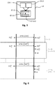
- the figure 4 schematically illustrates the operation of the transmission and reception of synchronization signals.
- figure 4 it is represented two vertical lines, on the left of the vertical line on the left it is represented what happens on the side of the first device 100, on the right of the vertical line on the right it is represented what happens on the side of the second device 200, and between the two vertical lines is represented the synchronization signals.
- the cycle is such that the second device 200 can extract the value of h 1 t j b 1 of the synchronization signal received, and can determine the time differential noted ⁇ t taking into account h 1 t j b 1 and h 2 t j b 2 then at his disposal.
- This time differential ⁇ t can then be used to determine the servo setpoint C3 and apply it to the oscillator 201 of the second device 200 ( figure 2 ) before a new synchronization signal is received.
- synchronization can be continued by repeating the previously mentioned cycle especially with i up to n, where n is a positive integer depending on the number of iterations of the cycle.
- the value of n depends on the control law which makes it possible to combine a good precision for the synchronization and a transient (delay to implement the synchronization) not too long not to penalize the application of magnetic localization.
- n can be limited by the application requirement: a maximum of a few seconds of transient, or n being equal to, or be of the order of 1000, considering 200 iterations of the cycle per second.
- the latter is transmitted to the radiocommunication module 103 of the first device 100 in order to be sent thereafter to the second device 200 via a corresponding synchronization signal.
- the servo-control step E1-3 of the oscillator 201 of the second device 200 can comprise, as for example illustrated in the embodiment of the figure 2 , a use of a loop filter 207.
- the role of the loop filter 207 is to develop each C3 servo setpoint of the second oscillator 201 whose purpose is to reduce the time difference of dating between the time counters, or to maintain its absolute value below a predetermined threshold in order to ensure the desired synchronization.
- the loop filter 107 takes as input the time differential, and outputs a servo setpoint C3 of the oscillator 201 of the second device 200.
- This predetermined threshold is a function of the application, for example for a frequency of sinusoidal signals emitted of the order of 20kHz, and a phase shift tolerated of plus or minus 1 degree, the predetermined threshold may be equal to 140ns. In this sense, it is said that the loop filter 207 retroacts on the frequency of the oscillator 201 of the second device 200. For example, when the absolute value of the time differential is below the predetermined threshold, it is considered that the synchronization of the oscillators 101, 201 is effective.
- Each control setpoint C3 may be a control voltage of the oscillator 201 of the second device 200.
- the oscillator 201 of the second device 200 may then be a voltage controlled oscillator or "VCO" (for English “Voltage Controlled Oscillator ").
- VCO voltage controlled oscillator
- the use of a voltage-controlled oscillator has the advantage of obtaining a very fine granularity on the frequency of the enslaved oscillator, and thus a very fine stability in fine of the frequency of the receiver 204, where appropriate.
- transmitter 104 clocked by the slave oscillator.
- the oscillator 201 of the second device 200 provided with the receiver 204 which is slaved because it allows for example, if the magnetic locating system comprises several second devices 201 each associated with a corresponding receiver 204, to easily synchronize the oscillators connected to the receivers 204 to the same oscillator connected to the transmitter 104.
- the loop filter 207 implements a proportional-integral control law, also denoted PI, which makes it possible to regulate the oscillator 201 of the second device 200 via the servocontrol instructions C3 successively determined and applied.
- PI proportional-integral control law
- Such a control law has the advantage of slaving the phase and the frequency of the enslaved oscillator, thus facilitating phase and frequency synchronization of the oscillators 101, 201 of the first and second devices 100, 200 to allow subsequent control.
- the phase of the alternating magnetic fields emitted and received. Indeed, once the synchronization obtained, both the frequency and the phase of the receiver 204 can be aligned with those of the transmitter 104.
- This time differential ⁇ t can be determined by a step of determining the time differential during the synchronization step E1.
- This temporal differential ⁇ t can be a differential between said one of the first time stamps h 1 t i b 1 and said one of the second timestamps h 2 t i b 2 , the differential can then be obtained by subtracting said one of the second timestamps h 2 t i b 2 audit one of the first timestamps h 1 t i b 1 , Or vice versa.
- the time differential ⁇ t also takes into account an offset parameter ("offset" in English).
- the time differential ⁇ t can be obtained by subtracting one of the first timestamps h 1 t i b 1 , said one second timestamps h 2 t i b 2 corresponding and the offset parameter.
- the advantage of taking into account the offset parameter is to take into account the fact that there is a delay between the moment of generation of said one of the first timestamps h 1 t i b 1 and said one of the second timestamps h 2 t i b 2 , this delay being in particular due to the electronics used to enable the generation of these time stamps and to the propagation time of the signal between the radiocommunication modules 103, 203 (this propagation time can on the other hand be considered negligible and not taken into account in the offset parameter). In the context of magnetic localization, this shift parameter can be neglected because it remains generally constant.
- the differential generator 206 of the figure 2 may include an additional input (not shown) providing the offset parameter to said differential generator 206.
- the invention can also relate to a magnetic locating method, for example as illustrated in the embodiment according to the invention.
- figure 5 comprising a step E100 of implementing the synchronization method as described, and a relative positioning step E101 between the first and second devices 100, 200 taking into account data from the transmitting and receiving device 104, 204 of alternative magnetic fields.
- These data can be exploited for example in the manner of the teaching of the article of RAAB et al. entitled "Magnetic Position and Orientation Tracking System" published in IEEE Transactions on Aerospace and Electronic Systems, Vol. AES-15, No. 5 September 1979 pages 709 to 718 .
- the location step 101 is implemented while the oscillators are synchronized. The resulting benefits derive from those described above.
- the magnetic locating method may comprise, as illustrated in Figures 1, 2 and 5 after adjusting the operation of the time counter 202 of the second device 200 to the operation of the time counter 102 of the first device 100 (i.e., when the oscillators 101, 201 are synchronized), a comparison step E102 of a time set point C4 with data h3, h4 coming from the time counters 102, 202 of the first and second devices 100, 200.
- the magnetic locating method may comprise a start step E103 of the transmission and reception device 104, 204 of alternating magnetic fields triggered as a function of the result of the comparison step E102.
- the start step E103 can be triggered as soon as the time setpoint C4 is reached by the data h3 and h4: the time setpoint C4 corresponds in this example to a timestamp value.
- the first device 100 may comprise a comparator 106 having inputs H3 and C4, and possibly outputting the start command O1 transmitted on the inputs En2 of the frequency synthesizers 104a, 104b, 104c of
- the second device 200 may comprise a comparator 208 having as inputs h4 and C4 and outputting, if necessary, the start command 02 to be transmitted on the inputs En4 of the frequency synthesizers 204a, 204b. 204c of the receiver 204.
- time set point C4 can be selected by the first device 100 and transmitted to the second device 200 by radio communication between the radiocommunication modules 103, 203 of the first and second devices 100, 200.
- the location step E101 is implemented in particular after the start-up step of the transmission and reception device 104, 204 or, if appropriate, after the steps of FIG. activating the receiver 204 and transmitter 104.
- the synchronization step E1 is triggered before activating the emitter 104 of alternating magnetic fields and the receiver 204 of alternating magnetic fields, and is kept active during the operation of the emitter 104 of alternating magnetic fields and receiver 204 of alternating magnetic fields.
- This has the advantage of maintaining a synchronization during the localization, and not only at the time of its start to avoid the phenomenon of sliding phase as the exchanges between the radiocommunication modules are maintained.
- the invention also relates to a magnetic localization system in particular as described above and adapted to the synchronization method and / or the location method as described above.
- the magnetic locating system may comprise program code instructions for performing the steps of the synchronization method and / or the magnetic locating method as described.
- the latter in addition to all that has been said previously in connection with the magnetic locating system, can be configured to allow synchronization of the oscillators 101, 201 of the first and second devices 100, 200 by adjustment, enslaving the oscillator 201 of the second device 200, the operation of the time counter 202 of the second device 200 to the operation of the time counter 102 of the first device 100.
- This has the advantage of allowing the synchronization mentioned above.
- the magnetic locating system may comprise a plurality of second devices 200. Those skilled in the art are then able to adapt the system synchronization method. magnetic location to allow synchronization of all the oscillators 201 of the second devices 200 to the oscillator 101 of the first device 100. This has the advantage of applying the present invention in the context of the location of a plurality of second devices 200 each having a receiver 204 of alternating magnetic fields with respect to the first device 100 comprising the transmitter 104 of alternating magnetic fields.
- the radiocommunication channel used to send the synchronization signals may also allow the sending of data, for example data relating to the magnetic fields received, to the part of the magnetic locating system which comprises the magnetic field emitter in order to implement the relative location between the first device and the second device.
- the communication channel may also allow the sending of data relating to start instructions of the magnetic locating device.
- the synchronization method, the localization method and the magnetic localization system described above may have an industrial application in the field of magnetic localization in the medical sector.
- the magnetic locating system can be at six degrees of freedom (in positions and angles) and can be used in the medical field where one seeks for example to follow the movement of the second device 200 in a body by relative to the first device 100 located outside this body, and in particular fixed relative to this body.
- the first device 100 comprising the transmitter 104 is fixed outside the body of a patient and the second device 200 comprising the receiver 204 can move on the surface of the body or inside the body.
- the methods of synchronization and magnetic location and the magnetic location system can be used in any field using the use of a magnetic location system.
- the first device 100 when using the magnetic locating system, whether in the context of the synchronization method or in the context of the magnetic locating method, the first device 100 remains at a distance from the second device 200 (for example less than meter) adapted to the intensity of the magnetic moment emitted by the transmitter 104 and the sensitivity of the receiver 204 to allow a suitable magnetic location: in other words it is necessary that the magnetic fields emitted can be correctly received by the receiver 204.
- a six-dimensional magnetic localization system has been mentioned above, the invention can also be applied to any smaller magnetic location system (for example a 5-dimensional system, in the case where the receiver has only four dimensions). a single receiving coil and in which the angle along the axis of the coil can not be solved).
Landscapes
- Engineering & Computer Science (AREA)
- Physics & Mathematics (AREA)
- General Physics & Mathematics (AREA)
- Life Sciences & Earth Sciences (AREA)
- Remote Sensing (AREA)
- Computer Networks & Wireless Communication (AREA)
- Signal Processing (AREA)
- Condensed Matter Physics & Semiconductors (AREA)
- Health & Medical Sciences (AREA)
- Theoretical Computer Science (AREA)
- General Engineering & Computer Science (AREA)
- Geophysics (AREA)
- Pathology (AREA)
- General Life Sciences & Earth Sciences (AREA)
- Environmental & Geological Engineering (AREA)
- Manufacturing & Machinery (AREA)
- Radar, Positioning & Navigation (AREA)
- Human Computer Interaction (AREA)
- Electromagnetism (AREA)
- Biophysics (AREA)
- Geology (AREA)
- Biomedical Technology (AREA)
- Heart & Thoracic Surgery (AREA)
- Medical Informatics (AREA)
- Molecular Biology (AREA)
- Surgery (AREA)
- Animal Behavior & Ethology (AREA)
- General Health & Medical Sciences (AREA)
- Public Health (AREA)
- Veterinary Medicine (AREA)
- Synchronisation In Digital Transmission Systems (AREA)
Applications Claiming Priority (1)
| Application Number | Priority Date | Filing Date | Title |
|---|---|---|---|
| FR1759637A FR3072469B1 (fr) | 2017-10-13 | 2017-10-13 | Procede de synchronisation d'un systeme de localisation magnetique |
Publications (2)
| Publication Number | Publication Date |
|---|---|
| EP3469986A1 true EP3469986A1 (de) | 2019-04-17 |
| EP3469986B1 EP3469986B1 (de) | 2021-11-03 |
Family
ID=61223985
Family Applications (1)
| Application Number | Title | Priority Date | Filing Date |
|---|---|---|---|
| EP18199815.4A Active EP3469986B1 (de) | 2017-10-13 | 2018-10-11 | Synchronisierungsmethode für ein magnetisches ortungssystem |
Country Status (3)
| Country | Link |
|---|---|
| US (1) | US11632169B2 (de) |
| EP (1) | EP3469986B1 (de) |
| FR (1) | FR3072469B1 (de) |
Citations (2)
| Publication number | Priority date | Publication date | Assignee | Title |
|---|---|---|---|---|
| US20160011013A1 (en) * | 2014-07-11 | 2016-01-14 | Sixense Entertainment, Inc. | Method And Apparatus For Synchronizing a Transmitter and Receiver in a Magnetic Tracking System |
| US20170131424A1 (en) * | 2003-10-04 | 2017-05-11 | SeeScan, Inc. | Sondes & methods for use with buried line locator systems |
Family Cites Families (14)
| Publication number | Priority date | Publication date | Assignee | Title |
|---|---|---|---|---|
| IL122578A (en) | 1997-12-12 | 2000-08-13 | Super Dimension Ltd | Wireless six-degree-of-freedom locator |
| US7366754B2 (en) * | 2001-06-29 | 2008-04-29 | Thomson Licensing | Multi-media jitter removal in an asynchronous digital home network |
| US6774624B2 (en) | 2002-03-27 | 2004-08-10 | Ge Medical Systems Global Technology Company, Llc | Magnetic tracking system |
| US7015859B2 (en) | 2003-11-14 | 2006-03-21 | General Electric Company | Electromagnetic tracking system and method using a three-coil wireless transmitter |
| US7873491B2 (en) | 2004-06-08 | 2011-01-18 | Alken, Inc. | AC magnetic tracking system with non-coherency between sources and sensors |
| US20050285591A1 (en) | 2004-06-08 | 2005-12-29 | Higgins Robert F | AC magnetic tracking system employing wireless field source |
| US7539889B2 (en) * | 2005-12-30 | 2009-05-26 | Avega Systems Pty Ltd | Media data synchronization in a wireless network |
| WO2008156653A1 (en) | 2007-06-13 | 2008-12-24 | Alken Inc., Dba Polhemus | Ac magnetic tracking system with phase locking |
| US8121812B2 (en) | 2007-09-14 | 2012-02-21 | Alken Inc. | AC magnetic tracking with phase disambiguation |
| US8450997B2 (en) | 2009-04-28 | 2013-05-28 | Brown University | Electromagnetic position and orientation sensing system |
| US9474465B2 (en) | 2012-06-27 | 2016-10-25 | Ascension Technology Corporation | System and method for magnetic position tracking |
| US10362107B2 (en) * | 2014-09-04 | 2019-07-23 | Liqid Inc. | Synchronization of storage transactions in clustered storage systems |
| EP3500911B1 (de) * | 2016-08-22 | 2023-09-27 | Magic Leap, Inc. | Anzeigevorrichtung mit erweiterter realität mit tiefenlernsensoren |
| US10534454B2 (en) * | 2018-02-02 | 2020-01-14 | Sony Interactive Entertainment Inc. | Head-mounted display to controller clock synchronization over EM field |
-
2017
- 2017-10-13 FR FR1759637A patent/FR3072469B1/fr not_active Expired - Fee Related
-
2018
- 2018-10-11 EP EP18199815.4A patent/EP3469986B1/de active Active
- 2018-10-12 US US16/158,690 patent/US11632169B2/en active Active
Patent Citations (2)
| Publication number | Priority date | Publication date | Assignee | Title |
|---|---|---|---|---|
| US20170131424A1 (en) * | 2003-10-04 | 2017-05-11 | SeeScan, Inc. | Sondes & methods for use with buried line locator systems |
| US20160011013A1 (en) * | 2014-07-11 | 2016-01-14 | Sixense Entertainment, Inc. | Method And Apparatus For Synchronizing a Transmitter and Receiver in a Magnetic Tracking System |
Also Published As
| Publication number | Publication date |
|---|---|
| FR3072469A1 (fr) | 2019-04-19 |
| US11632169B2 (en) | 2023-04-18 |
| US20190113585A1 (en) | 2019-04-18 |
| EP3469986B1 (de) | 2021-11-03 |
| FR3072469B1 (fr) | 2019-11-01 |
Similar Documents
| Publication | Publication Date | Title |
|---|---|---|
| JP7145957B2 (ja) | 衛星航法用の受信機における疑似距離を補正するための方法 | |
| EP3603235B1 (de) | Uwb-lokalisierungsverfahren mit hilfskanalsynchronisation | |
| WO2013117670A1 (fr) | Procédé de synchronisation de mesures de temps réalisées dans un réseau de radiocommunication aux fins de géolocalisation | |
| EP0190730A1 (de) | Einrichtung zur Dreifachtaktverteilung, wobei jedes Taktsignal ein Synchronisationssignal enthält | |
| EP2938002B1 (de) | Vorrichtung und Verfahren zur Bestimmung der Eingangszeit eines UWB-Signals | |
| EP3171195B1 (de) | Verfahren zur lokalisierung einer bake | |
| EP3910363A1 (de) | Methode zur lokalisierung eines verbundenen objekts durch phasendifferenzen des eingangs in ein lpwa-netzwerk | |
| EP2909944B1 (de) | Uwb empfänger mit zeitverschiebungskorrektur | |
| FR3051929A1 (fr) | Circuit d'arbitrage temporel | |
| EP3469986B1 (de) | Synchronisierungsmethode für ein magnetisches ortungssystem | |
| US20170033919A1 (en) | Frequency control data synchronization | |
| EP2653887B1 (de) | Funksystem für den Gebrauch in einer Funkanlage mit Mehrfachhöhenmessung | |
| EP2979378B1 (de) | Schnittstellen-architektur zwischen einer digitalen untereinheit und einer radio-untereinheit | |
| EP4105673B1 (de) | Methode zur einschätzung der eigenschaften eines gepulsten ultrabreitbandsignals, das von mehreren antennen ausgesendet wird | |
| EP2388620B1 (de) | Vorrichtung zur Phasendiskriminierung und zur Diskriminierung der Phasenänderung eines Signals | |
| EP4606075A1 (de) | Verfahren zur schätzung mindestens eines parameters aus einem zeitvorlauf und einem frequenzversatz zwischen einer ersten und einer zweiten kommunikationsvorrichtung | |
| EP2156569B1 (de) | Verfahren zur verarbeitung von ultrabreitbandigen gleichgerichteten abgetasteten signalen | |
| FR2680579A1 (fr) | Procede et dispositif de mesure de la distance d'un objet en vol. | |
| FR3030950A1 (fr) | Procede de mesure de la distance separant deux nœuds mobiles ayant etabli une liaison radioelectrique uwb | |
| FR3060763A1 (fr) | Procede et systeme de localisation d'un emetteur radiofrequence | |
| FR3101157A1 (fr) | Mesure de distance basée sur phase avec temps d’acquisition constant | |
| EP1400028B1 (de) | Mehrzweigigdiskriminatormodul für ein navigationssystem | |
| EP4434235A1 (de) | Verfahren und zugehörige ausrüstung zur synchronisierung eines drahtlosen ferndatenübertragungssystems | |
| FR2923613A1 (fr) | Procede pour reduire dans un radar sar bistatique la transmission de donnees entre porteurs par technique de focalisation a l'emission | |
| WO2026003481A1 (en) | A system and method for time transfer |
Legal Events
| Date | Code | Title | Description |
|---|---|---|---|
| PUAI | Public reference made under article 153(3) epc to a published international application that has entered the european phase |
Free format text: ORIGINAL CODE: 0009012 |
|
| STAA | Information on the status of an ep patent application or granted ep patent |
Free format text: STATUS: REQUEST FOR EXAMINATION WAS MADE |
|
| 17P | Request for examination filed |
Effective date: 20181011 |
|
| AK | Designated contracting states |
Kind code of ref document: A1 Designated state(s): AL AT BE BG CH CY CZ DE DK EE ES FI FR GB GR HR HU IE IS IT LI LT LU LV MC MK MT NL NO PL PT RO RS SE SI SK SM TR |
|
| AX | Request for extension of the european patent |
Extension state: BA ME |
|
| GRAP | Despatch of communication of intention to grant a patent |
Free format text: ORIGINAL CODE: EPIDOSNIGR1 |
|
| STAA | Information on the status of an ep patent application or granted ep patent |
Free format text: STATUS: GRANT OF PATENT IS INTENDED |
|
| INTG | Intention to grant announced |
Effective date: 20210528 |
|
| RIC1 | Information provided on ipc code assigned before grant |
Ipc: A61B 5/06 20060101AFI20210517BHEP Ipc: A61B 5/107 20060101ALI20210517BHEP Ipc: A61B 5/00 20060101ALI20210517BHEP Ipc: G01C 25/00 20060101ALI20210517BHEP Ipc: G01R 33/00 20060101ALI20210517BHEP Ipc: G01V 3/08 20060101ALI20210517BHEP |
|
| RIN1 | Information on inventor provided before grant (corrected) |
Inventor name: JOSSELIN, VINCENT Inventor name: BERTRAND, FRANCOIS Inventor name: ALOUI, SAIFEDDINE Inventor name: PAULET, JEROME |
|
| GRAS | Grant fee paid |
Free format text: ORIGINAL CODE: EPIDOSNIGR3 |
|
| GRAA | (expected) grant |
Free format text: ORIGINAL CODE: 0009210 |
|
| STAA | Information on the status of an ep patent application or granted ep patent |
Free format text: STATUS: THE PATENT HAS BEEN GRANTED |
|
| AK | Designated contracting states |
Kind code of ref document: B1 Designated state(s): AL AT BE BG CH CY CZ DE DK EE ES FI FR GB GR HR HU IE IS IT LI LT LU LV MC MK MT NL NO PL PT RO RS SE SI SK SM TR |
|
| REG | Reference to a national code |
Ref country code: GB Ref legal event code: FG4D Free format text: NOT ENGLISH |
|
| REG | Reference to a national code |
Ref country code: AT Ref legal event code: REF Ref document number: 1443254 Country of ref document: AT Kind code of ref document: T Effective date: 20211115 Ref country code: CH Ref legal event code: EP |
|
| REG | Reference to a national code |
Ref country code: DE Ref legal event code: R096 Ref document number: 602018026012 Country of ref document: DE |
|
| REG | Reference to a national code |
Ref country code: IE Ref legal event code: FG4D Free format text: LANGUAGE OF EP DOCUMENT: FRENCH |
|
| REG | Reference to a national code |
Ref country code: LT Ref legal event code: MG9D |
|
| REG | Reference to a national code |
Ref country code: NL Ref legal event code: MP Effective date: 20211103 |
|
| REG | Reference to a national code |
Ref country code: AT Ref legal event code: MK05 Ref document number: 1443254 Country of ref document: AT Kind code of ref document: T Effective date: 20211103 |
|
| PG25 | Lapsed in a contracting state [announced via postgrant information from national office to epo] |
Ref country code: RS Free format text: LAPSE BECAUSE OF FAILURE TO SUBMIT A TRANSLATION OF THE DESCRIPTION OR TO PAY THE FEE WITHIN THE PRESCRIBED TIME-LIMIT Effective date: 20211103 Ref country code: LT Free format text: LAPSE BECAUSE OF FAILURE TO SUBMIT A TRANSLATION OF THE DESCRIPTION OR TO PAY THE FEE WITHIN THE PRESCRIBED TIME-LIMIT Effective date: 20211103 Ref country code: FI Free format text: LAPSE BECAUSE OF FAILURE TO SUBMIT A TRANSLATION OF THE DESCRIPTION OR TO PAY THE FEE WITHIN THE PRESCRIBED TIME-LIMIT Effective date: 20211103 Ref country code: BG Free format text: LAPSE BECAUSE OF FAILURE TO SUBMIT A TRANSLATION OF THE DESCRIPTION OR TO PAY THE FEE WITHIN THE PRESCRIBED TIME-LIMIT Effective date: 20220203 Ref country code: AT Free format text: LAPSE BECAUSE OF FAILURE TO SUBMIT A TRANSLATION OF THE DESCRIPTION OR TO PAY THE FEE WITHIN THE PRESCRIBED TIME-LIMIT Effective date: 20211103 |
|
| PG25 | Lapsed in a contracting state [announced via postgrant information from national office to epo] |
Ref country code: IS Free format text: LAPSE BECAUSE OF FAILURE TO SUBMIT A TRANSLATION OF THE DESCRIPTION OR TO PAY THE FEE WITHIN THE PRESCRIBED TIME-LIMIT Effective date: 20220303 Ref country code: SE Free format text: LAPSE BECAUSE OF FAILURE TO SUBMIT A TRANSLATION OF THE DESCRIPTION OR TO PAY THE FEE WITHIN THE PRESCRIBED TIME-LIMIT Effective date: 20211103 Ref country code: PT Free format text: LAPSE BECAUSE OF FAILURE TO SUBMIT A TRANSLATION OF THE DESCRIPTION OR TO PAY THE FEE WITHIN THE PRESCRIBED TIME-LIMIT Effective date: 20220303 Ref country code: PL Free format text: LAPSE BECAUSE OF FAILURE TO SUBMIT A TRANSLATION OF THE DESCRIPTION OR TO PAY THE FEE WITHIN THE PRESCRIBED TIME-LIMIT Effective date: 20211103 Ref country code: NO Free format text: LAPSE BECAUSE OF FAILURE TO SUBMIT A TRANSLATION OF THE DESCRIPTION OR TO PAY THE FEE WITHIN THE PRESCRIBED TIME-LIMIT Effective date: 20220203 Ref country code: NL Free format text: LAPSE BECAUSE OF FAILURE TO SUBMIT A TRANSLATION OF THE DESCRIPTION OR TO PAY THE FEE WITHIN THE PRESCRIBED TIME-LIMIT Effective date: 20211103 Ref country code: LV Free format text: LAPSE BECAUSE OF FAILURE TO SUBMIT A TRANSLATION OF THE DESCRIPTION OR TO PAY THE FEE WITHIN THE PRESCRIBED TIME-LIMIT Effective date: 20211103 Ref country code: HR Free format text: LAPSE BECAUSE OF FAILURE TO SUBMIT A TRANSLATION OF THE DESCRIPTION OR TO PAY THE FEE WITHIN THE PRESCRIBED TIME-LIMIT Effective date: 20211103 Ref country code: GR Free format text: LAPSE BECAUSE OF FAILURE TO SUBMIT A TRANSLATION OF THE DESCRIPTION OR TO PAY THE FEE WITHIN THE PRESCRIBED TIME-LIMIT Effective date: 20220204 Ref country code: ES Free format text: LAPSE BECAUSE OF FAILURE TO SUBMIT A TRANSLATION OF THE DESCRIPTION OR TO PAY THE FEE WITHIN THE PRESCRIBED TIME-LIMIT Effective date: 20211103 |
|
| PG25 | Lapsed in a contracting state [announced via postgrant information from national office to epo] |
Ref country code: SM Free format text: LAPSE BECAUSE OF FAILURE TO SUBMIT A TRANSLATION OF THE DESCRIPTION OR TO PAY THE FEE WITHIN THE PRESCRIBED TIME-LIMIT Effective date: 20211103 Ref country code: SK Free format text: LAPSE BECAUSE OF FAILURE TO SUBMIT A TRANSLATION OF THE DESCRIPTION OR TO PAY THE FEE WITHIN THE PRESCRIBED TIME-LIMIT Effective date: 20211103 Ref country code: RO Free format text: LAPSE BECAUSE OF FAILURE TO SUBMIT A TRANSLATION OF THE DESCRIPTION OR TO PAY THE FEE WITHIN THE PRESCRIBED TIME-LIMIT Effective date: 20211103 Ref country code: EE Free format text: LAPSE BECAUSE OF FAILURE TO SUBMIT A TRANSLATION OF THE DESCRIPTION OR TO PAY THE FEE WITHIN THE PRESCRIBED TIME-LIMIT Effective date: 20211103 Ref country code: DK Free format text: LAPSE BECAUSE OF FAILURE TO SUBMIT A TRANSLATION OF THE DESCRIPTION OR TO PAY THE FEE WITHIN THE PRESCRIBED TIME-LIMIT Effective date: 20211103 Ref country code: CZ Free format text: LAPSE BECAUSE OF FAILURE TO SUBMIT A TRANSLATION OF THE DESCRIPTION OR TO PAY THE FEE WITHIN THE PRESCRIBED TIME-LIMIT Effective date: 20211103 |
|
| REG | Reference to a national code |
Ref country code: DE Ref legal event code: R097 Ref document number: 602018026012 Country of ref document: DE |
|
| PLBE | No opposition filed within time limit |
Free format text: ORIGINAL CODE: 0009261 |
|
| STAA | Information on the status of an ep patent application or granted ep patent |
Free format text: STATUS: NO OPPOSITION FILED WITHIN TIME LIMIT |
|
| 26N | No opposition filed |
Effective date: 20220804 |
|
| PG25 | Lapsed in a contracting state [announced via postgrant information from national office to epo] |
Ref country code: AL Free format text: LAPSE BECAUSE OF FAILURE TO SUBMIT A TRANSLATION OF THE DESCRIPTION OR TO PAY THE FEE WITHIN THE PRESCRIBED TIME-LIMIT Effective date: 20211103 |
|
| PG25 | Lapsed in a contracting state [announced via postgrant information from national office to epo] |
Ref country code: SI Free format text: LAPSE BECAUSE OF FAILURE TO SUBMIT A TRANSLATION OF THE DESCRIPTION OR TO PAY THE FEE WITHIN THE PRESCRIBED TIME-LIMIT Effective date: 20211103 |
|
| PG25 | Lapsed in a contracting state [announced via postgrant information from national office to epo] |
Ref country code: MC Free format text: LAPSE BECAUSE OF FAILURE TO SUBMIT A TRANSLATION OF THE DESCRIPTION OR TO PAY THE FEE WITHIN THE PRESCRIBED TIME-LIMIT Effective date: 20211103 Ref country code: IT Free format text: LAPSE BECAUSE OF FAILURE TO SUBMIT A TRANSLATION OF THE DESCRIPTION OR TO PAY THE FEE WITHIN THE PRESCRIBED TIME-LIMIT Effective date: 20211103 |
|
| REG | Reference to a national code |
Ref country code: CH Ref legal event code: PL |
|
| REG | Reference to a national code |
Ref country code: BE Ref legal event code: MM Effective date: 20221031 |
|
| PG25 | Lapsed in a contracting state [announced via postgrant information from national office to epo] |
Ref country code: LU Free format text: LAPSE BECAUSE OF NON-PAYMENT OF DUE FEES Effective date: 20221011 |
|
| PG25 | Lapsed in a contracting state [announced via postgrant information from national office to epo] |
Ref country code: LI Free format text: LAPSE BECAUSE OF NON-PAYMENT OF DUE FEES Effective date: 20221031 Ref country code: CH Free format text: LAPSE BECAUSE OF NON-PAYMENT OF DUE FEES Effective date: 20221031 |
|
| PG25 | Lapsed in a contracting state [announced via postgrant information from national office to epo] |
Ref country code: BE Free format text: LAPSE BECAUSE OF NON-PAYMENT OF DUE FEES Effective date: 20221031 |
|
| PG25 | Lapsed in a contracting state [announced via postgrant information from national office to epo] |
Ref country code: IE Free format text: LAPSE BECAUSE OF NON-PAYMENT OF DUE FEES Effective date: 20221011 |
|
| PG25 | Lapsed in a contracting state [announced via postgrant information from national office to epo] |
Ref country code: HU Free format text: LAPSE BECAUSE OF FAILURE TO SUBMIT A TRANSLATION OF THE DESCRIPTION OR TO PAY THE FEE WITHIN THE PRESCRIBED TIME-LIMIT; INVALID AB INITIO Effective date: 20181011 |
|
| PG25 | Lapsed in a contracting state [announced via postgrant information from national office to epo] |
Ref country code: CY Free format text: LAPSE BECAUSE OF FAILURE TO SUBMIT A TRANSLATION OF THE DESCRIPTION OR TO PAY THE FEE WITHIN THE PRESCRIBED TIME-LIMIT Effective date: 20211103 |
|
| PG25 | Lapsed in a contracting state [announced via postgrant information from national office to epo] |
Ref country code: MK Free format text: LAPSE BECAUSE OF FAILURE TO SUBMIT A TRANSLATION OF THE DESCRIPTION OR TO PAY THE FEE WITHIN THE PRESCRIBED TIME-LIMIT Effective date: 20211103 |
|
| PG25 | Lapsed in a contracting state [announced via postgrant information from national office to epo] |
Ref country code: TR Free format text: LAPSE BECAUSE OF FAILURE TO SUBMIT A TRANSLATION OF THE DESCRIPTION OR TO PAY THE FEE WITHIN THE PRESCRIBED TIME-LIMIT Effective date: 20211103 |
|
| PG25 | Lapsed in a contracting state [announced via postgrant information from national office to epo] |
Ref country code: MT Free format text: LAPSE BECAUSE OF FAILURE TO SUBMIT A TRANSLATION OF THE DESCRIPTION OR TO PAY THE FEE WITHIN THE PRESCRIBED TIME-LIMIT Effective date: 20211103 |
|
| PGFP | Annual fee paid to national office [announced via postgrant information from national office to epo] |
Ref country code: DE Payment date: 20251020 Year of fee payment: 8 |
|
| PGFP | Annual fee paid to national office [announced via postgrant information from national office to epo] |
Ref country code: GB Payment date: 20251029 Year of fee payment: 8 |
|
| PGFP | Annual fee paid to national office [announced via postgrant information from national office to epo] |
Ref country code: FR Payment date: 20251024 Year of fee payment: 8 |