EP3470254B1 - Vorrichtung und verfahren zur verhinderung einer überhitzung eines ladelufteinlasses - Google Patents
Vorrichtung und verfahren zur verhinderung einer überhitzung eines ladelufteinlasses Download PDFInfo
- Publication number
- EP3470254B1 EP3470254B1 EP17204129.5A EP17204129A EP3470254B1 EP 3470254 B1 EP3470254 B1 EP 3470254B1 EP 17204129 A EP17204129 A EP 17204129A EP 3470254 B1 EP3470254 B1 EP 3470254B1
- Authority
- EP
- European Patent Office
- Prior art keywords
- charging
- temperature
- inlet
- charging inlet
- current
- Prior art date
- Legal status (The legal status is an assumption and is not a legal conclusion. Google has not performed a legal analysis and makes no representation as to the accuracy of the status listed.)
- Active
Links
Images



Classifications
-
- B—PERFORMING OPERATIONS; TRANSPORTING
- B60—VEHICLES IN GENERAL
- B60L—PROPULSION OF ELECTRICALLY-PROPELLED VEHICLES; SUPPLYING ELECTRIC POWER FOR AUXILIARY EQUIPMENT OF ELECTRICALLY-PROPELLED VEHICLES; ELECTRODYNAMIC BRAKE SYSTEMS FOR VEHICLES IN GENERAL; MAGNETIC SUSPENSION OR LEVITATION FOR VEHICLES; MONITORING OPERATING VARIABLES OF ELECTRICALLY-PROPELLED VEHICLES; ELECTRIC SAFETY DEVICES FOR ELECTRICALLY-PROPELLED VEHICLES
- B60L3/00—Electric devices on electrically-propelled vehicles for safety purposes; Monitoring operating variables, e.g. speed, deceleration or energy consumption
- B60L3/0092—Electric devices on electrically-propelled vehicles for safety purposes; Monitoring operating variables, e.g. speed, deceleration or energy consumption with use of redundant elements for safety purposes
-
- B—PERFORMING OPERATIONS; TRANSPORTING
- B60—VEHICLES IN GENERAL
- B60L—PROPULSION OF ELECTRICALLY-PROPELLED VEHICLES; SUPPLYING ELECTRIC POWER FOR AUXILIARY EQUIPMENT OF ELECTRICALLY-PROPELLED VEHICLES; ELECTRODYNAMIC BRAKE SYSTEMS FOR VEHICLES IN GENERAL; MAGNETIC SUSPENSION OR LEVITATION FOR VEHICLES; MONITORING OPERATING VARIABLES OF ELECTRICALLY-PROPELLED VEHICLES; ELECTRIC SAFETY DEVICES FOR ELECTRICALLY-PROPELLED VEHICLES
- B60L3/00—Electric devices on electrically-propelled vehicles for safety purposes; Monitoring operating variables, e.g. speed, deceleration or energy consumption
- B60L3/04—Cutting off the power supply under fault conditions
-
- B—PERFORMING OPERATIONS; TRANSPORTING
- B60—VEHICLES IN GENERAL
- B60L—PROPULSION OF ELECTRICALLY-PROPELLED VEHICLES; SUPPLYING ELECTRIC POWER FOR AUXILIARY EQUIPMENT OF ELECTRICALLY-PROPELLED VEHICLES; ELECTRODYNAMIC BRAKE SYSTEMS FOR VEHICLES IN GENERAL; MAGNETIC SUSPENSION OR LEVITATION FOR VEHICLES; MONITORING OPERATING VARIABLES OF ELECTRICALLY-PROPELLED VEHICLES; ELECTRIC SAFETY DEVICES FOR ELECTRICALLY-PROPELLED VEHICLES
- B60L53/00—Methods of charging batteries, specially adapted for electric vehicles; Charging stations or on-board charging equipment therefor; Exchange of energy storage elements in electric vehicles
- B60L53/10—Methods of charging batteries, specially adapted for electric vehicles; Charging stations or on-board charging equipment therefor; Exchange of energy storage elements in electric vehicles characterised by the energy transfer between the charging station and the vehicle
- B60L53/14—Conductive energy transfer
-
- B—PERFORMING OPERATIONS; TRANSPORTING
- B60—VEHICLES IN GENERAL
- B60L—PROPULSION OF ELECTRICALLY-PROPELLED VEHICLES; SUPPLYING ELECTRIC POWER FOR AUXILIARY EQUIPMENT OF ELECTRICALLY-PROPELLED VEHICLES; ELECTRODYNAMIC BRAKE SYSTEMS FOR VEHICLES IN GENERAL; MAGNETIC SUSPENSION OR LEVITATION FOR VEHICLES; MONITORING OPERATING VARIABLES OF ELECTRICALLY-PROPELLED VEHICLES; ELECTRIC SAFETY DEVICES FOR ELECTRICALLY-PROPELLED VEHICLES
- B60L53/00—Methods of charging batteries, specially adapted for electric vehicles; Charging stations or on-board charging equipment therefor; Exchange of energy storage elements in electric vehicles
- B60L53/10—Methods of charging batteries, specially adapted for electric vehicles; Charging stations or on-board charging equipment therefor; Exchange of energy storage elements in electric vehicles characterised by the energy transfer between the charging station and the vehicle
- B60L53/11—DC charging controlled by the charging station, e.g. mode 4
-
- B—PERFORMING OPERATIONS; TRANSPORTING
- B60—VEHICLES IN GENERAL
- B60L—PROPULSION OF ELECTRICALLY-PROPELLED VEHICLES; SUPPLYING ELECTRIC POWER FOR AUXILIARY EQUIPMENT OF ELECTRICALLY-PROPELLED VEHICLES; ELECTRODYNAMIC BRAKE SYSTEMS FOR VEHICLES IN GENERAL; MAGNETIC SUSPENSION OR LEVITATION FOR VEHICLES; MONITORING OPERATING VARIABLES OF ELECTRICALLY-PROPELLED VEHICLES; ELECTRIC SAFETY DEVICES FOR ELECTRICALLY-PROPELLED VEHICLES
- B60L53/00—Methods of charging batteries, specially adapted for electric vehicles; Charging stations or on-board charging equipment therefor; Exchange of energy storage elements in electric vehicles
- B60L53/10—Methods of charging batteries, specially adapted for electric vehicles; Charging stations or on-board charging equipment therefor; Exchange of energy storage elements in electric vehicles characterised by the energy transfer between the charging station and the vehicle
- B60L53/14—Conductive energy transfer
- B60L53/16—Connectors, e.g. plugs or sockets, specially adapted for charging electric vehicles
-
- B—PERFORMING OPERATIONS; TRANSPORTING
- B60—VEHICLES IN GENERAL
- B60L—PROPULSION OF ELECTRICALLY-PROPELLED VEHICLES; SUPPLYING ELECTRIC POWER FOR AUXILIARY EQUIPMENT OF ELECTRICALLY-PROPELLED VEHICLES; ELECTRODYNAMIC BRAKE SYSTEMS FOR VEHICLES IN GENERAL; MAGNETIC SUSPENSION OR LEVITATION FOR VEHICLES; MONITORING OPERATING VARIABLES OF ELECTRICALLY-PROPELLED VEHICLES; ELECTRIC SAFETY DEVICES FOR ELECTRICALLY-PROPELLED VEHICLES
- B60L53/00—Methods of charging batteries, specially adapted for electric vehicles; Charging stations or on-board charging equipment therefor; Exchange of energy storage elements in electric vehicles
- B60L53/30—Constructional details of charging stations
-
- B—PERFORMING OPERATIONS; TRANSPORTING
- B60—VEHICLES IN GENERAL
- B60L—PROPULSION OF ELECTRICALLY-PROPELLED VEHICLES; SUPPLYING ELECTRIC POWER FOR AUXILIARY EQUIPMENT OF ELECTRICALLY-PROPELLED VEHICLES; ELECTRODYNAMIC BRAKE SYSTEMS FOR VEHICLES IN GENERAL; MAGNETIC SUSPENSION OR LEVITATION FOR VEHICLES; MONITORING OPERATING VARIABLES OF ELECTRICALLY-PROPELLED VEHICLES; ELECTRIC SAFETY DEVICES FOR ELECTRICALLY-PROPELLED VEHICLES
- B60L53/00—Methods of charging batteries, specially adapted for electric vehicles; Charging stations or on-board charging equipment therefor; Exchange of energy storage elements in electric vehicles
- B60L53/30—Constructional details of charging stations
- B60L53/305—Communication interfaces
-
- B—PERFORMING OPERATIONS; TRANSPORTING
- B60—VEHICLES IN GENERAL
- B60L—PROPULSION OF ELECTRICALLY-PROPELLED VEHICLES; SUPPLYING ELECTRIC POWER FOR AUXILIARY EQUIPMENT OF ELECTRICALLY-PROPELLED VEHICLES; ELECTRODYNAMIC BRAKE SYSTEMS FOR VEHICLES IN GENERAL; MAGNETIC SUSPENSION OR LEVITATION FOR VEHICLES; MONITORING OPERATING VARIABLES OF ELECTRICALLY-PROPELLED VEHICLES; ELECTRIC SAFETY DEVICES FOR ELECTRICALLY-PROPELLED VEHICLES
- B60L53/00—Methods of charging batteries, specially adapted for electric vehicles; Charging stations or on-board charging equipment therefor; Exchange of energy storage elements in electric vehicles
- B60L53/60—Monitoring or controlling charging stations
-
- H—ELECTRICITY
- H01—ELECTRIC ELEMENTS
- H01R—ELECTRICALLY-CONDUCTIVE CONNECTIONS; STRUCTURAL ASSOCIATIONS OF A PLURALITY OF MUTUALLY-INSULATED ELECTRICAL CONNECTING ELEMENTS; COUPLING DEVICES; CURRENT COLLECTORS
- H01R13/00—Details of coupling devices of the kinds covered by groups H01R12/70 or H01R24/00 - H01R33/00
- H01R13/66—Structural association with built-in electrical component
- H01R13/665—Structural association with built-in electrical component with built-in electronic circuit
- H01R13/6683—Structural association with built-in electrical component with built-in electronic circuit with built-in sensor
-
- H—ELECTRICITY
- H02—GENERATION; CONVERSION OR DISTRIBUTION OF ELECTRIC POWER
- H02J—ELECTRIC POWER NETWORKS; CIRCUIT ARRANGEMENTS OR SYSTEMS FOR SUPPLYING OR DISTRIBUTING ELECTRIC POWER; SYSTEMS FOR STORING ELECTRIC ENERGY
- H02J7/00—Circuit arrangements for charging or discharging batteries or for supplying loads from batteries
- H02J7/60—Circuit arrangements for charging or discharging batteries or for supplying loads from batteries including safety or protection arrangements
-
- B—PERFORMING OPERATIONS; TRANSPORTING
- B60—VEHICLES IN GENERAL
- B60L—PROPULSION OF ELECTRICALLY-PROPELLED VEHICLES; SUPPLYING ELECTRIC POWER FOR AUXILIARY EQUIPMENT OF ELECTRICALLY-PROPELLED VEHICLES; ELECTRODYNAMIC BRAKE SYSTEMS FOR VEHICLES IN GENERAL; MAGNETIC SUSPENSION OR LEVITATION FOR VEHICLES; MONITORING OPERATING VARIABLES OF ELECTRICALLY-PROPELLED VEHICLES; ELECTRIC SAFETY DEVICES FOR ELECTRICALLY-PROPELLED VEHICLES
- B60L2240/00—Control parameters of input or output; Target parameters
- B60L2240/10—Vehicle control parameters
- B60L2240/36—Temperature of vehicle components or parts
-
- B—PERFORMING OPERATIONS; TRANSPORTING
- B60—VEHICLES IN GENERAL
- B60L—PROPULSION OF ELECTRICALLY-PROPELLED VEHICLES; SUPPLYING ELECTRIC POWER FOR AUXILIARY EQUIPMENT OF ELECTRICALLY-PROPELLED VEHICLES; ELECTRODYNAMIC BRAKE SYSTEMS FOR VEHICLES IN GENERAL; MAGNETIC SUSPENSION OR LEVITATION FOR VEHICLES; MONITORING OPERATING VARIABLES OF ELECTRICALLY-PROPELLED VEHICLES; ELECTRIC SAFETY DEVICES FOR ELECTRICALLY-PROPELLED VEHICLES
- B60L2260/00—Operating Modes
- B60L2260/40—Control modes
- B60L2260/44—Control modes by parameter estimation
-
- B—PERFORMING OPERATIONS; TRANSPORTING
- B60—VEHICLES IN GENERAL
- B60L—PROPULSION OF ELECTRICALLY-PROPELLED VEHICLES; SUPPLYING ELECTRIC POWER FOR AUXILIARY EQUIPMENT OF ELECTRICALLY-PROPELLED VEHICLES; ELECTRODYNAMIC BRAKE SYSTEMS FOR VEHICLES IN GENERAL; MAGNETIC SUSPENSION OR LEVITATION FOR VEHICLES; MONITORING OPERATING VARIABLES OF ELECTRICALLY-PROPELLED VEHICLES; ELECTRIC SAFETY DEVICES FOR ELECTRICALLY-PROPELLED VEHICLES
- B60L2260/00—Operating Modes
- B60L2260/40—Control modes
- B60L2260/50—Control modes by future state prediction
- B60L2260/56—Temperature prediction, e.g. for pre-cooling
-
- B—PERFORMING OPERATIONS; TRANSPORTING
- B60—VEHICLES IN GENERAL
- B60Y—INDEXING SCHEME RELATING TO ASPECTS CROSS-CUTTING VEHICLE TECHNOLOGY
- B60Y2200/00—Type of vehicle
- B60Y2200/90—Vehicles comprising electric prime movers
- B60Y2200/91—Electric vehicles
-
- Y—GENERAL TAGGING OF NEW TECHNOLOGICAL DEVELOPMENTS; GENERAL TAGGING OF CROSS-SECTIONAL TECHNOLOGIES SPANNING OVER SEVERAL SECTIONS OF THE IPC; TECHNICAL SUBJECTS COVERED BY FORMER USPC CROSS-REFERENCE ART COLLECTIONS [XRACs] AND DIGESTS
- Y02—TECHNOLOGIES OR APPLICATIONS FOR MITIGATION OR ADAPTATION AGAINST CLIMATE CHANGE
- Y02T—CLIMATE CHANGE MITIGATION TECHNOLOGIES RELATED TO TRANSPORTATION
- Y02T10/00—Road transport of goods or passengers
- Y02T10/60—Other road transportation technologies with climate change mitigation effect
- Y02T10/70—Energy storage systems for electromobility, e.g. batteries
Definitions
- the present disclosure relates to an apparatus and a method for preventing overheating of a charging inlet, and more particularly, to a technology of improving the durability of an inlet by preventing the temperature of the inlet from increasing excessively when an electric vehicle is charged.
- an electric vehicle is a vehicle that is driven by an electric motor using a high-voltage battery, and the high-voltage battery is charged by coupling a charging connector for a charging station to a charging inlet in the electric vehicle. Then, when the charging connector is inserted into and electrically connected to the charging inlet, the high-voltage battery of the electric vehicle is charged by supplying the electric power of the charging station to the high-voltage battery of the electric vehicle after a charging parameter (a voltage or a current) is set through mutual communication.
- the electric vehicle includes an electric vehicle (EV) and a plug-in hybrid electric vehicle (PHEV).
- chargers that may supply a high output (e.g., 1000 V/200 A) to charging stations have been installed to decrease the charging time of the electric vehicles.
- a high current is applied form the high-output charger to the inlet and the cable of the electric vehicle for a substantial period of time, excessive heat may be generated in the inlet and the cable of the electric vehicle, and accordingly, a fire may occur in the electric vehicle since the heat may deteriorate the durability of the inlet and may burn or otherwise damage the cable.
- the traditional overheating preventing technology is a technology for preventing overheating of the charging connector for a charging station or preventing overheating of the high-voltage battery mounted on the electric vehicle.
- Document EP 2 995 496 A1 describes measuring a temperature of plug pins of a charging plug for charging a battery of an electric vehicle by temperature sensors in order to prevent overheating.
- the present disclosure provides an apparatus and a method for preventing overheating of a charging inlet, in which the durability of a charging inlet may be improved and a fire due to overheating may be prevented in advance by estimating the temperature of the charging inlet based on a charging voltage, a charging current, and a charging time of the electric vehicle and resetting the charging current to prevent the estimated temperature of the charging inlet from exceeding a threshold temperature.
- the present invention provides an apparatus with the features of claim 1 and a method with the features of claim 5.
- an apparatus for preventing overheating of a charging inlet includes a charging time measuring unit configured to measure a charging time, a temperature estimating unit configured to estimate a temperature of the charging inlet based on the measured charging time and a charging parameter, and a charging parameter setting unit configured to set the charging parameter by communicating with a charger and to reset the charging parameter to prevent the temperature of the charging inlet from exceeding a threshold temperature.
- the charging parameter includes a charging voltage and a charging current
- the apparatus may further include a storage configured to store a map in which temperature of the charging inlet based on charging times and charging currents for respective charging voltages are recorded.
- the temperature estimating unit is configured to estimate the temperature of the charging inlets using the map in which the temperature of the charging inlet based on charging times and charging currents for respective charging voltages are recorded.
- the charging parameter setting unit is configured to reset the charging current to adjust the temperature of the charging inlet.
- the charging parameter setting unit is then configured to decrease the charging current when the temperature of the charging inlet exceeds a threshold temperature.
- the charging parameter setting unit may be configured to linearly decrease the charging current.
- the charging parameter setting unit may be configured to return the charging current to an original value when the temperature of the charging inlet is decreased to a reference temperature or less after the charging current is reduced.
- the apparatus may further include a temperature comparing unit configured to compare the temperature of the charging inlet estimated by the temperature estimating unit with a threshold temperature. The temperature comparing unit may then be configured to determine whether the temperature of the charging inlet estimated by the temperature estimating unit exceeds the threshold temperature.
- a method for preventing overheating of a charging inlet includes setting a charging parameter by communicating with a charger, measuring a charging time, estimating a temperature of the charging inlet based on the set charging parameter and the measured charging time, and resetting the charging parameter to prevent the temperature of the charging inlet from exceeding a threshold temperature.
- the charging parameter includes a charging voltage and a charging current.
- the method further includes storing in a map temperature of the charging inlet based on charging times and charging currents for respective charging voltages.
- the estimating of the temperature of the charging inlet includes estimating the temperature of the charging inlets using the map in which the temperature of the charging inlet based on charging times and charging currents for respective charging voltages are recorded.
- the resetting of the charging parameter includes resetting the charging current to adjust the temperature of the charging inlet.
- the resetting of the charging parameter includes decreasing the charging current when the temperature of the charging inlet exceeds the threshold temperature. Additionally, the resetting of the charging parameter may include linearly decreasing the charging current.
- the resetting of the charging parameter may include returning the charging current to an original value when the temperature of the charging inlet is decreased to a reference temperature or less after the charging current is reduced.
- vehicle or “vehicular” or other similar term as used herein is inclusive of motor vehicles in general such as passenger automobiles including sports utility vehicles (SUV), buses, trucks, various commercial vehicles, watercraft including a variety of boats and ships, aircraft, and the like, and includes hybrid vehicles, electric vehicles, plug-in hybrid electric vehicles, hydrogen-powered vehicles and other alternative fuel vehicles (e.g. fuels derived from resources other than petroleum).
- a hybrid vehicle is a vehicle that has two or more sources of power, for example both gasoline-powered and electric-powered vehicles.
- controller/control unit refers to a hardware device that includes a memory and a processor.
- the memory is configured to store the modules and the processor is specifically configured to execute said modules to perform one or more processes which are described further below.
- control logic of the present invention may be embodied as non-transitory computer readable media on a computer readable medium containing executable program instructions executed by a processor, controller/control unit or the like.
- the computer readable mediums include, but are not limited to, ROM, RAM, compact disc (CD)-ROMs, magnetic tapes, floppy disks, flash drives, smart cards and optical data storage devices.
- the computer readable recording medium can also be distributed in network coupled computer systems so that the computer readable media is stored and executed in a distributed fashion, e.g., by a telematics server or a Controller Area Network (CAN).
- a telematics server or a Controller Area Network (CAN).
- CAN Controller Area Network
- FIG. 1 is a perspective view illustrating a structure of a charging inlet of an electric vehicle and a charging connector according to an exemplary embodiment of the present disclosure.
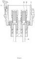
- FIG. 2 is a sectional view illustrating a structure of the inlet, taken along line II-II of FIG. 1 . As illustrated in FIGS.
- a charging inlet (inlet device) 2 for an electric vehicle may include an outer housing 10 installed on one side of the electric vehicle with an inner surface thereof exposed to the outside of the vehicle, an inlet terminal 20 installed on an inner surface of the outer housing 10 to protrude to a specific height to receive electric power, an inner housing 30 disposed in the interior of the outer housing 10 while surrounding the inlet terminal 20 to protect the inlet terminal 20 from an external impact, and a cable 40 that electrically connects the inlet terminal 20 to a high-voltage battery (not illustrated) disposed on one side of the interior of the electric vehicle.
- the outer housing 10 may be a cylindrical member, one side surface (e.g., a first side surface) of which may be opened and the interior of which may have a specific space (e.g., cavity), and a separate cover 11 that may selectively open and close an opened upper surface of the outer housing 10 may be coupled to one side of the outer surface of the outer housing 10 to be rotatable.
- a stopping member 12 that may maintain a state in which the cover member 11 shields the upper surface of the outer housing 10 may be coupled to the outer surface of the outer housing 10 on a side that is opposite to a side to which the cover member 11 is coupled to be rotatable (e.g., a second side surface), to rotate the stopping member 12.
- the inlet terminal 20 may protrude from a bottom surface of the external housing 10 to a specific height and may be connected to a charging terminal (not illustrated) provided in the charging connector 1 to receive electric power, and the inner housing 30 may be disposed on an outer surface of the inlet terminal 20.
- the inner housing 30 may be a cylindrical member, an upper surface of which may be opened such that the cylindrical member protects an external appearance of the inlet terminal 20 and connects the inlet terminal 20 to the charging terminal and the interior of which has an accommodation space in which the inlet terminal 20 may be accommodated.
- the cable 40 may electrically connect the inlet terminal 20 and the high-voltage battery disposed on one side of the interior of the electric vehicle.
- a process of charging a battery of the electric vehicle by inserting the charging connector into the inlet having the above-described structure is as follows. First, when the charging connector 1 is inserted into the outer housing 10 after the cover member 11 disposed on one side of the outer housing 10 is rotated to expose the interior of the outer housing 10 to the outside of the vehicle, the charging terminal disposed in the charging connector 1 and the inlet terminal 20 protruding from the bottom surface of the outer housing 10 may be coupled to each other. When electric power is supplied in a state in which the charging terminal and the inlet terminal 20 are coupled to each other, the electric power may be delivered to the inlet terminal 20 via the charging terminal, and the electric power may be supplied to the high-voltage battery of the electric vehicle through the cable 40 connected to the inlet terminal 20.
- the charging connector 1 may include a body part 15 in which the charging terminal connected to a power source is installed, a rotatable lever 16 disposed on one side of the body 15 to selectively supply electric power, and an outlet part 17 that protrudes from an end of the body 15 and inserted into the inlet 2 of the electric vehicle to connect the inlet terminal 20 disposed in the interior of the inlet 2 and the charging terminal.
- the body part 15 may have a curved shape such that the user inserts the charging connector 1 into the inlet 2 of the electric vehicle while gripping the member when the electric vehicle is charged, and the charging terminal connected to the power source may be installed in the interior of the body part 15.
- the rotatable lever 16 may be disposed on one side of the body part 15 to be rotatable, and electric power may be selectively supplied to the charging terminal through rotation of the rotatable lever 16. In other words, electric power may be supplied to the charging terminal when the rotatable lever 16 is attached to the body part 15, and the electric power supplied to the charging terminal may be interrupted when the rotatable lever 16 is rotated in a direction away from the body part 15.
- the outlet part 17 may be installed at an end of the body part 15 to have a diameter that is less than the diameter of the body part 15 and may protrude by a specific length, and when the electric vehicle is charged, an outer peripheral surface of the outlet part 17 may be inserted into the inlet 2 to contact the inner peripheral surface of the inlet 2 in the electric vehicle.
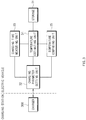
- FIG. 3 is a block diagram of an exemplary embodiment of an apparatus for preventing overheating of a charging inlet according to the present disclosure.
- the apparatus for preventing overheating of a charging inlet according to the present disclosure may include a storage 31, a charging parameter setting unit 32, a charging time measuring unit 33, a temperature estimating unit 34, and a temperature comparing unit 35.
- the various units may be operated by a controller of the vehicle.
- the storage 31 may be configured to store a map in which temperatures of the charging inlet based on charging times and charging currents for respective charging voltages are recorded.
- the temperature value of the charging inlet may be derived through experiments, and in particular, a derivation result may be classified using an interpolation method.
- the charging parameter setting unit 32 may be configured to set a charging parameter by communicating with a charger of a charging station during the charging operation.
- the charging parameter may include a charging voltage and a charging current.
- the charging parameter setting unit 32 may then be configured to reset the charging parameter to prevent the temperature of the charging inlet from exceeding a threshold temperature (e.g., about 95 ⁇ ).
- the reset parameter may be a charging current.
- the charging parameter setting unit 32 may be configured to decrease the charging current when the temperature of the charging inlet estimated by the temperature estimating unit 34 exceeds the threshold temperature according to the comparison result from the temperature comparing unit 35. For example, in response to determining that the temperature of the charging inlet exceeds the threshold temperature while a charging operation is performed at about 200 A, the charging current may be reset to less than about 200 A. Then, the charging parameter setting unit 32 may be configured to linearly decrease the charging current.
- the charging parameter setting unit 32 may be configured to return the charging current to an original value when the temperature of the charging inlet newly estimated by the temperature estimating unit 34 is decreased to a reference temperature (e.g., about 80 ⁇ ) or less after the charging current is reduced.
- the charging time measuring unit 33 may further be configured to measure a time (charging time) for which the charging operation is performed based on the charging parameter set by the charging parameter setting unit 32.
- the charging time measuring unit 33 may be a type of timer, and may be configured to count a charging time from a time at which the charging operation starts and a time at which the charging operation ends. Accordingly, the charging time measuring unit 33 may be configured to detect a lapse of the time from the start of the charging operation in unit of minutes in real time.
- the temperature estimating unit 34 may be configured to estimate the temperature of the charging inlet based on the temperature values of the charging inlet according to charging times and charging currents for respective charging voltages, which are stored in the storage 31. In other words, the temperature estimating unit 34 may be configured to detect the charging voltage and the charging current set by the charging parameter setting unit 32 and detect the charging time through the charging time measuring unit 33. Additionally, the temperature estimating unit 34 may be configured to estimate the temperature of the charging inlet based on the temperature values of the charging inlet based on charging times and charging currents for respective charging voltages, which are stored in the storage 31.
- the temperature comparing unit 35 may then be configured to compare the temperature of the charging inlet estimated by the temperature estimating unit 34 with a threshold temperature (e.g., about 95 ⁇ ) and transmit the result to the charging parameter setting unit 32. In other words, when the temperature of the charging inlet estimated by the temperature estimating unit 34 exceeds a threshold temperature (e.g., about 95 ⁇ ), the temperature comparing unit 35 may be configured to provide a notification to the charging parameter setting unit 32 regarding the charging inlet temperature.
- a threshold temperature e.g., about 95 ⁇
- the charging parameter setting unit 32 may then be configured to reset the charging parameter to prevent the temperature of the charging inlet from exceeding a threshold temperature.
- the charging parameter setting unit 32 may be configured to directly perform the function of the temperature comparing unit 35 without including the temperature comparing unit 35. The durability of the charging inlet may be improved and a fire due to overheating may be prevented in advance as well by preventing the temperature of the charging inlet from increasing excessively through the operations of the above-described elements.
- a controller in the apparatus for preventing overheating of the charging inlet may perform all the functions of the elements.
- the processor may perform all the functions of the elements based on a program for preventing overheating of the charging inlet.
- FIG. 4 is an exemplary view illustrating a change rate of the temperature of a charging inlet based on a charging time and a charging current according to the present disclosure.
- the transverse axis represents a charging time (minutes) and the longitudinal axis represents a temperature of the charging inlet. Accordingly, the temperatures of the charging inlet according to charging times for respective charging currents may be detected.
- the graph of FIG. 4 for respective charging current corresponds to a charging voltage of 400 V
- the graph of 175 A may be estimated based on a generally widely known interpolation.
- the interpolation may include a linear interpolation, an exponential interpolation, a bilinear interpolation, or a spline interpolation.
- a graph for respective charging currents when the charging voltage is 400 V graphs for respective currents according to charging voltages may be provided.
- FIG. 5 is a flowchart of an exemplary embodiment of a method for preventing overheating of a charging inlet according to the present disclosure.
- the storage 31 may be configured to store temperature values of the charging inlet based on charging times and charging currents for respective charging voltages (501).
- the temperature values of the charging inlet based on the charging times and the charging currents may be stored in the form of a table, but a plurality of table may be generated for respective charging voltages.
- the charging parameter setting unit 32 may be configured to set a charging parameter by communicating with a charger for a charging station (502). This corresponds to an initial setting process that is automatically performed when the charging connector for a charging station is connected to an inlet in the electric vehicle, and is a general technology.
- the charging time measuring unit 33 may be configured to measure a charging time (503).
- the charging time measuring unit 33 may also be a sensor.
- the temperature estimating unit 34 may be configured to estimate a temperature of the charging inlet based on the temperature values of the charging inlet according to charging times and charging currents for respective charging voltages (504). Thereafter, the temperature comparing unit 35 may be configured to compare the estimated temperature of the charging inlet with a threshold temperature (505). In other words, the temperature comparing unit 35 may be configured to determine whether the temperature of the charging inlet estimated by the temperature estimating unit 34 exceeds the threshold temperature.
- the charging parameter setting unit 32 may be configured to reset the charging parameter to prevent the temperature of the charging inlet from exceeding a threshold temperature (506).
- the charging parameter setting unit 32 may be configured to decrease the temperature of the charging inlet by decreasing the charging current when the temperature of the charging inlet exceeds the threshold temperature (e.g., about 95 ⁇ ).
- the charging parameter setting unit 32 may be configured to return the charging current to an original value when the temperature of the charging inlet is decreased to a reference temperature (e.g., about 80 ⁇ ) or less, after decreasing the charging current.
- FIG. 6 is a view illustrating a method for realizing a controller of the apparatus for preventing overheating of a charging inlet according to the present disclosure.
- the controller of the apparatus for preventing overheating of a charging inlet according to the present disclosure may include hardware, software, and a combination thereof.
- the controller may be realized by a computing system 1000 of FIG. 6 .
- the computing system 1000 may include at least one processor 1100 connected via a bus 1200, a memory 1300, a user interface input device 1400, a user interface output device 1500, a storage 1600, and a network interface 1700.
- the processor 1100 may be a central processing unit (CPU) or a semiconductor device configured to execute instructions stored in the memory 1300 and/or the storage 1600.
- the memory 1300 and the storage 1600 may include various volatile or nonvolatile storage media.
- the memory 1300 may include a read only memory (ROM) and a random access memory (RAM).
- the steps of the method or algorithm described in relation to the exemplary embodiments of the present disclosure may be implemented directly by hardware executed by the processor 1100, a software module, or a combination thereof.
- the software module may reside in a storage medium (that is, the memory 1300 and/or the storage 1600), such as a RAM memory, a flash memory, a ROM memory, an EPROM memory, an EEPROM memory, a register, a hard disk, a detachable disk, or a CD-ROM.
- the exemplary storage medium may be coupled to the processor 1100, and the processor 1100 may read information from the storage medium and may write information in the storage medium.
- the storage medium may be integrated with the processor 1100.
- the processor and the storage medium may reside in an application specific integrated circuit (ASIC).
- the ASIC may reside in a user terminal.
- the processor and the storage medium may reside in the user terminal as an individual component.
- the durability of a charging inlet may be improved by estimating the temperature of the charging inlet based on a charging voltage, a charging current, and a charging time of the electric vehicle and resetting the charging current such that the estimated temperature of the charging inlet does not exceed a threshold temperature. Additionally, a fire due to overheating may be prevented in advance by estimating the temperature of the charging inlet based on a charging voltage, a charging current, and a charging time of the electric vehicle and resetting the charging current to prevent the estimated temperature of the charging inlet from exceeding a threshold temperature.
- the temperature of the charging inlet may be estimated based on a charging voltage, a charging current, and a charging time of the electric vehicle, a temperature sensor is not necessary. Additionally, according to the present disclosure, since a temperature sensor is not necessary, a measure for a breakdown of a temperature sensor is not necessary. Lastly, a stability of the electric vehicle may be secured for consumers by improving the durability of the charging inlet and preventing a fire of the electric vehicle in advance.
Landscapes
- Engineering & Computer Science (AREA)
- Power Engineering (AREA)
- Mechanical Engineering (AREA)
- Transportation (AREA)
- Sustainable Development (AREA)
- Life Sciences & Earth Sciences (AREA)
- Sustainable Energy (AREA)
- Microelectronics & Electronic Packaging (AREA)
- Charge And Discharge Circuits For Batteries Or The Like (AREA)
- Electric Propulsion And Braking For Vehicles (AREA)
- Crystals, And After-Treatments Of Crystals (AREA)
- Gasification And Melting Of Waste (AREA)
- Mechanical Treatment Of Semiconductor (AREA)
Claims (7)
- Vorrichtung zum Verhindern einer Überhitzung eines Ladeeinlasses (2), umfassend:einen Speicher (1300), der eingerichtet ist, um Programmanweisungen zu speichern; undeinen Prozessor (1100), der eingerichtet ist, um die Programmanweisungen auszuführen, wobei die Programmanweisungen, wenn sie ausgeführt werden,eingerichtet sind zum:Messen einer Ladezeit;Schätzen einer Temperatur des Ladeeinlasses (2) unter Verwendung einer Abbildung, in der die Temperatur des Ladeeinlasses (2) basierend auf Ladezeiten und Ladeströmen für jeweilige Ladespannungen aufgezeichnet sind; undFestlegen einer Ladespannung und eines Ladestroms durch Kommunikation mit einer Ladeeinrichtung und Verringern des Ladestroms, um zu verhindern, dass die Temperatur des Ladeeinlasses (2) eine Schwellentemperatur überschreitet.
- Vorrichtung nach Anspruch 1, wobei der Ladestrom auf einen ursprünglichen Wert zurückgeführt wird, wenn die Temperatur des Ladeeinlasses (2) auf eine Referenztemperatur oder weniger verringert wird, nachdem der Ladestrom reduziert wurde.
- Vorrichtung nach Anspruch 1, wobei die Programmanweisungen, wenn sie ausgeführt werden, ferner eingerichtet sind, um die geschätzte Temperatur des Ladeeinlasses (2) mit einer Schwellentemperatur zu vergleichen.
- Vorrichtung nach Anspruch 3, wobei die Programmanweisungen, wenn sie ausgeführt werden, ferner eingerichtet sind, um zu bestimmen, ob die geschätzte Temperatur des Ladeeinlasses (2) die Schwellentemperatur überschreitet.
- Verfahren zum Verhindern einer Überhitzung eines Ladeeinlasses (2), umfassend:Festlegen, durch eine Steuerung, einer Ladespannung undeines Ladestroms durch Kommunikation mit einer Ladeeinrichtung;Messen, durch die Steuerung, einer Ladezeit;Schätzen, durch die Steuerung, einer Temperatur des Ladeeinlasses (2) unter Verwendung einer Abbildung, in der die Temperatur des Ladeeinlasses (2) basierend auf Ladezeiten und Ladeströmen für jeweilige Ladespannungen aufgezeichnet sind; undVerringern, durch die Steuerung, des Ladestroms, um zu verhindern, dass die Temperatur des Ladeeinlasses (2) eine Schwellentemperatur überschreitet.
- Verfahren nach Anspruch 5, wobei das Verringern des Ladestroms umfasst:
Zurückführen, durch die Steuerung, des Ladestroms auf einen ursprünglichen Wert, wenn die Temperatur des Ladeeinlasses auf eine Referenztemperatur oder weniger verringert wird, nachdem der Ladestrom reduziert wurde. - Verfahren nach Anspruch 5, ferner umfassend:
Bestimmen, durch die Steuerung, ob die geschätzte Temperatur des Ladeeinlasses eine Schwellentemperatur überschreitet.
Applications Claiming Priority (1)
| Application Number | Priority Date | Filing Date | Title |
|---|---|---|---|
| KR1020170134081A KR102441070B1 (ko) | 2017-10-16 | 2017-10-16 | 충전용 인렛의 과온 방지 장치 및 그 방법 |
Publications (2)
| Publication Number | Publication Date |
|---|---|
| EP3470254A1 EP3470254A1 (de) | 2019-04-17 |
| EP3470254B1 true EP3470254B1 (de) | 2021-01-06 |
Family
ID=60515163
Family Applications (1)
| Application Number | Title | Priority Date | Filing Date |
|---|---|---|---|
| EP17204129.5A Active EP3470254B1 (de) | 2017-10-16 | 2017-11-28 | Vorrichtung und verfahren zur verhinderung einer überhitzung eines ladelufteinlasses |
Country Status (4)
| Country | Link |
|---|---|
| US (1) | US10486535B2 (de) |
| EP (1) | EP3470254B1 (de) |
| KR (1) | KR102441070B1 (de) |
| CN (1) | CN110014928B (de) |
Cited By (1)
| Publication number | Priority date | Publication date | Assignee | Title |
|---|---|---|---|---|
| EP4105270A1 (de) | 2021-06-15 | 2022-12-21 | LANXESS Deutschland GmbH | Polyamidzusammensetzungen |
Families Citing this family (6)
| Publication number | Priority date | Publication date | Assignee | Title |
|---|---|---|---|---|
| CN110884375B (zh) * | 2019-12-03 | 2020-12-22 | 福建百城新能源科技有限公司 | 一种用于储充系统的智能应急安全保护系统及方法 |
| KR102869083B1 (ko) * | 2019-12-10 | 2025-10-13 | 현대자동차주식회사 | 배터리 충전 제어 장치 및 방법 |
| CN113885610A (zh) * | 2021-12-06 | 2022-01-04 | 南京芯圣电子科技有限公司 | 一种温度控制系统、方法、装置、设备及可读存储介质 |
| CN116409152B (zh) * | 2021-12-30 | 2024-10-29 | 比亚迪股份有限公司 | 充电装置的过温保护方法和装置、电动车辆 |
| CN115092001B (zh) * | 2022-04-28 | 2023-08-04 | 芜湖宏景电子股份有限公司 | 电动汽车充电组件温度监控系统 |
| JP2025054142A (ja) * | 2023-09-26 | 2025-04-07 | トヨタ自動車株式会社 | 充電制御装置 |
Family Cites Families (16)
| Publication number | Priority date | Publication date | Assignee | Title |
|---|---|---|---|---|
| JP4162026B2 (ja) * | 2006-09-29 | 2008-10-08 | トヨタ自動車株式会社 | 車両充電システム、車両充電装置および電動車両 |
| WO2010049775A2 (en) * | 2008-10-28 | 2010-05-06 | Panasonic Electric Works Co., Ltd. | Charging cable, charging cable unit, and charging system for electric vehicle |
| JP5031020B2 (ja) * | 2009-12-28 | 2012-09-19 | 本田技研工業株式会社 | 充電カプラおよび充電制御装置 |
| KR101154673B1 (ko) * | 2010-11-08 | 2012-06-08 | 기아자동차주식회사 | 배터리의 온도 추정 로직 및 방법 |
| EP2613420B1 (de) * | 2010-11-25 | 2019-03-06 | Honda Motor Co., Ltd. | Ladesteuerungsvorrichtung für elektrofahrzeuge |
| JP5934905B2 (ja) * | 2011-03-03 | 2016-06-15 | パナソニックIpマネジメント株式会社 | 電気推進車両用充電ケーブル |
| US9515498B2 (en) * | 2012-03-08 | 2016-12-06 | Panasonic Intellectual Property Management Co., Ltd. | Charging cable |
| KR20130136290A (ko) | 2012-06-04 | 2013-12-12 | 주식회사 유라코퍼레이션 | 전기자동차 충전용 아웃렛 커넥터와 인렛 커넥터 및 이를 이용한 전기자동차 충전방법 |
| KR20140003082A (ko) * | 2012-06-29 | 2014-01-09 | 엘에스산전 주식회사 | 전기 자동차용 충전기 |
| EP2865558B1 (de) * | 2013-10-24 | 2016-12-28 | Volvo Car Corporation | Verfahren und System zur Ladesteuerung einer Energiespeichervorrichtung |
| US9490640B2 (en) * | 2013-12-18 | 2016-11-08 | Ford Global Technologies, Llc | Temperature monitoring HEV charger cord assembly and charging method |
| KR20160031809A (ko) * | 2014-09-15 | 2016-03-23 | 엘에스산전 주식회사 | 전기 자동차 충전 장치 |
| DE102014016825B4 (de) * | 2014-11-13 | 2023-06-29 | Audi Ag | Kraftfahrzeug-Ladedose mit Überhitzungsschutz |
| CN205081514U (zh) * | 2015-10-28 | 2016-03-09 | 无锡中感微电子股份有限公司 | 充电装置 |
| WO2017138939A1 (en) * | 2016-02-11 | 2017-08-17 | Lear Corporation | Vehicle charge-cord system |
| US20170334300A1 (en) * | 2016-05-20 | 2017-11-23 | Faraday&Future Inc. | Charging System with Temperature Sensor |
-
2017
- 2017-10-16 KR KR1020170134081A patent/KR102441070B1/ko active Active
- 2017-11-28 EP EP17204129.5A patent/EP3470254B1/de active Active
- 2017-12-01 CN CN201711249636.XA patent/CN110014928B/zh active Active
- 2017-12-05 US US15/831,978 patent/US10486535B2/en active Active
Non-Patent Citations (1)
| Title |
|---|
| None * |
Cited By (2)
| Publication number | Priority date | Publication date | Assignee | Title |
|---|---|---|---|---|
| EP4105270A1 (de) | 2021-06-15 | 2022-12-21 | LANXESS Deutschland GmbH | Polyamidzusammensetzungen |
| EP4105271A1 (de) | 2021-06-15 | 2022-12-21 | LANXESS Performance Materials GmbH | Polyamidzusammensetzungen |
Also Published As
| Publication number | Publication date |
|---|---|
| US10486535B2 (en) | 2019-11-26 |
| KR102441070B1 (ko) | 2022-09-06 |
| CN110014928A (zh) | 2019-07-16 |
| EP3470254A1 (de) | 2019-04-17 |
| KR20190042314A (ko) | 2019-04-24 |
| US20190111796A1 (en) | 2019-04-18 |
| CN110014928B (zh) | 2023-02-28 |
Similar Documents
| Publication | Publication Date | Title |
|---|---|---|
| EP3470254B1 (de) | Vorrichtung und verfahren zur verhinderung einer überhitzung eines ladelufteinlasses | |
| EP3252489B1 (de) | Vorrichtung und verfahren zur bestimmung des batteriezustandes | |
| US10059222B2 (en) | Battery temperature estimation system | |
| US12528374B2 (en) | Apparatus for controlling charging or discharging of vehicle, system for supplying power to outside of the vehicle, and method thereof | |
| US9283861B2 (en) | On-board battery charger for electric vehicles and control method thereof | |
| US20160084917A1 (en) | Apparatus and method for diagnosing degradation of a high voltage battery of a vehicle | |
| US20170136913A1 (en) | Apparatus and method for detecting relay fusion of eco-friendly vehicle | |
| US11075516B2 (en) | Relay temperature measuring device for battery and method | |
| US9977082B2 (en) | System and method for detecting fusion of relay of a battery when engaging or disengaging the ignition of vehicle | |
| US20170028948A1 (en) | Battery management system for vehicle and controlling method thereof | |
| US20180297474A1 (en) | System and method of maintaining high voltage battery charging with detected auxiliary battery fault | |
| US9783060B2 (en) | Traction battery leakage detection system for electrified vehicle | |
| US9632118B2 (en) | Current sensing device and method using current transformer | |
| US10081247B2 (en) | System, method and apparatus for protecting OBC output terminal | |
| CN118613986A (zh) | 快速充电控制装置和方法 | |
| CN110871696A (zh) | 充电控制装置 | |
| US20170115370A1 (en) | Apparatus and method of diagnosing current sensor of eco-friendly vehicle | |
| US20200110136A1 (en) | Vehicle battery diagnosis method and apparatus | |
| US12308582B2 (en) | Charging control box detachable charging cable system | |
| US9527397B2 (en) | Apparatus and method for preventing overshoot at the beginning of slow charging | |
| US10923935B2 (en) | Charging apparatus, a vehicle including same, and a method for controlling a charging apparatus | |
| CN111605435A (zh) | 蓄电池装置 | |
| US20160046279A1 (en) | Forced charging method for phev vehicles using motor and hsg | |
| US11745623B2 (en) | Vehicle and control method of adjusting preheating temperature of battery | |
| US12103427B2 (en) | Method for determining the support of energy content and power of a battery |
Legal Events
| Date | Code | Title | Description |
|---|---|---|---|
| PUAI | Public reference made under article 153(3) epc to a published international application that has entered the european phase |
Free format text: ORIGINAL CODE: 0009012 |
|
| STAA | Information on the status of an ep patent application or granted ep patent |
Free format text: STATUS: THE APPLICATION HAS BEEN PUBLISHED |
|
| AK | Designated contracting states |
Kind code of ref document: A1 Designated state(s): AL AT BE BG CH CY CZ DE DK EE ES FI FR GB GR HR HU IE IS IT LI LT LU LV MC MK MT NL NO PL PT RO RS SE SI SK SM TR |
|
| AX | Request for extension of the european patent |
Extension state: BA ME |
|
| STAA | Information on the status of an ep patent application or granted ep patent |
Free format text: STATUS: REQUEST FOR EXAMINATION WAS MADE |
|
| 17P | Request for examination filed |
Effective date: 20191008 |
|
| RBV | Designated contracting states (corrected) |
Designated state(s): AL AT BE BG CH CY CZ DE DK EE ES FI FR GB GR HR HU IE IS IT LI LT LU LV MC MK MT NL NO PL PT RO RS SE SI SK SM TR |
|
| RIC1 | Information provided on ipc code assigned before grant |
Ipc: B60L 3/04 20060101AFI20200214BHEP Ipc: H01R 13/00 20060101ALI20200214BHEP Ipc: B60L 53/60 20190101ALI20200214BHEP Ipc: B60L 53/16 20190101ALI20200214BHEP |
|
| GRAP | Despatch of communication of intention to grant a patent |
Free format text: ORIGINAL CODE: EPIDOSNIGR1 |
|
| STAA | Information on the status of an ep patent application or granted ep patent |
Free format text: STATUS: GRANT OF PATENT IS INTENDED |
|
| INTG | Intention to grant announced |
Effective date: 20200728 |
|
| GRAS | Grant fee paid |
Free format text: ORIGINAL CODE: EPIDOSNIGR3 |
|
| GRAA | (expected) grant |
Free format text: ORIGINAL CODE: 0009210 |
|
| STAA | Information on the status of an ep patent application or granted ep patent |
Free format text: STATUS: THE PATENT HAS BEEN GRANTED |
|
| AK | Designated contracting states |
Kind code of ref document: B1 Designated state(s): AL AT BE BG CH CY CZ DE DK EE ES FI FR GB GR HR HU IE IS IT LI LT LU LV MC MK MT NL NO PL PT RO RS SE SI SK SM TR |
|
| REG | Reference to a national code |
Ref country code: GB Ref legal event code: FG4D |
|
| REG | Reference to a national code |
Ref country code: AT Ref legal event code: REF Ref document number: 1351983 Country of ref document: AT Kind code of ref document: T Effective date: 20210115 Ref country code: CH Ref legal event code: EP |
|
| REG | Reference to a national code |
Ref country code: DE Ref legal event code: R096 Ref document number: 602017030850 Country of ref document: DE |
|
| REG | Reference to a national code |
Ref country code: IE Ref legal event code: FG4D |
|
| REG | Reference to a national code |
Ref country code: NL Ref legal event code: MP Effective date: 20210106 |
|
| REG | Reference to a national code |
Ref country code: AT Ref legal event code: MK05 Ref document number: 1351983 Country of ref document: AT Kind code of ref document: T Effective date: 20210106 |
|
| REG | Reference to a national code |
Ref country code: LT Ref legal event code: MG9D |
|
| PG25 | Lapsed in a contracting state [announced via postgrant information from national office to epo] |
Ref country code: GR Free format text: LAPSE BECAUSE OF FAILURE TO SUBMIT A TRANSLATION OF THE DESCRIPTION OR TO PAY THE FEE WITHIN THE PRESCRIBED TIME-LIMIT Effective date: 20210407 Ref country code: HR Free format text: LAPSE BECAUSE OF FAILURE TO SUBMIT A TRANSLATION OF THE DESCRIPTION OR TO PAY THE FEE WITHIN THE PRESCRIBED TIME-LIMIT Effective date: 20210106 Ref country code: FI Free format text: LAPSE BECAUSE OF FAILURE TO SUBMIT A TRANSLATION OF THE DESCRIPTION OR TO PAY THE FEE WITHIN THE PRESCRIBED TIME-LIMIT Effective date: 20210106 Ref country code: NO Free format text: LAPSE BECAUSE OF FAILURE TO SUBMIT A TRANSLATION OF THE DESCRIPTION OR TO PAY THE FEE WITHIN THE PRESCRIBED TIME-LIMIT Effective date: 20210406 Ref country code: PT Free format text: LAPSE BECAUSE OF FAILURE TO SUBMIT A TRANSLATION OF THE DESCRIPTION OR TO PAY THE FEE WITHIN THE PRESCRIBED TIME-LIMIT Effective date: 20210506 Ref country code: BG Free format text: LAPSE BECAUSE OF FAILURE TO SUBMIT A TRANSLATION OF THE DESCRIPTION OR TO PAY THE FEE WITHIN THE PRESCRIBED TIME-LIMIT Effective date: 20210406 Ref country code: LT Free format text: LAPSE BECAUSE OF FAILURE TO SUBMIT A TRANSLATION OF THE DESCRIPTION OR TO PAY THE FEE WITHIN THE PRESCRIBED TIME-LIMIT Effective date: 20210106 |
|
| PG25 | Lapsed in a contracting state [announced via postgrant information from national office to epo] |
Ref country code: SE Free format text: LAPSE BECAUSE OF FAILURE TO SUBMIT A TRANSLATION OF THE DESCRIPTION OR TO PAY THE FEE WITHIN THE PRESCRIBED TIME-LIMIT Effective date: 20210106 Ref country code: PL Free format text: LAPSE BECAUSE OF FAILURE TO SUBMIT A TRANSLATION OF THE DESCRIPTION OR TO PAY THE FEE WITHIN THE PRESCRIBED TIME-LIMIT Effective date: 20210106 Ref country code: LV Free format text: LAPSE BECAUSE OF FAILURE TO SUBMIT A TRANSLATION OF THE DESCRIPTION OR TO PAY THE FEE WITHIN THE PRESCRIBED TIME-LIMIT Effective date: 20210106 Ref country code: RS Free format text: LAPSE BECAUSE OF FAILURE TO SUBMIT A TRANSLATION OF THE DESCRIPTION OR TO PAY THE FEE WITHIN THE PRESCRIBED TIME-LIMIT Effective date: 20210106 Ref country code: AT Free format text: LAPSE BECAUSE OF FAILURE TO SUBMIT A TRANSLATION OF THE DESCRIPTION OR TO PAY THE FEE WITHIN THE PRESCRIBED TIME-LIMIT Effective date: 20210106 |
|
| PG25 | Lapsed in a contracting state [announced via postgrant information from national office to epo] |
Ref country code: IS Free format text: LAPSE BECAUSE OF FAILURE TO SUBMIT A TRANSLATION OF THE DESCRIPTION OR TO PAY THE FEE WITHIN THE PRESCRIBED TIME-LIMIT Effective date: 20210506 |
|
| REG | Reference to a national code |
Ref country code: DE Ref legal event code: R097 Ref document number: 602017030850 Country of ref document: DE |
|
| PG25 | Lapsed in a contracting state [announced via postgrant information from national office to epo] |
Ref country code: EE Free format text: LAPSE BECAUSE OF FAILURE TO SUBMIT A TRANSLATION OF THE DESCRIPTION OR TO PAY THE FEE WITHIN THE PRESCRIBED TIME-LIMIT Effective date: 20210106 Ref country code: CZ Free format text: LAPSE BECAUSE OF FAILURE TO SUBMIT A TRANSLATION OF THE DESCRIPTION OR TO PAY THE FEE WITHIN THE PRESCRIBED TIME-LIMIT Effective date: 20210106 Ref country code: SM Free format text: LAPSE BECAUSE OF FAILURE TO SUBMIT A TRANSLATION OF THE DESCRIPTION OR TO PAY THE FEE WITHIN THE PRESCRIBED TIME-LIMIT Effective date: 20210106 |
|
| PLBE | No opposition filed within time limit |
Free format text: ORIGINAL CODE: 0009261 |
|
| STAA | Information on the status of an ep patent application or granted ep patent |
Free format text: STATUS: NO OPPOSITION FILED WITHIN TIME LIMIT |
|
| PG25 | Lapsed in a contracting state [announced via postgrant information from national office to epo] |
Ref country code: DK Free format text: LAPSE BECAUSE OF FAILURE TO SUBMIT A TRANSLATION OF THE DESCRIPTION OR TO PAY THE FEE WITHIN THE PRESCRIBED TIME-LIMIT Effective date: 20210106 Ref country code: RO Free format text: LAPSE BECAUSE OF FAILURE TO SUBMIT A TRANSLATION OF THE DESCRIPTION OR TO PAY THE FEE WITHIN THE PRESCRIBED TIME-LIMIT Effective date: 20210106 Ref country code: SK Free format text: LAPSE BECAUSE OF FAILURE TO SUBMIT A TRANSLATION OF THE DESCRIPTION OR TO PAY THE FEE WITHIN THE PRESCRIBED TIME-LIMIT Effective date: 20210106 |
|
| 26N | No opposition filed |
Effective date: 20211007 |
|
| PG25 | Lapsed in a contracting state [announced via postgrant information from national office to epo] |
Ref country code: AL Free format text: LAPSE BECAUSE OF FAILURE TO SUBMIT A TRANSLATION OF THE DESCRIPTION OR TO PAY THE FEE WITHIN THE PRESCRIBED TIME-LIMIT Effective date: 20210106 Ref country code: ES Free format text: LAPSE BECAUSE OF FAILURE TO SUBMIT A TRANSLATION OF THE DESCRIPTION OR TO PAY THE FEE WITHIN THE PRESCRIBED TIME-LIMIT Effective date: 20210106 |
|
| PG25 | Lapsed in a contracting state [announced via postgrant information from national office to epo] |
Ref country code: SI Free format text: LAPSE BECAUSE OF FAILURE TO SUBMIT A TRANSLATION OF THE DESCRIPTION OR TO PAY THE FEE WITHIN THE PRESCRIBED TIME-LIMIT Effective date: 20210106 |
|
| PG25 | Lapsed in a contracting state [announced via postgrant information from national office to epo] |
Ref country code: IT Free format text: LAPSE BECAUSE OF FAILURE TO SUBMIT A TRANSLATION OF THE DESCRIPTION OR TO PAY THE FEE WITHIN THE PRESCRIBED TIME-LIMIT Effective date: 20210106 |
|
| PG25 | Lapsed in a contracting state [announced via postgrant information from national office to epo] |
Ref country code: IS Free format text: LAPSE BECAUSE OF FAILURE TO SUBMIT A TRANSLATION OF THE DESCRIPTION OR TO PAY THE FEE WITHIN THE PRESCRIBED TIME-LIMIT Effective date: 20210506 |
|
| PG25 | Lapsed in a contracting state [announced via postgrant information from national office to epo] |
Ref country code: MC Free format text: LAPSE BECAUSE OF FAILURE TO SUBMIT A TRANSLATION OF THE DESCRIPTION OR TO PAY THE FEE WITHIN THE PRESCRIBED TIME-LIMIT Effective date: 20210106 |
|
| REG | Reference to a national code |
Ref country code: CH Ref legal event code: PL |
|
| PG25 | Lapsed in a contracting state [announced via postgrant information from national office to epo] |
Ref country code: LU Free format text: LAPSE BECAUSE OF NON-PAYMENT OF DUE FEES Effective date: 20211128 Ref country code: BE Free format text: LAPSE BECAUSE OF NON-PAYMENT OF DUE FEES Effective date: 20211130 |
|
| REG | Reference to a national code |
Ref country code: BE Ref legal event code: MM Effective date: 20211130 |
|
| PG25 | Lapsed in a contracting state [announced via postgrant information from national office to epo] |
Ref country code: LI Free format text: LAPSE BECAUSE OF NON-PAYMENT OF DUE FEES Effective date: 20211130 Ref country code: CH Free format text: LAPSE BECAUSE OF NON-PAYMENT OF DUE FEES Effective date: 20211130 |
|
| PG25 | Lapsed in a contracting state [announced via postgrant information from national office to epo] |
Ref country code: IE Free format text: LAPSE BECAUSE OF NON-PAYMENT OF DUE FEES Effective date: 20211128 |
|
| P01 | Opt-out of the competence of the unified patent court (upc) registered |
Effective date: 20230420 |
|
| PG25 | Lapsed in a contracting state [announced via postgrant information from national office to epo] |
Ref country code: NL Free format text: LAPSE BECAUSE OF NON-PAYMENT OF DUE FEES Effective date: 20210206 Ref country code: CY Free format text: LAPSE BECAUSE OF FAILURE TO SUBMIT A TRANSLATION OF THE DESCRIPTION OR TO PAY THE FEE WITHIN THE PRESCRIBED TIME-LIMIT Effective date: 20210106 |
|
| PG25 | Lapsed in a contracting state [announced via postgrant information from national office to epo] |
Ref country code: HU Free format text: LAPSE BECAUSE OF FAILURE TO SUBMIT A TRANSLATION OF THE DESCRIPTION OR TO PAY THE FEE WITHIN THE PRESCRIBED TIME-LIMIT; INVALID AB INITIO Effective date: 20171128 |
|
| PG25 | Lapsed in a contracting state [announced via postgrant information from national office to epo] |
Ref country code: MK Free format text: LAPSE BECAUSE OF FAILURE TO SUBMIT A TRANSLATION OF THE DESCRIPTION OR TO PAY THE FEE WITHIN THE PRESCRIBED TIME-LIMIT Effective date: 20210106 |
|
| PG25 | Lapsed in a contracting state [announced via postgrant information from national office to epo] |
Ref country code: MT Free format text: LAPSE BECAUSE OF FAILURE TO SUBMIT A TRANSLATION OF THE DESCRIPTION OR TO PAY THE FEE WITHIN THE PRESCRIBED TIME-LIMIT Effective date: 20210106 |
|
| PGFP | Annual fee paid to national office [announced via postgrant information from national office to epo] |
Ref country code: GB Payment date: 20241021 Year of fee payment: 8 |
|
| PGFP | Annual fee paid to national office [announced via postgrant information from national office to epo] |
Ref country code: FR Payment date: 20241022 Year of fee payment: 8 |
|
| PG25 | Lapsed in a contracting state [announced via postgrant information from national office to epo] |
Ref country code: TR Free format text: LAPSE BECAUSE OF FAILURE TO SUBMIT A TRANSLATION OF THE DESCRIPTION OR TO PAY THE FEE WITHIN THE PRESCRIBED TIME-LIMIT Effective date: 20210106 |
|
| PGFP | Annual fee paid to national office [announced via postgrant information from national office to epo] |
Ref country code: DE Payment date: 20251020 Year of fee payment: 9 |