EP3470295B1 - Mécanisme de désaccouplement automatique pour un attelage de véhicule - Google Patents
Mécanisme de désaccouplement automatique pour un attelage de véhicule Download PDFInfo
- Publication number
- EP3470295B1 EP3470295B1 EP17836441.0A EP17836441A EP3470295B1 EP 3470295 B1 EP3470295 B1 EP 3470295B1 EP 17836441 A EP17836441 A EP 17836441A EP 3470295 B1 EP3470295 B1 EP 3470295B1
- Authority
- EP
- European Patent Office
- Prior art keywords
- coupler
- rotating member
- coupler knuckle
- knuckle spindle
- boss
- Prior art date
- Legal status (The legal status is an assumption and is not a legal conclusion. Google has not performed a legal analysis and makes no representation as to the accuracy of the status listed.)
- Active
Links
Images


Classifications
-
- B—PERFORMING OPERATIONS; TRANSPORTING
- B61—RAILWAYS
- B61G—COUPLINGS; DRAUGHT AND BUFFING APPLIANCES
- B61G3/00—Couplings comprising mating parts of similar shape or form which can be coupled without the use of any additional element or elements
- B61G3/10—Couplings comprising mating parts of similar shape or form which can be coupled without the use of any additional element or elements with coupling heads in the form of hook-like interengaging rigid jaws, e.g. "Willison" type
- B61G3/14—Control devices, e.g. for uncoupling
-
- B—PERFORMING OPERATIONS; TRANSPORTING
- B61—RAILWAYS
- B61G—COUPLINGS; DRAUGHT AND BUFFING APPLIANCES
- B61G7/00—Details or accessories
-
- B—PERFORMING OPERATIONS; TRANSPORTING
- B61—RAILWAYS
- B61G—COUPLINGS; DRAUGHT AND BUFFING APPLIANCES
- B61G3/00—Couplings comprising mating parts of similar shape or form which can be coupled without the use of any additional element or elements
- B61G3/16—Couplings comprising mating parts of similar shape or form which can be coupled without the use of any additional element or elements with coupling heads rigidly connected by rotatable hook plates or discs and balancing links, the coupling members forming a parallelogram, e.g. "Scharfenberg" type
- B61G3/20—Control devices, e.g. for uncoupling
-
- B—PERFORMING OPERATIONS; TRANSPORTING
- B61—RAILWAYS
- B61G—COUPLINGS; DRAUGHT AND BUFFING APPLIANCES
- B61G7/00—Details or accessories
- B61G7/02—Hand tools for coupling or uncoupling
Definitions
- the present application belongs to the technical field of coupling devices for train couplers and particularly relates to an automatic uncoupling mechanism for couplers.
- an uncoupling device functions to push a coupler knuckle mechanism to rotate so as to uncouple couplers.
- Prior uncoupling methods include manual uncoupling and automatic uncoupling, wherein the prior automatic uncoupling method for railway vehicles in China is pneumatic uncoupling.
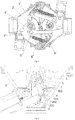
- a conventional uncoupling device is shown in Fig. 1 .
- Two uncoupling mechanisms are shown in Fig. 1 . Since the two uncoupling mechanisms are the same in structure, only one of them will be described.
- the conventional uncoupling device includes a coupler body 1' in which a coupler knuckle spindle 2' is provided.
- the coupler knuckle spindle 2' passes through a coupler knuckle 3' and is able to push the coupler knuckle 3' to rotate.
- the coupler knuckle 3' is connected to a coupling rod 4'.
- the connection between the coupler knuckle 3' and the coupling rod 4' may be realized by a pin 5'.
- the uncoupling device further includes a tension spring 6'. One end of the tension spring 6' is connected to the coupling rod 4', while the other end thereof is connected to the coupler body 1'.
- a cylinder piston rod 7' is further provided on the coupler body 1' to provide power for pushing the coupler knuckle 3' to move.
- the Chinese Utility Model CN200981560Y discloses a compact tight-lock coupler, wherein an uncoupling cylinder is disposed in an inner cavity of a coupler body, and one end of the uncoupling cylinder is hinged to an uncoupling crank while the other end thereof is mounted on an inner wall of the coupler body.
- uncoupling uncoupling cylinders of two couplers are inflated, and piston push rods drive uncoupling cranks to push two coupler knuckles to rotate until the two couplers may be uncoupled from each other.
- the coupler knuckles return to the to-be-coupled positions due to the tension of tension springs.
- the uncoupling device provides a technical means for hinging a cylinder piston rod to a coupler knuckle mechanism, so that the technical problems of the large lateral force applied to the cylinder piston and the damage to the paint on the coupler knuckle caused by the cylinder piston rod are solved during uncoupling.
- this uncoupling device still has the following technical problems.
- coupler knuckles of two couplers are pushed to rotate by thrust forces from two trains. After the couplers are rotated to a maximum angle, due to the resistance from the cylinder rod, the coupler knuckles are difficult to quickly rotate and lock the two couplers under the tension of the tension springs.
- the Chinese Utility Model CN201136515Y discloses a link-type automatic uncoupling device for tight-lock couplers, wherein a central shaft is disposed in an inner cavity of a coupler knuckle, a spindle is fixedly mounted on the central shaft, an uncoupling crank is hinged to the spindle by a connecting rod, and a cylinder piston of an uncoupling cylinder is positioned at the tail of the spindle.
- the uncoupling device further provides a spring sheathed on the cylinder piston.
- GB1314438A discloses automatic central buffer couplings, for rail vehicle, of the type comprising a lock bolt adapted to be moved from a locking position to a release position to enable the buffer coupling to be uncoupled from a similar coupling.
- the present application provides a novel automatic uncoupling mechanism for couplers.
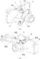
- an automatic uncoupling mechanism for couplers including a coupler knuckle spindle 1 and a driving unit 2.
- the driving unit 2 includes a cylinder body 201 hinged to a coupler body 3 and a telescopic member 202 capable of moving in an axial direction of the cylinder body 201.
- the automatic uncoupling mechanism for couplers further includes a first rotating member 4, a boss 5 and a boss stopper 6, wherein the first rotating member 4 includes a crank 401 hinged to the telescopic member 202 and a rotating part 402 fixedly connected to the crank 401.
- the rotating part 402 is sheathed on the coupler knuckle spindle 1.
- the driving unit 2 unidirectionally drives the telescopic member 202 so that the rotating part 402 drives the coupler knuckle spindle 1 to unidirectionally rotate by a contact between the boss 5 and the boss stopper 6, so as to realize coupler uncoupling.
- the rotation of the coupler knuckle spindle 1 for achieving coupler coupling is not limited by the rotating part 402.
- the hinged connection may be a direct hinged connection between components, or may be an indirect hinged connection.
- the hinged connection between the driving unit 2 and the coupler body 3 may be a hinged connection between a support plate located under the driving unit 2 with the coupler body 3, so that the hinged connection between the driving unit 2 and the coupler body 3 is an indirect hinged connection; and the direct hinged connection between the telescopic member 202 and the crank 401 may be realized by a pin, a fixation member or other conventional components.
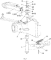
- the automatic uncoupling mechanism for couplers further includes a second rotating member 7 for limiting the movement of the rotating part 402 in the axis direction of the coupler knuckle spindle 1, and the second rotating member 7 is fixedly connected to the coupler knuckle spindle 1.
- the second rotating member 7 is located above the rotating part 402.
- the coupler knuckle spindle 1 is enabled to simultaneously rotate with the first rotating member 4 during the coupler uncoupling process but independently rotate during the coupler coupling process. Consequently, it is ensured that the tension spring drives the coupler knuckle to quickly rotate and lock the couplers, and it is advantageous for smooth coupler coupling under the premise of ensuring high efficiency of the automatic uncoupling approach.
- the boss 5 is fixedly mounted above the rotating part 402.
- the second rotating member 7 is located above the rotating part 402 and may be a cover plate structure. Left and right portions of the second rotating member 7 come into close contact with the rotating part 402 (as shown in Figs. 3 and 4 ), that is, the second rotating member 7 may cover the rotating part 402 to avoid the movement of the rotating part in the axial direction.
- the position of the boss 5 corresponds to that of the second rotating member 7.
- the second rotating member 7 may be fixed on the coupler knuckle spindle 1 by two or more screws 8.
- a groove 10 is formed on the second rotating member 7, and the boss stopper 6 is a radial sidewall of the groove 10, i.e., an upper sidewall 11 shown in Fig. 2 .
- a coupler knuckle spindle 1(2') and a coupler knuckle 12(3') are included in the coupler body 3(1'); the coupler knuckle spindle 1(2') passes through the coupler knuckle 12(3'), and the coupler knuckle spindle 1(2') can push the coupler knuckle 12(3') to rotate; the coupler knuckle 12(3') is connected to a coupling rod 13(4'), both of which may be connected by a pin 14(5'); a tension spring 15(6') is further included in the coupler body 3(1'); and, one end of the tension spring 15(6') is connected to the coupling rod 13(4'), while the other end thereof is connected to the coupler body 3(1').
- a first shaft sleeve 17 and a second shaft sleeve 18 may be further provided on the upper and lower of the coupler knuckle spindle 1(2'), respectively, to ensure the reliable rotation between the coupler knuckle spindle 1(2') and the coupler body 3(1').
- the dimension of the groove 10 in a circumferential direction of the coupler knuckle spindle 1 should be greater than or equal to the maximum movement distance of the boss 5.
- the maximum movement distance of the boss means that: during uncoupling, it can be ensured that the boss 5 is able to push (directly or indirectly) the coupler knuckle spindle 1 to rotate and thus drive the coupler knuckle 12 and the coupling rod 13 to a completely uncoupling position; while during coupling, it is ensured that the rotation of the boss 5 will not be hindered by the second rotating member 7 or the coupler knuckle spindle 1 (except for friction).
- the above specific embodiment has the following advantages.
- the rotation of the rotating part 402 is more stable;
- the boss stopper 6 on the second rotating member 7 and fixing the second rotating member 7 by two or more screws 8
- the relative rotation between the second rotating member 7 and the coupler knuckle spindle 1 is further limited, so that the damage to the coupler knuckle spindle 1 caused by a direct contact of the boss 5 with the coupler knuckle spindle 1 is avoided and it is advantageous for ensuring longer service life of the coupler knuckle spindle 1.
- a groove 10 is formed on a side face of the coupler knuckle spindle 1 and the boss stopper 6 is a radial sidewall 11 of the groove 10.
- the boss 5 may be extended into the groove 10, and by pushing the radial sidewall 11 of the groove 10, the coupler knuckle spindle 1 is pushed to rotate.
- the second rotating member 7 merely functions to limit the axial movement of the rotating part 402 without transferring rotation.
- the dimension of the groove 10 in a circumferential direction of the coupler knuckle spindle 1 is still required to be greater than or equal to the maximum movement distance of the boss 5.
- the boss stopper 6 may also be of a block structure (not shown).
- the block structure may be fixedly mounted on the second rotating member 7 and correspond to the boss 5 in terms of position; or the block structure may be fixed on the coupler knuckle spindle 1 and correspond to the boss 5 in terms of position.
- the advantageous of designing the boss stopper 6 as a block structure is that, compared with the approach of forming the groove 10, the approach of providing a block structure has no requirement on the dimension limitation and convenient for machining. If the approach of mounting the block structure on the coupler knuckle spindle 1 is employed, the second rotating member 7 merely functions to limit the axial movement of the rotating part 402, and the number of the screws 8 is not limited.
- the second rotating member 7 may be omitted. In this way, it is also possible to achieve the purpose of ensuring a smooth coupler coupling process by the automatic uncoupling mechanism for couplers in the present application.
- the specific structures of the boss 5 and the boss stopper 6 may be changed with each other.
- the boss 5 is arranged on the rotating part 402
- the groove 10 is arranged on a side face of the coupler knuckle spindle 1 or on the second rotating member 7, and when the telescopic member 202 is stretched out, a side (as the boss stopper 6) of the groove 10 is pushed by the boss 5 so as to eventually rotate the coupler knuckle spindle 1; and after change, the boss may be arranged on a side face of the coupler knuckle spindle 1 or on the second rotating member 7, the groove is formed on the rotating part 402, and when the telescopic member 202 is stretched out, the boss is pushed by a side of the groove so as to eventually rotate the coupler knuckle spindle 1.
- the boss when the originally used boss stopper 6 is of a block structure, after change, the boss may be arranged on a side face of the coupler knuckle spindle 1 or on the second rotating member 7, and the block structure is arranged on the rotating part 402. In this case, when the telescopic member 202 is stretched out, the boss is pushed by the block structure so as to eventually rotate the coupler knuckle spindle 1.
- the driving unit 2 of the automatic uncoupling mechanism for couplers is set as an electric cylinder.
- the electric cylinder By using the electric cylinder, the existing pneumatic uncoupling approach is improved into an electric uncoupling approach, so that the response speed and stability of the automatic uncoupling device for couplers are improved and the maintenance cost thereof is reduced.
- the present application combines the split-type connection approach of the first rotating member 4 and the coupler knuckle spindle 1 with the electrical uncoupling approach, so that the stability and uncoupling efficiency of the automatic uncoupling device for couplers can be improved and the smooth coupler coupling process can also be ensured.
- a sleeve 19 is provided between an inner wall of the first rotating member 4 and a side face of the coupler knuckle spindle 1.
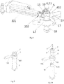
- the present application further provides a manual uncoupling device 20, which may be used for realizing manual uncoupling for couplers in a case where the crank 401 or the rotating part 402 does not operate properly.
- the manual uncoupling device 20 includes a handle 21.
- One end of the handle 21 is a rotating head 22 of a flat plate structure.
- a clamping member 23 is provided on a face of the rotating head 22.
- the number of the clamping members is equal to the number of the screws 8.
- the clamping members 23 are of a raised structure matched with the screws. As shown in Figs. 11-12 , the clamping members are two raised structures matched with mounting ports of the screws 8. When the screws 8 are protruded from the outer surface of the second rotating member 7, the clamping member 23 is of a hole structure (not shown) matched with the screws. No matter how the screws and the clamping members are matched, the operation principle is as follows: when the electric rotation or pneumatic rotation works improperly, the clamping members 23 of the manual uncoupling device 20 is matched with the screws 8 or screw holes, and the handle 21 is rotated to drive the coupler knuckle spindle 1 to rotate so as to realize uncoupling.
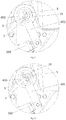
- the telescopic rod 202 is stretched out under the drive of the cylinder body 201 and then drives the crank 401 to rotate counterclockwise, and the crank 401 drives the rotating part 402 to counterclockwise rotate around the axis of the coupler knuckle spindle 1.
- the first rotating member 4 drives the second rotating member 7 to rotate counterclockwise by the work of boss 5 and the side wall 11 of the groove formed on the second rotating member 7. It can be seen from Figs. 13 and 3 that the rotation of the second rotating member 7 drives the coupler knuckle spindle 1 to rotate counterclockwise, and when two couplers can be completely uncoupled from each other, the coupler knuckle spindle 1 stops rotating.
- the telescopic rod 202 is retracted to the initial position shown in Figs. 2 and 14 . Meanwhile, due to the work of the tension spring 15, the second rotating member 7 drives the coupler knuckle spindle 1 to rotate clockwise.
- coupler knuckles 12 of two couplers are pushed to rotate counterclockwise by the thrust forces from two trains, and the coupler knuckle spindle 1 is driven to rotate counterclockwise until the two couplers 12 are rotated to the maximum angle and reach the fully opened position (that is, being rotated to the position shown in Fig. 15 ).
- the coupler knuckle spindle 1 is rotated clockwise to the initial position shown in Fig. 2 due to the tension of the tension spring 15.
- the first rotating member 4 is not rotated.
Landscapes
- Engineering & Computer Science (AREA)
- Mechanical Engineering (AREA)
- Transmission Devices (AREA)
- Hooks, Suction Cups, And Attachment By Adhesive Means (AREA)
- Quick-Acting Or Multi-Walled Pipe Joints (AREA)
- Mechanical Operated Clutches (AREA)
- Mutual Connection Of Rods And Tubes (AREA)
Claims (8)
- Mécanisme de découplage automatique pour attelage, comprenant
un axe de mâchoire d'attelage (1) et une unité d'entraînement (2) ;
l'unité d'entraînement (2) comprend un corps de cylindre (201) articulé sur un corps d'attelage (3), et un élément télescopique (202) mobile axialement le long du corps de cylindre (201) ;
moyennant quoi il comprend en outre un premier élément rotatif (4), un bossage (5) et une butée de bossage (6) ; le premier élément rotatif (4) comprend une manivelle (401) articulée à l'élément télescopique (202), et une partie rotative (402) reliée de manière fixe à la manivelle (401), la partie rotative (402) étant gainée sur l'axe de mâchoire d'attelage (1) ;
il comprend en outre un second élément rotatif (7) pour limiter le mouvement de la partie rotative (402) dans une direction axiale de l'axe de mâchoire d'attelage (1) ; et le second élément rotatif (7) est relié de manière fixe à l'axe de mâchoire d'attelage (1) ;
le bossage (5) est monté de manière fixe sur la partie rotative (402) ;
la butée de bossage (6) est disposée sur l'axe de mâchoire d'attelage (1) ou sur le second élément rotatif (7) ;
l'unité d'entraînement (2) entraîne de manière unidirectionnelle l'élément télescopique (202) de sorte que la partie rotative (402) entraîne l'axe de mâchoire d'attelage (1) en rotation unidirectionnelle par un contact du bossage (5) avec la butée de bossage (6), de manière à réaliser le découplage de l'attelage ; et,
après que l'unité d'entraînement (2) a entraîné l'élément télescopique (202) pour revenir à sa position, la rotation de l'axe de mâchoire d'attelage (1) pour réaliser un couplage d'attelage n'est pas limitée par la partie rotative (402). - Mécanisme de découplage automatique pour attelage selon la revendication 1, dans lequel, une rainure (10) est formée sur une paroi latérale de l'axe de mâchoire d'attelage (1) ou sur le second élément rotatif (7) ; la butée de bossage (6) est une paroi latérale radiale (11) de la rainure ; et une dimension de la rainure (10) dans une direction circonférentielle de l'axe de mâchoire d'attelage (1) ou du second élément rotatif (7) est supérieure ou égale à la distance de déplacement maximale du bossage (5).
- Mécanisme de découplage automatique pour attelage selon la revendication 1, dans lequel, la butée de bossage (6) est d'une structure de bloc fixée sur l'axe de mâchoire d'attelage (1) ou sur le second élément rotatif (7).
- Mécanisme de découplage automatique pour attelage selon l'une quelconque des revendications 1 à 3, dans lequel, le second élément rotatif (7) est situé au-dessus de la partie rotative (402) et est une structure de plaque de recouvrement.
- Mécanisme de découplage automatique pour attelage selon l'une quelconque des revendications 1 à 4, dans lequel l'unité d'entraînement (2) est un cylindre électrique.
- Mécanisme de découplage automatique pour attelage selon l'une quelconque des revendications 1 à 5, dans lequel, un manchon (19) est prévu entre une paroi interne du premier élément rotatif (4) et une face latérale de l'axe de mâchoire d'attelage (1).
- Mécanisme de découplage automatique pour attelage selon l'une quelconque des revendications 1 à 6, dans lequel, le second élément rotatif (7) est fixé sur l'axe de mâchoire d'attelage (1).
- Mécanisme de découplage automatique pour attelage selon l'une quelconque des revendications 1 à 7, dans lequel, le second élément rotatif (7) est fixé sur l'axe de mâchoire d'attelage (1) par deux ou plusieurs vis (8).
Applications Claiming Priority (2)
| Application Number | Priority Date | Filing Date | Title |
|---|---|---|---|
| CN201610778788.8A CN106274958B (zh) | 2016-08-31 | 2016-08-31 | 车钩自动解钩机构 |
| PCT/CN2017/097009 WO2018024260A1 (fr) | 2016-08-31 | 2017-08-11 | Mécanisme de désaccouplement automatique pour un attelage de véhicule |
Publications (3)
| Publication Number | Publication Date |
|---|---|
| EP3470295A1 EP3470295A1 (fr) | 2019-04-17 |
| EP3470295A4 EP3470295A4 (fr) | 2019-07-31 |
| EP3470295B1 true EP3470295B1 (fr) | 2020-10-28 |
Family
ID=57673724
Family Applications (1)
| Application Number | Title | Priority Date | Filing Date |
|---|---|---|---|
| EP17836441.0A Active EP3470295B1 (fr) | 2016-08-31 | 2017-08-11 | Mécanisme de désaccouplement automatique pour un attelage de véhicule |
Country Status (7)
| Country | Link |
|---|---|
| US (1) | US11072353B2 (fr) |
| EP (1) | EP3470295B1 (fr) |
| JP (1) | JP6773888B2 (fr) |
| CN (1) | CN106274958B (fr) |
| ES (1) | ES2829641T3 (fr) |
| RU (1) | RU2713578C1 (fr) |
| WO (1) | WO2018024260A1 (fr) |
Cited By (1)
| Publication number | Priority date | Publication date | Assignee | Title |
|---|---|---|---|---|
| EP4339057A1 (fr) * | 2022-09-15 | 2024-03-20 | KNORR-BREMSE Systeme für Schienenfahrzeuge GmbH | Procédé de commande d'un attelage automatique numérique de véhicules ferroviaires et un tel attelage automatique numérique |
Families Citing this family (28)
| Publication number | Priority date | Publication date | Assignee | Title |
|---|---|---|---|---|
| CN106274958B (zh) * | 2016-08-31 | 2018-02-02 | 中车青岛四方车辆研究所有限公司 | 车钩自动解钩机构 |
| CN107031680B (zh) * | 2017-04-18 | 2018-09-14 | 青岛思锐科技有限公司 | 车钩解钩控制机构 |
| CN107139960B (zh) * | 2017-05-10 | 2023-06-27 | 西南交通大学 | 超轻量化高强度过渡车钩 |
| CN108050148B (zh) * | 2018-01-26 | 2019-09-10 | 宋局 | 一种用于车厢连接的可拆挂钩机构 |
| CN108556867B (zh) * | 2018-01-26 | 2020-04-24 | 刘晓冰 | 一种基于齿轮传动的用于车厢连接的可拆挂钩机构 |
| CN108773388B (zh) * | 2018-07-25 | 2024-02-23 | 中冶赛迪工程技术股份有限公司 | 一种车钩连挂助力装置 |
| CN112172424B (zh) * | 2019-07-05 | 2024-03-29 | 中车长春轨道客车股份有限公司 | 一种自动脱钩装置和自动脱钩方法 |
| CN110566833B (zh) * | 2019-09-03 | 2020-07-17 | 深圳市海洋王照明工程有限公司 | 巡检灯 |
| DE102021132991A1 (de) | 2020-12-15 | 2022-06-15 | Voith Patent Gmbh | Automatische Zugkupplung und Verfahren zum Entkuppeln einer automatischen Zugkupplung |
| DE102021133227A1 (de) | 2020-12-15 | 2022-06-15 | Voith Patent Gmbh | Automatische Zugkupplung |
| DE102021111207A1 (de) * | 2021-04-30 | 2022-11-03 | Voith Patent Gmbh | Automatische Zugkupplung und Verfahren zum Entkuppeln einer automatischen Zugkupplung |
| DE102021111206A1 (de) | 2021-04-30 | 2022-11-03 | Voith Patent Gmbh | Automatische Zugkupplung und Verfahren zum Entkuppeln einer automatischen Zugkupplung |
| SE2150757A1 (en) * | 2021-06-11 | 2022-12-12 | Dellner Couplers Ab | Coupler comprising a blocking mechanism for preventing coupling of the mechanical coupler |
| CN113335332A (zh) * | 2021-06-18 | 2021-09-03 | 中车株洲电力机车有限公司 | 转动式自动车钩导向装置、控制方法及车钩 |
| DE102022104692A1 (de) | 2022-02-28 | 2023-08-31 | Voith Patent Gmbh | Automatische zugkupplung, spurgeführtes fahrzeug mit einer solchen automatischen zugkupplung sowie verfahren zum entkuppeln von zwei miteinander gekuppelten automatischen zugkupplungen |
| DE102022104693A1 (de) | 2022-02-28 | 2023-08-31 | Voith Patent Gmbh | Automatische zugkupplung sowie verfahren zum betreiben einer automatischen zugkupplung |
| DE102023125805A1 (de) | 2022-09-28 | 2024-03-28 | Voith Patent Gmbh | Automatische zugkupplung insbesondere für einen güterwagen eines spurgeführten fahrzeugs |
| DE102022125255A1 (de) | 2022-09-30 | 2024-04-04 | Voith Patent Gmbh | Verfahren zum auflösen und neuzusammenstellen eines zugverbunds, automatische zugkupplung sowie zugverbund |
| CN116803817B (zh) * | 2023-06-27 | 2025-11-07 | 中车制动系统有限公司 | 一种伸缩式钩缓装置自动控制系统及方法 |
| DE102023118506A1 (de) * | 2023-07-13 | 2025-01-16 | Knorr-Bremse Systeme für Schienenfahrzeuge GmbH | Digitale Automatische Kupplung (DAK) mit einem integrierten Antrieb für einen elektromechanischen Aktuator für ein Schienenfahrzeug und Schienenfahrzeug mit einer solchen Kupplung |
| DE102023129402A1 (de) | 2023-10-25 | 2025-04-30 | Pj Monitoring Gmbh | Automatische zugkupplung und verfahren zum überwachen und auflösen eines zugverbunds |
| EP4545378A1 (fr) | 2023-10-25 | 2025-04-30 | Voith Patent GmbH | Agencement et procédé de détection d'une orientation de chariot et/ou d'un rang de chariot dans un train |
| DE102023129426B4 (de) * | 2023-10-25 | 2025-08-21 | Knorr-Bremse Systeme für Schienenfahrzeuge GmbH | Digitale Automatische Kupplung (DAK) mit elektromechanischem Aktuator mit spielfreier Antriebslagerung für ein Schienenfahrzeug und Schienenfahrzeug mit einer solchen Kupplung |
| WO2025119718A1 (fr) | 2023-12-05 | 2025-06-12 | Voith Patent Gmbh | Attelage de train automatique, dispositif de découplage pour un attelage de train automatique, et véhicule ferroviaire comprenant un attelage de train automatique |
| DE102024104450A1 (de) | 2024-02-16 | 2025-08-21 | Voith Patent Gmbh | Automatische zugkupplung sowie verfahren zum betreiben einer automatischen zugkupplung |
| DE102024124818A1 (de) * | 2024-08-30 | 2026-03-05 | Kb Intellectual Property Gmbh & Co. Kg | Vorrichtung zur manuellen Entkupplung einer automatischen Kupplung für Schienenfahrzeuge im Güter- sowie Personenverkehr |
| DE102024125651A1 (de) * | 2024-09-06 | 2026-03-12 | Kb Intellectual Property Gmbh & Co. Kg | Aktuatoreinheit sowie Kupplungssystem und Schienenfahrzeugeinheit mit einer solchen Aktuatoreinheit |
| DE102025111211A1 (de) | 2025-03-24 | 2026-03-12 | Voith Patent Gmbh | Verfahren und Vorrichtung zum Entkuppeln von zwei miteinander gekuppelten automatischen Mittelpufferkupplungen eines Zugverbunds |
Family Cites Families (12)
| Publication number | Priority date | Publication date | Assignee | Title |
|---|---|---|---|---|
| NL41502C (fr) * | 1933-12-18 | |||
| JPS4634175Y1 (fr) * | 1967-06-13 | 1971-11-26 | ||
| GB1328253A (en) * | 1970-08-26 | 1973-08-30 | Mini Verkehrswesen | Arrangement for the uncoupling of rail vehicles having central buffer couplings |
| GB1314438A (en) * | 1970-12-02 | 1973-04-26 | Mini Verkehrswesen | Automatic central buffer couplings for rail vehicles |
| US4073385A (en) * | 1977-01-13 | 1978-02-14 | Walton Products, Inc. | Car coupler |
| US4391380A (en) * | 1981-02-12 | 1983-07-05 | Hoose Demetrius H | Rail car coupler interlock |
| US5503280A (en) * | 1994-04-26 | 1996-04-02 | Westinghouse Air Brake Company | Timed thrust uncoupling mechanism for passenger transit type railway cars |
| CN200981560Y (zh) * | 2006-06-28 | 2007-11-28 | 中国北车集团四方车辆研究所 | 紧凑型密接车钩 |
| DE202007001773U1 (de) * | 2007-02-07 | 2007-04-05 | Voith Ag | Kupplungsanordnung |
| CN201136515Y (zh) * | 2007-12-18 | 2008-10-22 | 中国北车集团四方车辆研究所 | 用于密接式车钩的连杆式自动解钩装置 |
| CN202439714U (zh) * | 2012-02-28 | 2012-09-19 | 齐齐哈尔轨道交通装备有限责任公司 | 铁道车辆车钩用的钩锁和铁道车辆用车钩 |
| CN106274958B (zh) * | 2016-08-31 | 2018-02-02 | 中车青岛四方车辆研究所有限公司 | 车钩自动解钩机构 |
-
2016
- 2016-08-31 CN CN201610778788.8A patent/CN106274958B/zh active Active
-
2017
- 2017-08-11 EP EP17836441.0A patent/EP3470295B1/fr active Active
- 2017-08-11 WO PCT/CN2017/097009 patent/WO2018024260A1/fr not_active Ceased
- 2017-08-11 JP JP2019505044A patent/JP6773888B2/ja not_active Expired - Fee Related
- 2017-08-11 RU RU2019101513A patent/RU2713578C1/ru active
- 2017-08-11 ES ES17836441T patent/ES2829641T3/es active Active
-
2019
- 2019-01-09 US US16/244,089 patent/US11072353B2/en not_active Expired - Fee Related
Non-Patent Citations (1)
| Title |
|---|
| None * |
Cited By (1)
| Publication number | Priority date | Publication date | Assignee | Title |
|---|---|---|---|---|
| EP4339057A1 (fr) * | 2022-09-15 | 2024-03-20 | KNORR-BREMSE Systeme für Schienenfahrzeuge GmbH | Procédé de commande d'un attelage automatique numérique de véhicules ferroviaires et un tel attelage automatique numérique |
Also Published As
| Publication number | Publication date |
|---|---|
| JP2019524545A (ja) | 2019-09-05 |
| US11072353B2 (en) | 2021-07-27 |
| US20190144013A1 (en) | 2019-05-16 |
| CN106274958B (zh) | 2018-02-02 |
| EP3470295A4 (fr) | 2019-07-31 |
| JP6773888B2 (ja) | 2020-10-21 |
| EP3470295A1 (fr) | 2019-04-17 |
| RU2713578C1 (ru) | 2020-02-05 |
| ES2829641T3 (es) | 2021-06-01 |
| CN106274958A (zh) | 2017-01-04 |
| WO2018024260A1 (fr) | 2018-02-08 |
Similar Documents
| Publication | Publication Date | Title |
|---|---|---|
| EP3470295B1 (fr) | Mécanisme de désaccouplement automatique pour un attelage de véhicule | |
| US11014584B2 (en) | Coupler telescopic apparatus and coupler | |
| CN106985877A (zh) | 车钩组件和具有其的跨坐式轨道列车 | |
| CN110422194B (zh) | 折叠车钩和车辆 | |
| CN210391159U (zh) | 折叠车钩和车辆 | |
| CN112706796B (zh) | 一种车钩用伸缩式导引装置 | |
| EP3992054B1 (fr) | Coupleur de véhicule pliable et véhicule | |
| CN102031906A (zh) | 密闭柜门快速开关装置 | |
| CN201560652U (zh) | 密闭柜门快速开关装置 | |
| CN108980205B (zh) | 滑轨锁止结构与滑轨锁止结构配装置 | |
| CN107314058B (zh) | 一种电动执行器用手电动离合装置 | |
| CN214165002U (zh) | 一种车钩用伸缩式导引装置 | |
| CN217575184U (zh) | 一种锁紧机构及开闭机构 | |
| CN214240820U (zh) | 一种车钩用折叠式导引装置 | |
| CN113669497B (zh) | 一种用于阀门执行器的直行程传动装置 | |
| CN221812325U (zh) | 一种汽车马达外壳易拆卸结构 | |
| CN219029741U (zh) | 一种飞机座椅椅腿连接机构 | |
| CN117536499B (zh) | 一种用于弯折口盖旋转锁的联动装置 | |
| CN210508788U (zh) | 一种塞拉门传动机构 | |
| CN112793614A (zh) | 一种车钩用折叠式导引装置 | |
| CN220837390U (zh) | 一种手持式轴端螺栓防松垫折角器 | |
| CN223782190U (zh) | 一种用于重型拨叉式执行器的离合式丝杆手动驱动装置 | |
| CN115036067B (zh) | 一种高速列车牵引用电系统的智能型管型母线 | |
| CN213743793U (zh) | 一种便于连接的启动器 | |
| CN120971057A (zh) | 制动系统试验定位机构 |
Legal Events
| Date | Code | Title | Description |
|---|---|---|---|
| STAA | Information on the status of an ep patent application or granted ep patent |
Free format text: STATUS: THE INTERNATIONAL PUBLICATION HAS BEEN MADE |
|
| PUAI | Public reference made under article 153(3) epc to a published international application that has entered the european phase |
Free format text: ORIGINAL CODE: 0009012 |
|
| STAA | Information on the status of an ep patent application or granted ep patent |
Free format text: STATUS: REQUEST FOR EXAMINATION WAS MADE |
|
| 17P | Request for examination filed |
Effective date: 20190114 |
|
| AK | Designated contracting states |
Kind code of ref document: A1 Designated state(s): AL AT BE BG CH CY CZ DE DK EE ES FI FR GB GR HR HU IE IS IT LI LT LU LV MC MK MT NL NO PL PT RO RS SE SI SK SM TR |
|
| AX | Request for extension of the european patent |
Extension state: BA ME |
|
| A4 | Supplementary search report drawn up and despatched |
Effective date: 20190701 |
|
| RIC1 | Information provided on ipc code assigned before grant |
Ipc: B61G 7/02 20060101ALI20190625BHEP Ipc: B61G 3/14 20060101AFI20190625BHEP Ipc: B61G 3/08 20060101ALI20190625BHEP Ipc: B61G 3/20 20060101ALI20190625BHEP |
|
| STAA | Information on the status of an ep patent application or granted ep patent |
Free format text: STATUS: EXAMINATION IS IN PROGRESS |
|
| 17Q | First examination report despatched |
Effective date: 20191021 |
|
| DAV | Request for validation of the european patent (deleted) | ||
| DAX | Request for extension of the european patent (deleted) | ||
| GRAP | Despatch of communication of intention to grant a patent |
Free format text: ORIGINAL CODE: EPIDOSNIGR1 |
|
| STAA | Information on the status of an ep patent application or granted ep patent |
Free format text: STATUS: GRANT OF PATENT IS INTENDED |
|
| INTG | Intention to grant announced |
Effective date: 20200709 |
|
| GRAS | Grant fee paid |
Free format text: ORIGINAL CODE: EPIDOSNIGR3 |
|
| GRAA | (expected) grant |
Free format text: ORIGINAL CODE: 0009210 |
|
| STAA | Information on the status of an ep patent application or granted ep patent |
Free format text: STATUS: THE PATENT HAS BEEN GRANTED |
|
| AK | Designated contracting states |
Kind code of ref document: B1 Designated state(s): AL AT BE BG CH CY CZ DE DK EE ES FI FR GB GR HR HU IE IS IT LI LT LU LV MC MK MT NL NO PL PT RO RS SE SI SK SM TR |
|
| REG | Reference to a national code |
Ref country code: GB Ref legal event code: FG4D |
|
| REG | Reference to a national code |
Ref country code: CH Ref legal event code: EP |
|
| REG | Reference to a national code |
Ref country code: AT Ref legal event code: REF Ref document number: 1327933 Country of ref document: AT Kind code of ref document: T Effective date: 20201115 |
|
| REG | Reference to a national code |
Ref country code: DE Ref legal event code: R096 Ref document number: 602017026554 Country of ref document: DE |
|
| REG | Reference to a national code |
Ref country code: DE Ref legal event code: R082 Ref document number: 602017026554 Country of ref document: DE |
|
| REG | Reference to a national code |
Ref country code: IE Ref legal event code: FG4D |
|
| REG | Reference to a national code |
Ref country code: NL Ref legal event code: MP Effective date: 20201028 |
|
| PG25 | Lapsed in a contracting state [announced via postgrant information from national office to epo] |
Ref country code: RS Free format text: LAPSE BECAUSE OF FAILURE TO SUBMIT A TRANSLATION OF THE DESCRIPTION OR TO PAY THE FEE WITHIN THE PRESCRIBED TIME-LIMIT Effective date: 20201028 Ref country code: PT Free format text: LAPSE BECAUSE OF FAILURE TO SUBMIT A TRANSLATION OF THE DESCRIPTION OR TO PAY THE FEE WITHIN THE PRESCRIBED TIME-LIMIT Effective date: 20210301 Ref country code: FI Free format text: LAPSE BECAUSE OF FAILURE TO SUBMIT A TRANSLATION OF THE DESCRIPTION OR TO PAY THE FEE WITHIN THE PRESCRIBED TIME-LIMIT Effective date: 20201028 Ref country code: NO Free format text: LAPSE BECAUSE OF FAILURE TO SUBMIT A TRANSLATION OF THE DESCRIPTION OR TO PAY THE FEE WITHIN THE PRESCRIBED TIME-LIMIT Effective date: 20210128 Ref country code: GR Free format text: LAPSE BECAUSE OF FAILURE TO SUBMIT A TRANSLATION OF THE DESCRIPTION OR TO PAY THE FEE WITHIN THE PRESCRIBED TIME-LIMIT Effective date: 20210129 |
|
| REG | Reference to a national code |
Ref country code: LT Ref legal event code: MG4D |
|
| PG25 | Lapsed in a contracting state [announced via postgrant information from national office to epo] |
Ref country code: SE Free format text: LAPSE BECAUSE OF FAILURE TO SUBMIT A TRANSLATION OF THE DESCRIPTION OR TO PAY THE FEE WITHIN THE PRESCRIBED TIME-LIMIT Effective date: 20201028 Ref country code: PL Free format text: LAPSE BECAUSE OF FAILURE TO SUBMIT A TRANSLATION OF THE DESCRIPTION OR TO PAY THE FEE WITHIN THE PRESCRIBED TIME-LIMIT Effective date: 20201028 Ref country code: IS Free format text: LAPSE BECAUSE OF FAILURE TO SUBMIT A TRANSLATION OF THE DESCRIPTION OR TO PAY THE FEE WITHIN THE PRESCRIBED TIME-LIMIT Effective date: 20210228 Ref country code: LV Free format text: LAPSE BECAUSE OF FAILURE TO SUBMIT A TRANSLATION OF THE DESCRIPTION OR TO PAY THE FEE WITHIN THE PRESCRIBED TIME-LIMIT Effective date: 20201028 Ref country code: BG Free format text: LAPSE BECAUSE OF FAILURE TO SUBMIT A TRANSLATION OF THE DESCRIPTION OR TO PAY THE FEE WITHIN THE PRESCRIBED TIME-LIMIT Effective date: 20210128 |
|
| REG | Reference to a national code |
Ref country code: ES Ref legal event code: FG2A Ref document number: 2829641 Country of ref document: ES Kind code of ref document: T3 Effective date: 20210601 |
|
| REG | Reference to a national code |
Ref country code: AT Ref legal event code: UEP Ref document number: 1327933 Country of ref document: AT Kind code of ref document: T Effective date: 20201028 |
|
| PG25 | Lapsed in a contracting state [announced via postgrant information from national office to epo] |
Ref country code: HR Free format text: LAPSE BECAUSE OF FAILURE TO SUBMIT A TRANSLATION OF THE DESCRIPTION OR TO PAY THE FEE WITHIN THE PRESCRIBED TIME-LIMIT Effective date: 20201028 Ref country code: NL Free format text: LAPSE BECAUSE OF FAILURE TO SUBMIT A TRANSLATION OF THE DESCRIPTION OR TO PAY THE FEE WITHIN THE PRESCRIBED TIME-LIMIT Effective date: 20201028 |
|
| REG | Reference to a national code |
Ref country code: DE Ref legal event code: R097 Ref document number: 602017026554 Country of ref document: DE |
|
| PG25 | Lapsed in a contracting state [announced via postgrant information from national office to epo] |
Ref country code: SK Free format text: LAPSE BECAUSE OF FAILURE TO SUBMIT A TRANSLATION OF THE DESCRIPTION OR TO PAY THE FEE WITHIN THE PRESCRIBED TIME-LIMIT Effective date: 20201028 Ref country code: RO Free format text: LAPSE BECAUSE OF FAILURE TO SUBMIT A TRANSLATION OF THE DESCRIPTION OR TO PAY THE FEE WITHIN THE PRESCRIBED TIME-LIMIT Effective date: 20201028 Ref country code: EE Free format text: LAPSE BECAUSE OF FAILURE TO SUBMIT A TRANSLATION OF THE DESCRIPTION OR TO PAY THE FEE WITHIN THE PRESCRIBED TIME-LIMIT Effective date: 20201028 Ref country code: CZ Free format text: LAPSE BECAUSE OF FAILURE TO SUBMIT A TRANSLATION OF THE DESCRIPTION OR TO PAY THE FEE WITHIN THE PRESCRIBED TIME-LIMIT Effective date: 20201028 Ref country code: LT Free format text: LAPSE BECAUSE OF FAILURE TO SUBMIT A TRANSLATION OF THE DESCRIPTION OR TO PAY THE FEE WITHIN THE PRESCRIBED TIME-LIMIT Effective date: 20201028 Ref country code: SM Free format text: LAPSE BECAUSE OF FAILURE TO SUBMIT A TRANSLATION OF THE DESCRIPTION OR TO PAY THE FEE WITHIN THE PRESCRIBED TIME-LIMIT Effective date: 20201028 |
|
| PG25 | Lapsed in a contracting state [announced via postgrant information from national office to epo] |
Ref country code: DK Free format text: LAPSE BECAUSE OF FAILURE TO SUBMIT A TRANSLATION OF THE DESCRIPTION OR TO PAY THE FEE WITHIN THE PRESCRIBED TIME-LIMIT Effective date: 20201028 |
|
| PLBE | No opposition filed within time limit |
Free format text: ORIGINAL CODE: 0009261 |
|
| STAA | Information on the status of an ep patent application or granted ep patent |
Free format text: STATUS: NO OPPOSITION FILED WITHIN TIME LIMIT |
|
| 26N | No opposition filed |
Effective date: 20210729 |
|
| PG25 | Lapsed in a contracting state [announced via postgrant information from national office to epo] |
Ref country code: AL Free format text: LAPSE BECAUSE OF FAILURE TO SUBMIT A TRANSLATION OF THE DESCRIPTION OR TO PAY THE FEE WITHIN THE PRESCRIBED TIME-LIMIT Effective date: 20201028 Ref country code: IT Free format text: LAPSE BECAUSE OF FAILURE TO SUBMIT A TRANSLATION OF THE DESCRIPTION OR TO PAY THE FEE WITHIN THE PRESCRIBED TIME-LIMIT Effective date: 20201028 |
|
| PG25 | Lapsed in a contracting state [announced via postgrant information from national office to epo] |
Ref country code: SI Free format text: LAPSE BECAUSE OF FAILURE TO SUBMIT A TRANSLATION OF THE DESCRIPTION OR TO PAY THE FEE WITHIN THE PRESCRIBED TIME-LIMIT Effective date: 20201028 |
|
| PG25 | Lapsed in a contracting state [announced via postgrant information from national office to epo] |
Ref country code: MC Free format text: LAPSE BECAUSE OF FAILURE TO SUBMIT A TRANSLATION OF THE DESCRIPTION OR TO PAY THE FEE WITHIN THE PRESCRIBED TIME-LIMIT Effective date: 20201028 |
|
| REG | Reference to a national code |
Ref country code: BE Ref legal event code: MM Effective date: 20210831 |
|
| PG25 | Lapsed in a contracting state [announced via postgrant information from national office to epo] |
Ref country code: IS Free format text: LAPSE BECAUSE OF FAILURE TO SUBMIT A TRANSLATION OF THE DESCRIPTION OR TO PAY THE FEE WITHIN THE PRESCRIBED TIME-LIMIT Effective date: 20210228 Ref country code: LU Free format text: LAPSE BECAUSE OF NON-PAYMENT OF DUE FEES Effective date: 20210811 |
|
| PG25 | Lapsed in a contracting state [announced via postgrant information from national office to epo] |
Ref country code: IE Free format text: LAPSE BECAUSE OF NON-PAYMENT OF DUE FEES Effective date: 20210811 Ref country code: BE Free format text: LAPSE BECAUSE OF NON-PAYMENT OF DUE FEES Effective date: 20210831 |
|
| PG25 | Lapsed in a contracting state [announced via postgrant information from national office to epo] |
Ref country code: CY Free format text: LAPSE BECAUSE OF FAILURE TO SUBMIT A TRANSLATION OF THE DESCRIPTION OR TO PAY THE FEE WITHIN THE PRESCRIBED TIME-LIMIT Effective date: 20201028 |
|
| PG25 | Lapsed in a contracting state [announced via postgrant information from national office to epo] |
Ref country code: HU Free format text: LAPSE BECAUSE OF FAILURE TO SUBMIT A TRANSLATION OF THE DESCRIPTION OR TO PAY THE FEE WITHIN THE PRESCRIBED TIME-LIMIT; INVALID AB INITIO Effective date: 20170811 |
|
| PGFP | Annual fee paid to national office [announced via postgrant information from national office to epo] |
Ref country code: GB Payment date: 20230824 Year of fee payment: 7 |
|
| PG25 | Lapsed in a contracting state [announced via postgrant information from national office to epo] |
Ref country code: MK Free format text: LAPSE BECAUSE OF FAILURE TO SUBMIT A TRANSLATION OF THE DESCRIPTION OR TO PAY THE FEE WITHIN THE PRESCRIBED TIME-LIMIT Effective date: 20201028 |
|
| PG25 | Lapsed in a contracting state [announced via postgrant information from national office to epo] |
Ref country code: MT Free format text: LAPSE BECAUSE OF FAILURE TO SUBMIT A TRANSLATION OF THE DESCRIPTION OR TO PAY THE FEE WITHIN THE PRESCRIBED TIME-LIMIT Effective date: 20201028 |
|
| GBPC | Gb: european patent ceased through non-payment of renewal fee |
Effective date: 20240811 |
|
| PG25 | Lapsed in a contracting state [announced via postgrant information from national office to epo] |
Ref country code: GB Free format text: LAPSE BECAUSE OF NON-PAYMENT OF DUE FEES Effective date: 20240811 |
|
| PGFP | Annual fee paid to national office [announced via postgrant information from national office to epo] |
Ref country code: ES Payment date: 20250908 Year of fee payment: 9 |
|
| PGFP | Annual fee paid to national office [announced via postgrant information from national office to epo] |
Ref country code: DE Payment date: 20250812 Year of fee payment: 9 |
|
| PGFP | Annual fee paid to national office [announced via postgrant information from national office to epo] |
Ref country code: FR Payment date: 20250828 Year of fee payment: 9 Ref country code: AT Payment date: 20250722 Year of fee payment: 9 |
|
| PGFP | Annual fee paid to national office [announced via postgrant information from national office to epo] |
Ref country code: CH Payment date: 20250901 Year of fee payment: 9 |
|
| PG25 | Lapsed in a contracting state [announced via postgrant information from national office to epo] |
Ref country code: TR Free format text: LAPSE BECAUSE OF FAILURE TO SUBMIT A TRANSLATION OF THE DESCRIPTION OR TO PAY THE FEE WITHIN THE PRESCRIBED TIME-LIMIT Effective date: 20201028 |