EP3470352A1 - Aiguillage destiné au transport de la marchandise à transporter ainsi que procédé de nettoyage d'un tel aiguillage - Google Patents
Aiguillage destiné au transport de la marchandise à transporter ainsi que procédé de nettoyage d'un tel aiguillage Download PDFInfo
- Publication number
- EP3470352A1 EP3470352A1 EP18198683.7A EP18198683A EP3470352A1 EP 3470352 A1 EP3470352 A1 EP 3470352A1 EP 18198683 A EP18198683 A EP 18198683A EP 3470352 A1 EP3470352 A1 EP 3470352A1
- Authority
- EP
- European Patent Office
- Prior art keywords
- housing
- switch
- rotary member
- axis
- rotation
- Prior art date
- Legal status (The legal status is an assumption and is not a legal conclusion. Google has not performed a legal analysis and makes no representation as to the accuracy of the status listed.)
- Granted
Links
Images







Classifications
-
- B—PERFORMING OPERATIONS; TRANSPORTING
- B29—WORKING OF PLASTICS; WORKING OF SUBSTANCES IN A PLASTIC STATE IN GENERAL
- B29B—PREPARATION OR PRETREATMENT OF THE MATERIAL TO BE SHAPED; MAKING GRANULES OR PREFORMS; RECOVERY OF PLASTICS OR OTHER CONSTITUENTS OF WASTE MATERIAL CONTAINING PLASTICS
- B29B9/00—Making granules
- B29B9/16—Auxiliary treatment of granules
-
- F—MECHANICAL ENGINEERING; LIGHTING; HEATING; WEAPONS; BLASTING
- F16—ENGINEERING ELEMENTS AND UNITS; GENERAL MEASURES FOR PRODUCING AND MAINTAINING EFFECTIVE FUNCTIONING OF MACHINES OR INSTALLATIONS; THERMAL INSULATION IN GENERAL
- F16K—VALVES; TAPS; COCKS; ACTUATING-FLOATS; DEVICES FOR VENTING OR AERATING
- F16K11/00—Multiple-way valves, e.g. mixing valves; Pipe fittings incorporating such valves
- F16K11/02—Multiple-way valves, e.g. mixing valves; Pipe fittings incorporating such valves with all movable sealing faces moving as one unit
- F16K11/08—Multiple-way valves, e.g. mixing valves; Pipe fittings incorporating such valves with all movable sealing faces moving as one unit comprising only taps or cocks
- F16K11/083—Multiple-way valves, e.g. mixing valves; Pipe fittings incorporating such valves with all movable sealing faces moving as one unit comprising only taps or cocks with tapered plug
- F16K11/0836—Multiple-way valves, e.g. mixing valves; Pipe fittings incorporating such valves with all movable sealing faces moving as one unit comprising only taps or cocks with tapered plug having all the connecting conduits situated in more than one plane perpendicular to the axis of the plug
-
- F—MECHANICAL ENGINEERING; LIGHTING; HEATING; WEAPONS; BLASTING
- F16—ENGINEERING ELEMENTS AND UNITS; GENERAL MEASURES FOR PRODUCING AND MAINTAINING EFFECTIVE FUNCTIONING OF MACHINES OR INSTALLATIONS; THERMAL INSULATION IN GENERAL
- F16K—VALVES; TAPS; COCKS; ACTUATING-FLOATS; DEVICES FOR VENTING OR AERATING
- F16K11/00—Multiple-way valves, e.g. mixing valves; Pipe fittings incorporating such valves
- F16K11/02—Multiple-way valves, e.g. mixing valves; Pipe fittings incorporating such valves with all movable sealing faces moving as one unit
- F16K11/08—Multiple-way valves, e.g. mixing valves; Pipe fittings incorporating such valves with all movable sealing faces moving as one unit comprising only taps or cocks
- F16K11/083—Multiple-way valves, e.g. mixing valves; Pipe fittings incorporating such valves with all movable sealing faces moving as one unit comprising only taps or cocks with tapered plug
- F16K11/0833—Multiple-way valves, e.g. mixing valves; Pipe fittings incorporating such valves with all movable sealing faces moving as one unit comprising only taps or cocks with tapered plug having all the connecting conduits situated in a single plane perpendicular to the axis of the plug
-
- B—PERFORMING OPERATIONS; TRANSPORTING
- B65—CONVEYING; PACKING; STORING; HANDLING THIN OR FILAMENTARY MATERIAL
- B65G—TRANSPORT OR STORAGE DEVICES, e.g. CONVEYORS FOR LOADING OR TIPPING, SHOP CONVEYOR SYSTEMS OR PNEUMATIC TUBE CONVEYORS
- B65G53/00—Conveying materials in bulk through troughs, pipes or tubes by floating the materials or by flow of gas, liquid or foam
- B65G53/34—Details
- B65G53/52—Adaptations of pipes or tubes
- B65G53/56—Switches
-
- F—MECHANICAL ENGINEERING; LIGHTING; HEATING; WEAPONS; BLASTING
- F16—ENGINEERING ELEMENTS AND UNITS; GENERAL MEASURES FOR PRODUCING AND MAINTAINING EFFECTIVE FUNCTIONING OF MACHINES OR INSTALLATIONS; THERMAL INSULATION IN GENERAL
- F16K—VALVES; TAPS; COCKS; ACTUATING-FLOATS; DEVICES FOR VENTING OR AERATING
- F16K27/00—Construction of housing; Use of materials therefor
- F16K27/06—Construction of housing; Use of materials therefor of taps or cocks
- F16K27/062—Construction of housing; Use of materials therefor of taps or cocks with conical plugs
-
- F—MECHANICAL ENGINEERING; LIGHTING; HEATING; WEAPONS; BLASTING
- F16—ENGINEERING ELEMENTS AND UNITS; GENERAL MEASURES FOR PRODUCING AND MAINTAINING EFFECTIVE FUNCTIONING OF MACHINES OR INSTALLATIONS; THERMAL INSULATION IN GENERAL
- F16K—VALVES; TAPS; COCKS; ACTUATING-FLOATS; DEVICES FOR VENTING OR AERATING
- F16K5/00—Plug valves; Taps or cocks comprising only cut-off apparatus having at least one of the sealing faces shaped as a more or less complete surface of a solid of revolution, the opening and closing movement being predominantly rotary
- F16K5/02—Plug valves; Taps or cocks comprising only cut-off apparatus having at least one of the sealing faces shaped as a more or less complete surface of a solid of revolution, the opening and closing movement being predominantly rotary with plugs having conical surfaces; Packings therefor
- F16K5/0257—Packings
- F16K5/0278—Packings on the plug
Definitions
- the invention relates to a switch for the conveyance of conveyed material and a method for cleaning such a switch.
- the DE 2 104 098 A discloses a balance valve.
- a diverter valve with a rotary plug which is displaceable in a housing between a conveying position and a cleaning position.
- the axis of rotation of the plug is arranged in the conveying plane of the pipe switch.
- the diverter valve can be cleaned with a rinsing liquid without having to remove the chick from the housing.
- the diverter allows cleaning-in-place (CIP) cleaning. Due to the arrangement of the plug between passage and outlet results in a comparatively small cone angle of the plug, which leads to a comparatively long-building chicks. Between the lang legislativedem chick and the housing of the diverter valve results in a long gap whose sealing in the delivery position can be problematic.
- a delivery pipe switch with a housing and a rotatably mounted therein rotary plug is off EP 2 332 869 B1 known.
- the transfer tube switch enables CIP cleaning.
- a complex design of the Drehkükens and the housing of the feed pipe diverter is required to ensure a circulating in all directions rinsing gap between the rotary plug and housing. CIP cleaning with the transfer tube switch is prone to error.
- a defined flushing gap can be produced between the rotary part and the housing by axially displacing the rotary part along its axis of rotation in a housing.
- the rinsing gap is defined as the vertical distance between the inside of the housing and an outside of the rotating part.
- the outside of the rotary part can be defined by the outer contour of the rotary part or a sealing element projecting thereon. Due to the axial displacement of the rotary part, the switch between a conveying position and a cleaning position can be moved.
- the rinsing gap is in particular set so that it is ensured that a supplied rinsing liquid wets and surrounds all areas of the interior of the housing and of the rotating part, ie, cleans.
- the switch on a drain opening in the housing, so that the cleaning liquid can automatically, especially due to gravity, run out of the housing.
- the switch meets the requirements for CIP cleaning.
- the fact that the rinsing gap is actively generated ensures reliable cleaning.
- the rinsing gap can be set in a range from 0.5 mm to 4 mm, in particular in a range between 1.0 mm and 3.0 mm and in particular between 1.5 mm and 2.0 mm.
- the rinse gap is sufficiently large to ensure trouble-free rinsing and cleaning of the switch.
- the housing has at least three through-openings for feeding or discharging the conveyed material, wherein the through-openings define a conveying plane.
- the axis of rotation of the rotary member is oriented perpendicular to the conveying plane. This makes it possible to divide the rotation of the rotary part on the one hand and the axial displacement of the rotary part on the other hand on two separate drives.
- the two drives can be arranged in the axial direction of the axis of rotation opposite to the rotary member. As a result, a separation of functions of the drives is possible. It is also possible to store the rotating part on both sides with respect to the axis of rotation.
- the guidance of the rotational movement of the rotating part is improved, in particular more precisely.
- This makes it possible in particular to set a radial gap between the rotary part and the housing in the conveying position of 0.01 mm to 0.5 mm.
- a pipe switch according to the DE 10 2005 061 432 A1 in which the driving axis of the plug is located in the conveying plane, is a larger cone angle for the execution of the rotating part possible. This results in advantages in the sealing of the rotating part in the housing.
- the at least partially conical design of the rotary member is limited along the axis of rotation to the portion in which the passageway extends.
- the rotary member is limited in this embodiment substantially to the passageway and the adjacent sealing area.
- the rotary part can also be designed conically sections in relation to a rotation about the axis of rotation.
- the rotary member is in particular segement-like executed with an opening angle with respect to the axis of rotation, which is smaller than 360 °, in particular less than 270 °, in particular less than 225 °, in particular less than or equal to 200 °.
- One of the through holes is a feed opening to feed conveyed the switch.
- At least two of the passage openings are discharge openings in order to discharge the conveyed material, in particular selectively, along one or the other discharge opening.
- exactly one feed opening is provided which can be selectively connected to one of the exactly two discharge openings by means of the through-channel in the rotary part.
- the switch is a distribution switch.
- the switch according to the invention can also be used as a manifold.
- at least two of the passage openings serve as feed openings in order to feed the material to be conveyed to the point.
- exactly one discharge opening is provided which can be selectively connected to one of the exactly two feed openings by means of the through-channel in the rotary part.
- the rotary member is disposed rotatably drivable about the axis of rotation in the housing.
- the rotary member has a through-channel, which connects the at least one feed opening with at least one of the discharge openings for conveying conveyed material as a function of its rotational position about the axis of rotation.
- the passageway extends along a passage longitudinal axis, which is oriented in particular straight and in particular perpendicular to the axis of rotation.
- the through channel has two through-channel openings, which are arranged on the conical outer contour of the rotary part.
- the through-passage openings each have in particular a closed outer contour.
- the housing geometry in particular has no sharp transitions.
- the production of the housing in the metal casting process is simplified, in particular with respect to DE 10 2005 061 432 A1 ,
- the risk of unwanted pore formation is reduced.
- the rotary part and a housing cover can be advantageously made of a semi-finished product. The risk of unwanted pores is thereby reduced.
- the rotary member can be rotated from a round material, in particular connecting shafts to an axial drive and a rotary drive are firmly connected to the end face of the round material.
- the connecting shafts are welded to the rotating part.
- the free ends of the connecting shafts are inserted into end-side recesses on the rotary part and then welded, ie welded.
- the housing cover may for example be made of a thick sheet.
- the rotary member and the housing cover are particularly suitable for hygienic applications of the switch, as cracks and cavities in which deposit product and could lead to contamination are avoided. Hygienic conditions for the switch are improved. It is advantageous if the drain opening is independent of the respective installation position of the switch along a conveyor line is arranged in a conveyor system each at a lowest point of the housing. As a result, the automatic drainage of the rinsing liquid is reliably ensured. It is also conceivable to provide a plurality of discharge openings on the housing in order, in particular, to provide at least one discharge opening independently of the installation position of the switch along a delivery line, via which an automatic draining of the washing liquid is ensured.
- the drainage opening has a cross-sectional area which is between 0.01 and 0.5 times the respective cross-sectional area of the passage openings, in particular between 0.02 and 0.45 times and in particular between 0.05 and 0.5 times. and 0.4 times the respective cross-sectional area of the through holes.
- the rotary member may have recesses and / or apertures which are not connected to the passageways.
- the recesses and / or openings are oriented in particular parallel to the axis of rotation, ie the recesses and / or openings extend in a direction along the axis of rotation, in particular parallel to the axis of rotation.
- the recesses and / or openings may have a round, kidney-shaped, crescent-shaped, circular segment-shaped or oval-shaped contour.
- the contour of the apertures and / or recesses is defined in a plane which is oriented perpendicular to the extension direction, in particular perpendicular to the axis of rotation. In particular, the contour of the recesses and / or openings along the breakthrough direction is constant.
- the recesses and / or openings can also be conical or doppelkonisch executed.
- the biconical design is substantially hourglass-shaped, so that the cross-sectional area of the aperture increases toward the end face of the rotary member in order to improve drainage of the cleaning fluid. In a double conical design, the drainage of cleaning fluid is improved.
- the recesses and / or breakthroughs improve the flushing of the lid portions of the switch. Because of the recesses and / or openings, the mass of the rotating part is reduced.
- An axial drive can be provided to allow the axial displacement of the rotary member along the axis of rotation.
- the rotary member can be displaced axially directly in the housing. Due to the conicity of the rotating part and the housing, the rinsing gap results directly.
- the axial drive is in particular a pneumatic drive with a cylinder.
- the axial displacement results from the stroke of the cylinder. From the stroke of the cylinder and the cone angle results in the width of the rinsing gap in the cleaning position.
- the pneumatic drive is uncomplicated and cost-effective. In principle, other drives, in particular an electric motor or a hydraulic drive are conceivable.
- an axially acting pneumatic cylinder can be provided with three different target positions.
- the middle position between the two end positions can be used to rotate the switch without creating too large a gap between the rotary part and the housing.
- When cleaning the middle position can also be used to generate additional movements of the rinsing liquid when the rotary member is moved back and forth.
- a rotary drive can be provided to allow the immediate rotationally driven displacement of the rotating part in the housing.
- the rotary drive is designed in particular as a pneumatic drive. Basically, too
- the rotary actuator can be used to move the flushing fluid.
- the rotating part With an electric motor or a hydraulic drive, the rotating part can be rotated continuously through 360 ° and generates a uniform movement in the rinsing gap.
- the rotary member In a pneumatic rotary drive, the rotary member can be swung back and forth to produce additional movement in the rinsing gap.
- the axial drive and the rotary drive are designed separately from each other. It is possible to arrange the two drives on the opposite end sides of the housing.
- the axial drive is arranged in particular on the end face with the larger end face of the housing. Due to the separate production and arrangement of the drives, the structure of the switch is simplified. The assembly costs and the manufacturing costs are reduced. During cleaning and / or switching of the switch, the drives can be moved independently of each other.
- the rotary part which is also referred to as a rotary plug, can be mounted on both sides of the housing along the axis of rotation.
- the guidance accuracy is improved and in particular allows a smaller operating gap between the outer contour of the rotary member and the inner contour of the housing.
- An arrangement of the drain opening according to claim 2 ensures a reliable drainage of the liquid from the housing regardless of the installation position of the housing along the conveyor line.
- the faces of the housing are oriented substantially parallel to the conveying plane. In the installed position of the housing such that the conveying plane is oriented horizontally, the drainage of the cleaning liquid via the then on the end face of the housing, which is arranged below the conveying plane, easily possible.
- the discharge opening is arranged in particular on the larger of the two end walls of the frusto-conical housing.
- the drain opening is then arranged in particular at a 6 o'clock position of the end wall. It is advantageous if the drain opening has a surface normal, which is oriented parallel to the axis of rotation.
- the housing may also have a plurality of drain openings, wherein a drain opening is arranged according to claim 2 at a lowest point of the housing according to the respective mounting position to improve the cleaning of the switch.
- the housing has a housing base body with a housing cover connectable therewith.
- the housing cover In the operating state of the switch, so during product promotion or during cleaning of the switch, the housing cover is connected to the housing base.
- the housing cover is designed to be removable from the housing body.
- the housing cover is detachably connected to the housing base body.
- the detachable connection is made in particular by fastening screws. It is advantageous if the inner surface of the housing cover and / or of the housing base body are designed to be inclined towards the discharge opening, at least in regions. This will be the automatic Outflow of the rinsing liquid promoted.
- the drain opening is arranged in relation to the axis of rotation in an edge region of the end face.
- the drain opening can be arranged at any position of the end face.
- the housing cover can be connected to the housing base in different rotational positions with respect to the axis of rotation.
- the housing cover can be mounted depending on the respective installation position of the switch on the housing base body so that the drain opening is arranged at the lowest point of the switch, so that an automatic drainage of a cleaning liquid is ensured.
- the construction of the switch is simplified.
- a housing cover is sufficient, which can be used for different installation positions of the switch. In particular, it is sufficient if exactly one drain opening is provided on the housing cover.
- the housing cover is flanged to the housing base body, wherein the fastening screws required for the flange connection are arranged in particular evenly distributed along the flange.
- a housing cover gasket according to claim 5 is particularly advantageous for the CIP cleaning of the switch.
- the housing cover gasket is product-contacting, ie accessible from the interior of the housing for product and flushing liquid.
- the housing cover seal is arranged without gaps. This prevents product in one Gap, in particular between the housing base body and the housing cover gasket or the housing cover gasket and the housing cover, can deposit and in particular leads to germ growth.
- a cone angle according to claim 6 enables a stable operation of the switch.
- the risk of self-locking and / or cold welding of the rotating part is reduced in the housing.
- a radial gap according to claim 7 serves for sealing the rotary part in the housing.
- the radial gap is in particular between 0.01 mm and 0.5 mm, in particular between 0.02 mm and 0.5 mm, in particular between 0.05 mm and 0.3 mm and in particular between 0.08 mm and 0.2 mm ,
- the sealing of the rotating part in the housing by means of the radial gap is also referred to as a gap seal.
- the rotary member according to claim 8 may bear directly against the inner contour of the housing.
- the rotary part abuts with the conical outer contour on the correspondingly conically shaped inner contour of the housing.
- a radial gap is then present or is 0 mm. It is conceivable to adjust the radial gap by its axial positioning along the axis of rotation in the housing and / or set in dependence on the system pressure of the rotary member in the housing when retracting the rotary member in the housing. It is particularly advantageous if the at least one of the abutting surfaces of the housing and rotating part have an increased hardness.
- the housing and the rotating part in this case form a hard-soft pairing. It is also conceivable that the surfaces of the housing and rotating part are hardened. Curing by means of a chromium layer is particularly advantageous.
- Cone sealing elements according to claim 9 ensure additional sealing of the rotating part in the housing.
- O-rings are used as cone sealing elements. O-rings are robust in use and cost-effective to use.
- through-channel sealing elements can be used to seal the through-channel.
- the through-channel sealing elements are in particular made of an elastomeric material.
- the radial gap when using the through-channel sealing elements is 0.2 mm to 2.0 mm, in particular 0.3 mm to 1.2 mm and in particular between 0.4 mm and 0.8 mm.
- the design of the switch according to claim 11 ensures a reliable and secure attachment of the passage channel sealing elements in sealing grooves of the rotary member.
- the through-channel sealing elements are arranged clamped in the sealing grooves in each case. Unintentional withdrawal of the sealing channel sealing elements from the respective groove is excluded.
- a sealing groove, in which the sealing channel sealing element can be held in a form-fitting manner, is designed in particular dovetail-shaped. It is also conceivable that the groove width increases only in one direction with increasing groove depth. It is advantageous, although the through-channel sealing element is designed substantially dovetail-shaped, at least in the section with which the through-channel sealing element is disposed within the seal groove. Other geometries for the through-channel sealing element and the sealing groove are also conceivable. It is essential that the through-channel sealing element in the sealing groove, in particular in the radial direction, is held in a form-fitting manner. The through-channel sealing element largely fills the shape of the sealing groove.
- the through-channel sealing element can be designed as a three-dimensional molded seal or as a substantially two-dimensional flat seal. Unintentional withdrawal of the passageway sealing element is prevented. The arrangement of the passageway seal member in the seal groove is reliable.
- a transitional chamfer on the through-channel sealing member according to claim 12 ensures a flush transition of the surfaces of the rotary member and the passageway channel sealing member.
- the transition chamfer is designed, for example, as a straight, inclined surface, but may in particular have a convexly shaped contour, which may in particular also be spherical, spherical or curved.
- the through-channel sealing member may include a transition portion to allow a flush transition of the surfaces of the rotating member and the passageway channel sealing member.
- the transition section may in particular at least partially straight, and in particular at least partially curved, in particular partially round, executed.
- the through-channel sealing element may be arranged in a specially shaped O-ring groove, which is completely filled by the seal.
- the sealing groove is in particular free of dead space.
- the through-channel sealing element can be designed as an O-ring with integrally molded sealing lip and / or with a specially shaped sealing contour.
- the sealing lip can abut the housing when the rotary member is retracted maximally axially in an end position in the housing.
- the sealing groove may in particular have rounded transitions and / or round and straight sections in the transition of the rotary part surface to the sealing groove.
- the passage-channel sealing element is in particular designed to be complementary to the sealing groove, wherein its sealing surface protrudes from the sealing groove with a projection section, that is to say protruding from the sealing groove.
- cross-sectional shape of the seal corresponds to the contour of the sealing groove, so that the sealing groove is filled by the seal, in particular completely.
- the rotational movement of the rotary part during cleaning that is, during the introduction of the cleaning liquid, has a rotational angle which is greater than a required rotational angle for changing the position of the rotary part for switching the passage openings.
- rotational movement and the axial movement of the rotary part take place simultaneously, that is to say superimposed rotational and axial movement takes place.
- This superimposed movement is essentially a screwing motion.
- rotational movement and axial movement of the rotary part in particular also in sections, can take place sequentially, whereby the sequence of the sequence need not be fixed. It is essential that the rotary member is transferred from a working position, in which the through-channel is defined between two through-channel openings, into a cleaning position, for which rotational and / or axial movements of the rotary member may be required.
- the cleaning of a switch is improved.
- the cleaning process is reliable and in particular in a closed state of the switch, d. H. with mounted housing cover, possible.
- the process allows for CIP cleaning.
- the rotary member is moved about the axis of rotation.
- an axial movement of the rotary member can take place along the axis of rotation.
- the switch When drying the switch by introducing hot gas, the switch can be rotatably moved about the axis of rotation and / or axially to the axis of rotation.
- the rotary member may be advantageously arranged in a rotational center position, wherein in the rotational center position of the passage channel of the rotary member is not arranged in alignment with the at least one through hole.
- the non-aligned arrangement also includes intermediate positions that deviate from the channel plane, but cause a cleaning effect for the switch.
- a method according to claim 15 enables an advantageous drying of the switch.
- both through holes in particular at the same time, can be rinsed and at the same time the rotary member is axially displaced in the rinsing position.
- the operation of the switch is improved. Due to the complete concern of the rotary part, in particular in the area of the conical design on the housing inner cone, a radial gap of up to 0 mm is performed. This means that in this embodiment, a gap-free operation is possible. To rotate the rotary part, this is slightly withdrawn in the axial direction, for example by a maximum of 0.1 mm from the housing. This results in a rotational gap between the outer contour of the rotating part and the inner contour of the housing of 0.2 mm to 2 mm. It is essential that the rotary gap is minimal, but just so large that the rotary member is rotatable in the housing.
- the rotary member In a third position, the rotary member is pulled axially into a flushing position, for example by up to 40 mm. This creates a rinsing gap with a gap width of 0.15 mm to 3.0 mm.
- the axial drive which is designed in particular as a cylinder, receives three defined positions that must be approached.
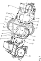
- a Fig. 1 to Fig. 12 shown point 1 is used to promote conveyed.
- the conveyed material is, for example, bulk material, in particular particulate and / or pulverulent material, for example plastic granules or particulate and / or pulverulent foodstuffs.
- the bulk material is in particular pneumatically conveyed.
- the conveyed material can also be a pasty mass and / or liquid, ie a fluid.
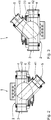
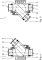
- the switch 1 is designed as a three-way switch.
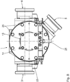
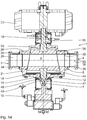
- the switch 1 has a housing 2, on which a first passage opening 3, a second passage opening 4 and a third passage opening 5 are provided.
- the passage openings 3, 4, 5 are used for supplying and / or for discharging the conveyed material.
- the passage openings 3, 4, 5, in particular the center lines of the passage openings 3, 4, 5, define a conveying plane.
- a rotary member 6 is arranged in the housing 2.
- the rotary member 6 has an axis of rotation 7 which is oriented perpendicular to the conveying plane.
- the rotary member 6 is arranged axially displaceable in the housing 2 along the axis of rotation 7.
- This gap adjustment is carried out according to the embodiment shown with a threaded sleeve 32, via the example, by means of a tool from outside of the housing 2 a stepless, so continuous axial adjustment of the rotary member 6 in the housing 2 is possible.
- the rotary member 6 is rotatably disposed in the housing 2 about the rotation axis 7.
- the rotary member 6 has a passage 8.
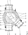
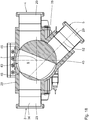
- the rotary member 6 is in particular in an in Fig. 9 illustrated outlet arrangement can be arranged, in which the first passage opening 3 with the third passage opening 5 via the passage 8 are directly connected.
- the second passage opening 4 is sealed by the rotary member 6.
- the three-way switch 1 thus allows that in the outlet arrangement the through-openings 3, 5 are connected to one another along a discharge direction 41 for conveying material, and the passage opening 4 is shut off by the rotary part 6.
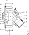
- Fig. 10 a passage arrangement in which the first passage opening 3 are connected to the second passage opening 4 via the passageway 8 with each other for material conveyance along a passage direction 42.
- the passage direction 42 is rectilinear.
- the first passage opening 3 and the second passage opening 4 are arranged on the housing 2 substantially opposite one another, in particular diametrically opposite one another.
- the third through hole 5 is sealed by the rotary member 6.
- the outlet direction 41 is angled from the first passage opening 3 to the third passage opening 5 at an outlet angle ⁇ .
- the outlet angle ⁇ is 45 °. It is advantageous if the outlet angle ⁇ is between 30 ° and 90 °, in particular between 40 ° and 60 ° and in particular between 42 ° and 50 °.
- the rotary member 6 is designed with respect to its axis of rotation 7 substantially as a truncated cone, that is, at least in sections along the axis of rotation 7 has a conical outer contour 9. As shown in Fig. 6 the axis of rotation is the explosion axis.
- the passage 8 is oriented perpendicular to the axis of rotation 7. The passage is arranged eccentrically with respect to the axis of rotation 7 on the rotary member 6.
- the truncated cone geometry of the rotary part 6 is limited by a larger end face 10 and a smaller end face 11.
- the end faces 10, 11 are each oriented perpendicular to the axis of rotation 7 and executed plan according to the embodiment shown.
- the end faces 10, 11 can also be convex in each case and in particular at least partially inclined and / or curved.
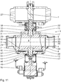
- an axial drive shaft 12 is attached to the rotary member 6.
- the axial drive 15 is designed as a pneumatic drive, in particular as a pneumatic cylinder, in particular as a linear actuator.
- the axial drive 15 can also be designed as an electric motor or hydraulic cylinder.
- the axial drive 15 allows a driven axial displacement of the rotary member 6 in the housing 2 along the axis of rotation 7.
- the axial drive 15 may be designed with an intermediate position, which allows to move the rotary member 6 in the housing 2 along the axis of rotation 7 in an axial intermediate position.
- the switch 1 In the axial intermediate position of the rotary member 6 in the housing 2, the switch 1 can be operated and / or rotated with a small gap between 0.01 mm and 0.5 mm.
- the coupling 47 allows a directed in the axial direction of the axis of rotation 7 connection between the axial drive 15 and the axial drive shaft 12 for the transmission of axial forces.
- the clutch 47 With respect to the axis of rotation 7, the clutch 47 is executed torque-free. A rotational movement of the rotary member 6 is not transmitted to the axial drive 15 by the clutch 47.
- the coupling 47 is sleeve-shaped in the embodiment shown with one of the axial drive shaft 12 facing, radially inwardly directed annular collar 48.
- annular collar 48 engages behind an annular disk section 49 of the axial drive shaft 12.
- the annular disk section 49 is rotatably arranged in the sleeve section of the coupling 47.
- the annular disc portion 49 is integrally formed on the axial drive shaft 12 and arranged on the front side of the axial drive shaft 12.
- cone-sealing elements 16 are provided, which are arranged with respect to the axis of rotation 7 spaced from each other on the rotary member 6.
- the cone sealing elements 16 are each designed according to the embodiment shown as an O-ring.
- the cone sealing elements 16 serve to seal the conical surface, that is to say the conical outer contour 9 on the corresponding inner contour 17 of the housing 2.
- the cone sealing elements 16 are each arranged adjacent to the larger end face 10 and the smaller end face 11.
- the through-channel 8 is arranged along the axis of rotation 7 between the two cone-sealing elements 16.
- a rotary drive shaft 18 is attached to the rotary member 6, which can be led out through a second opening 19 in the housing base 20, which is in particular made in one piece with the housing base body 21.
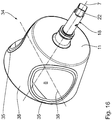
- the rotary drive shaft 18 has at least in sections along the axis of rotation 7 to a torque transmitting portion 22 which is executed out of round in the plane perpendicular to the axis of rotation 7 and according to the embodiment shown has an outer square geometry.
- the torque transmission section 22 the rotary drive shaft 18 can be coupled to a rotary drive 23 in a torque-transmitting manner.
- the rotary drive 23 can the rotary member 6 are rotatably driven in the housing 2 with respect to the rotation axis 7.
- the rotary drive 23 is designed as a pneumatic rotary drive.
- the rotary drive 23 can also be designed as an electric motor, hydraulic motor or hydraulic cylinder.
- the rotary drive 23 allows rotation of the rotary member 6 between the outlet assembly according to Fig. 9 and the passage arrangement according to Fig. 10 ,
- pocket-shaped depressions 45 are provided on the inner surfaces.
- the recesses 45 each cooperate with a corresponding free-form surface 46 in the passage 8 of the rotary member 6.
- the pocket-shaped recesses 45 are formed in the housing 2 asymmetrically with respect to a longitudinal center plane 50, which is spanned by the axes 36, 52 of the through holes 3, 4, 5.
- the longitudinal center plane 50 corresponds to the plane of the drawing Fig. 9 and 10 , In particular, in the order of departure according to the Fig. 9 but also in the passage arrangement according to Fig. 10 is a transition at the passage 8 edge-free, so bum-free executed.
- a geometric impact is avoided by the adaptation of the contours in the connecting piece 28 and in the passage 8. Regarding the avoidance of geometric shock is on the DE 39 22 240 C2 directed.
- a drain opening 24 is provided according to the embodiment shown, to which a drainage bend 25 is attached.
- the discharge manifold 25 is welded in particular to the housing cover 14.
- the discharge manifold 25 forms part of the drain line.
- the drain opening 24 is integrated in the housing cover 14.
- the housing cover 14 has an inclined Inner surface, which is designed inclined to the drain opening 24.
- the inner surface of the housing cover 14 is designed sloping outwards.
- the drain opening 24 is arranged in relation to the axis of rotation 7 in particular at a maximum radially spaced.
- the drain opening 24 is arranged in a horizontal installation position, in which the housing cover 14 is oriented vertically, at a lowest point of the housing 2 of the switch 1. Via the discharge opening 24 and the discharge manifold 25, a liquid can automatically drain from the interior of the housing 2 as a result of gravity.
- the housing cover 14 can be screwed in different rotational positions about the rotation axis 7 with the housing base body, it is sufficient to provide exactly one drain opening 24 on the housing cover. Depending on the installation position of the switch 1, the housing cover 14 can be screwed to the housing base body 21 so that the drain opening 24 forms the lowest point of the housing 2.
- the housing cover 14 is screwed to the housing base 21 by means of a plurality of fastening screws 26.
- the housing cover 14 is arranged sealed to the housing base 21 by means of a circumferential annular seal 27.
- the ring seal 27 is a housing cover seal.
- the ring seal 27 is made freely accessible from the interior of the housing 2 of the switch 1.
- the ring seal 27 is designed to contact the product.
- the ring seal 27 allows a wet cleaning of the housing 2, without the housing 2 has to be opened for this purpose.
- the switch 1 can be cleaned liquid in the closed state.
- the diverter 1 allows a liquid cleaning under cleaning in place hygiene requirements.
- the outer contour 9 of the rotary member 6 is performed with the cone angle ⁇ .
- the cone angle ⁇ is shown in FIG Embodiment 20 °. It is advantageous if the cone angle ⁇ is between 5 ° and 80 °, in particular between 10 ° and 40 °, in particular between 15 ° and 25 °.
- connecting stubs 28 formed in one piece on the housing base 21 are each formed on the passage openings 3, 4, 5.
- To the connecting piece 28 may advantageously be a pipe socket 29 sealed flanged by means of a product-contacting flange seal 30.
- a pipe socket 29 sealed flanged by means of a product-contacting flange seal 30.
- the pipe socket 29 can be easily screwed to the housing. This makes it possible to adapt the switch 1 by suitable selection of the pipe socket 29 to the required pipe cross-section and flange connection of a conveyor system.
- the turnout can be flexibly and easily integrated into an existing conveyor system.
- the rotary member 6 is first arranged sealed in the housing 2.
- the rotary member 6 is pressed by means of the axial drive 15 along the axis of rotation 7 in the housing 2 until the rotary member 6 is arranged with a defined radial gap between the outer contour 9 and the inner contour 17 in the housing 2.
- the radial gap is in particular between 0.01 mm and 0.5 mm, in particular between 0.02 mm and 0.5 mm, in particular between 0.05 mm and 0.3 mm, and in particular between 0.08 mm and 0.2 mm.
- the rotary member 6 is sealed by means of the cone sealing elements 16 in the housing 2.
- the rotary member 6 is in a conveying position, which is also referred to as a conveyor assembly.
- the gap seal can also be embodied without the cone sealing elements 16.
- a material delivery via the interconnected through holes 3, 5 and 4, 5 along the through-channel 8 is possible sealed.
- the rotary member 6 is rotated about the rotation axis 7 by means of the rotary drive 23.
- the rotation of the rotary part 6 and the axis of rotation 7 can take place in the conveying arrangement of the rotary part 6 in the housing 2.
- the rotary member 6 is rotatable in the sealed arrangement in the housing 2 about the axis of rotation 7.
- the rotary part 6 can be pulled out of the sealed arrangement along the axis of rotation 7 in the housing 2 before the rotary movement, ie be displaced towards the axial drive 15.
- a cleaning of the switch 1 is carried out in particular first a purging of the through-channel 8 via the conveyor lines connected to the switch 1 in the passage direction 42 and in the outlet direction 41, wherein the rotary member 6 remains in particular in the conveying position. Subsequently, the rotary member 6 is displaced axially along the axis of rotation 7 in the housing 2 to the housing cover 14.
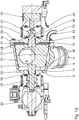
- the flushing arrangement of the switch 1 is in Fig. 12 shown.
- the housing 2 has a free space 44 into which the rotary part 6 with the larger end face 10 can be displaced. During the axial displacement of the rotary member 6, the housing 2 remains closed.
- an opening of the housing 2 is not required.
- the cleaning gap 31 has a size of about 1.5 mm to 2.0 mm. It is advantageous if the cleaning gap 31 has a size of 0.5 mm to 4 mm, in particular between 1.0 mm to 3.0 mm.
- the cleaning gap 31 is also referred to as a rinsing gap.
- the cleaning gap 31 makes it possible for cleaning liquid, which is supplied into the housing 2, for example via the passage openings 3, 4, 5, also the surface sections of the outer contour 9 of the rotary part 6, the inner contour 17 of the housing 2 and the inner surface of the housing cover 14 with cleaning liquid wetted.
- the entire interior of the housing 2, in particular the gap between the outer contour 9 and the inner contour 17, can be rinsed with cleaning fluid.
- the cleaning arrangement according to Fig. 12 is also referred to as flushing arrangement.
- FIG. 12 shows the switch 1 in an installed position, in which the housing cover 14 is oriented vertically.
- the passage direction 42 is oriented horizontally.
- the departure direction 41 is directed obliquely downwards.
- the conveying plane is vertically oriented. This arrangement is shown schematically in FIG Fig. 2 shown.
- the passage direction 42 is oriented vertically with a departure direction 41 obliquely above (see. Fig. 4 ) or obliquely downwards (cf. Fig. 5 ).
- the conveying plane is oriented vertically.
- the housing cover 14 is oriented vertically.
- the switch can also be used when the housing cover 14 is oriented horizontally. It is advantageous if the housing cover 14 is arranged in the horizontal mounting position on the upper side of the housing 2. The removal of the rotating part 6, in particular for maintenance and / or cleaning purposes is simplified. In principle, the arrangement in which the housing cover 14 is oriented horizontally and arranged on the underside of the housing 2 is also conceivable.
- the mounting position and the nature of the seal of the rotary member 6 in the housing 2 are independent of each other. Every possible type of seal of the rotating part in relation to the housing can be used in any mounting position.
- Fig. 13 shows a further embodiment of a switch 1, wherein the axial adjustment of the rotary member 6 takes place in the housing 2 by means of a spacer 33. As a result, the positioning of the rotary member 6 in the housing 2 is clearly defined.
- the substantially annular openings of the passage channel 8 each have a circumferential through-passage sealing element 35 on.
- the through-channel sealing elements 35 are arranged circumferentially on the outer contour 9 of the rotary part 34.
- the arrangement and in particular the positioning of the rotary member 34 in the housing 2 are otherwise substantially unchanged.
- An essential difference compared to the previous embodiment is that the sealing gap between the outer contour 9 of the rotary member 34 and the inner contour 17 of the housing 2 is increased.
- the radial gap is in particular between 0.1 mm and 2.0 mm, in particular between 0.2 mm and 2.0 mm, in particular between 0.3 mm and 1.2 mm and in particular between 0.4 mm and 0.8 mm ,
- the rotary member 34 can be pulled axially along the longitudinal axis 7 of the housing 2 at least partially. It is preferred if the rotary member 34 is rotated in the conveying position in the housing 2.
- the rotary member 34 is rotatably disposed with the passageway seal members 35 in the housing 2. For a rotatability of the rotary member 34 about the rotation axis 7, it is not necessary to axially displace the rotary member 34 in the housing 2.
- the circumferential sealing groove 37 is designed substantially dovetailed or trapezoidal, ie the groove width b increases with increasing groove depth t.
- the dovetailed or trapezoidal contour may be rounded in the corner areas. It is particularly conceivable that only individual or all corner areas are rounded.
- the flank angle of the dovetail-shaped or trapezoidal contour is in particular greater than 45 °, in particular greater than 60 °, in particular greater than 75 °, in particular greater than 80 °, in particular greater than 85 ° and in particular greater than 88 °. In any case, the flank angle is less than 90 °.
- a flank angle of 90 ° would mean a rectangular contour of the sealing groove 37.
- the groove width b grows at least in a width direction.
- the passageway seal member 35 is reliably held in the groove 37.
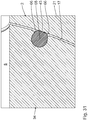
- the groove width in the area of the surface 38 of the rotary part 34 is smaller than the width of the through-channel sealing element 35 in an initial state.
- the passageway seal member 35 is biased in the groove 37 on the surface 38 and clamped in Nutbreitenraum clamped.
- the width of the passageway seal member may also increase with increasing groove depth t.
- the contour of the portion of the through-channel sealing element 35, which is arranged within the groove 37, is also substantially dovetailed, wherein the width increases at least in particular in one direction.
- the contour of the portion of the passageway sealing member 35 disposed in the groove 37 is substantially identical to the groove cross-section.
- the maximum width of the through-channel sealing element 35 is in particular greater than the opening of the groove 37 facing the surface 38 of the rotary part 34.
- the through-channel sealing element 35 fills the groove 37 completely, in particular.
- the through-passage sealing element 35 is arranged gap-free and dead space in the groove 37.
- the entire surface of the groove 37 is covered by the through-channel sealing member 35.
- the passage-channel sealing element 35 abuts the entire surface of the groove 37 on the entire surface.
- the passageway seal member 35 is made of an elastomeric material.
- the through-channel sealing element 35 protrudes out of the groove 37 on the surface 38 of the rotary part 34 according to the embodiment shown. As a result, a sealing effect of the through-channel sealing element 35 is improved.
- the supernatant D with respect to the surface 38 is according to the embodiment shown in particular between 0.5 mm and 1.0 mm.
- the cross-sectional shape of the passageway seal member 35 is substantially rectangular, with the projection portion of the passageway seal member 35 protruding from the groove 37 having transient lands 39.
- the transitional chamfers 39 enhance the sealing effect on the rotary member 34.
- the transitional chamfers 39 allow a smooth transition from the surface 38 of the rotary member 34 to the surface 43 of the through-channel sealing member 35.
- the rotary member 34 In order to flush the switch 1 with through-channel sealing elements 35, the rotary member 34 is axially displaced the housing 2 as in the previous embodiment, until the rinsing gap is present. Since the through-channel sealing elements 35 project beyond the outer contour 9 of the rotary part 34, in this embodiment the rinsing gap is the distance between the inner contour 17 of the housing 2 and the passageway sealing elements 35 set.
- the so-defined rinse gap is identical for this embodiment with the rinsing gap of the switch 1 with gap seal.
- the rinse water can escape from the housing 2 of the switch 1.
- the rotary member 40 is executed without sealing element according to the embodiment shown.
- a seal of the rotary member 40 in the housing 2 is achieved in that the rotary member 40 rests with the conical outer contour 9 directly to the conical inner contour 17 of the housing 2. It is said that the rotary member 40 is set relative to the housing 2 to block. In this arrangement, no radial gap is provided or the radial gap is 0 mm.
- at least one of the adjoining surfaces has a specific surface treatment and in particular has a surface finish, in particular has a particular surface hardness. It is also possible to provide the surfaces of both components, that is to say the housing 2 and the rotary part 40, with a hardening layer. It is advantageous if the surfaces have a chromium layer as a hardening layer. It is advantageous if only the surface of the rotary member 40 is designed with the chromium layer.
- the switch For rotating the switch, in which the rotary member 40 is set in block in the housing, it is necessary to remove the rotary member 40 from the housing 2. This can be done for example by a relatively small axial adjustment of a few tenths of a millimeter to a few millimeters.
- the small axial adjustment of the rotary member 40 can be effected in that the pneumatic lifting drive, that is, the axial drive 15, is depressurized.
- the rotary member 40 is lifted from the cone inner contour 17 of the housing 2.
- this can be rotated between the passage arrangement and the outlet arrangement.
- the rotary member 40 can also be rotated about the axis of rotation 7 in order to scrape and discharge possible product deposits.
- the rotary member 40 is further pulled out of the housing 2 along the axis of rotation 7 until a larger, defined rinsing gap is formed.
- the Axialverlagern the rotary member 40 may also be carried out in one stage, in particular, a relief element is dispensed with Drucklosschalt the axial drive 15. The turning and cleaning of the rotary member 40 is then carried out in a maximum axially displaced state, ie in the flushing arrangement.
- Fig. 18 the function, in particular the rinsing of a switch explained in more detail.
- Fig. 18 is the rotary member 40 in the axialverlagerten state.
- the rotary member 40 is rotated about the longitudinal axis 7, is thus located neither in the passage arrangement nor in the outlet arrangement, but in a scavenging rotational position in which the passage channel 8 none of the through holes 3, 4, 5 faces.
- the first passage opening 3 and the pipe section connected thereto are largely blocked by the rotating part 40.
- Rinse water which is pressed into the side cover area due to the gap, flows intensively through this side cover area.
- the rinse water is then rinsed through another column in one of the purging pipe sections, which are connected to the through holes 4 and / or 5. It is advantageous that the rotary drive 23 of the switch 1 allows the flushing position of the rotary member 40 with a third center position.
- cleaning liquid can emerge at the drain opening 24 in order to better rinse the side area between the housing 2 and the rotary part 6, or between the cover 14 and the rotary part 6.
- the flushing water is discharged through the drain opening 24.
- the rotary drive 23 in the in Fig. 18 center position shown are driven.
- the rotary member can also be moved axially, so that sufficient turbulence of the flow is generated, and in particular to safely dry all areas of the switch 1 and the rotary member 40 and to remove larger amounts of the rinse water from possible dead zones.
- FIG. 19 Structure and function of a further embodiment of a switch explained, in which the drain opening 24 is arranged on the housing bottom 20.
- This switch 1 can be used in an installed position in which the housing cover 14 is made horizontal and disposed on an upper side of the housing 2.
- the housing bottom 20 and in particular the outlet opening 24 arranged radially on an outer side forms the lowest point of the housing 2, so that cleaning fluid, as explained above, can automatically run out of the housing 2 due to gravity without an opening of the housing 2 is required.
- the housing bottom 20 is executed inclined to the drain opening 24.
- the drain opening 24 has a radial distance with respect to the axis of rotation 7 such that the drain opening is arranged in the region of the outer circumference of the housing bottom 20. It is also conceivable to arrange the drain opening 24 with a smaller radial distance on the housing bottom 20.
- the housing bottom 20 is designed plan. It is conceivable that in the housing bottom 20, a gutter is integrated, according to the sectional view in Fig. 19 is executed substantially v- or U-shaped and is designed with a slope to the drain opening 24 toward. As a result, rinsing liquid can be specifically and reliably discharged to the drain opening 24.
- the shape of the housing bottom 20 depends in particular on the installation position of the switch 1.
- FIGS. 20 to 22 Another embodiment of a switch explains.
- the switch 53 differs from the previous switches in that on the housing 54, a second drain opening 55 and on the rotary member 40, an opening 57 are provided.
- the switch 53 may also be listed with only one drain opening 24 and opening 57 in the rotary member 40.
- the switch 53 may also be designed with the two drain openings 24, 55, but without breakthrough 57. The provision of the second drain opening 57 is possible regardless of whether the opening 57 is provided on the rotary part 40.
- the second drain opening 55 is arranged on the front side of the housing 54.
- the second drain opening 55 is arranged in the housing bottom 20.
- the first drain opening 24 is arranged on the housing cover 14, in particular in a radial outer region of the housing cover 14.
- the first drain opening 24 is arranged at a lowest point of the housing.
- the rotary member 56 substantially corresponds to the rotary member 40 according to the previous embodiment, wherein an opening 57 is additionally provided.
- the opening 57 is substantially cylindrical and has at the end faces 10, 11 of the rotary member 56 facing transitions chamfers 58.
- the aperture 57 has a breakthrough longitudinal axis 59, which is oriented parallel to the longitudinal axis 7 of the switch 53.
- the opening 57 leads to a reduction in the mass of the rotating part.
- the flushing of the switch 53 is improved, in particular in the area of the side surfaces. It is essential that the opening 57 of at least one of the end faces 10, 11 of the rotary member 56 extends from. It is also conceivable to provide a blind hole-like recess instead of the opening, which extends along the longitudinal axis of the breakthrough 59, but is not carried out continuously by the rotary member 56.
- the breakthrough longitudinal axis 59 can be arranged with an angle of inclination relative to the longitudinal axis 7. This angle of inclination can be up to 20 °.
- the breakthrough longitudinal axis 59 is oriented in particular perpendicular to the through-channel longitudinal axis 36.
- the through-passage longitudinal axis 36 and the breakthrough longitudinal axis 59 are so skewed oriented to each other that the passageway 8 and the opening 57 are separated from each other in the rotary member 56.
- the aperture 57 is spaced from the passageway 8 in the rotary member 56 integrated.
- the passage 8 and the opening 57 are not interconnected.
- the breakthrough 57 is a relief hole.
- the opening 57 makes it possible to improve the cleaning result. As soon as liquid, in particular water, exits via one of the lateral outflow openings of the opening 57, the end faces of the rotary part 56 are better lapped.
- the rotary member 60 substantially corresponds to the rotary member 56, wherein the opening 57 is designed slot-shaped along a circular arc.
- the opening angle ⁇ of the circular arc with respect to the longitudinal axis 7 is according to the embodiment shown 90 °.
- the opening angle ⁇ can also be more than 90 ° or less than 90 °.
- the slot width B is the embodiment shown half of the radius of the smaller end face 11.
- the slot width B can be selected larger or smaller. It is advantageous if the opening 57 is as large as possible in order to reduce as much mass as possible of the rotary part 60. In the embodiment of the opening 57, it should be noted that the opening 57 and the through-channel 8 do not intersect. The stability and rigidity of the rotary member 60 is ensured despite the opening 57.
- the rotary member 61 substantially corresponds to the rotary member 56 according to the previous embodiment.
- the main difference is that the opening 57 is double-conical.
- the opening 57 tapers with a breakthrough cone angle ⁇ .
- the breakthrough cone angle ⁇ is 1 °.
- the breakthrough cone angle ⁇ can also be chosen to be greater or smaller than 1 °. It is advantageous if the breakthrough cone angle ⁇ promotes an automatic drainage of cleaning liquid from the opening to the end faces 10, 11 in the opening 57.
- the doppelkonische execution of the aperture 57 is symmetrical. This means that the cone portions of the opening 57 meet in the longitudinal center plane 50, in which the through-channel longitudinal axis 36 is located.
- the two breakthrough cone angles ⁇ of the cone sections of the aperture 57 are identical. It is also conceivable that the depth of the cone sections of the aperture 57 are different from each other and meet in particular outside the longitudinal center plane 50.
- the breakthrough cone angles ⁇ can also be set differently.
- Fig. 25 to 27 another embodiment of a rotary member 62 explained.
- the essential difference compared to the previous embodiments is that the outer contour 9 of the rotary member 62 is not made completely conical.
- the outer contour extends over an opening angle ⁇ with respect to the longitudinal axis 7, wherein the opening angle ⁇ is more than 180 °. According to the embodiment shown, the opening angle ⁇ is 200 °.
- the rotary member 62 corresponds to a segment of a cone.
- invisible outside 63 of the rotary member 62 is executed plan.
- the outer surface 63 opposite surface is partially straightened.
- the straightened portion 64 is made parallel to the outside 63.
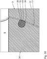
- the passage-channel sealing element 35 is designed essentially as an O-ring, which is arranged in a corresponding sealing groove 37.
- the cross-sectional shape of the through-channel sealing element 35 and the contour of the seal groove 37 correspond to each other, so that the seal groove 37 is completely filled by the passage-channel sealing member 35. Dead spaces are avoided.
- the passageway seal member 35 has a projection portion comprising two transition lands 39 meeting in a substantially line-shaped surface 43.
- the line-shaped surface 43 forms a contact edge of the through-channel sealing element 35 on the inner contour 17 of the housing 2.
- FIG. 31 another embodiment of the through-channel sealing element explained.
- the passageway sealing member 65 is like the embodiment according to FIG Fig. 30 executed essentially O-ring-shaped.
- the only difference is that the supernatant section instead of the supernatant chamfer has supernatant roundings 66, which show a transition into a substantially planar surface 43.
- the contact surface in the region of the surface 43 of the through-channel sealing element 65 with the inner contour 17 of the housing 2 is thereby increased.
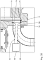
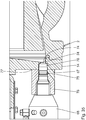
- the switch which in Fig. 32 is shown in sections, has a valve with a valve body 67, which is designed in the form of a cylinder head valve.
- the drain opening 24 can be temporarily opened and closed.
- the outflow of liquid, in particular of cleaning liquid through the drain opening 24 can be controlled by means of the valve.
- the Valve be opened, in particular to improve the air supply and in particular in the area adjacent the drain opening 24 to improve the drying behavior.
- the valve body 67 is arranged on the drain opening 24.
- valve body 67 terminates flush with the inner contour of the housing, in particular with the inner contour of the housing cover 14. A dead space in which product and / or cleaning liquid, in particular from the cleaning cycle, can collect is avoided. It is ensured that the interior of the housing 2 is cleaned without residue. Residues in the housing 2 of the switch 1 are avoided.
- valve body 67 is connected by means of a valve body actuator 68 between the in Fig. 32 shown closing arrangement and an opening arrangement displaced.
- the direction of displacement for the valve body 67 is oriented transversely and in particular perpendicular to the housing cover 14 into the housing 2.
- the displacement direction for the valve body 67 is oriented perpendicular to the plane of the drain opening 24. Due to the displacement of the valve body 67, the drain opening is released.
- the valve body 67 is designed with a valve rod 69 and a valve disc 70 arranged on the end side.
- the valve disk 70 is integrally connected to the valve rod 69.
- the valve disk 70 is in the closing arrangement according to Fig. 32 sealed at the drain opening 24.
- a valve body seal 71 which is designed according to the embodiment shown as an O-ring on the drain opening 24 in the housing cover 14 integrated.
- the valve body seal 71 is fixed to the housing arranged.
- the valve body seal 71 is designed to contact the product.
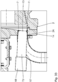
- valve body 67 is designed as a stamp aligned obliquely.
- the displacement direction for the valve body 67 is oriented transversely to the longitudinal axis 7 of the switch.
- the punch 72 has a substantially constant thickness, in particular a constant cross-sectional area, along the displacement direction.
- the valve body seal 71 is arranged in the region of the end face 73 of the punch 72.
- the end face 73 faces the interior of the housing 2 of the switch 1.
- the valve body seal 71 is arranged in particular on the punch 72. With a displacement of the punch 72 for closing and opening the drain opening 24 and the valve body seal 71 is displaced.
- the valve body seal 71 is not fixed to the housing, but mounted valve body fixed.
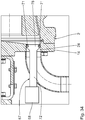
- Fig. 34 another embodiment of a switch with valve body explained.
- the conicity of the head 78 corresponds to the conicity of the drain opening 24 in the housing cover 14.
- the valve body seal 71 is attached to the valve body 67, in particular to the head 78.
- valve body 67 is designed with a head 78 having a front, Having the interior of the housing 2 facing cone portion 74.
- the cone section 74 allows a sealing arrangement in the drain opening 24 in the housing cover 14 of the housing 2.
- a valve body seal 71 can be arranged on the head 78.
- the displacement direction of the valve body 67 is oriented parallel to the longitudinal axis 7 of the switch 1.
- a drain line 75 is provided, which serves for drainage of cleaning liquid from the switch 1.
- a non-illustrated drain cock 25 can be connected to the drain line 75.
- the drain line 75 is branched out of the drain opening 24 in a direction transverse to the displacement direction of the valve body 67.
- a connecting body 76 is attached to the housing cover 14, in particular by means of a circumferential weld seam 77 welded.
- the connecting body 76 ensures the guided and exactly positioned arrangement of the valve body 67 with respect to the housing cover 14, ie the drain opening 24.
- the drainage conduit 75 is at least partially integrated in the connecting body 76.
- the connecting body 76 also serves to receive and hold the valve body actuator 68.
Landscapes
- Engineering & Computer Science (AREA)
- General Engineering & Computer Science (AREA)
- Mechanical Engineering (AREA)
- Multiple-Way Valves (AREA)
- Cleaning By Liquid Or Steam (AREA)
Applications Claiming Priority (1)
| Application Number | Priority Date | Filing Date | Title |
|---|---|---|---|
| DE102017218031 | 2017-10-10 |
Publications (2)
| Publication Number | Publication Date |
|---|---|
| EP3470352A1 true EP3470352A1 (fr) | 2019-04-17 |
| EP3470352B1 EP3470352B1 (fr) | 2023-08-09 |
Family
ID=63762403
Family Applications (1)
| Application Number | Title | Priority Date | Filing Date |
|---|---|---|---|
| EP18198683.7A Active EP3470352B1 (fr) | 2017-10-10 | 2018-10-04 | Aiguillage destiné au transport de la marchandise à transporter ainsi que procédé de nettoyage d'un tel aiguillage |
Country Status (5)
| Country | Link |
|---|---|
| US (1) | US11174955B2 (fr) |
| EP (1) | EP3470352B1 (fr) |
| CN (1) | CN109654257B (fr) |
| DE (1) | DE102018217035A1 (fr) |
| DK (1) | DK3470352T3 (fr) |
Cited By (2)
| Publication number | Priority date | Publication date | Assignee | Title |
|---|---|---|---|---|
| WO2021067759A1 (fr) | 2019-10-03 | 2021-04-08 | Flowtrend, Inc. | Valve sanitaire à écoulement complet |
| US11913560B2 (en) | 2019-10-03 | 2024-02-27 | Process Innovation—Food Safety, Llc | Full-flow sanitary valve |
Families Citing this family (7)
| Publication number | Priority date | Publication date | Assignee | Title |
|---|---|---|---|---|
| CN110081206B (zh) * | 2019-04-29 | 2020-08-28 | 合肥美的暖通设备有限公司 | 阀芯控制方法、混水阀和计算机可读存储介质 |
| CN110345280A (zh) * | 2019-08-02 | 2019-10-18 | 郭勇 | 一种砂浆喷涂三通阀 |
| EP3792527A1 (fr) | 2019-09-10 | 2021-03-17 | Alfa Laval Corporate AB | Joint, soupape de régulation de flux de fluide et procédé de nettoyage d'une telle soupape |
| EP3795508B1 (fr) * | 2019-09-20 | 2023-06-07 | Sesotec GmbH | Filtre séparateur de matériau et dispositif de séparation |
| CN111779911B (zh) * | 2020-05-22 | 2021-11-09 | 云南锡业股份有限公司冶炼分公司 | 一种高温液态金属自动控制换向阀 |
| NL2033931B1 (en) | 2023-01-10 | 2024-07-18 | Dmn Machf Noordwykerhout B V | Diverter valve |
| CN117886126B (zh) * | 2024-03-18 | 2024-05-07 | 江苏恒东机械有限公司 | 一种粉末物料定量气力输送装置 |
Citations (5)
| Publication number | Priority date | Publication date | Assignee | Title |
|---|---|---|---|---|
| DE355796C (de) * | 1918-01-31 | 1922-07-03 | William Oran Renkin | Umschalthahn bei Luftfoerderanlagen fuer Schuettgut, insbesondere Staubkohle |
| US1725337A (en) * | 1928-05-03 | 1929-08-20 | White Eagle Oil And Refining C | Valve |
| FR1592242A (fr) * | 1968-10-31 | 1970-05-11 | ||
| EP0994050A1 (fr) * | 1998-10-14 | 2000-04-19 | OCRIM S.p.A. | Dispositif d'aiguillage et méthode pour dévier un courant de produit en vrac |
| DE10219989B3 (de) * | 2002-05-03 | 2004-01-15 | Motan Materials Handling Gmbh | Rohrweiche für pneumatisch zu fördernde Schüttgüter und Dichtungsanordnungen |
Family Cites Families (13)
| Publication number | Priority date | Publication date | Assignee | Title |
|---|---|---|---|---|
| US862143A (en) * | 1906-11-24 | 1907-08-06 | John B Duffy | Blow-off cock for steam-boilers. |
| US1981611A (en) * | 1934-06-15 | 1934-11-20 | Cappa Thomas | Combined cleaner and liquid dispensing apparatus |
| US2123655A (en) * | 1934-11-17 | 1938-07-12 | Wellington H Mcdougal | Stop and waste valve |
| US3720233A (en) | 1970-09-17 | 1973-03-13 | Flair Mfg Corp | Combination purge and regulating valve |
| US3687416A (en) * | 1970-11-30 | 1972-08-29 | Frank H Mueller | Rotary plug valve |
| US4385746A (en) * | 1979-04-18 | 1983-05-31 | Daniel Industries, Inc. | Four-way plug valve |
| US4436280A (en) * | 1982-09-30 | 1984-03-13 | Daniel Industries, Inc. | Valve actuator mechanism for lift-turn type valves |
| DE3922240C2 (de) | 1989-07-06 | 1999-04-29 | Avt Anlagen Verfahrenstech | Drehschieberweiche |
| DE10324321A1 (de) * | 2003-05-27 | 2004-12-23 | Putzmeister Ag | Transportrohr für Dickstoffe |
| DE102005061432A1 (de) * | 2005-12-22 | 2007-07-05 | Coperion Waeschle Gmbh & Co. Kg | Rohrweiche |
| DE102009057650A1 (de) | 2009-12-09 | 2011-06-16 | GESRA Gerätebau GmbH | Förderrohrweiche |
| HRP20191772T1 (hr) | 2014-09-10 | 2019-12-27 | Cyto365 Ab | Ventil za primjenu tekućih lijekova |
| US10449351B2 (en) | 2014-09-10 | 2019-10-22 | Cyto365 Ab | Valve for administration of multiple drug fluids |
-
2018
- 2018-10-04 EP EP18198683.7A patent/EP3470352B1/fr active Active
- 2018-10-04 DK DK18198683.7T patent/DK3470352T3/da active
- 2018-10-04 DE DE102018217035.5A patent/DE102018217035A1/de active Pending
- 2018-10-09 CN CN201811174798.6A patent/CN109654257B/zh active Active
- 2018-10-10 US US16/155,948 patent/US11174955B2/en active Active
Patent Citations (5)
| Publication number | Priority date | Publication date | Assignee | Title |
|---|---|---|---|---|
| DE355796C (de) * | 1918-01-31 | 1922-07-03 | William Oran Renkin | Umschalthahn bei Luftfoerderanlagen fuer Schuettgut, insbesondere Staubkohle |
| US1725337A (en) * | 1928-05-03 | 1929-08-20 | White Eagle Oil And Refining C | Valve |
| FR1592242A (fr) * | 1968-10-31 | 1970-05-11 | ||
| EP0994050A1 (fr) * | 1998-10-14 | 2000-04-19 | OCRIM S.p.A. | Dispositif d'aiguillage et méthode pour dévier un courant de produit en vrac |
| DE10219989B3 (de) * | 2002-05-03 | 2004-01-15 | Motan Materials Handling Gmbh | Rohrweiche für pneumatisch zu fördernde Schüttgüter und Dichtungsanordnungen |
Cited By (3)
| Publication number | Priority date | Publication date | Assignee | Title |
|---|---|---|---|---|
| WO2021067759A1 (fr) | 2019-10-03 | 2021-04-08 | Flowtrend, Inc. | Valve sanitaire à écoulement complet |
| EP4025813A4 (fr) * | 2019-10-03 | 2023-10-18 | Flowtrend, Inc. | Valve sanitaire à écoulement complet |
| US11913560B2 (en) | 2019-10-03 | 2024-02-27 | Process Innovation—Food Safety, Llc | Full-flow sanitary valve |
Also Published As
| Publication number | Publication date |
|---|---|
| CN109654257A (zh) | 2019-04-19 |
| EP3470352B1 (fr) | 2023-08-09 |
| DK3470352T3 (da) | 2023-10-30 |
| US20190107215A1 (en) | 2019-04-11 |
| US11174955B2 (en) | 2021-11-16 |
| CN109654257B (zh) | 2021-07-02 |
| DE102018217035A1 (de) | 2019-04-11 |
Similar Documents
| Publication | Publication Date | Title |
|---|---|---|
| EP3470352B1 (fr) | Aiguillage destiné au transport de la marchandise à transporter ainsi que procédé de nettoyage d'un tel aiguillage | |
| EP1140320B1 (fr) | Filtre pour fluides pourvu d'un composant central pouvant etre assemble | |
| DE3030989C2 (fr) | ||
| DE2432967C3 (de) | Aseptisches Ventil | |
| EP3143313B1 (fr) | Construction de robinet-vanne pour bloquer des fluides pompables, procédé de fermeture d'un tuyau et utilisation d'une construction de robinet-vanne | |
| EP0987476A2 (fr) | Soupape, en particulier une soupape à double siège | |
| EP3650130B9 (fr) | Aiguillage destiné au transport de la marchandise à transporter ainsi que procédé de nettoyage d'un tel aiguillage | |
| DE29715092U1 (de) | Vorrichtung zum Anfassen und Entgraten der stirnseitigen Zahnkanten von Zahnrädern | |
| EP1952046B2 (fr) | Soupape a double siege | |
| EP0282906B1 (fr) | Séparateur de graisses | |
| DE3116503C2 (de) | Sanitär-Umschaltventil mit zwei Auslässen | |
| EP2907646B1 (fr) | Dispositif de séparation de particules grossières | |
| DE102004009560B4 (de) | Zylindervorrichtung | |
| EP1481786A1 (fr) | Dispositif de traitement des matières liquides | |
| DE3914891A1 (de) | Zylindrische dichtungsvorrichtung | |
| EP3523201B1 (fr) | Dispositif de remplissage pour une empaqueteuse de produits en vrac dans des récipients | |
| EP3450807B1 (fr) | Purgeur d'eau de condensation et soupape à double siège aseptique | |
| DE202006004173U1 (de) | Aseptisches Doppelsitzventil | |
| EP1957838A1 (fr) | Soupape anti-retour | |
| EP4052884B1 (fr) | Clapet anti-retour | |
| AT399025B (de) | Heizkörperventil | |
| EP2546718B1 (fr) | Vanne de régulation de l'étage | |
| EP4001186B1 (fr) | Vanne d'arrêt pour une conduite de transport dans une installation de fabrication et/ou de traitement de matières en vrac | |
| EP2101000B1 (fr) | Bouche d'incendie | |
| EP0696680B1 (fr) | Pompe à engrenages pour le refoulement de laque |
Legal Events
| Date | Code | Title | Description |
|---|---|---|---|
| PUAI | Public reference made under article 153(3) epc to a published international application that has entered the european phase |
Free format text: ORIGINAL CODE: 0009012 |
|
| STAA | Information on the status of an ep patent application or granted ep patent |
Free format text: STATUS: THE APPLICATION HAS BEEN PUBLISHED |
|
| AK | Designated contracting states |
Kind code of ref document: A1 Designated state(s): AL AT BE BG CH CY CZ DE DK EE ES FI FR GB GR HR HU IE IS IT LI LT LU LV MC MK MT NL NO PL PT RO RS SE SI SK SM TR |
|
| AX | Request for extension of the european patent |
Extension state: BA ME |
|
| STAA | Information on the status of an ep patent application or granted ep patent |
Free format text: STATUS: REQUEST FOR EXAMINATION WAS MADE |
|
| 17P | Request for examination filed |
Effective date: 20190513 |
|
| RBV | Designated contracting states (corrected) |
Designated state(s): AL AT BE BG CH CY CZ DE DK EE ES FI FR GB GR HR HU IE IS IT LI LT LU LV MC MK MT NL NO PL PT RO RS SE SI SK SM TR |
|
| STAA | Information on the status of an ep patent application or granted ep patent |
Free format text: STATUS: EXAMINATION IS IN PROGRESS |
|
| 17Q | First examination report despatched |
Effective date: 20211122 |
|
| GRAP | Despatch of communication of intention to grant a patent |
Free format text: ORIGINAL CODE: EPIDOSNIGR1 |
|
| STAA | Information on the status of an ep patent application or granted ep patent |
Free format text: STATUS: GRANT OF PATENT IS INTENDED |
|
| INTG | Intention to grant announced |
Effective date: 20230301 |
|
| GRAS | Grant fee paid |
Free format text: ORIGINAL CODE: EPIDOSNIGR3 |
|
| GRAA | (expected) grant |
Free format text: ORIGINAL CODE: 0009210 |
|
| STAA | Information on the status of an ep patent application or granted ep patent |
Free format text: STATUS: THE PATENT HAS BEEN GRANTED |
|
| AK | Designated contracting states |
Kind code of ref document: B1 Designated state(s): AL AT BE BG CH CY CZ DE DK EE ES FI FR GB GR HR HU IE IS IT LI LT LU LV MC MK MT NL NO PL PT RO RS SE SI SK SM TR |
|
| REG | Reference to a national code |
Ref country code: GB Ref legal event code: FG4D Free format text: NOT ENGLISH |
|
| REG | Reference to a national code |
Ref country code: CH Ref legal event code: EP |
|
| REG | Reference to a national code |
Ref country code: DE Ref legal event code: R096 Ref document number: 502018012919 Country of ref document: DE |
|
| REG | Reference to a national code |
Ref country code: IE Ref legal event code: FG4D Free format text: LANGUAGE OF EP DOCUMENT: GERMAN |
|
| REG | Reference to a national code |
Ref country code: DK Ref legal event code: T3 Effective date: 20231026 |
|
| REG | Reference to a national code |
Ref country code: NL Ref legal event code: FP |
|
| REG | Reference to a national code |
Ref country code: LT Ref legal event code: MG9D |
|
| PG25 | Lapsed in a contracting state [announced via postgrant information from national office to epo] |
Ref country code: GR Free format text: LAPSE BECAUSE OF FAILURE TO SUBMIT A TRANSLATION OF THE DESCRIPTION OR TO PAY THE FEE WITHIN THE PRESCRIBED TIME-LIMIT Effective date: 20231110 |
|
| PG25 | Lapsed in a contracting state [announced via postgrant information from national office to epo] |
Ref country code: IS Free format text: LAPSE BECAUSE OF FAILURE TO SUBMIT A TRANSLATION OF THE DESCRIPTION OR TO PAY THE FEE WITHIN THE PRESCRIBED TIME-LIMIT Effective date: 20231209 |
|
| PG25 | Lapsed in a contracting state [announced via postgrant information from national office to epo] |
Ref country code: SE Free format text: LAPSE BECAUSE OF FAILURE TO SUBMIT A TRANSLATION OF THE DESCRIPTION OR TO PAY THE FEE WITHIN THE PRESCRIBED TIME-LIMIT Effective date: 20230809 Ref country code: RS Free format text: LAPSE BECAUSE OF FAILURE TO SUBMIT A TRANSLATION OF THE DESCRIPTION OR TO PAY THE FEE WITHIN THE PRESCRIBED TIME-LIMIT Effective date: 20230809 Ref country code: PT Free format text: LAPSE BECAUSE OF FAILURE TO SUBMIT A TRANSLATION OF THE DESCRIPTION OR TO PAY THE FEE WITHIN THE PRESCRIBED TIME-LIMIT Effective date: 20231211 Ref country code: NO Free format text: LAPSE BECAUSE OF FAILURE TO SUBMIT A TRANSLATION OF THE DESCRIPTION OR TO PAY THE FEE WITHIN THE PRESCRIBED TIME-LIMIT Effective date: 20231109 Ref country code: LV Free format text: LAPSE BECAUSE OF FAILURE TO SUBMIT A TRANSLATION OF THE DESCRIPTION OR TO PAY THE FEE WITHIN THE PRESCRIBED TIME-LIMIT Effective date: 20230809 Ref country code: LT Free format text: LAPSE BECAUSE OF FAILURE TO SUBMIT A TRANSLATION OF THE DESCRIPTION OR TO PAY THE FEE WITHIN THE PRESCRIBED TIME-LIMIT Effective date: 20230809 Ref country code: IS Free format text: LAPSE BECAUSE OF FAILURE TO SUBMIT A TRANSLATION OF THE DESCRIPTION OR TO PAY THE FEE WITHIN THE PRESCRIBED TIME-LIMIT Effective date: 20231209 Ref country code: HR Free format text: LAPSE BECAUSE OF FAILURE TO SUBMIT A TRANSLATION OF THE DESCRIPTION OR TO PAY THE FEE WITHIN THE PRESCRIBED TIME-LIMIT Effective date: 20230809 Ref country code: GR Free format text: LAPSE BECAUSE OF FAILURE TO SUBMIT A TRANSLATION OF THE DESCRIPTION OR TO PAY THE FEE WITHIN THE PRESCRIBED TIME-LIMIT Effective date: 20231110 Ref country code: FI Free format text: LAPSE BECAUSE OF FAILURE TO SUBMIT A TRANSLATION OF THE DESCRIPTION OR TO PAY THE FEE WITHIN THE PRESCRIBED TIME-LIMIT Effective date: 20230809 |
|
| PG25 | Lapsed in a contracting state [announced via postgrant information from national office to epo] |
Ref country code: PL Free format text: LAPSE BECAUSE OF FAILURE TO SUBMIT A TRANSLATION OF THE DESCRIPTION OR TO PAY THE FEE WITHIN THE PRESCRIBED TIME-LIMIT Effective date: 20230809 |
|
| PG25 | Lapsed in a contracting state [announced via postgrant information from national office to epo] |
Ref country code: ES Free format text: LAPSE BECAUSE OF FAILURE TO SUBMIT A TRANSLATION OF THE DESCRIPTION OR TO PAY THE FEE WITHIN THE PRESCRIBED TIME-LIMIT Effective date: 20230809 |
|
| PG25 | Lapsed in a contracting state [announced via postgrant information from national office to epo] |
Ref country code: SM Free format text: LAPSE BECAUSE OF FAILURE TO SUBMIT A TRANSLATION OF THE DESCRIPTION OR TO PAY THE FEE WITHIN THE PRESCRIBED TIME-LIMIT Effective date: 20230809 Ref country code: RO Free format text: LAPSE BECAUSE OF FAILURE TO SUBMIT A TRANSLATION OF THE DESCRIPTION OR TO PAY THE FEE WITHIN THE PRESCRIBED TIME-LIMIT Effective date: 20230809 Ref country code: ES Free format text: LAPSE BECAUSE OF FAILURE TO SUBMIT A TRANSLATION OF THE DESCRIPTION OR TO PAY THE FEE WITHIN THE PRESCRIBED TIME-LIMIT Effective date: 20230809 Ref country code: EE Free format text: LAPSE BECAUSE OF FAILURE TO SUBMIT A TRANSLATION OF THE DESCRIPTION OR TO PAY THE FEE WITHIN THE PRESCRIBED TIME-LIMIT Effective date: 20230809 Ref country code: CZ Free format text: LAPSE BECAUSE OF FAILURE TO SUBMIT A TRANSLATION OF THE DESCRIPTION OR TO PAY THE FEE WITHIN THE PRESCRIBED TIME-LIMIT Effective date: 20230809 Ref country code: SK Free format text: LAPSE BECAUSE OF FAILURE TO SUBMIT A TRANSLATION OF THE DESCRIPTION OR TO PAY THE FEE WITHIN THE PRESCRIBED TIME-LIMIT Effective date: 20230809 |
|
| REG | Reference to a national code |
Ref country code: DE Ref legal event code: R097 Ref document number: 502018012919 Country of ref document: DE |
|
| PG25 | Lapsed in a contracting state [announced via postgrant information from national office to epo] |
Ref country code: MC Free format text: LAPSE BECAUSE OF FAILURE TO SUBMIT A TRANSLATION OF THE DESCRIPTION OR TO PAY THE FEE WITHIN THE PRESCRIBED TIME-LIMIT Effective date: 20230809 |
|
| PLBE | No opposition filed within time limit |
Free format text: ORIGINAL CODE: 0009261 |
|
| STAA | Information on the status of an ep patent application or granted ep patent |
Free format text: STATUS: NO OPPOSITION FILED WITHIN TIME LIMIT |
|
| REG | Reference to a national code |
Ref country code: BE Ref legal event code: MM Effective date: 20231031 |
|
| PG25 | Lapsed in a contracting state [announced via postgrant information from national office to epo] |
Ref country code: LU Free format text: LAPSE BECAUSE OF NON-PAYMENT OF DUE FEES Effective date: 20231004 |
|
| PG25 | Lapsed in a contracting state [announced via postgrant information from national office to epo] |
Ref country code: LU Free format text: LAPSE BECAUSE OF NON-PAYMENT OF DUE FEES Effective date: 20231004 |
|
| 26N | No opposition filed |
Effective date: 20240513 |
|
| PG25 | Lapsed in a contracting state [announced via postgrant information from national office to epo] |
Ref country code: SI Free format text: LAPSE BECAUSE OF FAILURE TO SUBMIT A TRANSLATION OF THE DESCRIPTION OR TO PAY THE FEE WITHIN THE PRESCRIBED TIME-LIMIT Effective date: 20230809 |
|
| PG25 | Lapsed in a contracting state [announced via postgrant information from national office to epo] |
Ref country code: BE Free format text: LAPSE BECAUSE OF NON-PAYMENT OF DUE FEES Effective date: 20231031 |
|
| PG25 | Lapsed in a contracting state [announced via postgrant information from national office to epo] |
Ref country code: IE Free format text: LAPSE BECAUSE OF NON-PAYMENT OF DUE FEES Effective date: 20231004 |
|
| PG25 | Lapsed in a contracting state [announced via postgrant information from national office to epo] |
Ref country code: IE Free format text: LAPSE BECAUSE OF NON-PAYMENT OF DUE FEES Effective date: 20231004 |
|
| PG25 | Lapsed in a contracting state [announced via postgrant information from national office to epo] |
Ref country code: BG Free format text: LAPSE BECAUSE OF FAILURE TO SUBMIT A TRANSLATION OF THE DESCRIPTION OR TO PAY THE FEE WITHIN THE PRESCRIBED TIME-LIMIT Effective date: 20230809 |
|
| PG25 | Lapsed in a contracting state [announced via postgrant information from national office to epo] |
Ref country code: BG Free format text: LAPSE BECAUSE OF FAILURE TO SUBMIT A TRANSLATION OF THE DESCRIPTION OR TO PAY THE FEE WITHIN THE PRESCRIBED TIME-LIMIT Effective date: 20230809 |
|
| REG | Reference to a national code |
Ref country code: AT Ref legal event code: MM01 Ref document number: 1597327 Country of ref document: AT Kind code of ref document: T Effective date: 20231004 |
|
| PG25 | Lapsed in a contracting state [announced via postgrant information from national office to epo] |
Ref country code: AT Free format text: LAPSE BECAUSE OF NON-PAYMENT OF DUE FEES Effective date: 20231004 |
|
| PG25 | Lapsed in a contracting state [announced via postgrant information from national office to epo] |
Ref country code: AT Free format text: LAPSE BECAUSE OF NON-PAYMENT OF DUE FEES Effective date: 20231004 |
|
| PG25 | Lapsed in a contracting state [announced via postgrant information from national office to epo] |
Ref country code: CY Free format text: LAPSE BECAUSE OF FAILURE TO SUBMIT A TRANSLATION OF THE DESCRIPTION OR TO PAY THE FEE WITHIN THE PRESCRIBED TIME-LIMIT; INVALID AB INITIO Effective date: 20181004 |
|
| PG25 | Lapsed in a contracting state [announced via postgrant information from national office to epo] |
Ref country code: HU Free format text: LAPSE BECAUSE OF FAILURE TO SUBMIT A TRANSLATION OF THE DESCRIPTION OR TO PAY THE FEE WITHIN THE PRESCRIBED TIME-LIMIT; INVALID AB INITIO Effective date: 20181004 |
|
| REG | Reference to a national code |
Ref country code: CH Ref legal event code: U11 Free format text: ST27 STATUS EVENT CODE: U-0-0-U10-U11 (AS PROVIDED BY THE NATIONAL OFFICE) Effective date: 20251101 |
|
| PGFP | Annual fee paid to national office [announced via postgrant information from national office to epo] |
Ref country code: NL Payment date: 20251023 Year of fee payment: 8 |
|
| PG25 | Lapsed in a contracting state [announced via postgrant information from national office to epo] |
Ref country code: TR Free format text: LAPSE BECAUSE OF FAILURE TO SUBMIT A TRANSLATION OF THE DESCRIPTION OR TO PAY THE FEE WITHIN THE PRESCRIBED TIME-LIMIT Effective date: 20230809 |
|
| PGFP | Annual fee paid to national office [announced via postgrant information from national office to epo] |
Ref country code: DE Payment date: 20251020 Year of fee payment: 8 |
|
| PGFP | Annual fee paid to national office [announced via postgrant information from national office to epo] |
Ref country code: GB Payment date: 20251024 Year of fee payment: 8 |
|
| PGFP | Annual fee paid to national office [announced via postgrant information from national office to epo] |
Ref country code: DK Payment date: 20251023 Year of fee payment: 8 Ref country code: IT Payment date: 20251031 Year of fee payment: 8 |
|
| PGFP | Annual fee paid to national office [announced via postgrant information from national office to epo] |
Ref country code: FR Payment date: 20251017 Year of fee payment: 8 |
|
| PGFP | Annual fee paid to national office [announced via postgrant information from national office to epo] |
Ref country code: CH Payment date: 20251101 Year of fee payment: 8 |