EP3470631A1 - Appareil d'écran thermique - Google Patents
Appareil d'écran thermique Download PDFInfo
- Publication number
- EP3470631A1 EP3470631A1 EP17196321.8A EP17196321A EP3470631A1 EP 3470631 A1 EP3470631 A1 EP 3470631A1 EP 17196321 A EP17196321 A EP 17196321A EP 3470631 A1 EP3470631 A1 EP 3470631A1
- Authority
- EP
- European Patent Office
- Prior art keywords
- heatshield
- section
- impingement plate
- impingement
- wall section
- Prior art date
- Legal status (The legal status is an assumption and is not a legal conclusion. Google has not performed a legal analysis and makes no representation as to the accuracy of the status listed.)
- Withdrawn
Links
Images



Classifications
-
- F—MECHANICAL ENGINEERING; LIGHTING; HEATING; WEAPONS; BLASTING
- F01—MACHINES OR ENGINES IN GENERAL; ENGINE PLANTS IN GENERAL; STEAM ENGINES
- F01D—NON-POSITIVE DISPLACEMENT MACHINES OR ENGINES, e.g. STEAM TURBINES
- F01D25/00—Component parts, details, or accessories, not provided for in, or of interest apart from, other groups
- F01D25/24—Casings; Casing parts, e.g. diaphragms, casing fastenings
- F01D25/246—Fastening of diaphragms or stator-rings
-
- F—MECHANICAL ENGINEERING; LIGHTING; HEATING; WEAPONS; BLASTING
- F01—MACHINES OR ENGINES IN GENERAL; ENGINE PLANTS IN GENERAL; STEAM ENGINES
- F01D—NON-POSITIVE DISPLACEMENT MACHINES OR ENGINES, e.g. STEAM TURBINES
- F01D11/00—Preventing or minimising internal leakage of working-fluid, e.g. between stages
- F01D11/08—Preventing or minimising internal leakage of working-fluid, e.g. between stages for sealing space between rotor blade tips and stator
- F01D11/14—Adjusting or regulating tip-clearance, i.e. distance between rotor-blade tips and stator casing
- F01D11/20—Actively adjusting tip-clearance
- F01D11/24—Actively adjusting tip-clearance by selectively cooling-heating stator or rotor components
-
- F—MECHANICAL ENGINEERING; LIGHTING; HEATING; WEAPONS; BLASTING
- F05—INDEXING SCHEMES RELATING TO ENGINES OR PUMPS IN VARIOUS SUBCLASSES OF CLASSES F01-F04
- F05D—INDEXING SCHEME FOR ASPECTS RELATING TO NON-POSITIVE-DISPLACEMENT MACHINES OR ENGINES, GAS-TURBINES OR JET-PROPULSION PLANTS
- F05D2230/00—Manufacture
- F05D2230/20—Manufacture essentially without removing material
- F05D2230/21—Manufacture essentially without removing material by casting
-
- F—MECHANICAL ENGINEERING; LIGHTING; HEATING; WEAPONS; BLASTING
- F05—INDEXING SCHEMES RELATING TO ENGINES OR PUMPS IN VARIOUS SUBCLASSES OF CLASSES F01-F04
- F05D—INDEXING SCHEME FOR ASPECTS RELATING TO NON-POSITIVE-DISPLACEMENT MACHINES OR ENGINES, GAS-TURBINES OR JET-PROPULSION PLANTS
- F05D2240/00—Components
- F05D2240/10—Stators
- F05D2240/11—Shroud seal segments
-
- F—MECHANICAL ENGINEERING; LIGHTING; HEATING; WEAPONS; BLASTING
- F05—INDEXING SCHEMES RELATING TO ENGINES OR PUMPS IN VARIOUS SUBCLASSES OF CLASSES F01-F04
- F05D—INDEXING SCHEME FOR ASPECTS RELATING TO NON-POSITIVE-DISPLACEMENT MACHINES OR ENGINES, GAS-TURBINES OR JET-PROPULSION PLANTS
- F05D2240/00—Components
- F05D2240/80—Platforms for stationary or moving blades
- F05D2240/81—Cooled platforms
-
- F—MECHANICAL ENGINEERING; LIGHTING; HEATING; WEAPONS; BLASTING
- F05—INDEXING SCHEMES RELATING TO ENGINES OR PUMPS IN VARIOUS SUBCLASSES OF CLASSES F01-F04
- F05D—INDEXING SCHEME FOR ASPECTS RELATING TO NON-POSITIVE-DISPLACEMENT MACHINES OR ENGINES, GAS-TURBINES OR JET-PROPULSION PLANTS
- F05D2260/00—Function
- F05D2260/20—Heat transfer, e.g. cooling
- F05D2260/201—Heat transfer, e.g. cooling by impingement of a fluid
-
- F—MECHANICAL ENGINEERING; LIGHTING; HEATING; WEAPONS; BLASTING
- F05—INDEXING SCHEMES RELATING TO ENGINES OR PUMPS IN VARIOUS SUBCLASSES OF CLASSES F01-F04
- F05D—INDEXING SCHEME FOR ASPECTS RELATING TO NON-POSITIVE-DISPLACEMENT MACHINES OR ENGINES, GAS-TURBINES OR JET-PROPULSION PLANTS
- F05D2260/00—Function
- F05D2260/20—Heat transfer, e.g. cooling
- F05D2260/221—Improvement of heat transfer
Definitions
- the present disclosure relates to a heatshield apparatus.
- the disclosure is concerned with a heatshield apparatus for turbo machinery.
- Turbo machinery generally has a flow path having a rotor with a number of rows of rotating rotor blades which are coupled to a rotor shaft, and rows of stationary vanes which are fixed to a casing.
- a hot and pressurized working fluid flows through the rows of vanes and blades it transfers momentum to the rotor blades and thus imparts a rotary motion to the rotor while expanding and cooling.
- the vanes are used to control the flow of the working medium so as to optimize momentum transfer to the rotor blades.
- a structure is provided to support the vanes and define the flow path.
- heatshield elements may be attached to the inner surface of the structure to define the flow path and protect other components from extreme temperatures and oxidation.
- the heatshields are air cooled with cooling air being directed over cooling surfaces and through passages provided in the body of the heatshield.
- cooling air In order to be effective, most of the heatshield must be subject to a degree of cooling, and hence it may be necessary to provide a network of cooling passages in the material of the heatshield.
- the diameter of these passages tend to be small, which means they are generally machined into the heatshield rather than, for example, cast.
- the heatshield apparatus (200) may comprise : a heatshield wall (210); a first impingement plate section (212); and a second impingement plate section (214) which extends from the first impingement plate section (212).
- the first impingement plate section (212) may be spaced apart from an impingement surface wall section (216) of the heatshield wall (210) to define a first fluid flow plenum (218) there between.
- a first aperture (220) may be provided in the first impingement plate section (212) configured to permit fluid flow there through at a first angle relative to the impingement surface wall section (216).
- the second impingement plate section (214) may be spaced apart from, and comprise a section at an angle to, the impingement surface wall section (216) to define a second fluid flow plenum (222) there between.
- a second aperture (224) may be provided in the second impingement plate section (214) configured to permit fluid flow there through at a second angle relative to the impingement surface wall section (216).
- the first angle may be different to the second angle.
- the first angle may be substantially a right angle.
- the first fluid flow plenum (218) may be fluidly isolated from the second fluid flow plenum (222) by a plenum dividing wall (226).
- the first impingement plate section (212) and the second impingement plate section (214) may be formed integrally as an impingement plate (230).
- the plenum dividing wall (226) may be defined by a depression (232) in the impingement plate (230).
- the impingement plate (230) may be fixed to the heatshield wall (210).
- the heatshield wall (210) may comprise : a side wall section (240) which extends along a side edge (242) of the impingement surface wall section (216); and the second impingement plate section (214) may be located adjacent the side wall section (240) such that the second fluid flow plenum (222) is defined by the side wall section (240), the impingement surface wall section (216); and the second impingement plate section (214).
- the heatshield wall (210) may comprise : an end wall section (250) which extends from the impingement surface wall section (216); and the first impingement plate section (212) may be located adjacent the end wall section (250) such that the first fluid flow plenum (218) is defined by the end wall section (250), the heatshield wall (210) and the first impingement plate section (212).
- a first fluid passage (254) may extend through the end wall section (250) towards a trailing edge (252) of the heatshield to provide a flow path away from the first fluid flow plenum (218) through the end wall section (250).
- a second fluid passage (256) may extend through the end wall section (250) towards the trailing edge (254) to provide a flow path away from the second fluid flow plenum (222) through the end wall section (250).
- the first fluid passage (254) and second fluid passage (256) may be provided at an angle relative to one another.
- the side wall section (240) may be solid.
- turbo machine comprising a turbine assembly according to the present disclosure.
- a heatshield apparatus which comprises an enhanced impingement cooling feature combined with cooling flow passages, and which is of simpler design than existing arrangements, and also provides an enhanced cooling effect.
- the present invention relates to a heatshield apparatus (or "element") for turbo machinery.
- the turbo machine may be a gas turbine engine.
- Figure 1 shows an example of a gas turbine engine 60 in a sectional view, which illustrates the nature of flow paths in which the heatshield of the present invention may be provided.
- the gas turbine engine 60 comprises, in flow series, an inlet 62, a compressor section 64, a combustion section 66 and a turbine section 68, which are generally arranged in flow series and generally in the direction of a longitudinal or rotational axis 70.
- the gas turbine engine 60 further comprises a shaft 72 which is rotatable about the rotational axis 70 and which extends longitudinally through the gas turbine engine 60.
- the rotational axis 70 is normally the rotational axis of an associated gas turbine engine. Hence any reference to "axial”, “radial” and “circumferential" directions are with respect to the rotational axis 70.
- the shaft 72 drivingly connects the turbine section 68 to the compressor section 64.
- air 74 which is taken in through the air inlet 62 is compressed by the compressor section 64 and delivered to the combustion section or burner section 66.
- the burner section 66 comprises a burner plenum 76, one or more combustion chambers 78 defined by a double wall can 80 and at least one burner 82 fixed to each combustion chamber 78.
- the combustion chambers 78 and the burners 82 are located inside the burner plenum 76.
- the compressed air passing through the compressor section 64 enters a diffuser 84 and is discharged from the diffuser 84 into the burner plenum 76 from where a portion of the air enters the burner 82 and is mixed with a gaseous or liquid fuel.
- the air/fuel mixture is then burned and the combustion gas 86 or working gas from the combustion is channelled via a transition duct 88 to the turbine section 68.
- the turbine section 68 may comprise a number of blade carrying discs 90 or turbine wheels attached to the shaft 72.
- the turbine section 68 comprises two discs 90 which each carry an annular array of turbine assemblies 12, which each comprises an aerofoil 14 embodied as a turbine blade 100.
- Turbine cascades 92 are disposed between the turbine blades 100.
- Each turbine cascade 92 carries an annular array of turbine assemblies 12, which each comprises an aerofoil 14 in the form of guiding vanes (i.e. stator vanes 96), which are fixed to a stator 94 of the gas turbine engine 60.
- Figure 2 shows an enlarged view of a stator vane 96, rotor blade 100 and a heatshield 200.
- the combustion gas 86 from the combustion chamber 78 enters the turbine section 68 and drives the turbine blades 100 which in turn rotate the shaft 72 to drive the compressor.
- Arrows "A" indicate the direction of flow of combustion gas 86 past the aerofoils 96,100.
- the guiding vanes 96 serve to optimise the angle of the combustion or working gas 86 on to the turbine blades.
- the stator 94 supports the heatshield apparatus 200 (which may be referred to as a heatshield segment or element, or simply a "heatshield") which forms part of an array of segments which extend around the rotational axis 70 to define the flow path "A".
- a heatshield may also be provided on the “inner” circumference also to define both sides of the flow path.
- the heatshield element 200 may be suspended from the stator 94 by hook members 94A which engage with corresponding hook elements 260, 262 provided on the heatshield element 200.
- the heat shield element 200 may be provided upstream of the turbine stator vanes and rotor blades, as shown in Figure 2 . In alternative arrangements, not shown, the heatshield 200 may be provided radially outwards of the rotor blades 100, or downstream of the turbine rotor assembly, or elsewhere in the flow path, as required.
- Cooling flow passages 101 may be provided in the rotor disc 90 which extend radially outwards to feed an air flow passage 103 in the rotor blade 100.
- the supply of cooling air to each component must be controlled to ensure sufficient cooling air reaches each component in the correct proportion.
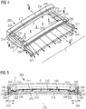
- Figures 3 , 4 , 5 and 6 show different views of the heatshield segment 200.
- Figure 3 shows a cross sectional view of the heatshield segment 200 as indicated by section line X-X in Figure 4.
- Figure 4 shows a isometric view of the heatshield segment 200.
- Figure 5 shows a sectional view of the heatshield element 200 indicated by Y-Y in Figure 4 .
- Figure 6 shows a view of heatshield segment from a different view point to that of Figure 4 , and which shows internal features which are hidden from view in Figure 4 .
- the heatshield apparatus 200 comprises a heatshield wall 210 which forms the main body of the heatshield.
- the hook 260 may extend from a leading edge wall 264 of the heatshield.
- the heatshield further comprises a first impingement plate section 212 and a second impingement plate section 214 which extends from the first impingement plate section 212.
- the first impingement plate section 212 is spaced apart from an impingement surface wall section 216 of the heatshield wall 210. Hence the impingement surface wall section 216 faces the first impingement plate section 212.
- the first impingement plate section 212 may be spaced apart from the impingement surface wall section 216 by a substantially constant distance to define a first fluid flow plenum 218 there between. That is to say, the first impingement plate section 212 may be spaced apart from and substantially parallel to the impingement surface wall section 216.
- a first aperture 220 is provided in the first impingement plate section 212.
- the aperture 220 is configured to permit fluid flow there through at a first angle relative to the impingement surface wall section 216.
- a plurality of apertures 220 are provided in the first impingement plate section 212. These may be provided in multiple rows and columns, although for clarity only a single column is shown in Figures 3 , 4, 5 .
- the second impingement plate section 214 is spaced apart from, and comprises a section at an angle to, the impingement surface wall section 216 to define a second fluid flow plenum 222 there between.
- a second aperture 224 is provided in the second impingement plate section 214.
- the second aperture 224 is configured to permit fluid flow there through at a second angle relevant to the impingement surface wall section 216.
- a plurality of apertures 224 may be provided, for example in a row as shown in Figures 4, 5 , 6 .
- the number, spacing and pattern of apertures 220, 224 may vary compared to that shown in the Figures.
- the first angle may be different to the second angle.
- the first angle may be substantially a right angle.
- the first apertures 220 may be configured to permit the fluid flow through the first impingement plate section 212 perpendicular to the impingement surface 216.
- the second aperture 224 may be configured to direct fluid flow in a direction away from the first fluid plenum 218.
- the first impingement plate section 212 and the second impingement plate section 214 may be formed integrally as an impingement plate 230. That is to say the first impingement plate section 212 and the second impingement plate section 214 may be formed integrally as a single impingement plate 230.
- the first fluid flow plenum 218 may be fluidly isolated from the second fluid flow plenum 222 by a plenum dividing wall 226.
- the plenum dividing wall 226 may be defined by a depression 232 in the impingement plate 230.
- the depression 232 may take the form of a bend or curve in the impingement plate, which extends towards and meets the impingement surface wall section 216 of the heatshield wall 210.
- a depression 232 at either end of the impingement plate 230 there is provided a depression 232 at either end of the impingement plate 230. That is to say, there is provided a second impingement plate section 214 along the ends of the impingement plate 230, of substantially similar design, although the apertures 224 in each second impingement plate section 214 are configured to direct fluid flow in a direction away from the other second impingement plate section 214.
- the impingement plate 230 is shown as having a pair of second impingement plate sections 214, it may also be considered to have a second impingement plate section 214 and a third impingement plate section 214' which are spaced apart from one another along the length of the impingement plate 230, albeit of similar design.
- impingement plate 230 may also be provided further depressions in the impingement plate 230 to create similar curved walls perforated with apertures for directing fluid flow at angles to the direction of flow through apertures 220.
- the impingement plate 230 may be fixed (i.e. joined) to the heatshield wall 210 by clips and/or brazing or any other suitable joining method. Alternatively the impingement plate may be formed integrally with the heatshield wall 210.
- the depression 232 which forms the plenum dividing wall 226 may be, as shown in the Figures, a curved section of the first impingement plate section 212 which extends to form the second impingement plate section 214. That is to say, the depression 232 defines a boundary between the first impingement plate section 212 and the second impingement plate section 214 as well as providing a wall between the first fluid flow plenum 218 and the second fluid flow plenum 220.
- the depression 232 defines the angle of the second impingement plate section 214 in which the second aperture(s) 224 are formed, and hence define the direction in which fluid passing through the apertures 224 will flow.
- fluid flow passing through the second apertures 224 in the second impingement plate section 214 will be at an angle to the surface of the heatshield wall 210.
- the heatshield wall 210 comprises a sidewall section 240 which extends along a side edge 242 of the impingement surface wall section 216. That is to say the heatshield element 220 is provided with sidewall sections 240 along the edges of the impingement surface wall section 216.
- the second impingement plate section 214 is located adjacent to the sidewall section 240 such that the second fluid flow plenum 222 is defined, at least in part, by regions of the sidewall section 240, the impingement surface wall section 216 and the second impingement plate section 214. As shown in the Figures, sidewall sections 240 are provided at both ends/edges of the heatshield element 200, with second impingement plate sections 214 located adjacent to both of the sidewall sections 240.
- the heatshield wall 210 further comprises an end wall section 250 which extends from the impingement surface wall section 216.
- the hook 262 extends from the end wall section 250.
- the first impingement plate section 212 is located, and may be sealed to, adjacent to the end wall section 250 such that the first fluid flow plenum 218 is defined, at least in part, by regions of the end wall section 250, the heatshield wall 210 and the first impingement plate section 212.
- the leading edge wall 264 may close the first and second plenums 28, 222 at one end, and the end wall section 250 may close the first and second plenums 28, 222 at their opposite end.
- the end wall section 250 extends away from the first and second fluid flow plenums 218, 222 and terminates at a trailing edge 252 of the heatshield.
- a first fluid passage 254 extends through the end wall section 250 towards the trailing edge 252. The first fluid passage 254 provides a flow path away from the first fluid flow plenum 218 through the end wall section 250.
- a second fluid passage 256 may extend through the end wall section 250 towards the trailing edge 254 to provide a flow path away from the second fluid flow plenum 222 through the end wall section 250.
- the first fluid passage 254 and second fluid passage 256 are provided at an angle relative to one another.
- first fluid flow passages 254 may be provided between the edges of the end wall section 250. Some of the first fluid passages 254 may be parallel to one another. At least one of the first fluid passages 254 may be at an angle to another first fluid passage 254.
- a plurality of second fluid passages 256 may also be provided, with at least one of the second fluid passages 256 being provided at an angle to another second fluid passage.
- the sidewall section 240 may be solid. That is to say the sidewall section 240 may not comprise any flow passages.
- a second fluid passage 256 extends out of the side edge 251 of the end wall section 250.
- the second fluid passages 256 may extend to the side edge 251 of the end wall section 250 and first fluid passages 254 extend to the trailing edge 252 of the end wall section 250.
- first fluid passages 254 may be provided, with all of the fluid passages in fluid communication with the first plenum 218 and second plenum 222 leading to the trailing edge 252 of the end wall section 250.
- the impingement plate sections 212, 214 may be provided as one integrally formed plate 230 which is fitted into an integrally formed main body of the heatshield element 200.
- the main body of the heatshield element may be cast (for example by investment casting), formed by an additive manufacturing or some other appropriate technique.
- the impingement plate sections 212, 214 may be formed from a sheet of suitable material and bent, stamped and/or pressed to create the depressions 232 as required to provide the necessary pattern for cooling.
- the apertures 220, 224 in the impingement plate sections may be laser drilled or machined by some other appropriate method in the required pattern. After the drilling process is complete the plate 230 is then fitted to the main body of the heatshield element 200.
- the heatshield element 200 may be provided as one of several heatshield elements which are assembled together to form part of the fluid duct.
- the heatshield elements 200 are assembled with the sidewalls 240 substantially abutting and located around the central axis 70 of the turbo machine.
- the heatshield wall 210 faces the impingement plate 212 on one side, and has a radially inner surface 270 which defines the fluid flow duct through the turbo machine.
- an air supply "D" is provided on the radially outer surface of the heatshield element 200 which causes fluid flow through the apertures 220, 224 as described above.
- the impingement surface wall section 216 is cooled by the fluid passing through the apertures 220, and the sidewalls 240 and regions close to the sidewalls 240 are cooled by the air passing through the apertures 224 in the second impingement plate section 214.
- the holes 224 may be directed to the surfaces of the main body of the heatshield 200 as required.
- air may be directed towards the inner surface of the sidewall section 240, the corner formed between the sidewalls 240 and the impingement surface wall section 216 (i.e. proximate to the side edge 242 of the impingement surface wall section 216). Having impinged on their respective surfaces, airflow then passes through the end wall section 250 to the trailing edge 254 or to the side edges 251 of the end wall section as described above. The air exits the heatshield and may pass along the surface of walls downstream of the heatshield element.
- a heatshield element 200 which comprises multiple cooling circuits formed by the plenums 218, 222 defined by the impingement plate depressions 232.
- the angled holes 224 of the second impingement plate section 214 formed by the depression 232 are advantageous because they may be directed as required to locations needing cooling, for example towards the corner of the side wall 240. Hence in use the holes 224 may direct cooling air to the sidewall 240 before re-cycling the cooling air through the end wall section 250 through passages 254, 256.
- the extra cooling provided by the angled holes means that fewer passages are required in the end wall section 250 compared to examples of the prior art, which saves machining processes and increases cooling efficiency. This enables a turbo machine comprising such a heatshield to operate at higher temperatures, which results in higher operating efficiency.
- cooling air available for cooling other features of the turbine, for example the rotor blades, stator vanes and rotor disc, as described in relation to Figure 2 .
- the impingement plate provides a simple cooling mechanism and, as it may be provided as a thin sheet with an array of holes, typically formed by laser cutting, it is relatively easy and cheap to both produce and modify.
- a heatshield apparatus not only provides a technical advantage, but also reduces manufacturing cost and risk.
Landscapes
- Engineering & Computer Science (AREA)
- Mechanical Engineering (AREA)
- General Engineering & Computer Science (AREA)
- Turbine Rotor Nozzle Sealing (AREA)
Priority Applications (1)
| Application Number | Priority Date | Filing Date | Title |
|---|---|---|---|
| EP17196321.8A EP3470631A1 (fr) | 2017-10-13 | 2017-10-13 | Appareil d'écran thermique |
Applications Claiming Priority (1)
| Application Number | Priority Date | Filing Date | Title |
|---|---|---|---|
| EP17196321.8A EP3470631A1 (fr) | 2017-10-13 | 2017-10-13 | Appareil d'écran thermique |
Publications (1)
| Publication Number | Publication Date |
|---|---|
| EP3470631A1 true EP3470631A1 (fr) | 2019-04-17 |
Family
ID=60119864
Family Applications (1)
| Application Number | Title | Priority Date | Filing Date |
|---|---|---|---|
| EP17196321.8A Withdrawn EP3470631A1 (fr) | 2017-10-13 | 2017-10-13 | Appareil d'écran thermique |
Country Status (1)
| Country | Link |
|---|---|
| EP (1) | EP3470631A1 (fr) |
Citations (4)
| Publication number | Priority date | Publication date | Assignee | Title |
|---|---|---|---|---|
| US4679981A (en) * | 1984-11-22 | 1987-07-14 | S.N.E.C.M.A. | Turbine ring for a gas turbine engine |
| US20040090013A1 (en) * | 2000-12-01 | 2004-05-13 | Lawer Steven D. | Seal segment for a turbine |
| US20120045319A1 (en) * | 2008-07-03 | 2012-02-23 | United Technologies Corporation | Impingement cooling for turbofan exhaust assembly |
| US20120121415A1 (en) * | 2010-11-17 | 2012-05-17 | General Electric Company | Turbomachine vane and method of cooling a turbomachine vane |
-
2017
- 2017-10-13 EP EP17196321.8A patent/EP3470631A1/fr not_active Withdrawn
Patent Citations (4)
| Publication number | Priority date | Publication date | Assignee | Title |
|---|---|---|---|---|
| US4679981A (en) * | 1984-11-22 | 1987-07-14 | S.N.E.C.M.A. | Turbine ring for a gas turbine engine |
| US20040090013A1 (en) * | 2000-12-01 | 2004-05-13 | Lawer Steven D. | Seal segment for a turbine |
| US20120045319A1 (en) * | 2008-07-03 | 2012-02-23 | United Technologies Corporation | Impingement cooling for turbofan exhaust assembly |
| US20120121415A1 (en) * | 2010-11-17 | 2012-05-17 | General Electric Company | Turbomachine vane and method of cooling a turbomachine vane |
Similar Documents
| Publication | Publication Date | Title |
|---|---|---|
| JP6266231B2 (ja) | タービンロータブレード先端における冷却構造 | |
| US20170248155A1 (en) | Centrifugal compressor diffuser passage boundary layer control | |
| EP3460190A1 (fr) | Structures d'amélioration de transfert de chaleur sur des nervures en ligne d'une cavité de surface portante d'une turbine à gaz | |
| EP3485147B1 (fr) | Refroidissement par impact d'une plate-forme d'aube | |
| CN108868897B (zh) | 涡轮发动机翼型件的插入件 | |
| US20180320530A1 (en) | Airfoil with tip rail cooling | |
| US11624286B2 (en) | Insert for re-using impingement air in an airfoil, airfoil comprising an impingement insert, turbomachine component and a gas turbine having the same | |
| US11927110B2 (en) | Component for a turbine engine with a cooling hole | |
| US20170298743A1 (en) | Component for a turbine engine with a film-hole | |
| JP2015092076A (ja) | タービンアセンブリに冷却を提供するための方法およびシステム | |
| WO2009107312A1 (fr) | Turbine à gaz, disque et procédé de formation de passage radial de disque | |
| CN108026772A (zh) | 用于燃气轮机的装置 | |
| JP2016510854A (ja) | ガスタービンの耐久性のためのホットストリーク整列方法 | |
| US20190145267A1 (en) | Engine component with non-diffusing section | |
| CN107084007A (zh) | 具有横贯孔的翼型件 | |
| JP2017075598A (ja) | 冷却流路冷却材排出プレナムを有するタービンノズル | |
| US10760431B2 (en) | Component for a turbine engine with a cooling hole | |
| KR20220040981A (ko) | 가스 터빈 블레이드의 스퀄러 팁의 냉각 기술 | |
| US11549377B2 (en) | Airfoil with cooling hole | |
| EP3647544B1 (fr) | Profil d'aube statorique refroidie d'une turbine à gaz | |
| JP2007032569A (ja) | 冷却式シュラウド組立体及びシュラウドの冷却方法 | |
| GB2054046A (en) | Cooling turbine rotors | |
| US20180230812A1 (en) | Film hole arrangement for a turbine engine | |
| CN107061015A (zh) | 具有冷却流体路径的燃气涡轮发动机 | |
| JP6961340B2 (ja) | 回転機械 |
Legal Events
| Date | Code | Title | Description |
|---|---|---|---|
| PUAI | Public reference made under article 153(3) epc to a published international application that has entered the european phase |
Free format text: ORIGINAL CODE: 0009012 |
|
| STAA | Information on the status of an ep patent application or granted ep patent |
Free format text: STATUS: THE APPLICATION HAS BEEN PUBLISHED |
|
| AK | Designated contracting states |
Kind code of ref document: A1 Designated state(s): AL AT BE BG CH CY CZ DE DK EE ES FI FR GB GR HR HU IE IS IT LI LT LU LV MC MK MT NL NO PL PT RO RS SE SI SK SM TR |
|
| AX | Request for extension of the european patent |
Extension state: BA ME |
|
| STAA | Information on the status of an ep patent application or granted ep patent |
Free format text: STATUS: THE APPLICATION IS DEEMED TO BE WITHDRAWN |
|
| 18D | Application deemed to be withdrawn |
Effective date: 20191018 |