EP3470670B1 - System und verfahren zum betreiben von windturbinen zur vermeidung von strömungsabrissen während der leistungsherabsetzung - Google Patents
System und verfahren zum betreiben von windturbinen zur vermeidung von strömungsabrissen während der leistungsherabsetzung Download PDFInfo
- Publication number
- EP3470670B1 EP3470670B1 EP18198193.7A EP18198193A EP3470670B1 EP 3470670 B1 EP3470670 B1 EP 3470670B1 EP 18198193 A EP18198193 A EP 18198193A EP 3470670 B1 EP3470670 B1 EP 3470670B1
- Authority
- EP
- European Patent Office
- Prior art keywords
- wind turbine
- condition
- pitch setting
- derating
- operating
- Prior art date
- Legal status (The legal status is an assumption and is not a legal conclusion. Google has not performed a legal analysis and makes no representation as to the accuracy of the status listed.)
- Active
Links
Images

Classifications
-
- F—MECHANICAL ENGINEERING; LIGHTING; HEATING; WEAPONS; BLASTING
- F03—MACHINES OR ENGINES FOR LIQUIDS; WIND, SPRING, OR WEIGHT MOTORS; PRODUCING MECHANICAL POWER OR A REACTIVE PROPULSIVE THRUST, NOT OTHERWISE PROVIDED FOR
- F03D—WIND MOTORS
- F03D7/00—Controlling wind motors
- F03D7/02—Controlling wind motors the wind motors having rotation axis substantially parallel to the air flow entering the rotor
- F03D7/0256—Stall control
-
- F—MECHANICAL ENGINEERING; LIGHTING; HEATING; WEAPONS; BLASTING
- F03—MACHINES OR ENGINES FOR LIQUIDS; WIND, SPRING, OR WEIGHT MOTORS; PRODUCING MECHANICAL POWER OR A REACTIVE PROPULSIVE THRUST, NOT OTHERWISE PROVIDED FOR
- F03D—WIND MOTORS
- F03D7/00—Controlling wind motors
- F03D7/02—Controlling wind motors the wind motors having rotation axis substantially parallel to the air flow entering the rotor
- F03D7/022—Adjusting aerodynamic properties of the blades
- F03D7/0224—Adjusting blade pitch
-
- F—MECHANICAL ENGINEERING; LIGHTING; HEATING; WEAPONS; BLASTING
- F03—MACHINES OR ENGINES FOR LIQUIDS; WIND, SPRING, OR WEIGHT MOTORS; PRODUCING MECHANICAL POWER OR A REACTIVE PROPULSIVE THRUST, NOT OTHERWISE PROVIDED FOR
- F03D—WIND MOTORS
- F03D7/00—Controlling wind motors
- F03D7/02—Controlling wind motors the wind motors having rotation axis substantially parallel to the air flow entering the rotor
- F03D7/028—Controlling wind motors the wind motors having rotation axis substantially parallel to the air flow entering the rotor controlling wind motor output power
-
- F—MECHANICAL ENGINEERING; LIGHTING; HEATING; WEAPONS; BLASTING
- F03—MACHINES OR ENGINES FOR LIQUIDS; WIND, SPRING, OR WEIGHT MOTORS; PRODUCING MECHANICAL POWER OR A REACTIVE PROPULSIVE THRUST, NOT OTHERWISE PROVIDED FOR
- F03D—WIND MOTORS
- F03D7/00—Controlling wind motors
- F03D7/02—Controlling wind motors the wind motors having rotation axis substantially parallel to the air flow entering the rotor
- F03D7/04—Automatic control; Regulation
- F03D7/042—Automatic control; Regulation by means of an electrical or electronic controller
- F03D7/047—Automatic control; Regulation by means of an electrical or electronic controller characterised by the controller architecture, e.g. multiple processors or data communications
-
- G—PHYSICS
- G05—CONTROLLING; REGULATING
- G05B—CONTROL OR REGULATING SYSTEMS IN GENERAL; FUNCTIONAL ELEMENTS OF SUCH SYSTEMS; MONITORING OR TESTING ARRANGEMENTS FOR SUCH SYSTEMS OR ELEMENTS
- G05B19/00—Program-control systems
- G05B19/02—Program-control systems electric
- G05B19/04—Program control other than numerical control, i.e. in sequence controllers or logic controllers
- G05B19/042—Program control other than numerical control, i.e. in sequence controllers or logic controllers using digital processors
-
- F—MECHANICAL ENGINEERING; LIGHTING; HEATING; WEAPONS; BLASTING
- F03—MACHINES OR ENGINES FOR LIQUIDS; WIND, SPRING, OR WEIGHT MOTORS; PRODUCING MECHANICAL POWER OR A REACTIVE PROPULSIVE THRUST, NOT OTHERWISE PROVIDED FOR
- F03D—WIND MOTORS
- F03D1/00—Wind motors with rotation axis substantially parallel to the air flow entering the rotor
- F03D1/06—Rotors
-
- F—MECHANICAL ENGINEERING; LIGHTING; HEATING; WEAPONS; BLASTING
- F05—INDEXING SCHEMES RELATING TO ENGINES OR PUMPS IN VARIOUS SUBCLASSES OF CLASSES F01-F04
- F05B—INDEXING SCHEME RELATING TO WIND, SPRING, WEIGHT, INERTIA OR LIKE MOTORS, TO MACHINES OR ENGINES FOR LIQUIDS COVERED BY SUBCLASSES F03B, F03D AND F03G
- F05B2270/00—Control
- F05B2270/30—Control parameters, e.g. input parameters
- F05B2270/323—Air humidity
-
- F—MECHANICAL ENGINEERING; LIGHTING; HEATING; WEAPONS; BLASTING
- F05—INDEXING SCHEMES RELATING TO ENGINES OR PUMPS IN VARIOUS SUBCLASSES OF CLASSES F01-F04
- F05B—INDEXING SCHEME RELATING TO WIND, SPRING, WEIGHT, INERTIA OR LIKE MOTORS, TO MACHINES OR ENGINES FOR LIQUIDS COVERED BY SUBCLASSES F03B, F03D AND F03G
- F05B2270/00—Control
- F05B2270/30—Control parameters, e.g. input parameters
- F05B2270/324—Air pressure
-
- F—MECHANICAL ENGINEERING; LIGHTING; HEATING; WEAPONS; BLASTING
- F05—INDEXING SCHEMES RELATING TO ENGINES OR PUMPS IN VARIOUS SUBCLASSES OF CLASSES F01-F04
- F05B—INDEXING SCHEME RELATING TO WIND, SPRING, WEIGHT, INERTIA OR LIKE MOTORS, TO MACHINES OR ENGINES FOR LIQUIDS COVERED BY SUBCLASSES F03B, F03D AND F03G
- F05B2270/00—Control
- F05B2270/30—Control parameters, e.g. input parameters
- F05B2270/325—Air temperature
-
- G—PHYSICS
- G05—CONTROLLING; REGULATING
- G05B—CONTROL OR REGULATING SYSTEMS IN GENERAL; FUNCTIONAL ELEMENTS OF SUCH SYSTEMS; MONITORING OR TESTING ARRANGEMENTS FOR SUCH SYSTEMS OR ELEMENTS
- G05B2219/00—Program-control systems
- G05B2219/20—Pc systems
- G05B2219/26—Pc applications
- G05B2219/2619—Wind turbines
-
- Y—GENERAL TAGGING OF NEW TECHNOLOGICAL DEVELOPMENTS; GENERAL TAGGING OF CROSS-SECTIONAL TECHNOLOGIES SPANNING OVER SEVERAL SECTIONS OF THE IPC; TECHNICAL SUBJECTS COVERED BY FORMER USPC CROSS-REFERENCE ART COLLECTIONS [XRACs] AND DIGESTS
- Y02—TECHNOLOGIES OR APPLICATIONS FOR MITIGATION OR ADAPTATION AGAINST CLIMATE CHANGE
- Y02E—REDUCTION OF GREENHOUSE GAS [GHG] EMISSIONS, RELATED TO ENERGY GENERATION, TRANSMISSION OR DISTRIBUTION
- Y02E10/00—Energy generation through renewable energy sources
- Y02E10/70—Wind energy
- Y02E10/72—Wind turbines with rotation axis in wind direction
Definitions
- the present invention relates generally to wind turbines, and more particularly, to systems and methods for operating wind turbines to avoid stall during derating.
- Wind power is considered one of the cleanest, most environmentally friendly energy sources presently available, and wind turbines have gained increased attention in this regard.
- a modern wind turbine typically includes a tower, a generator, a gearbox, a nacelle, and a rotor.
- the rotor typically includes a rotatable hub having one or more rotor blades attached thereto.
- a pitch bearing is typically configured operably between the hub and the rotor blade to allow for rotation about a pitch axis.
- the rotor blades capture kinetic energy of wind using known airfoil principles.
- the rotor blades transmit the kinetic energy in the form of rotational energy so as to turn a shaft coupling the rotor blades to a gearbox, or if a gearbox is not used, directly to the generator.
- the generator then converts the mechanical energy to electrical energy that may be deployed to a utility grid.
- a power output of the generator increases with wind speed until the wind speed reaches a rated wind speed for the turbine.
- the generator operates at a rated power.
- the rated power is an output power at which the generator can operate with a level of fatigue or extreme load to turbine components that is predetermined to be acceptable.
- the wind turbine may implement a control action, such as shutting down or de-rating the wind turbine in order to protect wind turbine components from damage.
- US 2013/010 8443 A1 relates to methods for operating a wind turbine.
- US 2015/015 9625 A1 relates to a method for controlling a wind turbine system. Ameet Deshpande et al., 2012 IEEE Power and Energy Society General Meeting , relates to wind turbine controller design considerations for improved wind farm level curtailment tracking.
- Additional instances may also exist in which a wind turbine may need to be de-rated.
- Such derating is typically achieved by reducing either the torque or speed set points of the wind turbine. For example, if a load monitoring system of the turbine is inoperable (e.g. due to installation, maintenance, repair, and/or replacement), the wind turbine should be de-rated to mitigate loads. Though derating the speed may mitigate loads, such derating may also lead to stall especially in low air density conditions. Accordingly, systems and methods for operating wind turbines to avoid stall during derating would be desired in the art.
- the operating condition(s) of the wind turbine may include a sensor system condition.
- the method may further include modifying the initial pitch setting to the updated pitch setting when the sensor system condition of the wind turbine indicates a failure.
- the step of derating the wind turbine may include reducing a torque set point of the wind turbine.
- the step of modifying the initial pitch setting to the updated pitch setting may include pitching the one or more rotor blades towards feather.
- the method may include determining the updated pitch setting based on at least one of power or thrust of the wind turbine. In further embodiments, the method may also include modifying the initial pitch setting to the updated pitch setting via at least one of a table or a function.
- the present invention is directed to a method for operating a wind turbine to avoid stall during derating thereof.
- the present invention is also directed to a system for operating a wind turbine to avoid stall during derating thereof according to the independent system claim.
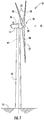
- FIG. 1 illustrates a perspective view of one embodiment of a wind turbine 10 according to the present disclosure.
- the wind turbine 10 generally includes a tower 12 extending from a support surface 14, a nacelle 16 mounted on the tower 12, and a rotor 18 coupled to the nacelle 16.
- the rotor 18 includes a rotatable hub 20 and at least one rotor blade 22 coupled to and extending outwardly from the hub 20.
- the rotor 18 includes three rotor blades 22.
- the rotor 18 may include more or less than three rotor blades 22.
- Each rotor blade 22 may be spaced about the hub 20 to facilitate rotating the rotor 18 to enable kinetic energy to be transferred from the wind into usable mechanical energy, and subsequently, electrical energy.
- the hub 20 may be rotatably coupled to an electric generator 24 ( FIG. 2 ) positioned within the nacelle 16 to permit electrical energy to be produced.
- the wind turbine 10 may also include a wind turbine controller 26 centralized within the nacelle 16.
- the turbine controller 26 is located in the top box cabinet 48.
- the controller 26 may be located within any other component of the wind turbine 10 or at a location outside the wind turbine 10.
- the controller 26 may be communicatively coupled to any number of the components of the wind turbine 10 in order to control the operation of such components and/or implement a correction action.
- the controller 26 may include a computer or other suitable processing unit.
- the controller 26 may include suitable computer-readable instructions that, when implemented, configure the controller 26 to perform various different functions, such as receiving, transmitting and/or executing wind turbine control signals.
- the controller 26 may generally be configured to control the various operating modes (e.g., start-up or shut-down sequences), de-rating or up-rating the wind turbine, and/or individual components of the wind turbine 10.
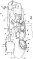
- a generator 24 may be disposed within the nacelle 16.
- the generator 24 may be coupled to the rotor 18 for producing electrical power from the rotational energy generated by the rotor 18.
- the rotor 18 may include a rotor shaft 34 coupled to the hub 20 for rotation therewith.
- the rotor shaft 34 may, in turn, be rotatably coupled to a generator shaft 36 of the generator 24 through a gearbox 38.
- the rotor shaft 34 may provide a low speed, high torque input to the gearbox 38 in response to rotation of the rotor blades 22 and the hub 20.
- the gearbox 38 may then be configured to convert the low speed, high torque input to a high speed, low torque output to drive the generator shaft 36 and, thus, the generator 24.
- each rotor blade 22 may also include a pitch adjustment mechanism 32 configured to rotate each rotor blade 22 about its pitch axis 28.
- each pitch adjustment mechanism 32 may include a pitch drive motor 40 (e.g., any suitable electric, hydraulic, or pneumatic motor), a pitch drive gearbox 42, and a pitch drive pinion 44.
- the pitch drive motor 40 may be coupled to the pitch drive gearbox 42 so that the pitch drive motor 40 imparts mechanical force to the pitch drive gearbox 42.
- the pitch drive gearbox 42 may be coupled to the pitch drive pinion 44 for rotation therewith.
- the pitch drive pinion 44 may, in turn, be in rotational engagement with a pitch bearing 46 coupled between the hub 20 and a corresponding rotor blade 22 such that rotation of the pitch drive pinion 44 causes rotation of the pitch bearing 46.
- rotation of the pitch drive motor 40 drives the pitch drive gearbox 42 and the pitch drive pinion 44, thereby rotating the pitch bearing 46 and the rotor blade 22 about the pitch axis 28.
- the wind turbine 10 may include one or more yaw drive mechanisms 66 communicatively coupled to the controller 26, with each yaw drive mechanism(s) 66 being configured to change the angle of the nacelle 16 relative to the wind direction 30 (e.g., by engaging a yaw bearing 68 of the wind turbine 10 so as to rotate the nacelle about a yaw axis 67 ( FIG. 1 )).
- the wind turbine 10 may also include a sensor system 64 having one or more sensors 48, 50, 52, 54 for measuring various operating, wind, and/or environmental parameters of the wind turbine 10.
- a sensor(s) 48 may be located on the hub 20 so as to measure hub loads of the wind turbine 10.
- a sensor(s) 50 may be located on one or more of the rotor blades 22 so as to measure loads thereof.
- a sensor(s) 54 may be located on the tower 12 of the wind turbine 10 to measure loads thereof.
- the wind turbine 10 may include one or more wind or environmental sensors 52 for measuring various wind and/or environmental parameters of the wind turbine 10.
- such parameter(s) may include wind gusts, wind speed, wind direction, wind acceleration, wind turbulence, wind shear, wind veer, wake, or similar, as well as air density, air moisture, humidity, pressure, temperature, or any other environmental condition.
- the sensors 48, 50, 52, 54 may be any other suitable sensors capable of measuring operating and/or wind parameters of the wind turbine 10.
- the sensors may be accelerometers, pressure sensors, angle of attack sensors, vibration sensors, MIMU sensors, camera systems, fiber optic systems, anemometers, wind vanes, Sonic Detection and Ranging (SODAR) sensors, infra lasers, radiometers, pitot tubes, rawinsondes, other optical sensors, and/or any other suitable sensors.
- SODAR Sonic Detection and Ranging
- the various sensors of the wind turbine may be configured to provide a direct measurement of the parameters being monitored or an indirect measurement of such parameters.
- the sensors 48, 50, 52, 54 may, for example, be used to generate signals relating to the parameter being monitored, which can then be utilized by the controller 26 to determine the actual condition.
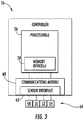
- the controller 26 may include one or more processor(s) 56 and associated memory device(s) 58 configured to perform a variety of computer-implemented functions (e.g., performing the methods, steps, calculations and the like and storing relevant data as disclosed herein). Additionally, the controller 26 may also include a communications module 60 to facilitate communications between the controller 26 and the various components of the wind turbine 10. Further, the communications module 60 may include a sensor interface 62 (e.g., one or more analog-to-digital converters) to permit signals transmitted from the sensors 48, 50, 52, 54 to be converted into signals that can be understood and processed by the processors 56.
- a sensor interface 62 e.g., one or more analog-to-digital converters
- the sensors 48, 50, 52, 54 may be communicatively coupled to the communications module 60 using any suitable means.
- the sensors 48, 50, 52, 54 are coupled to the sensor interface 62 via a wired connection.
- the sensors 48, 50, 52, 54 may be coupled to the sensor interface 62 via a wireless connection, such as by using any suitable wireless communications protocol known in the art.
- the processor 56 may be configured to receive one or more signals from the sensors 48, 50, 52, 54.
- Such memory device(s) 58 may generally be configured to store suitable computer-readable instructions that, when implemented by the processor(s) 58, configure the controller 26 to perform various functions including, but not limited to, estimating one or more wind parameters of the wind turbine 10 based on the plurality of operating data, transmitting suitable control signals to implement control actions in response to the detection of transient wind conditions and various other suitable computer-implemented functions.
- the method 100 includes identifying at least one condition of the wind turbine 10 that is indicative of stall.
- the at least one condition comprises at least one environmental condition, the at least one environmental condition comprising air density.
- the condition(s) of the wind turbine 10 may include environmental and operating conditions thereof. Further, as mentioned, such conditions may be monitored using the sensors 48, 50, 52, 54.
- the environmental condition(s) described herein include(s) air density, and may further include air moisture, humidity, pressure, temperature, or any other environmental condition.
- the operating condition(s) of the wind turbine 10 may include any suitable operational parameters thereof. In one embodiment, for example, the operating condition may correspond to a sensor system 64 condition.
- the method 100 also includes derating the wind turbine 10 so as to permit the loads acting on or more of the wind turbine components to be reduced or otherwise controlled.
- derating the wind turbine 10 comprises reducing a speed set point of the wind turbine 10.
- Derating may further include a combination of speed de-rating and torque de-rating.
- the wind turbine 10 may be temporarily de-rated by modifying the torque demand on the generator 24.
- the torque demand may be modified using any suitable method, process, structure and/or means known in the art.
- the torque demand on the generator 24 may be controlled using the controller 26 by transmitting a suitable control signal/command to the generator 24 in order to modulate the magnetic flux produced within the generator 24.
- the wind turbine 10 may also be temporarily de-rated by yawing the nacelle 16 to change the angle of the nacelle 16 relative to the direction of the wind 30.
- the controller 26 may be configured to actuate one or more mechanical brake(s) or activate an airflow modifying element on a rotor blade in order to reduce the rotational speed and/or load of the rotor blades 14, thereby reducing component loading.
- the controller 26 may be configured to perform any appropriate control action known in the art. Further, the controller 26 may implement a combination of two or more control actions.
- the method 100 includes modifying the initial pitch setting to an updated pitch setting when the monitored condition(s) is identified.
- the updated pitch settings may change with power, estimated thrust, and/or estimated loads.
- the sensors 48, 50, 52, 54 may determine that certain cold weather conditions exist or a fault message from the sensor system 64 may be received, both of which may present situations prone to stall.
- the method 100 may include modifying the initial pitch setting to the updated pitch setting when the air density is below a predetermined threshold.
- the method 100 may include modifying the initial pitch setting to the updated pitch setting when the ambient temperature is low, e.g. from about -30°C to about 15°C.
- the controller 26 is configured to modify the pitch angle of one or more of the rotor blades 22 from a power position towards a feather position.
- feathering the rotor blades 22 generally encompasses increasing the pitch angles thereof by rotating the blades 22 to be closer to parallel to the airflow.
- a fully feathered rotor blade includes pitch angles close to about 90 degrees with respect to the wind 30.
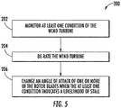
- the method 200 includes monitoring at least one condition of the wind turbine.
- the method 200 includes derating the wind turbine 10, i.e. using any of the suitable derating methods described herein.
- the method 200 also includes changing an angle of attack of one or more of the rotor blades 22 when the at least one condition indicates a likelihood of stall.
- the angle of attack of the rotor blades 22 may be changed by pitching the rotor blades 22 towards a feather position during normal operation.
- an advantage of the present invention is that the system and method may be implemented using existing components of the wind turbine 10. As such, a user is not required to purchase, install, and maintain new equipment. Further, the controller 26 may be integrated with a broader control system, such as, but not limiting of, a wind turbine control system, a plant control system, a remote monitoring system, or combinations thereof.
Landscapes
- Engineering & Computer Science (AREA)
- Mechanical Engineering (AREA)
- Sustainable Development (AREA)
- Sustainable Energy (AREA)
- Chemical & Material Sciences (AREA)
- Combustion & Propulsion (AREA)
- Life Sciences & Earth Sciences (AREA)
- General Engineering & Computer Science (AREA)
- Physics & Mathematics (AREA)
- Fluid Mechanics (AREA)
- General Physics & Mathematics (AREA)
- Automation & Control Theory (AREA)
- Wind Motors (AREA)
Claims (14)
- Verfahren (100) zum Betreiben einer Windturbine (10) zum Vermeiden von Strömungsabrissen während des Deratings derselben, wobei das Verfahren (100) umfasst:Bereitstellen (102) einer anfänglichen Neigungseinstellung für ein oder mehrere Rotorblätter (22) der Windturbine (10);Betreiben (104) der Windturbine (10) basierend auf einer Nennleistungskurve, wobei das eine oder die mehreren Rotorblätter (22) bei der anfänglichen Neigungseinstellung fixiert sind;Identifizieren (106) mindestens eines Zustands der Windturbine (10), der einen Strömungsabriss anzeigt, wobei der mindestens eine Zustand mindestens einen Umgebungszustand umfasst, wobei der mindestens eine Umgebungszustand Luftdichte umfasst;Derating (108) der Windturbine (10), umfassend das Reduzieren eines Drehzahlsollwerts der Windturbine (10); undModifizieren (110) der anfänglichen Neigungseinstellung auf eine aktualisierte Neigungseinstellung, wenn der mindestens eine Zustand identifiziert wird, sodass während des Deratings ein Anstellwinkel des einen oder der mehreren Rotorblätter niedriger gehalten wird als ein Anstellwinkel beim Strömungsabriss.
- Verfahren (100) nach Anspruch 1, wobei der mindestens eine Zustand ferner einen Betriebszustand der Windturbine (10) umfasst.
- Verfahren (100) nach einem der vorstehenden Ansprüche, wobei der mindestens eine Umgebungszustand mindestens eines von Luftfeuchtigkeit, Feuchtigkeit, Druck oder Temperatur umfasst.
- Verfahren (100) nach einem der vorstehenden Ansprüche, ferner umfassend das Modifizieren der anfänglichen Neigungseinstellung auf die aktualisierte Neigungseinstellung, wenn die Luftdichte unterhalb eines vorbestimmten Schwellenwerts liegt.
- Verfahren (100) nach einem der vorstehenden Ansprüche, ferner umfassend das Überwachen des mindestens einen Zustands der Windturbine (10) über einen oder mehrere Sensoren.
- Verfahren (100) nach einem der Ansprüche 3-5, wenn abhängig von Anspruch 2, wobei der Betriebszustand der Windturbine (10) einen Sensorsystemzustand umfasst.
- Verfahren (100) nach Anspruch 6, ferner umfassend das Modifizieren der anfänglichen Neigungseinstellung auf die aktualisierte Neigungseinstellung, wenn der Sensorsystemzustand der Windturbine (10) einen Ausfall anzeigt.
- Verfahren (100) nach einem der vorstehenden Ansprüche, wobei das Modifizieren der anfänglichen Neigungseinstellung auf die aktualisierte Neigungseinstellung ferner das Neigen des einen oder der mehreren Rotorblätter (22) in Richtung Feder umfasst.
- Verfahren (100) nach einem der vorstehenden Ansprüche, ferner umfassend das Bestimmen der aktualisierten Neigungseinstellung basierend auf mindestens einem von Leistung oder Schub der Windturbine (10).
- Verfahren (100) nach einem der vorstehenden Ansprüche, ferner umfassend das Modifizieren der anfänglichen Neigungseinstellung auf die aktualisierte Neigungseinstellung über mindestens eines von einer Tabelle oder einer Funktion.
- System zum Betreiben einer Windturbine (10) zum Vermeiden von Strömungsabrissen während des Deratings derselben, wobei das System umfasst:einen oder mehrere Sensoren, die zum Identifizieren eines Zustands der Windturbine (10) konfiguriert sind, der einen Strömungsabriss anzeigt, wobei der mindestens eine Zustand mindestens einen Umgebungszustand umfasst, wobei der mindestens eine Umgebungszustand Luftdichte umfasst;eine Steuerung (56), die mit dem einen oder den mehreren Sensoren kommunikativ gekoppelt ist, wobei die Steuerung (56) zum Durchführen von Vorgängen konfiguriert ist, wobei die Vorgänge umfassen:Bereitstellen einer anfänglichen Neigungseinstellung für ein oder mehrere Rotorblätter (22) der Windturbine (10);Betreiben der Windturbine (10) basierend auf einer Nennleistungskurve, wobei das eine oder die mehreren Rotorblätter (22) bei der anfänglichen Neigungseinstellung fixiert sind;Derating der Windturbine (10), umfassend das Reduzieren eines Drehzahlsollwerts der Windturbine (10); undModifizieren der anfänglichen Neigungseinstellung auf eine aktualisierte Neigungseinstellung, wenn der mindestens eine Zustand identifiziert wird, sodass während des Deratings ein Anstellwinkel des einen oder der mehreren Rotorblätter niedriger gehalten wird als ein Anstellwinkel beim Strömungsabriss.
- System nach Anspruch 11, wobei der mindestens eine Zustand ferner einen Betriebszustand der Windturbine (10) umfasst.
- System nach Anspruch 11 oder 12, wobei der mindestens eine Umgebungszustand ferner mindestens eines von Luftfeuchtigkeit, Feuchtigkeit, Druck oder Temperatur umfasst und wobei der Betriebszustand der Windturbine (10) einen Sensorsystemzustand umfasst.
- System nach einem der Ansprüche 11 bis 13, wobei die Vorgänge ferner das Modifizieren der anfänglichen Neigungseinstellung auf die aktualisierte Neigungseinstellung, wenn die Luftdichte unterhalb eines vorbestimmten Schwellenwerts liegt, und/oder das Modifizieren der anfänglichen Neigungseinstellung auf die aktualisierte Neigungseinstellung, wenn ein Sensorsystemzustand der Windturbine (10) einen Ausfall anzeigt, umfassen.
Applications Claiming Priority (1)
| Application Number | Priority Date | Filing Date | Title |
|---|---|---|---|
| US15/728,534 US10669988B2 (en) | 2017-10-10 | 2017-10-10 | System and method for operating wind turbines to avoid stall during derating |
Publications (2)
| Publication Number | Publication Date |
|---|---|
| EP3470670A1 EP3470670A1 (de) | 2019-04-17 |
| EP3470670B1 true EP3470670B1 (de) | 2022-01-05 |
Family
ID=63722216
Family Applications (1)
| Application Number | Title | Priority Date | Filing Date |
|---|---|---|---|
| EP18198193.7A Active EP3470670B1 (de) | 2017-10-10 | 2018-10-02 | System und verfahren zum betreiben von windturbinen zur vermeidung von strömungsabrissen während der leistungsherabsetzung |
Country Status (4)
| Country | Link |
|---|---|
| US (1) | US10669988B2 (de) |
| EP (1) | EP3470670B1 (de) |
| DK (1) | DK3470670T3 (de) |
| ES (1) | ES2909373T3 (de) |
Families Citing this family (6)
| Publication number | Priority date | Publication date | Assignee | Title |
|---|---|---|---|---|
| CN113494428B (zh) * | 2020-03-20 | 2022-11-22 | 新疆金风科技股份有限公司 | 风力发电机组的故障检测方法和装置 |
| EP4165304B1 (de) | 2020-06-15 | 2025-07-30 | Vestas Wind Systems A/S | Verfahren zur messung des strömungsabrisszustands eines windturbinenrotors |
| CN112283027B (zh) * | 2020-11-19 | 2022-05-31 | 上海电气风电集团股份有限公司 | 风电机组变桨系统后备电源的选型方法及系统、控制方法及系统及计算机可读存储介质 |
| CN114607555B (zh) * | 2020-12-03 | 2024-10-18 | 金风科技股份有限公司 | 用于风力发电机组的控制方法及装置 |
| CN114607556B (zh) * | 2020-12-09 | 2024-09-24 | 金风科技股份有限公司 | 用于风力发电机组的控制方法及装置 |
| CN115143046B (zh) * | 2021-03-30 | 2025-08-12 | 金风科技股份有限公司 | 风力发电机组的叶片失速识别方法和设备 |
Citations (4)
| Publication number | Priority date | Publication date | Assignee | Title |
|---|---|---|---|---|
| US20130108443A1 (en) | 2006-10-23 | 2013-05-02 | General Electric Company | Methods for operating a wind turbine |
| US20130214535A1 (en) | 2010-08-23 | 2013-08-22 | Per Brath | Method of operating a wind turbine and wind turbine |
| US20150159625A1 (en) | 2013-12-11 | 2015-06-11 | General Electric Company | System and method for controlling a wind turbine system |
| US20170058871A1 (en) * | 2015-08-27 | 2017-03-02 | General Electric Company | System and method for mitigating ice throw from a wind turbine rotor blade |
Family Cites Families (7)
| Publication number | Priority date | Publication date | Assignee | Title |
|---|---|---|---|---|
| EP2180183A1 (de) * | 2008-10-23 | 2010-04-28 | Siemens Aktiengesellschaft | Strömungsabrissdetektion unter Verwendung von Drucksensoren |
| US20130259682A1 (en) * | 2012-03-27 | 2013-10-03 | General Electric Company | Method of rotor-stall prevention in wind turbines |
| EP2679808A1 (de) * | 2012-06-28 | 2014-01-01 | Siemens Aktiengesellschaft | Strömungsabrisserkennung von Windturbinenschaufeln |
| WO2014176525A1 (en) * | 2013-04-25 | 2014-10-30 | Kyrazis Demos T | Predictive blade adjustment |
| GB2514845B (en) * | 2013-06-07 | 2019-11-13 | Equinor Energy As | Wind turbine control |
| DK2857677T3 (en) * | 2013-10-01 | 2018-07-02 | Siemens Ag | Adjusting a rotor blade pitch angle |
| CN107709764B (zh) * | 2015-06-30 | 2019-10-18 | 维斯塔斯风力系统集团公司 | 用于生成风力涡轮机控制安排的方法和系统 |
-
2017
- 2017-10-10 US US15/728,534 patent/US10669988B2/en active Active
-
2018
- 2018-10-02 EP EP18198193.7A patent/EP3470670B1/de active Active
- 2018-10-02 ES ES18198193T patent/ES2909373T3/es active Active
- 2018-10-02 DK DK18198193.7T patent/DK3470670T3/da active
Patent Citations (4)
| Publication number | Priority date | Publication date | Assignee | Title |
|---|---|---|---|---|
| US20130108443A1 (en) | 2006-10-23 | 2013-05-02 | General Electric Company | Methods for operating a wind turbine |
| US20130214535A1 (en) | 2010-08-23 | 2013-08-22 | Per Brath | Method of operating a wind turbine and wind turbine |
| US20150159625A1 (en) | 2013-12-11 | 2015-06-11 | General Electric Company | System and method for controlling a wind turbine system |
| US20170058871A1 (en) * | 2015-08-27 | 2017-03-02 | General Electric Company | System and method for mitigating ice throw from a wind turbine rotor blade |
Non-Patent Citations (1)
| Title |
|---|
| AMEET S. DESHPANDE ; RHONDA R. PETERS: "Wind turbine controller design considerations for improved wind farm level curtailment tracking", 2012 IEEE POWER AND ENERGY SOCIETY GENERAL MEETING, 22 July 2012 (2012-07-22), pages 1 - 6, XP032393927 |
Also Published As
| Publication number | Publication date |
|---|---|
| EP3470670A1 (de) | 2019-04-17 |
| US20190107102A1 (en) | 2019-04-11 |
| ES2909373T3 (es) | 2022-05-06 |
| DK3470670T3 (da) | 2022-04-11 |
| US10669988B2 (en) | 2020-06-02 |
Similar Documents
| Publication | Publication Date | Title |
|---|---|---|
| EP2840258B1 (de) | System und Verfahren zur Vermeidung einer übermassige Belastung einer Windkraftenergieanlage | |
| EP3470670B1 (de) | System und verfahren zum betreiben von windturbinen zur vermeidung von strömungsabrissen während der leistungsherabsetzung | |
| EP2860394B1 (de) | System und Verfahren zur Verhinderung von übermäßigem Laden auf einer Windturbine | |
| US10337495B2 (en) | System and method for reducing vortex-induced tower vibrations of a wind turbine | |
| US10830208B2 (en) | System and method for mitigating blade run-away loads in the event of a pitch system failure | |
| US11261845B2 (en) | System and method for protecting wind turbines during extreme wind direction change | |
| EP3812579B1 (de) | System und verfahren zur verbesserten extremlaststeuerung für windturbinenkomponenten | |
| CN110608134B (zh) | 控制风力涡轮以最大限度减小转子叶片损坏的系统和方法 | |
| EP3643914B1 (de) | System und verfahren zum schutz von windturbinen vor extremen und ermüdungsbelastungen | |
| US12253066B2 (en) | Method for operating a wind turbine to reduce blade icing | |
| EP3502463B1 (de) | System und verfahren zum schutz von windturbinen bei windböen | |
| EP3415752B1 (de) | Variable nenndrehzahlregelung im teillastbetrieb einer windturbine | |
| US20210317817A1 (en) | System and method for mitigating loads acting on a rotor blade of a wind turbine |
Legal Events
| Date | Code | Title | Description |
|---|---|---|---|
| PUAI | Public reference made under article 153(3) epc to a published international application that has entered the european phase |
Free format text: ORIGINAL CODE: 0009012 |
|
| STAA | Information on the status of an ep patent application or granted ep patent |
Free format text: STATUS: THE APPLICATION HAS BEEN PUBLISHED |
|
| AK | Designated contracting states |
Kind code of ref document: A1 Designated state(s): AL AT BE BG CH CY CZ DE DK EE ES FI FR GB GR HR HU IE IS IT LI LT LU LV MC MK MT NL NO PL PT RO RS SE SI SK SM TR |
|
| AX | Request for extension of the european patent |
Extension state: BA ME |
|
| STAA | Information on the status of an ep patent application or granted ep patent |
Free format text: STATUS: REQUEST FOR EXAMINATION WAS MADE |
|
| 17P | Request for examination filed |
Effective date: 20191017 |
|
| RBV | Designated contracting states (corrected) |
Designated state(s): AL AT BE BG CH CY CZ DE DK EE ES FI FR GB GR HR HU IE IS IT LI LT LU LV MC MK MT NL NO PL PT RO RS SE SI SK SM TR |
|
| STAA | Information on the status of an ep patent application or granted ep patent |
Free format text: STATUS: EXAMINATION IS IN PROGRESS |
|
| 17Q | First examination report despatched |
Effective date: 20200909 |
|
| GRAP | Despatch of communication of intention to grant a patent |
Free format text: ORIGINAL CODE: EPIDOSNIGR1 |
|
| STAA | Information on the status of an ep patent application or granted ep patent |
Free format text: STATUS: GRANT OF PATENT IS INTENDED |
|
| INTG | Intention to grant announced |
Effective date: 20210825 |
|
| RIN1 | Information on inventor provided before grant (corrected) |
Inventor name: TORBOHM, GERT Inventor name: SONI, PRANAV Inventor name: SCHUELL, NADINE Inventor name: MARWAHA, MONIKA |
|
| GRAS | Grant fee paid |
Free format text: ORIGINAL CODE: EPIDOSNIGR3 |
|
| GRAA | (expected) grant |
Free format text: ORIGINAL CODE: 0009210 |
|
| STAA | Information on the status of an ep patent application or granted ep patent |
Free format text: STATUS: THE PATENT HAS BEEN GRANTED |
|
| AK | Designated contracting states |
Kind code of ref document: B1 Designated state(s): AL AT BE BG CH CY CZ DE DK EE ES FI FR GB GR HR HU IE IS IT LI LT LU LV MC MK MT NL NO PL PT RO RS SE SI SK SM TR |
|
| REG | Reference to a national code |
Ref country code: GB Ref legal event code: FG4D |
|
| REG | Reference to a national code |
Ref country code: CH Ref legal event code: EP |
|
| REG | Reference to a national code |
Ref country code: AT Ref legal event code: REF Ref document number: 1460819 Country of ref document: AT Kind code of ref document: T Effective date: 20220115 |
|
| REG | Reference to a national code |
Ref country code: DE Ref legal event code: R096 Ref document number: 602018029024 Country of ref document: DE |
|
| REG | Reference to a national code |
Ref country code: IE Ref legal event code: FG4D |
|
| REG | Reference to a national code |
Ref country code: DK Ref legal event code: T3 Effective date: 20220405 |
|
| REG | Reference to a national code |
Ref country code: LT Ref legal event code: MG9D |
|
| REG | Reference to a national code |
Ref country code: ES Ref legal event code: FG2A Ref document number: 2909373 Country of ref document: ES Kind code of ref document: T3 Effective date: 20220506 |
|
| REG | Reference to a national code |
Ref country code: NL Ref legal event code: MP Effective date: 20220105 |
|
| REG | Reference to a national code |
Ref country code: AT Ref legal event code: MK05 Ref document number: 1460819 Country of ref document: AT Kind code of ref document: T Effective date: 20220105 |
|
| PG25 | Lapsed in a contracting state [announced via postgrant information from national office to epo] |
Ref country code: NL Free format text: LAPSE BECAUSE OF FAILURE TO SUBMIT A TRANSLATION OF THE DESCRIPTION OR TO PAY THE FEE WITHIN THE PRESCRIBED TIME-LIMIT Effective date: 20220105 |
|
| PG25 | Lapsed in a contracting state [announced via postgrant information from national office to epo] |
Ref country code: SE Free format text: LAPSE BECAUSE OF FAILURE TO SUBMIT A TRANSLATION OF THE DESCRIPTION OR TO PAY THE FEE WITHIN THE PRESCRIBED TIME-LIMIT Effective date: 20220105 Ref country code: RS Free format text: LAPSE BECAUSE OF FAILURE TO SUBMIT A TRANSLATION OF THE DESCRIPTION OR TO PAY THE FEE WITHIN THE PRESCRIBED TIME-LIMIT Effective date: 20220105 Ref country code: PT Free format text: LAPSE BECAUSE OF FAILURE TO SUBMIT A TRANSLATION OF THE DESCRIPTION OR TO PAY THE FEE WITHIN THE PRESCRIBED TIME-LIMIT Effective date: 20220505 Ref country code: NO Free format text: LAPSE BECAUSE OF FAILURE TO SUBMIT A TRANSLATION OF THE DESCRIPTION OR TO PAY THE FEE WITHIN THE PRESCRIBED TIME-LIMIT Effective date: 20220405 Ref country code: LT Free format text: LAPSE BECAUSE OF FAILURE TO SUBMIT A TRANSLATION OF THE DESCRIPTION OR TO PAY THE FEE WITHIN THE PRESCRIBED TIME-LIMIT Effective date: 20220105 Ref country code: HR Free format text: LAPSE BECAUSE OF FAILURE TO SUBMIT A TRANSLATION OF THE DESCRIPTION OR TO PAY THE FEE WITHIN THE PRESCRIBED TIME-LIMIT Effective date: 20220105 Ref country code: BG Free format text: LAPSE BECAUSE OF FAILURE TO SUBMIT A TRANSLATION OF THE DESCRIPTION OR TO PAY THE FEE WITHIN THE PRESCRIBED TIME-LIMIT Effective date: 20220405 |
|
| PG25 | Lapsed in a contracting state [announced via postgrant information from national office to epo] |
Ref country code: PL Free format text: LAPSE BECAUSE OF FAILURE TO SUBMIT A TRANSLATION OF THE DESCRIPTION OR TO PAY THE FEE WITHIN THE PRESCRIBED TIME-LIMIT Effective date: 20220105 Ref country code: LV Free format text: LAPSE BECAUSE OF FAILURE TO SUBMIT A TRANSLATION OF THE DESCRIPTION OR TO PAY THE FEE WITHIN THE PRESCRIBED TIME-LIMIT Effective date: 20220105 Ref country code: GR Free format text: LAPSE BECAUSE OF FAILURE TO SUBMIT A TRANSLATION OF THE DESCRIPTION OR TO PAY THE FEE WITHIN THE PRESCRIBED TIME-LIMIT Effective date: 20220406 Ref country code: FI Free format text: LAPSE BECAUSE OF FAILURE TO SUBMIT A TRANSLATION OF THE DESCRIPTION OR TO PAY THE FEE WITHIN THE PRESCRIBED TIME-LIMIT Effective date: 20220105 Ref country code: AT Free format text: LAPSE BECAUSE OF FAILURE TO SUBMIT A TRANSLATION OF THE DESCRIPTION OR TO PAY THE FEE WITHIN THE PRESCRIBED TIME-LIMIT Effective date: 20220105 |
|
| PG25 | Lapsed in a contracting state [announced via postgrant information from national office to epo] |
Ref country code: IS Free format text: LAPSE BECAUSE OF FAILURE TO SUBMIT A TRANSLATION OF THE DESCRIPTION OR TO PAY THE FEE WITHIN THE PRESCRIBED TIME-LIMIT Effective date: 20220505 |
|
| REG | Reference to a national code |
Ref country code: DE Ref legal event code: R026 Ref document number: 602018029024 Country of ref document: DE |
|
| PLBI | Opposition filed |
Free format text: ORIGINAL CODE: 0009260 |
|
| PLAX | Notice of opposition and request to file observation + time limit sent |
Free format text: ORIGINAL CODE: EPIDOSNOBS2 |
|
| PG25 | Lapsed in a contracting state [announced via postgrant information from national office to epo] |
Ref country code: SM Free format text: LAPSE BECAUSE OF FAILURE TO SUBMIT A TRANSLATION OF THE DESCRIPTION OR TO PAY THE FEE WITHIN THE PRESCRIBED TIME-LIMIT Effective date: 20220105 Ref country code: SK Free format text: LAPSE BECAUSE OF FAILURE TO SUBMIT A TRANSLATION OF THE DESCRIPTION OR TO PAY THE FEE WITHIN THE PRESCRIBED TIME-LIMIT Effective date: 20220105 Ref country code: RO Free format text: LAPSE BECAUSE OF FAILURE TO SUBMIT A TRANSLATION OF THE DESCRIPTION OR TO PAY THE FEE WITHIN THE PRESCRIBED TIME-LIMIT Effective date: 20220105 Ref country code: EE Free format text: LAPSE BECAUSE OF FAILURE TO SUBMIT A TRANSLATION OF THE DESCRIPTION OR TO PAY THE FEE WITHIN THE PRESCRIBED TIME-LIMIT Effective date: 20220105 Ref country code: CZ Free format text: LAPSE BECAUSE OF FAILURE TO SUBMIT A TRANSLATION OF THE DESCRIPTION OR TO PAY THE FEE WITHIN THE PRESCRIBED TIME-LIMIT Effective date: 20220105 |
|
| 26 | Opposition filed |
Opponent name: ENERCON GMBH Effective date: 20221005 |
|
| PG25 | Lapsed in a contracting state [announced via postgrant information from national office to epo] |
Ref country code: AL Free format text: LAPSE BECAUSE OF FAILURE TO SUBMIT A TRANSLATION OF THE DESCRIPTION OR TO PAY THE FEE WITHIN THE PRESCRIBED TIME-LIMIT Effective date: 20220105 |
|
| PLBB | Reply of patent proprietor to notice(s) of opposition received |
Free format text: ORIGINAL CODE: EPIDOSNOBS3 |
|
| PG25 | Lapsed in a contracting state [announced via postgrant information from national office to epo] |
Ref country code: SI Free format text: LAPSE BECAUSE OF FAILURE TO SUBMIT A TRANSLATION OF THE DESCRIPTION OR TO PAY THE FEE WITHIN THE PRESCRIBED TIME-LIMIT Effective date: 20220105 |
|
| PG25 | Lapsed in a contracting state [announced via postgrant information from national office to epo] |
Ref country code: MC Free format text: LAPSE BECAUSE OF FAILURE TO SUBMIT A TRANSLATION OF THE DESCRIPTION OR TO PAY THE FEE WITHIN THE PRESCRIBED TIME-LIMIT Effective date: 20220105 |
|
| REG | Reference to a national code |
Ref country code: CH Ref legal event code: PL |
|
| REG | Reference to a national code |
Ref country code: BE Ref legal event code: MM Effective date: 20221031 |
|
| GBPC | Gb: european patent ceased through non-payment of renewal fee |
Effective date: 20221002 |
|
| PG25 | Lapsed in a contracting state [announced via postgrant information from national office to epo] |
Ref country code: LU Free format text: LAPSE BECAUSE OF NON-PAYMENT OF DUE FEES Effective date: 20221002 |
|
| P01 | Opt-out of the competence of the unified patent court (upc) registered |
Effective date: 20230530 |
|
| PG25 | Lapsed in a contracting state [announced via postgrant information from national office to epo] |
Ref country code: LI Free format text: LAPSE BECAUSE OF NON-PAYMENT OF DUE FEES Effective date: 20221031 Ref country code: IT Free format text: LAPSE BECAUSE OF FAILURE TO SUBMIT A TRANSLATION OF THE DESCRIPTION OR TO PAY THE FEE WITHIN THE PRESCRIBED TIME-LIMIT Effective date: 20220105 Ref country code: FR Free format text: LAPSE BECAUSE OF NON-PAYMENT OF DUE FEES Effective date: 20221031 Ref country code: CH Free format text: LAPSE BECAUSE OF NON-PAYMENT OF DUE FEES Effective date: 20221031 |
|
| PG25 | Lapsed in a contracting state [announced via postgrant information from national office to epo] |
Ref country code: BE Free format text: LAPSE BECAUSE OF NON-PAYMENT OF DUE FEES Effective date: 20221031 |
|
| PG25 | Lapsed in a contracting state [announced via postgrant information from national office to epo] |
Ref country code: IE Free format text: LAPSE BECAUSE OF NON-PAYMENT OF DUE FEES Effective date: 20221002 Ref country code: GB Free format text: LAPSE BECAUSE OF NON-PAYMENT OF DUE FEES Effective date: 20221002 |
|
| REG | Reference to a national code |
Ref country code: DE Ref legal event code: R081 Ref document number: 602018029024 Country of ref document: DE Owner name: GENERAL ELECTRIC RENOVABLES ESPANA, S.L., ES Free format text: FORMER OWNER: GENERAL ELECTRIC COMPANY, SCHENECTADY, NY, US Ref country code: DE Ref legal event code: R082 Ref document number: 602018029024 Country of ref document: DE Representative=s name: ZIMMERMANN & PARTNER PATENTANWAELTE MBB, DE |
|
| REG | Reference to a national code |
Ref country code: DE Ref legal event code: R082 Ref document number: 602018029024 Country of ref document: DE Representative=s name: ZIMMERMANN & PARTNER PATENTANWAELTE MBB, DE |
|
| PG25 | Lapsed in a contracting state [announced via postgrant information from national office to epo] |
Ref country code: HU Free format text: LAPSE BECAUSE OF FAILURE TO SUBMIT A TRANSLATION OF THE DESCRIPTION OR TO PAY THE FEE WITHIN THE PRESCRIBED TIME-LIMIT; INVALID AB INITIO Effective date: 20181002 |
|
| PG25 | Lapsed in a contracting state [announced via postgrant information from national office to epo] |
Ref country code: CY Free format text: LAPSE BECAUSE OF FAILURE TO SUBMIT A TRANSLATION OF THE DESCRIPTION OR TO PAY THE FEE WITHIN THE PRESCRIBED TIME-LIMIT Effective date: 20220105 |
|
| PG25 | Lapsed in a contracting state [announced via postgrant information from national office to epo] |
Ref country code: MK Free format text: LAPSE BECAUSE OF FAILURE TO SUBMIT A TRANSLATION OF THE DESCRIPTION OR TO PAY THE FEE WITHIN THE PRESCRIBED TIME-LIMIT Effective date: 20220105 |
|
| PG25 | Lapsed in a contracting state [announced via postgrant information from national office to epo] |
Ref country code: TR Free format text: LAPSE BECAUSE OF FAILURE TO SUBMIT A TRANSLATION OF THE DESCRIPTION OR TO PAY THE FEE WITHIN THE PRESCRIBED TIME-LIMIT Effective date: 20220105 |
|
| APBP | Date of receipt of notice of appeal recorded |
Free format text: ORIGINAL CODE: EPIDOSNNOA2O |
|
| APAW | Appeal reference deleted |
Free format text: ORIGINAL CODE: EPIDOSDREFNO |
|
| APAH | Appeal reference modified |
Free format text: ORIGINAL CODE: EPIDOSCREFNO |
|
| APBM | Appeal reference recorded |
Free format text: ORIGINAL CODE: EPIDOSNREFNO |
|
| APBP | Date of receipt of notice of appeal recorded |
Free format text: ORIGINAL CODE: EPIDOSNNOA2O |
|
| REG | Reference to a national code |
Ref country code: ES Ref legal event code: PC2A Owner name: GENERAL ELECTRIC RENOVABLES ESPANA S.L. Effective date: 20240809 |
|
| PG25 | Lapsed in a contracting state [announced via postgrant information from national office to epo] |
Ref country code: MT Free format text: LAPSE BECAUSE OF FAILURE TO SUBMIT A TRANSLATION OF THE DESCRIPTION OR TO PAY THE FEE WITHIN THE PRESCRIBED TIME-LIMIT Effective date: 20220105 |
|
| APBQ | Date of receipt of statement of grounds of appeal recorded |
Free format text: ORIGINAL CODE: EPIDOSNNOA3O |
|
| APAH | Appeal reference modified |
Free format text: ORIGINAL CODE: EPIDOSCREFNO |
|
| PGFP | Annual fee paid to national office [announced via postgrant information from national office to epo] |
Ref country code: DK Payment date: 20250923 Year of fee payment: 8 |
|
| PGFP | Annual fee paid to national office [announced via postgrant information from national office to epo] |
Ref country code: DE Payment date: 20250923 Year of fee payment: 8 |
|
| PGFP | Annual fee paid to national office [announced via postgrant information from national office to epo] |
Ref country code: ES Payment date: 20251103 Year of fee payment: 8 |
|
| APBU | Appeal procedure closed |
Free format text: ORIGINAL CODE: EPIDOSNNOA9O |