EP3470680A1 - Lames résistant à l'érosion pour compresseurs - Google Patents
Lames résistant à l'érosion pour compresseurs Download PDFInfo
- Publication number
- EP3470680A1 EP3470680A1 EP18200737.7A EP18200737A EP3470680A1 EP 3470680 A1 EP3470680 A1 EP 3470680A1 EP 18200737 A EP18200737 A EP 18200737A EP 3470680 A1 EP3470680 A1 EP 3470680A1
- Authority
- EP
- European Patent Office
- Prior art keywords
- impeller
- impeller blade
- coating
- compressor
- blade body
- Prior art date
- Legal status (The legal status is an assumption and is not a legal conclusion. Google has not performed a legal analysis and makes no representation as to the accuracy of the status listed.)
- Pending
Links
Images





Classifications
-
- F—MECHANICAL ENGINEERING; LIGHTING; HEATING; WEAPONS; BLASTING
- F01—MACHINES OR ENGINES IN GENERAL; ENGINE PLANTS IN GENERAL; STEAM ENGINES
- F01D—NON-POSITIVE DISPLACEMENT MACHINES OR ENGINES, e.g. STEAM TURBINES
- F01D5/00—Blades; Blade-carrying members; Heating, heat-insulating, cooling or antivibration means on the blades or the members
- F01D5/12—Blades
- F01D5/28—Selecting particular materials; Particular measures relating thereto; Measures against erosion or corrosion
- F01D5/288—Protective coatings for blades
-
- F—MECHANICAL ENGINEERING; LIGHTING; HEATING; WEAPONS; BLASTING
- F04—POSITIVE - DISPLACEMENT MACHINES FOR LIQUIDS; PUMPS FOR LIQUIDS OR ELASTIC FLUIDS
- F04D—NON-POSITIVE-DISPLACEMENT PUMPS
- F04D19/00—Axial-flow pumps
- F04D19/02—Multi-stage pumps
- F04D19/024—Multi-stage pumps with contrarotating parts
-
- C—CHEMISTRY; METALLURGY
- C23—COATING METALLIC MATERIAL; COATING MATERIAL WITH METALLIC MATERIAL; CHEMICAL SURFACE TREATMENT; DIFFUSION TREATMENT OF METALLIC MATERIAL; COATING BY VACUUM EVAPORATION, BY SPUTTERING, BY ION IMPLANTATION OR BY CHEMICAL VAPOUR DEPOSITION, IN GENERAL; INHIBITING CORROSION OF METALLIC MATERIAL OR INCRUSTATION IN GENERAL
- C23C—COATING METALLIC MATERIAL; COATING MATERIAL WITH METALLIC MATERIAL; SURFACE TREATMENT OF METALLIC MATERIAL BY DIFFUSION INTO THE SURFACE, BY CHEMICAL CONVERSION OR SUBSTITUTION; COATING BY VACUUM EVAPORATION, BY SPUTTERING, BY ION IMPLANTATION OR BY CHEMICAL VAPOUR DEPOSITION, IN GENERAL
- C23C30/00—Coating with metallic material characterised only by the composition of the metallic material, i.e. not characterised by the coating process
-
- F—MECHANICAL ENGINEERING; LIGHTING; HEATING; WEAPONS; BLASTING
- F04—POSITIVE - DISPLACEMENT MACHINES FOR LIQUIDS; PUMPS FOR LIQUIDS OR ELASTIC FLUIDS
- F04D—NON-POSITIVE-DISPLACEMENT PUMPS
- F04D25/00—Pumping installations or systems
- F04D25/02—Units comprising pumps and their driving means
- F04D25/06—Units comprising pumps and their driving means the pump being electrically driven
- F04D25/0686—Units comprising pumps and their driving means the pump being electrically driven specially adapted for submerged use
-
- F—MECHANICAL ENGINEERING; LIGHTING; HEATING; WEAPONS; BLASTING
- F04—POSITIVE - DISPLACEMENT MACHINES FOR LIQUIDS; PUMPS FOR LIQUIDS OR ELASTIC FLUIDS
- F04D—NON-POSITIVE-DISPLACEMENT PUMPS
- F04D29/00—Details, component parts, or accessories
- F04D29/02—Selection of particular materials
- F04D29/023—Selection of particular materials especially adapted for elastic fluid pumps
-
- F—MECHANICAL ENGINEERING; LIGHTING; HEATING; WEAPONS; BLASTING
- F04—POSITIVE - DISPLACEMENT MACHINES FOR LIQUIDS; PUMPS FOR LIQUIDS OR ELASTIC FLUIDS
- F04D—NON-POSITIVE-DISPLACEMENT PUMPS
- F04D29/00—Details, component parts, or accessories
- F04D29/26—Rotors specially for elastic fluids
- F04D29/32—Rotors specially for elastic fluids for axial flow pumps
- F04D29/321—Rotors specially for elastic fluids for axial flow pumps for axial flow compressors
- F04D29/324—Blades
-
- F—MECHANICAL ENGINEERING; LIGHTING; HEATING; WEAPONS; BLASTING
- F05—INDEXING SCHEMES RELATING TO ENGINES OR PUMPS IN VARIOUS SUBCLASSES OF CLASSES F01-F04
- F05B—INDEXING SCHEME RELATING TO WIND, SPRING, WEIGHT, INERTIA OR LIKE MOTORS, TO MACHINES OR ENGINES FOR LIQUIDS COVERED BY SUBCLASSES F03B, F03D AND F03G
- F05B2230/00—Manufacture
- F05B2230/90—Coating; Surface treatment
-
- F—MECHANICAL ENGINEERING; LIGHTING; HEATING; WEAPONS; BLASTING
- F05—INDEXING SCHEMES RELATING TO ENGINES OR PUMPS IN VARIOUS SUBCLASSES OF CLASSES F01-F04
- F05D—INDEXING SCHEME FOR ASPECTS RELATING TO NON-POSITIVE-DISPLACEMENT MACHINES OR ENGINES, GAS-TURBINES OR JET-PROPULSION PLANTS
- F05D2230/00—Manufacture
- F05D2230/30—Manufacture with deposition of material
- F05D2230/31—Layer deposition
-
- F—MECHANICAL ENGINEERING; LIGHTING; HEATING; WEAPONS; BLASTING
- F05—INDEXING SCHEMES RELATING TO ENGINES OR PUMPS IN VARIOUS SUBCLASSES OF CLASSES F01-F04
- F05D—INDEXING SCHEME FOR ASPECTS RELATING TO NON-POSITIVE-DISPLACEMENT MACHINES OR ENGINES, GAS-TURBINES OR JET-PROPULSION PLANTS
- F05D2230/00—Manufacture
- F05D2230/90—Coating; Surface treatment
-
- F—MECHANICAL ENGINEERING; LIGHTING; HEATING; WEAPONS; BLASTING
- F05—INDEXING SCHEMES RELATING TO ENGINES OR PUMPS IN VARIOUS SUBCLASSES OF CLASSES F01-F04
- F05D—INDEXING SCHEME FOR ASPECTS RELATING TO NON-POSITIVE-DISPLACEMENT MACHINES OR ENGINES, GAS-TURBINES OR JET-PROPULSION PLANTS
- F05D2300/00—Materials; Properties thereof
- F05D2300/20—Oxide or non-oxide ceramics
- F05D2300/22—Non-oxide ceramics
- F05D2300/226—Carbides
- F05D2300/2263—Carbides of tungsten, e.g. WC
-
- F—MECHANICAL ENGINEERING; LIGHTING; HEATING; WEAPONS; BLASTING
- F05—INDEXING SCHEMES RELATING TO ENGINES OR PUMPS IN VARIOUS SUBCLASSES OF CLASSES F01-F04
- F05D—INDEXING SCHEME FOR ASPECTS RELATING TO NON-POSITIVE-DISPLACEMENT MACHINES OR ENGINES, GAS-TURBINES OR JET-PROPULSION PLANTS
- F05D2300/00—Materials; Properties thereof
- F05D2300/20—Oxide or non-oxide ceramics
- F05D2300/22—Non-oxide ceramics
- F05D2300/228—Nitrides
- F05D2300/2281—Nitrides of aluminium
-
- F—MECHANICAL ENGINEERING; LIGHTING; HEATING; WEAPONS; BLASTING
- F05—INDEXING SCHEMES RELATING TO ENGINES OR PUMPS IN VARIOUS SUBCLASSES OF CLASSES F01-F04
- F05D—INDEXING SCHEME FOR ASPECTS RELATING TO NON-POSITIVE-DISPLACEMENT MACHINES OR ENGINES, GAS-TURBINES OR JET-PROPULSION PLANTS
- F05D2300/00—Materials; Properties thereof
- F05D2300/20—Oxide or non-oxide ceramics
- F05D2300/22—Non-oxide ceramics
- F05D2300/228—Nitrides
- F05D2300/2284—Nitrides of titanium
-
- F—MECHANICAL ENGINEERING; LIGHTING; HEATING; WEAPONS; BLASTING
- F05—INDEXING SCHEMES RELATING TO ENGINES OR PUMPS IN VARIOUS SUBCLASSES OF CLASSES F01-F04
- F05D—INDEXING SCHEME FOR ASPECTS RELATING TO NON-POSITIVE-DISPLACEMENT MACHINES OR ENGINES, GAS-TURBINES OR JET-PROPULSION PLANTS
- F05D2300/00—Materials; Properties thereof
- F05D2300/60—Properties or characteristics given to material by treatment or manufacturing
- F05D2300/611—Coating
Definitions
- Wells are drilled to extract oil and/or gas from subterranean reserves. These resources are extracted from the well bore through a wellhead that couples to the end of the wellbore.
- the flow of oil and/or gas out of the well is typically controlled by one or more valves on the wellhead. After flowing through the wellhead, the flow of oil and/or gas may be directed to a compressor that pumps the oil and/or gas to the surface, in a subsea environment, and/or pumps the fluid flow to another location, such as a refinery.
- a compressor that pumps the oil and/or gas to the surface, in a subsea environment, and/or pumps the fluid flow to another location, such as a refinery.
- particulate such as sand and/or rock. Over time, this particulate may wear the blades on the compressor, which may result in reduced performance of the compressor and increased maintenance of the compressor.
- a compressor that includes a first impeller section that rotates in a first direction and a second impeller section that rotates in a second direction that is opposite the first direction.
- the first and second impeller sections are axially aligned.
- the first impeller section and the second impeller section include an impeller blade with an impeller blade body constructed of a first material.
- the impeller blade body defines a leading edge that faces a respective direction of rotation.
- a second material couples to the leading edge.
- the second material includes a material that is more erosion resistant than the first material. The second material extends over the leading edge a distance to absorb high angle impacts of droplets and/or particulate.
- a method for manufacturing an erosion resistant impeller blade includes obtaining a first material for an impeller blade body. The method also includes machining the first material to form the impeller blade body. The method continues by coupling a second material to a leading edge of the impeller blade body. The second material is more erosion resistant than the first material. The second material is configured to extend over the leading edge a distance to absorb high angle impacts of droplets and/or particulate.
- an impeller blade that includes an impeller blade body constructed of a first material.
- the impeller blade body defines a leading edge that faces a direction of rotation.
- a second material couples to the leading edge.
- the second material includes a material that is more erostion resisant than the first material.
- the second material extends over the leading edge a distance to absorb high angle impacts of droplets and/or particulate.
- a third material couples to at least a portion of the impeller blade body.
- first, second, etc. may be used herein to describe various elements, these elements should not be limited by these terms. These terms are only used to distinguish one element from another. For example, a first object could be termed a second object, and, similarly, a second object could be termed a first object, without departing from the scope of the present disclosure.
- Contra-rotating wet gas compressors include inner and outer impeller sections that couple to separate shafts that rotate in opposite directions.
- the impeller sections are arranged so that alternating impeller sections rotate in opposite directions. This may enable the compressor to operate without static diffusers between the rotating impeller sections.
- Each impeller section includes impeller blades that rotate with the impeller sections. As the impeller blades rotate they transfer mechanical energy to the fluid (e.g., oil and/or gas), which compresses and drives the fluid through the contra-rotating wet gas compressor.
- the fluid e.g., oil and/or gas
- the impeller sections discussed below include erosion resistant blades. These erosion resistant blades are formed from multiple materials. These materials may be located at different positions on the blades enabling the blades to resist erosion from different types of particulate impact. More specifically, the different materials may reduce erosion from particulate impact at different angles relative to the blade.
- FIG. 1 is a schematic of a mineral extraction system 10 in a subsea environment.
- the mineral extraction system 10 may include a subsea station 14.
- the subsea station 14 is positioned downstream from one or more wellheads 16 that couple to wells 18.
- hydrocarbons e.g., oil, gas
- the hydrocarbons then flow from the wellheads 16 through jumper cables 20 to the subsea station 14.
- the subsea station 14 includes a compressor module 22, which may be powered by an electric motor, such as an induction motor or permanent magnet motor.
- the compressor module 22 may include one or more contra-rotating wet gas compressors (e.g., surge free contra rotating wet gas compressor) that pump oil and/or natural gas flowing out of the wells 18.
- the subsea station 14 is connected to one or more flow lines, such as flow line 24.
- the flow line 24 couples to a platform 26, enabling oil and/or gas to flow from the wells 18 to the platform 26.
- the flow lines 24 may extend from the subsea station 14 to another facility such as a floating production, storage and offloading unit (FPSO), or a shore-based facility.
- FPSO floating production, storage and offloading unit
- the flow lines 24 can also be used to supply fluids, as well as include control and data lines for use with the subsea equipment.
- the compressor module 22 pumps oil and/or natural gas from the subsea station 14 to the platform 26 through the flow line 24.
- the compressor module 22 may also be located downhole, or in a subsea location such as on the sea floor in a Christmas tree at a wellhead 16.
- the compressor module 22 may be configured for other subsea fluid processing functions, such as a subsea pumping module, a seawater injection module, and/or a subsea separator module. It should also be understood that the compressor module 22 may pump single-phase liquids, single-phase gases, or multiphase fluids.
- FIG. 2 is a cross-sectional view showing further details of a contra-rotating wet gas compressor 48 of the compressor module 22.
- the contra-rotating wet gas compressor 48 includes a first motor 50, a second motor 52, and a contra-rotating compressor section 54.
- the first motor 50 drives a shaft 56 that rotates a plurality of inner impeller sections 58 within the compressor section 54.
- the second motor 52 drives a shaft 60 that rotates an outer sleeve 62 within the compressor section 54.
- the outer sleeve 62 couples to and rotates a plurality of outer impeller sections 64.
- the first motor 50 rotates the inner impeller sections 58 in a first direction
- the second motor 52 rotates the outer impeller sections 64 in a second direction
- the first motor 50 may rotate the inner impeller sections 58 in counterclockwise direction 66
- the second motor 52 rotates the outer impeller sections 64 in clockwise direction 68.
- the rotational directions of the inner impeller sections 58 and the outer impeller section 64 may be switched depending on the embodiment.
- the inner impeller sections 58 and the outer impeller section 64 rotate in opposite directions fluid is pumped through the contra-rotating wet gas compressor 48 from an inlet 70 to an outlet 72, enabling the contra-rotating wet gas compressor 48 two pump multiphase fluids without stationary impellers to control and drive fluid flow.
- FIGS. 3 and 4 are partial cross-sectional views of the compressor section 54 of the contra-rotating wet gas compressor 48.
- fluid e.g., mixture of fluids
- the fluid then passes around and/or through a perforated wall 92 and through a manifold 94 where it enters an impeller unit 96 from the bottom in direction 98.
- the impeller unit 96 includes the alternating rows of inner impeller sections 58 and outer impeller sections 64. In operation, the inner impeller sections 58 and outer impeller section 64 are driven/rotate in opposite directions to drive the fluid in direction 98.
- each inner impeller section 58 and outer impeller section 64 effectively forms a separate stage of the impeller unit 96.
- the compressed fluid After passing through these stages of inner impeller sections 58 and outer impeller sections 64, the compressed fluid is directed through an outlet 72 in the housing 90. The fluid may then enter flow line 24 for transmission.
- the shaft 56 couples to the plurality of inner impeller sections 58 within the compressor section 54.
- the shaft 56 rotates the inner impeller section 58 in counterclockwise direction 66.
- the rotation of the inner impeller section 58 rotates a plurality of impeller blades/airfoils 100 coupled to each inner impeller section 58. It is these impeller blades/airfoils 100 that drive and compress the fluid.
- the impeller blades 100 may contact particulate carried by the fluid.
- the particulate may include sand, rock, and other hard materials that may contact the impeller blades 100 at high speeds.
- the relative speed between the inner impeller sections 58 and outer impeller sections 64 increases.
- the relative difference in speed between the inner impeller sections 58 and the outer impeller sections 64 is 100 m/s. Accordingly, particulate may contact the impeller blades 100 at high speeds as it is alternatingly driven from inner impeller sections 58 to the outer impeller sections 64.
- the impeller blades 100 may be coated and/or formed out of multiple materials placed at specific locations to reduce erosion caused by particulate striking the impeller blades 100.
- FIG. 4 illustrates a partial cross-sectional view of the compressor section 54 with the inner impeller sections 58 removed.
- the second motor 52 rotates the shaft 60.
- the second motor 52 may rotate the shaft 60 in a clockwise direction 68.
- the outer sleeve 62 couples to the outer impeller sections 64 and therefore rotates the outer impeller sections 64 in clockwise direction 68.
- each of the outer impeller hub section 64 includes a plurality of impeller blades/airfoils 110. As the impeller blades 110 rotate, they may contact particulate carried by the fluid.
- the particulate may include sand, rock, and other hard materials that may contact the impeller blades 110 at high speeds.
- the impeller blades 110 may be coated and/or formed out of multiple materials placed at specific locations to reduce erosion caused by particulate striking the impeller blades 110.
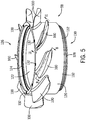
- FIG. 5 is a perspective view of an inner impeller section 58.
- the inner impeller section 58 includes a hub 120 with a plurality of impeller blades/airfoils 100 (e.g., 1, 2, 3, 4, 5, 6, 7, 8, 9, 10, or more).
- the impeller blades 100 may be integrally formed with the hub 120 (e.g., formed from one-piece) or may be separately coupled to the hub 120.
- the impeller blades 100 may be brazed and/or welded to the hub 120, or connected through a dovetail joint or similar.
- the hub 120 defines an aperture 122 that enables the inner impeller section 58 to receive the shaft 56 illustrated in FIGS. 3 and 4 and described above.
- the hub 120 defines a counterbore 124 at a first end 126 and a circumferential groove 128 at a second end 130. That is, the second end 130 with the circumferential groove 128 may be inserted into a counterbore 124 of a hub 120 of a neighboring inner impeller section 58. In this way, the inner impeller sections 58 may be stacked one on top of the other.
- the first end 126 and second end 130 may define a plurality of apertures 132 spaced about the circumference of the hub 120.
- apertures 132 may receive pins that couple neighboring inner impeller sections 58 together, facilitate alignment of neighboring inner impeller sections 58 to each other, as well as block rotation of the inner impeller sections 58 relative to each other. That is, pins placed in the apertures 132 on the first end 126 will also extend into apertures 132 on the second end 130 of a neighboring inner impeller section 58.
- FIG. 6 is a perspective view of an outer impeller section 64.
- the outer impeller section 64 includes a hub 140 that defines an aperture 142. It is within this aperture 142 along the inner circumferential surface 144 that the outer impeller section 64 includes a plurality of impeller blades/airfoils 110 (e.g., 1, 2, 3, 4, 5, 6, 7, 8, 9, 10, or more). These impeller blades 110 may be integrally formed with the hub 140 (e.g., made out of one-piece) or may be separately coupled to the hub 140. For example, the impeller blades 110 may be brazed and/or welded to the hub 140, or connected through a dovetail joint or similar.
- the hub 140 defines a plurality of apertures 146 on both the first end 148 and the second end 150. These apertures 146 may receive pins that couple neighboring outer impellers sections 64 together, facilitate alignment of neighboring outer impeller sections 64 to each other, as well as block rotation of the outer impeller sections 64 relative to each other. That is, pins in the apertures 146 on the first end 148 will extend into apertures 146 on the second end 150 of a neighboring outer impeller section 64.
- FIG. 7 is a side view of an impeller blade 100, 110.
- impeller blades 100, 110 rotate with the respective inner impeller sections 58 or the outer impeller sections 64.
- the impeller blades 100, 110 rotate (e.g., move in direction 168) about the central axis of the inner and outer impeller sections 58, 64, they drive and compress the fluid in the compressor section 54.
- the leading edge 170 of each impeller blade 100, 110 may be exposed to impacts from liquid droplets and/or solid particles in the fluid.
- impacts on the leading edge 170 are high angle impacts, meaning that the velocity vector of the droplet or particle is oriented at a high angle relative to a tangential impact surface of the impeller blade 100, 110.
- a velocity vector 172 of a particle e.g., liquid droplet, solid particle
- the impact angle 174 is measured between the velocity vector 172 and the tangent 176 of the impact surface location 178.
- a high impact angle 174 includes angles between 45°and 90°. Impacts at high angles on the impeller blade 100, 110 may rapidly wear the leading edge 170 because the particulate and/or droplet does not glance off the impeller blade 100, 110.
- a droplet and/or a particulate strikes the impeller blade 100, 110 with greater force.
- a low impact angle 179 formed by the velocity vector 180 with a tangent to the impact surface location 182 reduces the force of the droplet and/or particulate when striking the impeller blade 100, 110.
- a low impact angle 179 includes angles between 0° and 45°.
- Particle and/or droplet impacts at both high and low angles may cause erosion of the material of the impellerblades 100 and 110.
- the erosion may depend on the mass of the particulate impacting a surface, and on the velocity of the impinging particles.
- the dependence on the impact angle of the impinging articles is more complex, and varies between different materials. Accordingly, different materials may erode at different rates depending also on the angle of each impact.
- hard and dense materials such as tungsten carbide and diamond
- resist erosion better than softer and less dense materials, such as metals or plastics. It could thus be desirable to manufacture the impellers from a dense and hard material, like tungsten carbide.
- Other materials used to manufacture the impeller blades 100, 110 may include engineering ceramics such as silicon nitride, silicon carbide, boron carbide, aluminum oxide, and zirconia, or polycrystalline diamond. Such materials generally do not have desirable mechanical properties for mechanical parts exposed to high stress levels, such as the impellers blades 100, 110.
- hard and dense materials tend to be brittle, meaning that they have relatively low tensile yield strength, and that fracture propagation may happen rapidly and cause failures.
- the impeller blades 100, 110 of the present disclosure may include two or more different materials with different properties to increase erosion resistance. These materials may be placed at different locations on the impeller blades 100, 110 to increase erosion resistance from low and high angle impacts of particulate and/or droplets.
- the core/body 200 of the impeller blade 100, 110 is made from a strong and tough material (e.g., a high-strength steel, nickel-based super alloy, or or a titanium alloy). It is complemented by a coating or insert 202 on the leading edge 170.
- the first coating or insert 202 is made from a hard and dense material that resists impacts at high angles.
- the coating or insert 202 extends a distance 204 (e.g., a few millimeters to several centimeters) along the length of the impeller blade 100, 110 so that droplets and/or particulate striking the impeller blade 100, 110 at high impact angles primarily contact the coating or insert 202 as the impeller blade 100, 110 rotates in direction 168 (e.g., circumferential direction 66 or 68) about the central axis of the inner and/or outer impeller sections 58, 64.
- a high impact angle typically refers to an angle between 45°and 90° formed by the velocity vector of the droplet or particle and a tangent of the impact surface/point.
- impeller blade 100, 110 may define a groove 206 that extends over the leading edge 170 to accommodate the coating or insert 202 and to enable the coating or insert 202 to match the profile of the impeller blade 100, 110.
- the coating 202 may for axample be attached to the impeller blade 100, 110 over this groove 206 using high velocity oxygen fuel (HVOF), high velocity air fuel (HVAF), or D-Gun thermal spray, plasma spray, laser cladding, and Conforma Clad brazing. Many other application techniques are available.
- the coating 202 may for example be made from tungsten carbide, tungsten carbide-metal composite, polycrystalline diamond, or other ceramics or ceramic-metal composits. In some embodiments, if the coating 202 includes tungsten carbide the thickness of the coating 202 may be greater than 0.1 mm and less than 3 mm. A thickness greater than 3 mm may reduce the strength of the tungsten carbide coating.
- the coating 202 may be in form of an insert.
- the insert may be coupled to the impeller blade 100, 110 by brazing, gluing, welding, and/or a mechanical joint, e.g. a dovetail joint.
- the insert may be made from tungsten carbide, polycrystalline diamond, a metal ceramic composite, silicon nitride, silicon carbide, boron carbide, aluminum oxide, zirconia, or another ceramic.
- impeller blade 100, 110 may be exposed to droplet and particle impacts at lower angles, as explained above.
- the surfaces may include the upper surface 208 and the lower surface 210 (e.g., side surfaces), as well as the trailing edge 212, while hard and dense materials such as tungsten carbide resist erosion caused by low angle impacts as well and may be applied to the entire impeller blade surface. This maybe expensive and complicated.
- impeller blades generally call for accurate tolerances on the geometry of the impeller surface. Poor tolerances or rough surfaces may have a negative effect on the performance of the impeller, and may cause mechanical interference between parts.
- the geometrical accuracy and finish of the coated surfaces may be improved after application by machining, polishing or grinding, but this is also expensive and complicated, and may be time consuming.
- a second coating 214 may be applied to the other surfaces that encounter low-angle impacts.
- sprayed or vapor-deposited coatings may be used.
- Vapor deposited coatings may be applied to large surfaces in one operation, and the resulting second coating 214 is largely uniform with a smooth surface finish.
- the second coating 214 may therefore not need polishing or grinding down after application.
- Other application methods to apply the second coating 214 may also be used, such as thermal spray methods or plasma spray methods.
- the second coating 214 may be titanium aluminum nitride. This coating may be applied through the physical vapor deposition method. The second coating 214 may be uniformly deposited and/or applied to the leading edge 170, upper surface 208, lower surface 210, trailing edge 212, and/or the tip. The thickness of second coating 214 may be between 0.001mm and 0.5mm. The coating 214 may extend over the coating 202 on the leading edge 170 or may not be applied over the coating on the leading edge 170.
- FIG. 9 is a cross-sectional view of an impeller blade 100, 110 along line 8 - 8 of FIG. 5 .
- a core/body 230 of the impeller blade 100, 110 is made from a strong and tough material (e.g., a high-strength steel, nickel-based super alloy, or a titanium alloy).
- a strong and tough material e.g., a high-strength steel, nickel-based super alloy, or a titanium alloy.
- the impeller blade 100, 110 may include an insert 234 that couples to the core 230.
- the insert 234 may resist erosion from droplets and/or particulate that strikes against the leading edge 232 at high angles.
- the insert 234 extends a distance 236 (e.g., a few mm to several cm) from the end of the core 230 so that droplets and/or particulate striking the impeller blade 100, 110 at high impact angles primarily contact the insert 234 as the impeller blade 100, 110 rotates in direction 168 (e.g., circumferential direction 66 or 68) about the central axis of the inner and/or outer impeller sections 58, 64.
- a distance 236 e.g., a few mm to several cm
- a high impact angle may refer to an angle between 45° and 90° formed by the velocity vector of the droplet or particle and a tangent of the impact surface point.
- the insert 234 may be coupled to the impeller blade 100, 110 via a joint, such as a dovetail joint, or another joining method, e.g. glueing, brazing, or a fastener.
- the insert 234 may be made from tungsten carbide, polycrystalline diamond, a metal ceramic composite, silicon nitride, silicon carbide, boron carbide, aluminum oxide, zirconia, or another ceramic.
- insert 234 may include an insert body 238 and a coating 240 coupled to the insert body 238.
- the coating 240 may include tungsten carbide, polycrystalline diamond, engineering ceramics, or ceramic-metal composites. In some embodiments, if the coating 240 includes tungsten carbide the thickness of the coating 240 may be greater than 0.1 mm and less than 3 mm. A thickness greater than 3 mm may reduce the strength of the tungsten carbide coating. As explained above, a coating 242 may be applied to the other surfaces that encounter low-angle impacts. These surfaces include an upper or first side surface 244, a lower or second side surface 246, trailing edge 248, and/or the tip. For example, the coating 242 may be a vapor-deposited coating of titanium aluminum nitride.
- the coating 242 may be titanium nitride, chromium nitride, chromium aluminium titanium nitride, a diamond like coating, or multiple layers of various of these and other coatings.
- the thickness of coating 242 may be between 0.001mm and 0.5mm.
- the coating 242 may extend over the insert 234 or may not be applied over the insert 234 on the leading edge 232.
- FIG. 10 is a cross-sectional view of an impeller blade 100, 110 along line 8 - 8 of FIG. 5 .
- a core/body 260 of the impeller blade 100, 110 is made from a strong and tough material (e.g., a high-strength steel, nickel-based super alloy, or a titanium alloyy.
- a strong and tough material e.g., a high-strength steel, nickel-based super alloy, or a titanium alloyy.
- the impeller blade 100, 110 may include an insert or coating 264 that couples to the core 260.
- the insert or coating 264 may resist erosion from droplets and/or particulate that strikes against the leading edge 262 at high angles.
- the insert or coating 264 extends a distance 266 (e.g., a few mm to several cm) so that droplets and/or particulate striking the impeller blade 100, 110 at high impact angles primarily contact the insert or coating 264 as the impeller blade 100, 110 moves in direction 168 (e.g., circumferential direction 66 or 68) about the central axis of the inner and/or outer impeller sections 58, 64.
- a high impact angle may refer to an angle between 45°and 90° formed by the velocity vector of the droplet or particle and a tangent of the impact surface point.
- impeller blade 100, 110 may not include a groove; instead, the insert or coating 264 may taper in thickness as it extends over the leading edge 262.
- the coating 264 may be attached to the impeller blade 100, 110 using high velocity oxygen fuel (HVOF), high velocity air fuel (HVAF) and D-Gun thermal spray, plasma Spray, laser cladding, and Conforma Clad brazing.
- the coating 264 may be made from tungsten carbide, tungsten carbide-metal composite, polycrystalline diamond, or other ceramics or ceramic-metal composits. If the coating 264 is in the form of an insert, the insert may be coupled to the impeller blade 100, 110 by brazing, gluing, welding, or mechanical joining, e.g. a dovetail joint.
- the insert may be made from tungsten carbide, polycrystalline diamond, a metal ceramic composite, silicon nitride, silicon carbide, boron carbide, aluminum oxide, zirconia, or another ceramic.
- the thickness of the coating 264 may be greater than 0.1 mm and less than 3 mm. A thickness greater than 3 mm may reduce the strength of the tungsten carbide coating.
- a second coating 268 may be applied to other surfaces of the impeller blade 100, 110 that receive low-angle impacts. These surfaces include an upper or first side surface 270, a lower or second side surface 272, trailing edge 274, and/or the tip.
- the coating 268 may be a vapor-deposited coating of titanium aluminum nitride.
- the coating 268 may be titanium nitride, chromium nitride, chromium aluminium titanium nitride, a diamond like coating, or multiple layers of various of these and other coatings.
- the coating 268 may extend over the coating 264 on the leading edge 262 or may not be applied over the coating 264 on the leading edge 262.
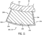
- FIG. 11 is a cross-sectional view of an impeller blade 100 along line 11 - 11 of FIG. 5 .
- the inner and outer impellers sections 58, 64 are stacked on top of each other with the inner impellers sections 58 resting within a neighboring outer impeller section 64. This places a tip 290 of the impeller blade 100 proximate the interior circumferential surface 144 of the hub 140 of the outer impeller section 64, and likewise the tip of impeller blade 110 proximate the hub 120 of the inner impeller section 58.
- the clearance between the impeller blades 100, 110 and the inner and outer impellers sections 58, 64 is small (e.g., less than 1mm or a few mm).
- the tip of the impeller blades 100, 110 are exposed to abrasive wear cause by particles bouncing between the tips of the impeller blades 100, 110 and the opposing hub 120, 140.
- a coating or insert may therefore be applied to the tips of the impeller blades 100, 110 in the same manner as that of the leading edge described above.
- a core 292 of the impeller blade 100 may be made from a strong and tough material (e.g., a high-strength steel, nickel-based super alloy, or a titanium alloy).
- the impeller blade 100 may include an insert or coating 294 that couples to the core 292 along the tip 290.
- the insert or coating 294 may resist erosion from droplets and/or particulate that strikes and/or abrades against the tip 290.
- the insert or coating 294 extends along the tip 290 between the leading edge 296 and the trailing edge 298.
- the coating 264 may be attached to the impeller blade 100 using high velocity oxygen fuel (HVOF), high velocity air fuel (HVAF) and D-Gun thermal spray, plasma spray, laser cladding, and Conforma Clad brazing.
- the coating 294 may be made from tungsten carbide, tungsten carbide-metal composite, polycrystalline diamond, or other ceramics or ceramic-metal composits. If the coating 264 is in the form of an insert, the insert may be coupled to tip 290 of the impeller blade 100 by brazing, gluing, welding, and/or with a mechanical joint (e.g., dovetail joint olr a joint using fasteners).
- the insert may be made from tungsten carbide, polycrystalline diamond, a metal ceramic composite, silicon nitride, silicon carbide, boron carbide, aluminum oxide, zirconia, or another ceramic.
- a coating 300 may be applied to the other surfaces that encounter low-angle impacts.
- sprayed or vapor-deposited coatings may be used.
- Vapor deposited coatings may be applied to large surfaces in one operation, and the resulting coating is largely uniform with a smooth surface finish.
- the coating 300 may therefore not be polished or ground down after application.
- Other application methods may also be used, such as thermal spray methods or plasma spray methods.
- the coating 300 may include titanium aluminum nitride.
- the coating 300 may be titanium nitride, chromium nitride, chromium aluminium titanium nitride, a diamond like coating, or multiple layers of various of these and other coatings.
- the coating 300 may be uniformly deposited and/or applied to the leading edge 296, upper surface, lower surface, trailing edge 298, and/or the tip 290. If desirable, parts of the suface may not be coated. This can for instance be avoided by masking certain parts ofr the surface before application of the coating 300. While the discussion of FIG. 11 has focused on impeller blades 100 on the inner impeller sections 58, the discussion is equally applicable to the impeller blades 110 of the outer impeller sections 64.
- FIG. 12 is a method 320 of manufacturing an impeller blade (e.g., 100, 110) or impeller (e.g. 58, 64).
- the method 320 begins by obtaining material for the impeller or impeller blade, block 322.
- the impeller blade material may include a high-strength steel, nickel-based super alloy, or a titanium alloy.
- the material may then be machined or otherwise formed to a target geometry, block 324.
- the impeller and/or impeller blade may be made by additive manufacturing and therefore the step in block 324 may be optional.
- the method 320 may include an optional step of machining/forming a groove or grooves in the impeller blade by removing material (e.g., leading edge, tip), block 326.
- the grooves may facilitate placement of the coating and/or insert on the impeller blade.
- the method 320 then applies a first coating (i.e., hard and dense coating) or insert to the leading edge of the impeller blade, block 328.
- the hard and dense coating or insert may include carbide, tungsten carbide-metal composite, polycrystalline diamond, or other ceramics or ceramic-metal composits.
- the method 320 may include an optional step of applying a first coating (i.e., hard and dense coating) or insert to the tip of the impeller blade, block 330.
- a first coating i.e., hard and dense coating
- the tip of the impellers may be exposed to abrasive wear cause by particles bouncing between the tips of the impeller blades and the opposing hub. Accordingly, a coating or insert may therefore be applied to the tip in the same manner as to the leading edge as described above.
- the method 320 may include the optional step of grinding the coated surfaces (e.g., tip, leading edge) with the hard and dense material to obtain the final geometry and an acceptable surface, block 332.
- the method 320 continues by preparing the impeller blade for application of a second coating (e.g., a vapor deposited coating), block 334.
- This preparation may include masking coated surfaces (i.e., surfaces coated with the hard and dense coating) or inserts on the impeller blade.
- the method 320 may then apply a second coating to the impeller blade, such as by vapor deposition, block 336.
- the second coating may cover the hard and dense coating as well as previously uncoated surfaces of the impeller blade. These surfaces may include the upper or first side surface, the lower or second side surface, the leading edge, the trailing edge, and/or the tip.
- the second coating may not be used and thus the steps in block 334 and 336 may be optional.
- the terms “inner” and “outer”; “up” and “down”; “upper” and “lower”; “upward” and “downward”; “above” and “below”; “inward” and “outward”; and other like terms as used herein refer to relative positions to one another and are not intended to denote a particular direction or spatial orientation.
- the terms “couple,” “coupled,” “connect,” “connection,” “connected,” “in connection with,” and “connecting” refer to “in direct connection with” or “in connection with via one or more intermediate elements or members.”
Landscapes
- Engineering & Computer Science (AREA)
- Mechanical Engineering (AREA)
- General Engineering & Computer Science (AREA)
- Chemical & Material Sciences (AREA)
- Materials Engineering (AREA)
- Chemical Kinetics & Catalysis (AREA)
- Metallurgy (AREA)
- Organic Chemistry (AREA)
- Structures Of Non-Positive Displacement Pumps (AREA)
Applications Claiming Priority (1)
| Application Number | Priority Date | Filing Date | Title |
|---|---|---|---|
| US201762572978P | 2017-10-16 | 2017-10-16 |
Publications (1)
| Publication Number | Publication Date |
|---|---|
| EP3470680A1 true EP3470680A1 (fr) | 2019-04-17 |
Family
ID=63878415
Family Applications (1)
| Application Number | Title | Priority Date | Filing Date |
|---|---|---|---|
| EP18200737.7A Pending EP3470680A1 (fr) | 2017-10-16 | 2018-10-16 | Lames résistant à l'érosion pour compresseurs |
Country Status (2)
| Country | Link |
|---|---|
| US (1) | US10914183B2 (fr) |
| EP (1) | EP3470680A1 (fr) |
Families Citing this family (2)
| Publication number | Priority date | Publication date | Assignee | Title |
|---|---|---|---|---|
| DE102020003854A1 (de) * | 2020-06-26 | 2021-12-30 | KSB SE & Co. KGaA | Kreiselpumpe zur Förderung feststoffhaltiger Medien |
| CN114918628B (zh) * | 2022-06-20 | 2023-09-15 | 江苏金通灵鼓风机有限公司 | 一种大型闭式碳化钨防磨叶轮的制作方法 |
Citations (5)
| Publication number | Priority date | Publication date | Assignee | Title |
|---|---|---|---|---|
| US5248386A (en) * | 1991-02-08 | 1993-09-28 | Aluminum Company Of America | Milling solution and method |
| EP1302562A1 (fr) * | 2001-10-12 | 2003-04-16 | General Electric Company | Procédé pour l'enlèvement d'un revêtment métallique d'une aube de turbomachine |
| US7186092B2 (en) * | 2004-07-26 | 2007-03-06 | General Electric Company | Airfoil having improved impact and erosion resistance and method for preparing same |
| US20140272166A1 (en) * | 2013-03-13 | 2014-09-18 | Rolls-Royce Corporation | Coating system for improved leading edge erosion protection |
| WO2017012761A1 (fr) * | 2015-07-23 | 2017-01-26 | Onesubsea Ip Uk Limited | Pompe ou compresseur sous-marin sans à-coups et procédé associé |
Family Cites Families (25)
| Publication number | Priority date | Publication date | Assignee | Title |
|---|---|---|---|---|
| US4576874A (en) * | 1984-10-03 | 1986-03-18 | Westinghouse Electric Corp. | Spalling and corrosion resistant ceramic coating for land and marine combustion turbines |
| DE69706850T2 (de) * | 1996-06-13 | 2002-05-16 | Siemens Ag | Artikel mit schutzschicht, enthaltend eine verbesserte verankerungsschicht und seine herstellung |
| US6095755A (en) * | 1996-11-26 | 2000-08-01 | United Technologies Corporation | Gas turbine engine airfoils having increased fatigue strength |
| JP2001521992A (ja) * | 1997-11-03 | 2001-11-13 | シーメンス アクチエンゲゼルシヤフト | 高温ガスの衝流を受ける構造部材及びこの構造部材への被膜の形成方法 |
| EP1029101B1 (fr) * | 1997-11-03 | 2001-09-12 | Siemens Aktiengesellschaft | Produit, en particulier composant d'une turbine a gaz, a couche thermo-isolante en ceramique, et procede pour obtenir ladit produit |
| DE59801547D1 (de) * | 1997-11-03 | 2001-10-25 | Siemens Ag | Erzeugnis, insbesondere bauteil einer gasturbine, mit keramischer wärmedämmschicht |
| US6733907B2 (en) * | 1998-03-27 | 2004-05-11 | Siemens Westinghouse Power Corporation | Hybrid ceramic material composed of insulating and structural ceramic layers |
| US6649682B1 (en) | 1998-12-22 | 2003-11-18 | Conforma Clad, Inc | Process for making wear-resistant coatings |
| US6933052B2 (en) * | 2003-10-08 | 2005-08-23 | General Electric Company | Diffusion barrier and protective coating for turbine engine component and method for forming |
| WO2005068685A1 (fr) * | 2004-01-15 | 2005-07-28 | Ebara Corporation | Revetement en alliage pour barriere de diffusion, procede d'elaboration, et element de dispositif haute temperature |
| US20050255329A1 (en) * | 2004-05-12 | 2005-11-17 | General Electric Company | Superalloy article having corrosion resistant coating thereon |
| US8118561B2 (en) * | 2004-07-26 | 2012-02-21 | General Electric Company | Erosion- and impact-resistant coatings |
| DE102007005755A1 (de) * | 2007-02-06 | 2008-08-07 | Mtu Aero Engines Gmbh | Vorrichtung zum Schutz von Bauteilen mit brennbarer Titanlegierung vor Titanfeuer und Verfahren zu deren Herstellung |
| US20100247321A1 (en) * | 2008-01-08 | 2010-09-30 | General Electric Company | Anti-fouling coatings and articles coated therewith |
| US8790789B2 (en) * | 2008-05-29 | 2014-07-29 | General Electric Company | Erosion and corrosion resistant coatings, methods and articles |
| US20100304107A1 (en) * | 2009-05-27 | 2010-12-02 | United Technologies Corporation | Layered coating for erosion protection |
| US20100304084A1 (en) * | 2009-05-29 | 2010-12-02 | General Electric Company | Protective coatings which provide erosion resistance, and related articles and methods |
| US20100304181A1 (en) * | 2009-05-29 | 2010-12-02 | General Electric Company | Protective coatings which provide erosion resistance, and related articles and methods |
| US20110116906A1 (en) * | 2009-11-17 | 2011-05-19 | Smith Blair A | Airfoil component wear indicator |
| US20110165433A1 (en) * | 2010-01-06 | 2011-07-07 | General Electric Company | Erosion and corrosion resistant coating system for compressor |
| US20130199934A1 (en) * | 2012-02-06 | 2013-08-08 | United Technologies Corporation | Electroformed sheath |
| US9476427B2 (en) | 2012-11-28 | 2016-10-25 | Framo Engineering As | Contra rotating wet gas compressor |
| US10041361B2 (en) * | 2014-10-15 | 2018-08-07 | General Electric Company | Turbine blade coating composition |
| US11933323B2 (en) | 2015-07-23 | 2024-03-19 | Onesubsea Ip Uk Limited | Short impeller for a turbomachine |
| CN111936664A (zh) * | 2018-03-19 | 2020-11-13 | 应用材料公司 | 在航空航天部件上沉积涂层的方法 |
-
2018
- 2018-10-16 US US16/161,125 patent/US10914183B2/en active Active
- 2018-10-16 EP EP18200737.7A patent/EP3470680A1/fr active Pending
Patent Citations (5)
| Publication number | Priority date | Publication date | Assignee | Title |
|---|---|---|---|---|
| US5248386A (en) * | 1991-02-08 | 1993-09-28 | Aluminum Company Of America | Milling solution and method |
| EP1302562A1 (fr) * | 2001-10-12 | 2003-04-16 | General Electric Company | Procédé pour l'enlèvement d'un revêtment métallique d'une aube de turbomachine |
| US7186092B2 (en) * | 2004-07-26 | 2007-03-06 | General Electric Company | Airfoil having improved impact and erosion resistance and method for preparing same |
| US20140272166A1 (en) * | 2013-03-13 | 2014-09-18 | Rolls-Royce Corporation | Coating system for improved leading edge erosion protection |
| WO2017012761A1 (fr) * | 2015-07-23 | 2017-01-26 | Onesubsea Ip Uk Limited | Pompe ou compresseur sous-marin sans à-coups et procédé associé |
Also Published As
| Publication number | Publication date |
|---|---|
| US20190112933A1 (en) | 2019-04-18 |
| US10914183B2 (en) | 2021-02-09 |
Similar Documents
| Publication | Publication Date | Title |
|---|---|---|
| US11306835B1 (en) | Flapper valves with hydrofoil and valve systems | |
| US10151188B2 (en) | System and method of reducing erosion in frac applications | |
| US7677308B2 (en) | Gas separator | |
| US10036398B2 (en) | Apparatus and system for a thrust-absorbing horizontal surface pump assembly | |
| US10914183B2 (en) | Erosion resistant blades for compressors | |
| CN105308259A (zh) | 耐磨气体分离器 | |
| US9506471B2 (en) | Radial bearing assembly for centrifugal pump | |
| CA2797164C (fr) | Pompe centrifuge pour boues | |
| US7204326B2 (en) | Drilling turbine | |
| Morrison et al. | The Measured Impact of Erosion on the Rotodynamic and Performance Characteristics of a Mixed Flow ESP | |
| US20240167607A1 (en) | Weight-optimized fluid-bearing pipe fittings enhancing fluid delivery system performance | |
| US12467340B2 (en) | Method and system for power generation | |
| WO2021080728A1 (fr) | Éléments de coupe de trépan et trépans équipés desdits éléments de coupe | |
| EP4031745B1 (fr) | Insert de déflecteur de guidage dans un trou d'écoulement | |
| US12612848B2 (en) | Centrifugal pump stage with radiused impeller flow passage exit for reduced erosion | |
| US20240384634A1 (en) | Centrifugal pump stage with radiused impeller flow passage exit for reduced erosion | |
| WO2018212773A1 (fr) | Ébauche de redressement de flux | |
| WO2025264277A1 (fr) | Étage de pompe centrifuge avec sortie de passage d'écoulement de turbine arrondie pour une érosion réduite | |
| RU68615U1 (ru) | Ступень (рабочий орган) погружного многоступенчатого насоса | |
| WO2020252064A1 (fr) | Améliorations apportées à des raccords de tuyau portant un fluide améliorant les performances d'un système de distribution de fluide | |
| CN110192037B (zh) | 用于离心泵的扭矩传递系统 | |
| Hamrick | Redesign of turbine-pump impeller and diffuser using hydrodynamic design techniques. Final report | |
| Mistry et al. | Centrifugal slurry pump wear and hydraulic studies. Phase II report. Experimental studies | |
| Phase | United States Department of Energy | |
| CA2887280A1 (fr) | Appareil et systeme destines a un dispositif de pompe de surface horizontale absorbant la poussee |
Legal Events
| Date | Code | Title | Description |
|---|---|---|---|
| PUAI | Public reference made under article 153(3) epc to a published international application that has entered the european phase |
Free format text: ORIGINAL CODE: 0009012 |
|
| STAA | Information on the status of an ep patent application or granted ep patent |
Free format text: STATUS: THE APPLICATION HAS BEEN PUBLISHED |
|
| AK | Designated contracting states |
Kind code of ref document: A1 Designated state(s): AL AT BE BG CH CY CZ DE DK EE ES FI FR GB GR HR HU IE IS IT LI LT LU LV MC MK MT NL NO PL PT RO RS SE SI SK SM TR |
|
| AX | Request for extension of the european patent |
Extension state: BA ME |
|
| STAA | Information on the status of an ep patent application or granted ep patent |
Free format text: STATUS: REQUEST FOR EXAMINATION WAS MADE |
|
| 17P | Request for examination filed |
Effective date: 20191011 |
|
| RBV | Designated contracting states (corrected) |
Designated state(s): AL AT BE BG CH CY CZ DE DK EE ES FI FR GB GR HR HU IE IS IT LI LT LU LV MC MK MT NL NO PL PT RO RS SE SI SK SM TR |
|
| STAA | Information on the status of an ep patent application or granted ep patent |
Free format text: STATUS: EXAMINATION IS IN PROGRESS |
|
| 17Q | First examination report despatched |
Effective date: 20210115 |