EP3470785B1 - Flanschgebundene rückkopplung für faseroptisches gyroskop (fog) - Google Patents
Flanschgebundene rückkopplung für faseroptisches gyroskop (fog) Download PDFInfo
- Publication number
- EP3470785B1 EP3470785B1 EP18000808.8A EP18000808A EP3470785B1 EP 3470785 B1 EP3470785 B1 EP 3470785B1 EP 18000808 A EP18000808 A EP 18000808A EP 3470785 B1 EP3470785 B1 EP 3470785B1
- Authority
- EP
- European Patent Office
- Prior art keywords
- optical fiber
- flange
- transition
- loopback
- orientation
- Prior art date
- Legal status (The legal status is an assumption and is not a legal conclusion. Google has not performed a legal analysis and makes no representation as to the accuracy of the status listed.)
- Active
Links
Images
Classifications
-
- G—PHYSICS
- G01—MEASURING; TESTING
- G01C—MEASURING DISTANCES, LEVELS OR BEARINGS; SURVEYING; NAVIGATION; GYROSCOPIC INSTRUMENTS; PHOTOGRAMMETRY OR VIDEOGRAMMETRY
- G01C19/00—Gyroscopes; Turn-sensitive devices using vibrating masses; Turn-sensitive devices without moving masses; Measuring angular rate using gyroscopic effects
- G01C19/58—Turn-sensitive devices without moving masses
- G01C19/64—Gyrometers using the Sagnac effect, i.e. rotation-induced shifts between counter-rotating electromagnetic beams
- G01C19/72—Gyrometers using the Sagnac effect, i.e. rotation-induced shifts between counter-rotating electromagnetic beams with counter-rotating light beams in a passive ring, e.g. fibre laser gyrometers
- G01C19/726—Phase nulling gyrometers, i.e. compensating the Sagnac phase shift in a closed loop system
-
- G—PHYSICS
- G01—MEASURING; TESTING
- G01C—MEASURING DISTANCES, LEVELS OR BEARINGS; SURVEYING; NAVIGATION; GYROSCOPIC INSTRUMENTS; PHOTOGRAMMETRY OR VIDEOGRAMMETRY
- G01C19/00—Gyroscopes; Turn-sensitive devices using vibrating masses; Turn-sensitive devices without moving masses; Measuring angular rate using gyroscopic effects
- G01C19/58—Turn-sensitive devices without moving masses
- G01C19/64—Gyrometers using the Sagnac effect, i.e. rotation-induced shifts between counter-rotating electromagnetic beams
- G01C19/72—Gyrometers using the Sagnac effect, i.e. rotation-induced shifts between counter-rotating electromagnetic beams with counter-rotating light beams in a passive ring, e.g. fibre laser gyrometers
- G01C19/721—Details, e.g. optical or electronical details
- G01C19/722—Details, e.g. optical or electronical details of the mechanical construction
Definitions
- This disclosure relates generally to sensor systems, and specifically to a flange-bonded loopback for a fiber-optic gyroscope (FOG).
- FOG fiber-optic gyroscope
- gyroscope systems that are configured to measure angular rotation rate about a sensitive (e.g., input) axis.
- Some gyroscopes implement optical signals to determine angular rotation rate about the sensitive axis.
- optical signal gyroscopes can monitor changes in phase of the optical signals to determine rotation about the sensitive axis.
- a fiber optic gyroscope can sense a change in orientation using the Sagnac effect, such as based on the interference of light which has passed through a coil of optical fiber (e.g., that is more than a kilometer long).
- a FOG can be implemented using two beams from a light source that are injected into the same fiber in opposite directions, such that the beam travelling against the rotation experiences a slightly shorter path delay than the other beam.
- the differential phase shift can be measured through interferometry, thus translating angular velocity into a shift of the interference pattern which is measured photometrically.
- the coils employed in the fiber optic gyroscopes can comprise a loopback portion wherein the fiber reverses direction. These portions may be subject to thermally-induced stresses that can arise from thermal expansion of the optical fiber coil portions of the optical fiber.
- a fiber optic assembly according to claim 1 is provided.
- a method of fabricating a fiber optic assembly according to claim 10 is provided.
- the FOG can include a spool that includes a flange coupled to one of the ends. As described herein, the FOG can include one or two flanges, but for purposes of the flange-bonded loopback, only one flange will be discussed herein.
- the FOG also includes an optical fiber that includes an optical fiber coil portion that is counter-wound in a first orientation and in a second orientation opposite the first orientation. The optical fiber also includes a first transition portion associated with a first orientation of the optical fiber coil portion and a second transition portion associated with a second orientation of the optical fiber coil portion.
- the first and second transition portions are arranged proximal to opposite ends of the optical fiber, such that the ends of the optical fiber each receive an optical beam that is implemented to determine angular rotation rate of the FOG about a sensitive axis (e.g., based on a relative phase difference of the optical beam at each of the ends of the optical fiber).
- the flange includes a first surface to which the optical fiber winding portion is coupled, and also includes a second surface opposite the first surface spool to which a loopback portion of the optical fiber is coupled.
- the optical fiber also includes a loopback portion that is coupled to the first and second transition portions and is secured to the flange.
- the loopback portion can be secured to the second surface of the flange opposite the first surface to which the optical fiber coil portion is coupled.
- the loopback portion is not subject to thermally-induced stresses that can arise from thermal expansion of the optical fiber coil portions of the optical fiber, as can be the case for typical FOG systems in which the loopback portion is coupled to the optical fiber coil portion (e.g., at a peripheral side of the optical fiber coil portion) of the optical fiber.
- the first and second transition portions can be arranged symmetrical with respect to each other between the optical fiber coil portion and the loopback portion.
- the optical fiber coil can be arranged symmetrically with respect to each orientation at the loopback portion. Accordingly, the optical signal path through the optical fiber for the optical signal provided at both the first and second transition portions can be symmetrical and equal to substantially mitigate errors in determining the angular rotation rate of the FOG about the sensitive axis.
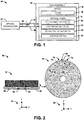
- FIG. 1 illustrates an example of a FOG system 10.
- the FOG system 10 can be implemented in any of a variety of applications in which accurate rotation of a device or vehicle is required.
- the FOG system 10 can be used for navigation (e.g., nautical or aerospace) and/or positioning (e.g., satellites or ordnance).
- the FOG system 10 includes a FOG assembly 12 that includes a spool 14 and an optical fiber 16.
- the spool 14 corresponds to a rigid body to which the optical fiber 16 is coupled.
- the spool 14 can also include one or more securing components for securing the FOG assembly 12, for example to a vehicle body (not shown), for determining rotation of the FOG assembly 12 about a sensitive axis.
- the optical fiber 16 includes an optical fiber coil portion 20 that is coupled to the spool 14.
- the optical fiber coil portion 20 includes the optical fiber 16 being counter-wound in a first orientation about a central axis (e.g., a sensitive axis) and in a second orientation (e.g., the.sensitive axis) opposite the first orientation.
- the optical fiber coil portion 20 can be secured in a solidified liquid material (e.g., an epoxy or other type of material that holds the optical fiber 16 in a ring-shaped arrangement of the optical fiber coil portion 20; hereinafter referred to as "potting material").
- the spool 14 includes a flange 18.
- the flange 18 can have an outer diameter that is approximately equal to (e.g., slightly greater than) an outer diameter of the optical fiber coil portion 20.
- the flange 18 can have a first surface to which the optical fiber coil portion 20 is coupled and a second surface opposite the first surface.
- the flange 18 can be formed integral with the spool 14, or can be formed as a separate piece that is secured to other portions of the spool 14.
- the optical fiber 16 is also demonstrated as having a first transition portion 22 and a second transition portion 24.
- transition portion with respect to the first transition portion 22 and the second transition portion 24 of the optical fiber 16 describes respective portions of the optical fiber 16 between the optical fiber coil portion 20 (e.g., as extending from the potting material) and a longitudinal coupling portion 28.
- the longitudinal coupling portion 28 is coupled to an optical transceiver 30 that is configured to generate an optical signal OPT that is provided to each of the respective ends associated with the optical fiber 16.
- the term "longitudinal coupling" with respect to the optical fiber 16 refers to a portion of the optical fiber 16 that is coupled to and extends between the first and second transition portions 22 and 24 and the optical transceiver 30, such that two separate lengths of the optical fiber 16 are coupled together along the length of the longitudinal coupling portion 28 to form a bidirectional fiber-optic cable.
- a portion of the longitudinal coupling portion 30 can be secured to the flange 18.
- the optical fiber 16 includes a loopback portion 32.
- the term "loopback portion” describes a partial loop of the first transition portion 22 and/or the longitudinal coupling portion 28 of the optical fiber 16 that is coupled to the first and second transition portions 22 and 24, such that the loopback portion 32 substantially reverses the direction orientation of the optical fiber 16 with respect to the first orientation direction of the optical fiber coil portion 20.
- the loopback portion 32 is coupled to the flange 18, such as at one of the first and second surfaces (e.g., the second surface) of the flange 18, along with the first and second transition portions 22 and 24.
- the loopback portion 32 being secured to the flange 18 enables the optical fiber 16 to be implemented to provide a symmetric signal path for the optical signal OPT in each direction through the optical fiber 16. Additionally, by securing the loopback portion 32 to the second surface of the flange 18, as opposed to the outer periphery of the optical fiber coil portion 20 (e.g., the peripheral outer surface of the potting material) of the optical fiber 16 (e.g., as arranged in typical FOG systems), thermal stresses that can affect the optical fiber 16, and thus can affect the optical signal OPT resulting in measurement errors, can be substantially mitigated.
- FIG. 2 illustrates an example diagram 50 of a FOG assembly.
- the FOG assembly is demonstrated in the diagram 50 in a first view 52 and a second view 54 that are orthogonal based on the Cartesian coordinate system 56.
- the FOG assembly can correspond to the FOG assembly 12 in the example of FIG. 1 . Therefore, reference is to be made to the example of FIG. 1 in the following description of the example of FIG. 2 .
- the FOG assembly includes a flange 58 that can be configured as part of a spool (e.g., the spool 14 in the example of FIG. 1 ).
- the FOG assembly also includes an optical fiber 60 that is demonstrated in the first view 52 example of FIG. 2 as interconnecting an optical fiber coil portion 62 and each of a first transition portion 64 and a second transition portion 66.
- the first and second transition portions 64 and 66 correspond to opposite orientations of the optical fiber 60 with respect to the optical fiber coil portion 62.
- the first and second transition portions 64 and 66 are demonstrated as symmetric with respect to each other (e.g., mirror-images) between the respective optical fiber coil portion 62 and a longitudinal coupling portion 68.
- the first transition portion 64 is demonstrated as being threaded through a respective first notch 70 in the flange 58 and the second transition portion 66 is demonstrated as being threaded through a respective second notch 72 in the flange 58. Therefore, the first notch 70 is configured to receive the first transition portion 64 of the optical fiber 60 at approximately a transition to the optical fiber coil portion 62 in the first orientation, whereas the optical fiber 60 is demonstrated as a dashed line 74 as it enters the optical fiber coil portion 62 in the first orientation on the opposing side of the flange 58. Similarly, the second notch 72 is configured to receive the second transition portion 66 of the optical fiber 60 at approximately a transition to the second optical fiber coil portion 62 in the second orientation. Accordingly, the notches 70 and 72 can facilitate securing of the optical fiber 60 to the second surface of the flange 58.
- the longitudinal coupling portion 68 includes a loopback portion 76 that is secured to the second surface of the flange 58.
- the flange 58 can be formed to include a groove preform that is configured to receive at least one of the first transition portion 64, the second transition portion 66, and the longitudinal coupling portion 68, as well as the loopback portion 76.
- the groove preform can further secure the mounting of the first transition portion 64, the second transition portion 66, and/or the longitudinal coupling portion 68.
- the groove preform can be configured to mitigate lateral movement of the optical fiber 60 along the second surface of the flange 58, and can substantially mitigate breakage of the optical fiber 60 at the loopback portion 76.
- the groove preform can facilitate repeatable positioning of the loopback portion 76 from one FOG assembly to the next in a mass-fabrication of multiple FOG assemblies to ensure substantially similar performance among the FOG assemblies fabricated.
- the loopback portion 76 being secured to the flange 58 enables the optical fiber 60 to be implemented to provide a symmetric signal path for the optical signal OPT in each direction through the optical fiber 60.
- the signal path of the optical signal OPT can be approximately equal from each of the opposing ends of the optical fiber 60 (e.g., at the optical transceiver 30) to the optical fiber coil portion 62.
- the combined length of the first transition portion 64 and the first orientation of the optical fiber coil portion 62 is approximately equal to the combined length of the second transition portion 66 and the second orientation of the optical fiber coil portion 62. Accordingly, the FOG system that includes the FOG assembly in the diagram 50 can operate symmetrically to substantially mitigate errors associated with interpreting a phase difference of the optical signal OPT at each end of the optical fiber 60.
- the loopback portion 76 in the diagram 50 is substantially protected from stresses caused by thermal expansion of the optical fiber coil portion 62.
- the flange 58 can further include a buffer material, demonstrated in the first view 52 at 80, that is disposed on the second surface of the flange 58.
- the buffer material 80 can have a coefficient of thermal expansion (CTE) that is between the CTE of the optical fiber 60 and the CTE of the flange 58.
- CTE coefficient of thermal expansion
- the buffer material 80 can be formed to include the groove preform, as described previously.
- the buffer material 80 can further mitigate thermal stresses that can affect the loopback portion 76.
- the FOG assembly of the diagram 50 can thus exhibit a number of performance advantages over typical FOG systems. Particularly, based on the securing of the loopback portion 76 to the flange 58, the FOG assembly in the diagram 50 can substantially eliminate operator loopback build variability (e.g., based on the groove preform) to substantially improve fabrication cost and consistency. Additionally, the securing of the loopback portion 76 to the flange 58 can also result in substantial reduction of thermal Shupe sensitivity, and can also result in substantial reduction of "Tdotdot" sensitivity in measuring the angular rotation rate of the FOG system. Accordingly, the FOG assembly in the diagram 50 can exhibit significant improvements in measuring rotation rate of the FOG system about a sensitive axis.
- the diagram 50 demonstrates that the loopback portion 76 is coupled to the second surface of the flange 58, opposite the first surface of the flange 58 to which the optical fiber coil portion 62 is coupled.
- the loopback portion 76 of the optical fiber 60 can be provided, such that the securing of the loopback portion 76 to the flange 58 is not limited to as demonstrated in the example of FIG. 2 .
- the flange 58 can have a diameter that is sufficiently greater than the optical fiber coil portion 62 to facilitate securing the loopback portion 76 to the first surface of the flange 58, and thus the same surface to which the optical fiber coil portion 62 is coupled.
- the flange 58 can include at least one portion that extends orthogonally with respect to the planar diameter of the flange 58, and thus can extend along the Y-axis or -Y-axis with respect to the Cartesian coordinate system 56. Accordingly, as described herein, the securing of the first and second transition portions 64 and 66 and the loopback portion 76 is not limited to as described in the example of FIG. 2 .
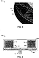
- FIG. 3 illustrates an example plan view of a FOG assembly 100.
- the FOG assembly 100 can correspond to the FOG assembly 12 in the example of FIG. 1 , or can represent the FOG assembly demonstrated in the diagram 50 in the example of FIG. 2 . Therefore, reference is to be made to the examples of FIGS. 1 and 2 in the following descriptions of the examples of FIG. 3 .
- the FOG assembly 100 includes a flange 104 that can be coupled to and/or part of a spool (e.g., the spool 14 in the example of FIG. 1 ).
- the FOG assembly 100 also includes an optical fiber 106 that includes an optical fiber coil portion 108 (e.g., that is encased/secured within a potting material) that is wound in opposite orientations.
- the optical fiber coil portion 108 is coupled to the flange 104 (e.g., a first surface).
- the FOG assembly 100 includes a buffer material 110 that interconnects the flange 104 and the optical fiber coil portion 108.
- the buffer material 110 can have a CTE that is between the CTE of the optical fiber coil portion 108 (e.g., of the potting material) and the CTE of the flange 104.
- the buffer material 110 can be formed from the same material as the optical fiber coil portion 108, and can thus have the same CTE as the optical fiber coil portion 108.
- the thermo-mechanical stress induced in the buffer material 110 due to a CTE mismatch between the optical fiber coil portion 108 and the buffer material 110 can decrease away from the flange 104 in an axial direction.
- the optical fiber 106 also includes a first transition portion 112 and a second transition portion 114 that are coupled to the optical fiber coil portion 108 via a first notch 116 and a second notch 118, respectively.
- the optical fiber 106 also includes a loopback portion 120 that is coupled to the first and second transition portions 112 and 114.
- the FOG assembly 100 includes a groove preform that is formed in a buffer material 122 on the second surface of the flange 104.
- the groove preform is configured to secure the first transition portion 112, the second transition portion 114, and the loopback portion 120 to the second surface of the flange 104.
- the groove preform can be formed from a buffer material having a CTE that is between the CTE of the optical fiber 106 and the flange 104.
- the groove preform can thus provide for a repeatable fabrication of the FOG assembly 100 with respect to the securing of the optical fiber 106 (e.g., including the first transition portion 112, the second transition portion 114, and the loopback portion 120) to the flange 104.
- the FOG assembly 100 can be easily fabricated, and can be fabricated in a manner that is consistent (e.g., with respect to performance) from one FOG assembly 100 to the next in a mass fabrication of FOG assemblies 100.
- FIG. 4 illustrates an example cross-sectional view of a FOG assembly 150.
- the FOG assembly 150 is demonstrated as an approximate diametrical cross-sectional view of the FOG assembly in the diagram 50 in the example of FIG. 2 . Therefore, reference is to be made to the examples of FIGS. 1 and 2 in the following description of the example of FIG. 4 .
- the FOG assembly 150 includes a spool 152 that includes a securing component 154 (e.g., a screw or bolt) and a flange 156.
- the FOG assembly 150 also includes a fiber optic coil portion 158 that is coupled to the flange 156 (on a first surface of the flange 156) via a buffer material 160.
- the fiber optic coil portion 158 and the buffer material 160 are enclosed within a magnetic shielding material 162 to substantially mitigate external electromagnetic interference that can deleteriously affect the performance of the associated FOG system.
- the FOG assembly 150 also includes a buffer material 164 that can be deposited on at least a portion of the flange 156 (e.g., the second surface of the flange 156).
- the buffer material 164 can be implemented to form a groove preform to receive the optical fiber (not shown in the example of FIG. 4 ), such as the first and second transition portions and/or the loopback portion of the optical fiber, to provide for repeatable fabrication of substantially identical arrangements of the first and second transition portions and/or the loopback portion from one FOG assembly 150 to the next.
- the FOG assembly 150 can be substantially enclosed within a covering material 166 to substantially protect the components within the covering material 166.
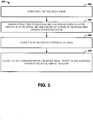
- FIG. 5 a methodology in accordance with various aspects of the present invention will be better appreciated with reference to FIG. 5 . While, for purposes of simplicity of explanation, the methodology of FIG. 5 is shown and described as executing serially, it is to be understood and appreciated that the present invention is not limited by the illustrated order, as some aspects could, in accordance with the present invention, occur in different orders and/or concurrently with other aspects from that shown and described herein. Moreover, not all illustrated features may be required to implement a methodology in accordance with an aspect of the present invention.
- FIG. 5 illustrates an example of a method 200 for fabricating a FOG assembly (e.g., the FOG assembly 12).
- a spool e.g., the spool 14
- a flange e.g., the flange 18
- an optical fiber e.g., the optical fiber 16
- an optical fiber coil portion e.g., the optical fiber coil portion 20
- the optical fiber further includes a first transition portion (e.g., the first transition portion 22) extending from the optical fiber coil portion and being associated with the first orientation and a second transition portion (e.g., the second transition portion 24) extending from the optical fiber coil portion and being associated with the second orientation.
- the optical fiber coil portion is coupled to the spool.
- the first transition portion, the second transition portion, and a loopback portion (e.g., the loopback portion 32) of the optical fiber are secured to the flange.
Landscapes
- Physics & Mathematics (AREA)
- Engineering & Computer Science (AREA)
- Power Engineering (AREA)
- Optics & Photonics (AREA)
- Electromagnetism (AREA)
- General Physics & Mathematics (AREA)
- Radar, Positioning & Navigation (AREA)
- Remote Sensing (AREA)
- Gyroscopes (AREA)
- Light Guides In General And Applications Therefor (AREA)
Claims (15)
- Anordnung (10, 12, 150) für einen faseroptischen Kreisel (fiber optic gyroscope - FOG), welche aufweist:eine Spule (14, 152), die einen Flansch (18, 58, 104, 156) aufweist; undeine Glasfaser (16, 60, 106), die einen Glasfaserwicklungsabschnitt (62, 108, 158) aufweist, der in einer ersten Ausrichtung und einer der ersten Ausrichtung entgegengesetzten zweiten Ausrichtung gegenläufig gewickelt ist, wobei der Glasfaserabschnitt (62, 108, 158) mit dem Flansch (18, 58, 104, 156) gekoppelt ist, wobei die Glasfaser (16, 60, 106) ferner einen Loopback-Abschnitt (32, 76, 120) aufweist, der die Richtungsausrichtung der Glasfaser (16, 60, 106) im Wesentlichen umkehrt, dadurch gekennzeichnet, dass der Loopback-Abschnitt an dem Flansch befestigt ist.
- FOG-Anordnung (10, 12, 150) nach Anspruch 1, wobei der Glasfaserwicklungsabschnitt (62, 108, 158) mit einer ersten Oberfläche des Flansches (18, 58, 104, 156) gekoppelt ist und wobei der Flansch (18, 58, 104, 156) ferner eine zweite Oberfläche gegenüber der ersten Oberfläche aufweist, wobei der Loopback-Abschnitt (32, 76, 120) mit der zweiten Oberfläche des Flansches (18, 58, 104, 156) gekoppelt ist.
- FOG-Anordnung (10, 12, 150) nach Anspruch 2, wobei die Glasfaser (16, 60, 106) ferner einen ersten Übergangsabschnitt (22, 64, 112), der der ersten Ausrichtung zugeordnet ist, einen zweiten Übergangsabschnitt (24, 66, 114), der der zweiten Ausrichtung zugeordnet ist, und einen Längskopplungsabschnitt (30, 65) aufweist, die an der zweiten Oberfläche des Flansches (18, 58, 104, 156) befestigt sind, wobei der erste und der zweite Übergangsabschnitt (22, 64, 112, 24, 66, 114) der Glasfaser (16, 60, 106) an der zweiten Oberfläche des Flansches (18, 58, 104, 156) befestigt sind und angeordnet sind, um annähernd symmetrisch zueinander auf dem Flansch (18, 58, 104, 156) angeordnet zu sein.
- FOG-Anordnung (10, 12, 150) nach Anspruch 3, wobei der Flansch (18, 58, 104, 156) ferner aufweist:eine erste Kerbe (70, 116), die an einem Umfang des Flansches (18, 58, 104, 136) angeordnet ist und konfiguriert ist, den ersten Übergangsabschnitt (22, 64, 112) der Glasfaser (16, 60, 106), der sich von dem Glasfaserwicklungsabschnitt (62, 108, 158) von der ersten Oberfläche des Flansches (18, 58, 104, 156) zur zweiten Oberfläche des Flansches (18, 58, 104, 156) erstreckt, aufzunehmen; undeine zweite Kerbe (72, 118), die an dem Umfang des Flansches (18, 58, 104, 156) angeordnet ist und konfiguriert ist, den zweiten Übergangsabschnitt (24, 66, 114) der Glasfaser (16, 60, 106), der sich von dem Glasfaserwicklungsabschnitt (62, 108, 158) von der ersten Oberfläche des Flansches (18, 58, 104, 156) zur zweiten Oberfläche des Flansches (18, 58, 104, 156) erstreckt, aufzunehmen.
- FOG-Anordnung (10, 12, 150) nach Anspruch 3, wobei der Loopback-Abschnitt (32, 76, 120) wenigstens einen Abschnitt des ersten Übergangsabschnitts (22, 64, 112) und des Längskopplungsabschnitts (30, 68) aufweist.
- FOG-Anordnung (10, 12, 150) nach Anspruch 1, wobei der Flansch (18, 58, 104, 156) eine Rillenvorform aufweist, die konfiguriert ist, die Glasfaser (16, 60, 106) entlang einer Länge der Rillenvorform bezogen auf wenigstens den Loopback-Abschnitt (32, 76, 120) aufzunehmen und zu befestigen.
- FOG-Anordnung (10, 12, 150) nach Anspruch 6, die ferner eine Puffermaterialschicht aufweist, die auf dem Flansch (18, 58, 104, 156) angeordnet ist, wobei die Rillenvorform in der Puffermaterialschicht ausgebildet ist, um die Glasfaser (16, 60, 106) zum Befestigen der Glasfaser (16, 60, 106), die den Loopback-Abschnitt (32, 76, 120) aufweist, am Flansch (18, 58, 104, 156) aufzunehmen.
- FOG-Anordnung (10, 12, 150) nach Anspruch 1, wobei die Glasfaser (16, 60, 106) ferner einen ersten Übergangsabschnitt (22, 64, 112), der der ersten Ausrichtung zugeordnet ist, einen zweiten Übergangsabschnitt (24, 66, 114), der der zweiten Ausrichtung zugeordnet ist, und einen Längskopplungsabschnitt (30, 68) aufweist, die an der zweiten Oberfläche des Flansches (18, 58, 104, 156) befestigt sind, wobei der erste und der zweite Übergangsabschnitt (22, 64, 112, 24, 66, 114) der Glasfaser (16, 60, 106) angeordnet sind, um annähernd symmetrisch zueinander auf dem Flansch (18, 58, 104, 156) angeordnet zu sein.
- FOG-Anordnung (10, 12, 150) nach Anspruch 1, die ferner einen optischen Transceiver (30) aufweist, der konfiguriert ist, ein optisches Signal zu erzeugen, das jedem Ende der Glasfaser (16, 60, 106) bereitgestellt wird, wobei Signalwege des optischen Signals von jedem Ende der Glasfaser (16, 60, 106) zu einem Abschnitt der Glasfaser (16, 60, 106), in dem eine Aufwicklung der Spule der Glasfaser (16, 60, 106) die Ausrichtung umkehrt, annähernd gleich sind.
- Verfahren zum Herstellen einer Anordnung (10, 12, 150) für einen faseroptischen Kreisel (FOG), wobei das Verfahren umfasst:Ausbilden einer Spule (14, 152), die einen Flansch (18, 58, 104, 156) aufweist;Ausbilden einer Glasfaser (16, 60, 106) in einen Glasfaserwicklungsabschnitt (62, 108, 158), der eine erste Ausrichtung der Glasfaser (16, 60, 106) und eine zweite Ausrichtung der Glasfaser (16, 60, 106), die der ersten Ausrichtung entgegengesetzt ist, aufweist, wobei die Glasfaser (16, 60, 106) ferner einen ersten Übergangsabschnitt (22, 64, 112), der sich vom Glasfaserwicklungsabschnitt (62, 108, 158) erstreckt und der ersten Ausrichtung zugeordnet ist, und einen zweiten Übergangsabschnitt (24, 66, 114), der sich von dem Glasfaserwicklungsabschnitt (62, 108, 158) erstreckt und der zweiten Ausrichtung zugeordnet ist, aufweist;Koppeln des Glasfaserspulenabschnitts (62, 108, 158) an die Spule (14, 152); undgekennzeichnet durchBefestigen des ersten Übergangsabschnitts (22, 64, 112), des zweiten Übergangsabschnitts (24, 66, 114) und eines Loopback-Abschnitts (32, 76, 120) der Glasfaser (16, 60, 106), der die Richtungsausrichtung der Glasfaser (16, 60, 106) im Wesentlichen umkehrt, an dem Flansch (18, 58, 104, 156).
- Verfahren nach Anspruch 10, wobei das Ausbilden der Spule (14, 152) das Ausbilden der Spule (14, 152) und des Flansches (18, 58, 104, 156), um bezogen auf ein sowohl der Spule (14, 152) als auch dem Flansch (18, 58, 104, 156) zugeordnetes Herstellungsmaterial einstückig zu sein, umfasst.
- Verfahren nach Anspruch 10, wobei das Koppeln des Glasfaserwicklungsabschnitts (62, 108, 158) an einer ersten Oberfläche des Flansches (18, 58, 104, 156) und wobei das Befestigen des ersten und des zweiten Übergangsabschnitts (22, 64, 112, 24, 66, 114) und des Loopback-Abschnitts (32, 76, 120) des Glasfaserwicklungsabschnitts (62, 108, 158) das Befestigen des ersten Übergangsabschnitts (22, 64, 112), des zweiten Übergangsabschnitts (24, 66, 114) und des Loopback-Abschnitts (32, 76, 120) an einer zweiten Oberfläche des Flansches (18, 38, 104, 156), die der ersten Oberfläche des Flansches (18, 58, 104, 156) gegenüberliegt, umfasst.
- Verfahren nach Anspruch 12, ferner umfassend:Ausbilden einer ersten Kerbe (70, 116) in einem Umfang des Flansches (18, 58, 104, 156),wobei das Befestigen des ersten Übergangsabschnitts (22, 64, 112) an der zweiten Oberfläche des Flansches (18, 58, 104, 156) das Erweitern des ersten Übergangsabschnitts (22, 64, 112) vom Glasfaserwicklungsabschnitt (62, 108, 158) auf der ersten Oberfläche des Flansches (18, 58, 104, 156) zur zweiten Oberfläche des Flansches (18, 55, 104, 156) über die erste Kerbe (70, 116) umfasst; undAusbilden einer zweiten Kerbe (72, 118) in dem Umfang des Flansches (18, 58, 104, 156) wobei das Befestigen des zweiten Übergangsabschnitts (24, 66, 114) an der zweiten Oberfläche des Flansches (18, 58, 104, 156) das Erweitern des zweiten Übergangsabschnitts (24, 66, 114) von dem Glasfaserwicklungsabschnitt (62, 108, 158) auf der ersten Oberfläche des Flansches (18, 58, 104, 156) zur zweiten Oberfläche des Flansches (18, 58, 104, 156) über die zweite Kerbe (72, 118) umfasst.
- Verfahren nach Anspruch 10, wobei das Befestigen des ersten und des zweiten Übergangsabschnitts (22, 64, 112, 24, 66, 114) und des Loopback-Abschnitts (32, 76, 120) des Glasfaserwicklungsabschnitts (62, 108, 158) umfasst: Befestigen des ersten und des zweiten Übergangsabschnitts (22, 64, 112, 24, 66, 114), sodass der erste und der zweite Übergangsabschnitt (22, 64, 112, 24, 66, 114) der Glasfaser (16, 60, 106) angeordnet sind, dass sie annähernd symmetrisch zueinander auf dem Flansch (18, 58, 104, 156) zwischen dem optischen Spulenabschnitt (62, 108, 158) und einem Längskopplungsabschnitt (30, 68) der Glasfaser (16, 60, 106) angeordnet sind.
- Verfahren nach Anspruch 10, das ferner umfasst:Ablagern eines Puffermaterials (80, 110, 122, 160, 164) auf dem Flansch; undAusbilden einer Rillenvorform im Puffermaterial (80, 110, 122, 160, 164), wobei das Befestigen des ersten und des zweiten Übergangsabschnitts (22, 64, 112, 24, 66, 114) und des Loopback-Abschnitts (32, 76, 120) des Glasfaserwicklungsabschnitts (62, 108, 158) das Befestigen des ersten Übergangsabschnitts (22, 64, 112), des zweiten Übergangsabschnitts (24, 66, 114) und des Loopback-Abschnitts (32, 76, 120) der Glasfaser (16, 60, 106) an den Flansch (18, 58, 104, 156) in der Rillenvorform umfasst.
Applications Claiming Priority (1)
| Application Number | Priority Date | Filing Date | Title |
|---|---|---|---|
| US15/783,299 US11047688B2 (en) | 2017-10-13 | 2017-10-13 | Flange-bonded loopback for fiber-optic gyroscope (FOG) |
Publications (2)
| Publication Number | Publication Date |
|---|---|
| EP3470785A1 EP3470785A1 (de) | 2019-04-17 |
| EP3470785B1 true EP3470785B1 (de) | 2020-12-02 |
Family
ID=63857668
Family Applications (1)
| Application Number | Title | Priority Date | Filing Date |
|---|---|---|---|
| EP18000808.8A Active EP3470785B1 (de) | 2017-10-13 | 2018-10-12 | Flanschgebundene rückkopplung für faseroptisches gyroskop (fog) |
Country Status (3)
| Country | Link |
|---|---|
| US (1) | US11047688B2 (de) |
| EP (1) | EP3470785B1 (de) |
| JP (1) | JP6600728B2 (de) |
Families Citing this family (3)
| Publication number | Priority date | Publication date | Assignee | Title |
|---|---|---|---|---|
| US11079230B2 (en) * | 2019-05-10 | 2021-08-03 | Northrop Grumman Systems Corporation | Fiber-optic gyroscope (FOG) assembly |
| US10989535B1 (en) * | 2020-01-31 | 2021-04-27 | Northrop Grumman Systems Corporation | Calibration circuit to mitigate fiber-optic gyroscope (FOG) bias error |
| US11788840B2 (en) | 2021-11-08 | 2023-10-17 | Northrop Grumman Systems Corporation | Vibrating-mass sensor system |
Family Cites Families (16)
| Publication number | Priority date | Publication date | Assignee | Title |
|---|---|---|---|---|
| DE3332718C2 (de) | 1983-09-10 | 1994-12-22 | Sel Alcatel Ag | Einrichtung zur Messung der Drehgeschwindigkeit |
| EP0228773A1 (de) | 1985-10-10 | 1987-07-15 | British Aerospace Public Limited Company | Bewegungsmessung |
| US4793708A (en) | 1987-03-27 | 1988-12-27 | Litton Systems Canada Limited | Fiber optic sensing coil |
| US5394233A (en) | 1993-04-06 | 1995-02-28 | Wang; Charles P. | Apparatus for measuring high frequency vibration, motion, or displacement |
| US5973783A (en) | 1998-07-31 | 1999-10-26 | Litton Systems, Inc. | Fiber optic gyroscope coil lead dressing and method for forming the same |
| US6763718B1 (en) | 2001-06-26 | 2004-07-20 | The United States Of America As Represented By The Secretary Of The Navy | Micro-electro-mechanical systems ultra-sensitive accelerometer with independent sensitivity adjustment |
| WO2002093594A1 (en) * | 2001-05-11 | 2002-11-21 | Fibersense Technology Corporation | Trapezoidal coil for fiber optic gyroscopes |
| US6685128B2 (en) | 2001-05-15 | 2004-02-03 | Northrop Grumman Corporation | Systems and methods of winding optical fiber |
| JP2005345230A (ja) | 2004-06-02 | 2005-12-15 | Tateyama Kagaku Kogyo Kk | 光干渉型センサ |
| US7355720B1 (en) | 2005-12-20 | 2008-04-08 | Sandia Corporation | Optical displacement sensor |
| US7626762B2 (en) | 2007-11-13 | 2009-12-01 | Honeywell International Inc. | Jog zone free fiber optic coil |
| US7808618B1 (en) | 2008-01-09 | 2010-10-05 | The Charles Stark Draper Laboratory, Inc. | Methods and apparatus for providing a semiconductor optical flexured mass accelerometer |
| JP4577376B2 (ja) * | 2008-02-21 | 2010-11-10 | ソニー株式会社 | 光導波路の製造方法 |
| CN101551249B (zh) | 2008-11-19 | 2011-04-27 | 北京航天时代光电科技有限公司 | 一种可分离式骨架及利用该骨架实现的光纤线圈制备方法 |
| GB2463332B (en) * | 2009-02-26 | 2011-05-25 | Advanced Fiber Products Ltd | Fibre optic connector assembly |
| CN102607548B (zh) | 2012-02-24 | 2014-12-31 | 北京航空航天大学 | 用于光纤陀螺的上下对称交叉绕制光纤环结构及绕制方法 |
-
2017
- 2017-10-13 US US15/783,299 patent/US11047688B2/en active Active
-
2018
- 2018-10-04 JP JP2018189058A patent/JP6600728B2/ja active Active
- 2018-10-12 EP EP18000808.8A patent/EP3470785B1/de active Active
Non-Patent Citations (1)
| Title |
|---|
| None * |
Also Published As
| Publication number | Publication date |
|---|---|
| JP6600728B2 (ja) | 2019-10-30 |
| US20190113343A1 (en) | 2019-04-18 |
| JP2019074517A (ja) | 2019-05-16 |
| EP3470785A1 (de) | 2019-04-17 |
| US11047688B2 (en) | 2021-06-29 |
Similar Documents
| Publication | Publication Date | Title |
|---|---|---|
| US7684659B1 (en) | Bifilar optical fiber stowage for fiber-optic gyroscope | |
| US8497994B2 (en) | Interferometer employing a multi-waveguide optical loop path and fiber optic rotation rate sensor employing same | |
| EP3470785B1 (de) | Flanschgebundene rückkopplung für faseroptisches gyroskop (fog) | |
| EP0694761B1 (de) | Lichtleitfaserkreisel mit hart eingegossener Aufnehmerspule | |
| CN111829499B (zh) | 一种基于光纤测温的高精度光纤陀螺系统及光纤环圈结构 | |
| JPH03195920A (ja) | 光ファイバ・ジャイロスコープ | |
| EP2878922B1 (de) | Resonanter faseroptischer Kreisel mit mehradriger Transportfaser | |
| Napoli et al. | Two decades of KVH fiber optic gyro technology: From large, low performance FOGs to compact, precise FOGs and FOG-based inertial systems | |
| EP2230484A1 (de) | Depolarisator für einen optische Faserkreisel unter Verwendung von Photonischer Kristallfaser mit hoher Doppelbrechung | |
| US5054922A (en) | Differential polarimetric fiber optic sensor | |
| JP7216951B2 (ja) | 干渉型光ファイバジャイロ及びセンシングコイル機構 | |
| EP3736533B1 (de) | Faseroptische gyroskop(fog)-anordnung | |
| CN112284371B (zh) | 一种干涉型光纤陀螺仪嵌套式多层多匝光纤环 | |
| US8301407B2 (en) | Stabilized solid-state gyrolaser | |
| JP2013253922A (ja) | 光電流センサ | |
| US6005665A (en) | Job zone for a high performance navigation grade rate sensing coil | |
| EP1535029B1 (de) | Fasergyroskop mit pufferlagen und vergussmaterial für die faserwicklung | |
| US8798405B2 (en) | Method of making a fiber optic gyroscope | |
| CN119780476B (zh) | 一种尾纤长度定量控制的光纤陀螺热致零漂极差优化方法 | |
| JPH07306049A (ja) | 光ファイバジャイロ | |
| JP2006153540A (ja) | サニャック干渉計型応力センサ | |
| Trommer et al. | Progress in passive fiber optic gyroscope development | |
| JP2006030007A (ja) | 光ファイバ電流センサ | |
| JPH01305311A (ja) | 光干渉角速度計 | |
| JPH04198811A (ja) | 光ファイバジャイロ |
Legal Events
| Date | Code | Title | Description |
|---|---|---|---|
| PUAI | Public reference made under article 153(3) epc to a published international application that has entered the european phase |
Free format text: ORIGINAL CODE: 0009012 |
|
| STAA | Information on the status of an ep patent application or granted ep patent |
Free format text: STATUS: THE APPLICATION HAS BEEN PUBLISHED |
|
| AK | Designated contracting states |
Kind code of ref document: A1 Designated state(s): AL AT BE BG CH CY CZ DE DK EE ES FI FR GB GR HR HU IE IS IT LI LT LU LV MC MK MT NL NO PL PT RO RS SE SI SK SM TR |
|
| AX | Request for extension of the european patent |
Extension state: BA ME |
|
| STAA | Information on the status of an ep patent application or granted ep patent |
Free format text: STATUS: REQUEST FOR EXAMINATION WAS MADE |
|
| 17P | Request for examination filed |
Effective date: 20190923 |
|
| RBV | Designated contracting states (corrected) |
Designated state(s): AL AT BE BG CH CY CZ DE DK EE ES FI FR GB GR HR HU IE IS IT LI LT LU LV MC MK MT NL NO PL PT RO RS SE SI SK SM TR |
|
| GRAP | Despatch of communication of intention to grant a patent |
Free format text: ORIGINAL CODE: EPIDOSNIGR1 |
|
| STAA | Information on the status of an ep patent application or granted ep patent |
Free format text: STATUS: GRANT OF PATENT IS INTENDED |
|
| INTG | Intention to grant announced |
Effective date: 20200605 |
|
| RAP1 | Party data changed (applicant data changed or rights of an application transferred) |
Owner name: NORTHROP GRUMMAN SYSTEMS CORPORATION |
|
| RIN1 | Information on inventor provided before grant (corrected) |
Inventor name: KIM, STEVEN M. Inventor name: ZIMMERMANN, GREGORY A. Inventor name: SAXENA, RAGINI Inventor name: LOVSTEDT, STEPHAN P. Inventor name: SNOW, WESLEY A. Inventor name: ROSETE, RICARDO A. |
|
| GRAS | Grant fee paid |
Free format text: ORIGINAL CODE: EPIDOSNIGR3 |
|
| GRAA | (expected) grant |
Free format text: ORIGINAL CODE: 0009210 |
|
| STAA | Information on the status of an ep patent application or granted ep patent |
Free format text: STATUS: THE PATENT HAS BEEN GRANTED |
|
| AK | Designated contracting states |
Kind code of ref document: B1 Designated state(s): AL AT BE BG CH CY CZ DE DK EE ES FI FR GB GR HR HU IE IS IT LI LT LU LV MC MK MT NL NO PL PT RO RS SE SI SK SM TR |
|
| REG | Reference to a national code |
Ref country code: GB Ref legal event code: FG4D |
|
| REG | Reference to a national code |
Ref country code: AT Ref legal event code: REF Ref document number: 1341414 Country of ref document: AT Kind code of ref document: T Effective date: 20201215 Ref country code: CH Ref legal event code: EP |
|
| REG | Reference to a national code |
Ref country code: DE Ref legal event code: R096 Ref document number: 602018010203 Country of ref document: DE |
|
| REG | Reference to a national code |
Ref country code: IE Ref legal event code: FG4D |
|
| PG25 | Lapsed in a contracting state [announced via postgrant information from national office to epo] |
Ref country code: RS Free format text: LAPSE BECAUSE OF FAILURE TO SUBMIT A TRANSLATION OF THE DESCRIPTION OR TO PAY THE FEE WITHIN THE PRESCRIBED TIME-LIMIT Effective date: 20201202 Ref country code: FI Free format text: LAPSE BECAUSE OF FAILURE TO SUBMIT A TRANSLATION OF THE DESCRIPTION OR TO PAY THE FEE WITHIN THE PRESCRIBED TIME-LIMIT Effective date: 20201202 Ref country code: GR Free format text: LAPSE BECAUSE OF FAILURE TO SUBMIT A TRANSLATION OF THE DESCRIPTION OR TO PAY THE FEE WITHIN THE PRESCRIBED TIME-LIMIT Effective date: 20210303 Ref country code: NO Free format text: LAPSE BECAUSE OF FAILURE TO SUBMIT A TRANSLATION OF THE DESCRIPTION OR TO PAY THE FEE WITHIN THE PRESCRIBED TIME-LIMIT Effective date: 20210302 |
|
| REG | Reference to a national code |
Ref country code: NL Ref legal event code: MP Effective date: 20201202 |
|
| REG | Reference to a national code |
Ref country code: AT Ref legal event code: MK05 Ref document number: 1341414 Country of ref document: AT Kind code of ref document: T Effective date: 20201202 |
|
| PG25 | Lapsed in a contracting state [announced via postgrant information from national office to epo] |
Ref country code: BG Free format text: LAPSE BECAUSE OF FAILURE TO SUBMIT A TRANSLATION OF THE DESCRIPTION OR TO PAY THE FEE WITHIN THE PRESCRIBED TIME-LIMIT Effective date: 20210302 Ref country code: LV Free format text: LAPSE BECAUSE OF FAILURE TO SUBMIT A TRANSLATION OF THE DESCRIPTION OR TO PAY THE FEE WITHIN THE PRESCRIBED TIME-LIMIT Effective date: 20201202 Ref country code: PL Free format text: LAPSE BECAUSE OF FAILURE TO SUBMIT A TRANSLATION OF THE DESCRIPTION OR TO PAY THE FEE WITHIN THE PRESCRIBED TIME-LIMIT Effective date: 20201202 Ref country code: SE Free format text: LAPSE BECAUSE OF FAILURE TO SUBMIT A TRANSLATION OF THE DESCRIPTION OR TO PAY THE FEE WITHIN THE PRESCRIBED TIME-LIMIT Effective date: 20201202 |
|
| PG25 | Lapsed in a contracting state [announced via postgrant information from national office to epo] |
Ref country code: HR Free format text: LAPSE BECAUSE OF FAILURE TO SUBMIT A TRANSLATION OF THE DESCRIPTION OR TO PAY THE FEE WITHIN THE PRESCRIBED TIME-LIMIT Effective date: 20201202 Ref country code: NL Free format text: LAPSE BECAUSE OF FAILURE TO SUBMIT A TRANSLATION OF THE DESCRIPTION OR TO PAY THE FEE WITHIN THE PRESCRIBED TIME-LIMIT Effective date: 20201202 |
|
| REG | Reference to a national code |
Ref country code: LT Ref legal event code: MG9D |
|
| PG25 | Lapsed in a contracting state [announced via postgrant information from national office to epo] |
Ref country code: SM Free format text: LAPSE BECAUSE OF FAILURE TO SUBMIT A TRANSLATION OF THE DESCRIPTION OR TO PAY THE FEE WITHIN THE PRESCRIBED TIME-LIMIT Effective date: 20201202 Ref country code: LT Free format text: LAPSE BECAUSE OF FAILURE TO SUBMIT A TRANSLATION OF THE DESCRIPTION OR TO PAY THE FEE WITHIN THE PRESCRIBED TIME-LIMIT Effective date: 20201202 Ref country code: CZ Free format text: LAPSE BECAUSE OF FAILURE TO SUBMIT A TRANSLATION OF THE DESCRIPTION OR TO PAY THE FEE WITHIN THE PRESCRIBED TIME-LIMIT Effective date: 20201202 Ref country code: EE Free format text: LAPSE BECAUSE OF FAILURE TO SUBMIT A TRANSLATION OF THE DESCRIPTION OR TO PAY THE FEE WITHIN THE PRESCRIBED TIME-LIMIT Effective date: 20201202 Ref country code: RO Free format text: LAPSE BECAUSE OF FAILURE TO SUBMIT A TRANSLATION OF THE DESCRIPTION OR TO PAY THE FEE WITHIN THE PRESCRIBED TIME-LIMIT Effective date: 20201202 Ref country code: SK Free format text: LAPSE BECAUSE OF FAILURE TO SUBMIT A TRANSLATION OF THE DESCRIPTION OR TO PAY THE FEE WITHIN THE PRESCRIBED TIME-LIMIT Effective date: 20201202 Ref country code: PT Free format text: LAPSE BECAUSE OF FAILURE TO SUBMIT A TRANSLATION OF THE DESCRIPTION OR TO PAY THE FEE WITHIN THE PRESCRIBED TIME-LIMIT Effective date: 20210405 |
|
| PG25 | Lapsed in a contracting state [announced via postgrant information from national office to epo] |
Ref country code: AT Free format text: LAPSE BECAUSE OF FAILURE TO SUBMIT A TRANSLATION OF THE DESCRIPTION OR TO PAY THE FEE WITHIN THE PRESCRIBED TIME-LIMIT Effective date: 20201202 |
|
| REG | Reference to a national code |
Ref country code: DE Ref legal event code: R097 Ref document number: 602018010203 Country of ref document: DE |
|
| PG25 | Lapsed in a contracting state [announced via postgrant information from national office to epo] |
Ref country code: IS Free format text: LAPSE BECAUSE OF FAILURE TO SUBMIT A TRANSLATION OF THE DESCRIPTION OR TO PAY THE FEE WITHIN THE PRESCRIBED TIME-LIMIT Effective date: 20210402 |
|
| PLBE | No opposition filed within time limit |
Free format text: ORIGINAL CODE: 0009261 |
|
| STAA | Information on the status of an ep patent application or granted ep patent |
Free format text: STATUS: NO OPPOSITION FILED WITHIN TIME LIMIT |
|
| PG25 | Lapsed in a contracting state [announced via postgrant information from national office to epo] |
Ref country code: AL Free format text: LAPSE BECAUSE OF FAILURE TO SUBMIT A TRANSLATION OF THE DESCRIPTION OR TO PAY THE FEE WITHIN THE PRESCRIBED TIME-LIMIT Effective date: 20201202 |
|
| 26N | No opposition filed |
Effective date: 20210903 |
|
| PG25 | Lapsed in a contracting state [announced via postgrant information from national office to epo] |
Ref country code: DK Free format text: LAPSE BECAUSE OF FAILURE TO SUBMIT A TRANSLATION OF THE DESCRIPTION OR TO PAY THE FEE WITHIN THE PRESCRIBED TIME-LIMIT Effective date: 20201202 Ref country code: SI Free format text: LAPSE BECAUSE OF FAILURE TO SUBMIT A TRANSLATION OF THE DESCRIPTION OR TO PAY THE FEE WITHIN THE PRESCRIBED TIME-LIMIT Effective date: 20201202 |
|
| PG25 | Lapsed in a contracting state [announced via postgrant information from national office to epo] |
Ref country code: ES Free format text: LAPSE BECAUSE OF FAILURE TO SUBMIT A TRANSLATION OF THE DESCRIPTION OR TO PAY THE FEE WITHIN THE PRESCRIBED TIME-LIMIT Effective date: 20201202 |
|
| REG | Reference to a national code |
Ref country code: CH Ref legal event code: PL |
|
| PG25 | Lapsed in a contracting state [announced via postgrant information from national office to epo] |
Ref country code: IS Free format text: LAPSE BECAUSE OF FAILURE TO SUBMIT A TRANSLATION OF THE DESCRIPTION OR TO PAY THE FEE WITHIN THE PRESCRIBED TIME-LIMIT Effective date: 20210402 |
|
| REG | Reference to a national code |
Ref country code: BE Ref legal event code: MM Effective date: 20211031 |
|
| PG25 | Lapsed in a contracting state [announced via postgrant information from national office to epo] |
Ref country code: MC Free format text: LAPSE BECAUSE OF FAILURE TO SUBMIT A TRANSLATION OF THE DESCRIPTION OR TO PAY THE FEE WITHIN THE PRESCRIBED TIME-LIMIT Effective date: 20201202 |
|
| REG | Reference to a national code |
Ref country code: DE Ref legal event code: R082 Ref document number: 602018010203 Country of ref document: DE Representative=s name: FARAGO PATENTANWAELTE GMBH, DE Ref country code: DE Ref legal event code: R082 Ref document number: 602018010203 Country of ref document: DE Representative=s name: FARAGO PATENTANWALTSGESELLSCHAFT MBH, DE |
|
| PG25 | Lapsed in a contracting state [announced via postgrant information from national office to epo] |
Ref country code: LU Free format text: LAPSE BECAUSE OF NON-PAYMENT OF DUE FEES Effective date: 20211012 Ref country code: BE Free format text: LAPSE BECAUSE OF NON-PAYMENT OF DUE FEES Effective date: 20211031 |
|
| PG25 | Lapsed in a contracting state [announced via postgrant information from national office to epo] |
Ref country code: LI Free format text: LAPSE BECAUSE OF NON-PAYMENT OF DUE FEES Effective date: 20211031 Ref country code: CH Free format text: LAPSE BECAUSE OF NON-PAYMENT OF DUE FEES Effective date: 20211031 |
|
| PG25 | Lapsed in a contracting state [announced via postgrant information from national office to epo] |
Ref country code: IE Free format text: LAPSE BECAUSE OF NON-PAYMENT OF DUE FEES Effective date: 20211012 |
|
| PG25 | Lapsed in a contracting state [announced via postgrant information from national office to epo] |
Ref country code: CY Free format text: LAPSE BECAUSE OF FAILURE TO SUBMIT A TRANSLATION OF THE DESCRIPTION OR TO PAY THE FEE WITHIN THE PRESCRIBED TIME-LIMIT Effective date: 20201202 |
|
| P01 | Opt-out of the competence of the unified patent court (upc) registered |
Effective date: 20230607 |
|
| PG25 | Lapsed in a contracting state [announced via postgrant information from national office to epo] |
Ref country code: HU Free format text: LAPSE BECAUSE OF FAILURE TO SUBMIT A TRANSLATION OF THE DESCRIPTION OR TO PAY THE FEE WITHIN THE PRESCRIBED TIME-LIMIT; INVALID AB INITIO Effective date: 20181012 |
|
| PG25 | Lapsed in a contracting state [announced via postgrant information from national office to epo] |
Ref country code: MK Free format text: LAPSE BECAUSE OF FAILURE TO SUBMIT A TRANSLATION OF THE DESCRIPTION OR TO PAY THE FEE WITHIN THE PRESCRIBED TIME-LIMIT Effective date: 20201202 |
|
| PG25 | Lapsed in a contracting state [announced via postgrant information from national office to epo] |
Ref country code: TR Free format text: LAPSE BECAUSE OF FAILURE TO SUBMIT A TRANSLATION OF THE DESCRIPTION OR TO PAY THE FEE WITHIN THE PRESCRIBED TIME-LIMIT Effective date: 20201202 |
|
| PG25 | Lapsed in a contracting state [announced via postgrant information from national office to epo] |
Ref country code: MT Free format text: LAPSE BECAUSE OF FAILURE TO SUBMIT A TRANSLATION OF THE DESCRIPTION OR TO PAY THE FEE WITHIN THE PRESCRIBED TIME-LIMIT Effective date: 20201202 |
|
| PGFP | Annual fee paid to national office [announced via postgrant information from national office to epo] |
Ref country code: DE Payment date: 20251021 Year of fee payment: 8 |
|
| PGFP | Annual fee paid to national office [announced via postgrant information from national office to epo] |
Ref country code: GB Payment date: 20251022 Year of fee payment: 8 |
|
| PGFP | Annual fee paid to national office [announced via postgrant information from national office to epo] |
Ref country code: IT Payment date: 20251024 Year of fee payment: 8 |
|
| PGFP | Annual fee paid to national office [announced via postgrant information from national office to epo] |
Ref country code: FR Payment date: 20251030 Year of fee payment: 8 |