EP3470802A1 - Dispositif de mesure du niveau de remplissage et procédé de détermination du niveau de remplissage d'un récipient - Google Patents
Dispositif de mesure du niveau de remplissage et procédé de détermination du niveau de remplissage d'un récipient Download PDFInfo
- Publication number
- EP3470802A1 EP3470802A1 EP17195994.3A EP17195994A EP3470802A1 EP 3470802 A1 EP3470802 A1 EP 3470802A1 EP 17195994 A EP17195994 A EP 17195994A EP 3470802 A1 EP3470802 A1 EP 3470802A1
- Authority
- EP
- European Patent Office
- Prior art keywords
- container
- level
- vibration
- measuring device
- sound
- Prior art date
- Legal status (The legal status is an assumption and is not a legal conclusion. Google has not performed a legal analysis and makes no representation as to the accuracy of the status listed.)
- Granted
Links
Images




Classifications
-
- G—PHYSICS
- G01—MEASURING; TESTING
- G01F—MEASURING VOLUME, VOLUME FLOW, MASS FLOW OR LIQUID LEVEL; METERING BY VOLUME
- G01F23/00—Indicating or measuring liquid level or level of fluent solid material, e.g. indicating in terms of volume or indicating by means of an alarm
- G01F23/22—Indicating or measuring liquid level or level of fluent solid material, e.g. indicating in terms of volume or indicating by means of an alarm by measuring physical variables, other than linear dimensions, pressure or weight, dependent on the level to be measured, e.g. by difference of heat transfer of steam or water
- G01F23/28—Indicating or measuring liquid level or level of fluent solid material, e.g. indicating in terms of volume or indicating by means of an alarm by measuring physical variables, other than linear dimensions, pressure or weight, dependent on the level to be measured, e.g. by difference of heat transfer of steam or water by measuring the variations of parameters of electromagnetic or acoustic waves applied directly to the liquid or fluent solid material
- G01F23/296—Acoustic waves
- G01F23/2965—Measuring attenuation of transmitted waves
Definitions
- the invention relates to a level measuring device for determining the level of a container via vibration and / or sound pressure changes, which are triggered by a vibration generating device.
- the invention further relates to a kit for a container and at least one such level gauge.
- the invention also relates to a method for determining the level of a container with at least one level gauge via vibration and / or sound pressure changes triggered by a vibration generating device and the use of the level gauge for determining the amount of contents in a container.
- monitoring techniques of fill levels of silos are known in the art.
- Said monitoring techniques include, for example, mechanical sensors, radar sensors, electromechanical sensors, visual sensors, weight sensors, laser sensors, capacitance sensors and many other sensor types.
- Each of these sensor types has certain sensor-specific advantages and disadvantages.
- a determination of the fill level via ultrasound or radar, for example, by the contents are irradiated with appropriate ultrasonic or radar waves and the reflected waves are measured. Most of the sensors are for this purpose wholly or partly within the container.
- a radioactive isotope emitting gamma rays which are attenuated when penetrating matter detects these gamma rays and determines the fill level based thereon.
- sensors do not measure the level, but only determine if a limit value is exceeded.
- a sensor that reacts to moisture or contact would be conceivable in a container and emits an alarm signal when immersed in a liquid or contacting other contents.
- the WO 2009 047 310 A1 discloses a level sensor for determining a level of bulk solids in a silo of a flexible material, the flexible material forming a flexible container having a flexible wall including: a first electrode provided adjacent to or within the flexible wall; a second electrode provided at a predetermined distance from the first capacitor electrode and adjacent to or within the flexible wall; a sensor electronics including a resonant circuit, wherein the first electrode and the second electrode are electrically connected to the sensor electronics and electrically isolated from each other; and a control unit adapted to convert a value provided by the sensor electronics into a fill level.
- the DE 100 08 093 A1 relates to a capacitive level gauge with a plurality of sensor fields having level sensor, connected to the sensor fields of the level sensor electrical lines connected to a multi-pole side to the sensor fields of the level sensor remote ends of the lines connected selector switch and connected to the Einpolseite the selector switch supply and Evaluation circuit, wherein the sensor fields of the level sensor are designed in a flat shape and are arranged one above the other and preferably made of metal.
- the US 4,589,077 discloses the determination of a liquid level within a tank by means of a capacitance probe comprising a column of capacitors extending through a liquid level interface. Each capacitor of the probe is sequentially measured in response to microprocessor-controlled commands as part of a measuring unit located on the tank. Up to sixteen measurement units can be interconnected in a field and individually connected to a microcomputer system at a central station. By identifying the capacitor at the liquid level, the height of the liquid within a tank is calculated by the microcomputer system. From this altitude measurement and stored tank data, the volume of liquid within a tank is calculated.
- the DE 20 2006 009 381 U1 discloses a device for measuring a level with capacitive level sensors for determining a level of dry bulk materials.
- the invention relates to capacitive level sensors for measuring a level of fuel in a silo.
- the EP 0 009 252 A1 discloses a device for measuring the level in a container at least partially filled with liquid, in particular in a fuel tank, which contains a temperature-dependent electrical resistance and devices which can cause a heating of the resistor, and which contains a measuring device, which by the change of Level causes indicated change in the resistance value.
- a disadvantage of many sensors of the prior art is that the determination of the level is often quite inaccurate or requires a major change in the design of the silo or in the interior of the silo are only possible where the sensors are contaminated with the contents or damaged by this can. Numerous methods of the prior art are even suitable only for liquid products.
- the invention has the object to overcome the disadvantages of the prior art and to enable a determination of the amount of a product, in particular bulk material, with a level gauge. It is also an object of the present invention to improve the accuracy of the determination of the level. Furthermore, it was an object to provide a cost-effective and / or largely autonomous level measuring device, in particular which can be retrofitted for existing containers, without the containers themselves being structurally alterable. Finally, it is also an object to provide a particularly robust and durable level gauge for such a determination of the level.
- a level measuring device for determining the level of a container, in particular silos, comprising a vibration generating device, in particular a percussion, a sound and / or vibration detection device, in particular a microphone or an acceleration sensor, and a data transmission device, in particular a radio transmission module for wireless data transmission , and / or a data evaluation device, in particular in the form of a mobile terminal or an external server, wherein the level measuring device is designed and set up with the vibration generating device on a container wall of a container vibration and / or sound pressure changes, in particular sound waves with vibration and / or sound pressure changes to generate, wherein the sound and / or vibration detection device is designed and set up, this vibration and / or To detect sound pressure changes and convert it into analog and / or digital signals, wherein the data transmission device is designed and configured to transmit the analog and / or digital signals and / or wherein the data evaluation device is designed and configured to process the analog and / or digital signals and calculate a level.
- the level gauge according to the invention is particularly suitable for determining the level of metal containers, i. of containers with metal walls, or of containers which have at least one metal wall, on which the filling material preferably lies directly on the inside.
- the vibration-generating device is preferably located on the outside with respect to the metal wall or acts on the metal wall from the outside. Alternatively, it can also be provided to mount the vibration generating device on the inside or to let it act on the inside of the metal wall of a container, for example silos.
- the metal containers or the metal walls are those made of steel.
- the nature of the propagation of sound in the bulk material can affect vibration and / or sound pressure changes in the container wall or the air. So if a controlled and targeted excitation takes place, it can be concluded from the vibration and / or sound pressure changes within the body and / or in the air to a level.
- the level gauge is usually attached to the outside of a container wall, for example by holding magnets, so that the container itself does not structurally redesigned and also does not need to be intervened in the interior of the container. It is therefore about a particularly simple system, which has proven to be very inexpensive and reliable.
- a filling level is preferably the quantity of the corresponding filling material, in particular bulk material.
- the amount may be indicated as weight, volume and / or other characteristic of the level, for example, as a percentage of the still free or used space in the container, in particular silo. With known density of the contents and size of the interior of the container, the above-mentioned weight, volume and percentage can be converted into each other as a rule approximately into each other.
- Sound pressure changes in the sense of the present invention are preferably frequency changes of the sound in the air or in a body, in particular the container wall.
- other variables in particular vibration changes, can be determined, in particular vibration amplitude and frequency, sound velocity, sound deflection, sound flow and / or sound energy, thereby increasing the accuracy of the measurement, in particular when using a plurality of sensors .
- the detection of the sound pressure changes comprises the recording of a sonogram.
- Vibration changes in the sense of the present invention are preferably changes in a variable which is characteristic of a vibration, in particular body vibration, preferably wherein said magnitude is not a sound pressure change. It may be the change of a vibration amplitude or vibration frequency. The measurement of the raising and lowering of a surface may also be a change in vibration in the sense of the present invention. The magnitude may be or include a change in sonic velocity, sound excursion, sound flow, and / or sound energy.
- Sound in the sense of the present invention is a mechanical deformation progressing as a wave in a medium. It may preferably be infrasound with frequencies of less than 16 Hz, audible sound with frequencies of 16 Hz to 20 kHz, ultrasound with frequencies greater than 20 kHz to 1.6 GHz or hypersonic with frequencies greater than 1.6 GHz. in particular audible sound and / or ultrasound.
- a sonogram has proven to be particularly suitable, which also includes the field of auditory sound.
- the vibration and / or sound pressure changes preferably relate to the said frequency ranges.
- the medium may be, for example, air or the metal wall of the container.
- a vibration generating device in the sense of the present invention is a device which can impart a pulse to the container, in particular a container wall of the container.
- a striking mechanism is used. It can also be a speaker.
- an electromagnetic vibration generating device, a spring impact mechanism, a pneumatic impact mechanism, a detent impact mechanism, a rotary impact mechanism and / or a piezoelectric actuator are suitable.
- the pulse is preferably a rectangular pulse.
- a temporally equalized pulse for example an excitation over several temporally staggered frequencies of e.g. Sound waves are used.
- a particularly reliable, in particular electromagnetic, vibration generating device in particular an electromagnetic striking mechanism
- a vibration generating device in particular an electromagnetic striking mechanism
- the vibration generating device may also comprise a return spring, in an expedient embodiment, in particular in order to move the impulse hammer or impulse bolt into the initial position after a blow.
- the above-mentioned vibration generating device in particular the percussion mechanism, preferably comprises an electromagnetic lifting magnet having a rated voltage of at least 3 V, preferably 6 V, particularly preferably at least 12 V, very particularly preferably at least 24 V.
- the maximum rated voltage is preferably below 100 V, in particular below 48 V, preferably below 26 V.
- the power of the vibration generating device, in particular of the impact mechanism is preferably at least 10 W, in particular 10 to 20 W.
- the vibration generating device comprises a spring with an eccentric, in particular with a pulse hammer or pulse pin is connected to the eccentric.
- the maximum force of the vibration generating device is preferably at least 5 N, in particular at least 10 N, particularly preferably at least 15 N.
- the maximum force is not higher than 100 N, in particular not higher than 50 N. Said strengths of the impact force have proved to be particularly suitable to produce well-defined vibration and / or sound pressure changes for a measurement while avoiding damage to the container.
- the sound and / or vibration detection device is or comprises a microphone, in particular airborne microphone and / or contact or structure-borne sound microphone, and / or an acceleration sensor for measuring vibration changes.
- the sound and / or vibration detection device may be or comprise an airborne microphone, which is preferably mountable in the immediate vicinity of the vibrated container wall. Said airborne microphone is designed and set up in an expedient embodiment, to absorb the airborne sound, which is generated by said container wall.
- the sound and / or vibration detection device may comprise a structure-borne sound pickup, in particular a structure-borne sound microphone. Preferably, this converts the structure-borne noise with a sound transducer into an analog electrical signal.
- Vibrations of the surface of a container wall of a container are preferably detected during the generic use of the structure-borne sound receiver.
- alternative devices for example laser microphones or acceleration sensors, can also be used in order to record the body vibrations or the temporal course of the body vibrations of the container wall, in particular the metal wall, after vibration excitation.
- the fill level measuring device comprises a first energy store, in particular a battery, which is designed and set up to supply the vibration generating device, the data transmission device and / or the data evaluation device with energy.
- a first energy store in particular a battery
- the level gauge is designed and set up to supply the vibration generating device, the data transmission device and / or the data evaluation device with energy.
- the filling level measuring device comprises, in addition to the first energy store, a second energy store, which is preferably connected to the first energy store and / or the vibration generating device, wherein the second energy store is a capacitor.
- the first energy store can be a low-voltage battery / battery, for example 3.6V.
- Energy can be temporarily stored by means of the second energy store and, for a limited time, a higher power can be passed on to the vibration generating device.
- the second energy store is designed and configured to receive energy from the first energy store and to supply the oscillation generating device with energy, in particular at a higher power and / or voltage than the first energy store can provide.
- the second energy store is or comprises a capacitor.
- the level gauge has a solar cell. It has surprisingly been found that with a solar cell, a substantial extension of the life of the battery and possibly even an exclusive power supply via the solar cell is possible.
- the battery is a rechargeable battery.
- the level gauge may include a display on which the result of the previous measurement can be displayed, in particular is displayed.
- This may preferably be an LCD (liquid crystal display).
- the level gauge comprises a display to reflect the level.
- the display may include control buttons.
- the calculation of the level by the data evaluation device he follows. If the level measuring device comprises a data evaluation device, the results of the data evaluation can be displayed directly on the level gauge, in particular via an LCD, an OLED or an ePaper display. However, a calculation is only possible by the data receiving device, for which purpose preferably the level is transmitted directly or indirectly from the data receiving device to the level measuring device.
- the filling level measuring device comprises fastening means, in particular mechanical, adhesive or magnetic fastening means, which are designed and arranged to attach the level gauge to the container wall of a container.
- fastening means in particular mechanical, adhesive or magnetic fastening means
- any type of fastener according to the invention is basically conceivable, magnetic fasteners have proven particularly useful.
- a disadvantage of mechanical or adhesive fasteners is that most of the container wall of the container must be changed, for example, by drilling threaded holes for screws or an irreversibly attached adhesive is used.
- the adhesive can act in a damping manner between the measuring device and the container wall.
- a magnetic attachment is chosen, this distortion does not occur or remains minimal.
- the structure of the container wall is not changed and the meter is in direct contact with the magnet, which in particular can conduct solid-borne sound well. This results in an improved measurement accuracy when using a magnetic attachment.
- the magnetic attachment is preferably an adhesion magnet, in particular a permanent magnet, preferably comprising neodymium, boron, samarium or cobalt.
- Seltenerdmagnete in particular comprising neodymium-iron-boron or samarium-cobalt alloys, have proven to be particularly suitable. It has been found that said magnets are particularly suitable for absorbing a recoil of the vibration generating device, in particular of the percussion mechanism. While numerous magnets are possible for attachment, particularly strong magnets are for attachment during impulse excitation of the vibration generator, in particular during a strike of the impact mechanism, preferably, in particular in a continuous operation and to obtain reproducible vibration and / or sound pressure changes.
- the filling level measuring device comprises a housing in which the vibration generating device, the sound and / or vibration detection device and the data transmission device and / or the data evaluation device are located completely or partially.
- the vibration generating device preferably the percussion mechanism, at least the possibly existing impulse hammer or impulse bolt will be able to exit or exit the housing in order to execute the impact.
- Said housing allows a particularly simple attachment, in particular wherein the above-mentioned fastening means are attached to the outside of the housing and / or protrude through a container wall of the housing.
- the housing can be fixed by means of magnetic force, without the other equipment must be attached separately.
- the housing comprises an opening for the impact hammer or momentum bolt of the vibration generating device, preferably the percussion mechanism, in particular an opening on a housing bottom, which also comprises the fastening means.
- the invention further relates to a kit comprising a container, in particular a silo, and at least one level measuring device, as described above, the container having at least one container wall, in particular a metal wall, and the at least one level measuring device being fastened to this container wall.
- a container in which the level gauge is structurally integrated.
- the container wall may have a receptacle for the level meter.
- the container is detachably connected to the at least one level gauge, in particular by means of magnetic force, wherein no special structural design of the container is required for this purpose.
- This has the advantage that the level gauge or level gauges can be freely positioned. If a position is not optimal to produce appropriate vibration and / or sound pressure changes, the position can be readily changed on the container.
- Walls comprise the metals, preferably completely or at least predominantly formed of metal.
- the kit comprises at least two level measuring devices, which are arranged at a distance from each other on the container. It has been shown that the signal is position-dependent and signals for different positions allow a much more precise measurement.
- the kit of container and level gauge comprises a container in the form of, in particular cylindrical, high silos, preferably a silo or high silos at least partially in particular completely formed from a metal wall.
- the measurement is particularly reliable for high silos, which may be due to the fact that they are better vibrated.
- the level gauge is releasably fixed to the container, in particular in a cylindrical portion of the container. It has surprisingly been found that vibration and / or sound pressure changes, which are generated in such a cylindrical area, are more representative of the level than vibration and / or sound pressure changes from other areas.
- the container comprises bulk material.
- a data receiving device in the sense of the present invention is preferably a data processing device which is designed and set up, based on the analog and / or digital signals to calculate a level and which is not part of the level gauge, in particular spaced therefrom, preferably an external one Computer, in particular an external server, a laptop or a mobile phone.
- a data evaluation device in the sense of the present invention is preferably a data processing device which is designed and set up to calculate a fill level based on the analog and / or digital signals and which is part of the fill level measuring device.
- the data processing device preferably comprises reference values of the vibration and / or sound pressure changes, in particular reference sonograms, wherein sonograms in the sense of the invention are understood to mean sonic spectrograms.
- the transmission of the analogue and / or digital signals by the data transmission device, in particular wirelessly, to a data receiving device spaced from the at least one level measuring device can take place indirectly or directly.
- the analog and / or digital signals are transmitted wirelessly or by wire, preferably wirelessly, directly to the data receiving device.
- one or more intermediate transfer means may be provided.
- a transmission in particular by W-LAN, Bluetooth, Zigbee, wM bus, NB IoT, LoRa or infrared, take place at a gateway, which forwards the data over the Internet to a server as a data receiving device.
- the term "transmission" is for the purposes of the present invention a generic term for said indirect transmission and direct transmission, which is preferably an immediate transmission, unless otherwise explicitly stated.
- a container wall can be designed in one or more parts in the sense of the present invention.
- the entire interior can be enclosed by a container wall.
- a container wall is a cylindrical container wall of the container, which forms side walls, in particular, wherein a roof and an opposing bottom connects directly or indirectly to the cylindrical container wall.
- it is a side wall, in particular a substantially vertical side wall of the container.
- the container wall can have corners and edges.
- a wireless direct transmission to a gateway and / or mobile device in particular a telephone and / or a laptop, provided as a data receiving device, which includes software that performs the data evaluation.
- a gateway and / or mobile device in particular a telephone and / or a laptop, provided as a data receiving device, which includes software that performs the data evaluation.
- the calculation of the level also takes place on the basis of analog and / or digital signals of vibration and / or sound pressure changes of the stationary silo, the analog and / or digital signals with the sound - and / or vibration detection means are measured and transmitted by the data transmission device to the spaced from the level gauge data receiving device and / or transmitted to the data evaluation device of the level gauge. It has been found that by measuring the noise of a quiescent silo, more precise values are obtained by subtracting this background noise from the actual measurement signal.
- a resting silo in the sense of the invention is a silo which has not been stimulated by impacts, in particular the vibration generating device, or in which the excitation of such a shock has already largely or completely subsided.
- the said oscillations of the stationary silo are sufficiently constant in order to be able to carry out such a background measurement. Accordingly, thereby a higher precision in the determination of the amount of contents is achieved.
- the above container or a, preferably identical, reference container is filled with different levels, for each of these levels measured by a shock excitation vibration and / or sound pressure changes are measured, in particular with the meter , so that analog and / or digital reference signals are obtained, wherein in step d) the calculation of a level also takes place on the basis of the analog and / or digital reference signals.
- More accurate reference signals are obtained by using exactly the same container to determine the reference signals, which is then used as the basis for the measurements.
- reference signals can also be determined with, in particular identically constructed, reference containers. Even identical reference containers are not 100 percent identical, but have manufacturing, installation and / or aging-related differences.
- the reference signals can be used by other, in particular identically constructed, reference containers in order to determine the filling quantity in the case of a container without such reference signals and in that way Nevertheless, certain values have a high accuracy.
- the level gauges are attached to respectively same positions, ie if a level gauge attached centrally to the container If it is also centered in the reference measurement on the container or on the, in particular identical reference container are attached.
- simulations can be used to calculate reference signals.
- the number of measurements described above is limited, while simulations have proven to be suitable for calculating intermediate values. It has also been shown that simulations are also suitable for taking into account structural deviations between the reference container and the container on which the measurement is to be performed. With said simulations, stresses, deformations and vibrations of the physical container, in particular the physical container wall, in a virtual container, in particular a virtual container wall, are preferably simulated in order to arrive at said reference signals.
- step d) takes place using an artificial neural network. It has surprisingly been found that said artificial neural networks are particularly suitable for detecting correlations between the levels and the analog and / or digital signals.
- the analog and / or digital signals are preferably electrical voltage changes in the form of microphone signals or by converting digital signals thereof and / or a digital audio stream. It may also be digital signals in the form of processed measurement data, which include information about the measured vibration and / or sound pressure changes. Any type of measurement data relating to said vibration and / or sound pressure changes, in particular suitable for converting them into a sonogram, may be analog and / or digital signals in the sense of the invention.
- the vibration and / or sound pressure changes of the structure-borne noise are determined in the container wall.
- a high precision of the filling quantity determination was determined. Also disturbs noise at the site much less, because the airborne sound has only a small influence.
- the airborne sound can be determined. This has significant advantages as the location of attachment is less significant. For example, a vibration node at the place of attachment may make it difficult or falsify a structure-borne noise measurement, wherein an airborne sound measurement is still possible there.
- structure-borne noise and airborne sound are measured, so that particularly precise values for the filling quantities are obtained.
- the data sets are not redundant and the double measurement gives more precise values.
- An internal correction of a faulty measurement is also facilitated. If the airborne sound corresponds to a first level and the structure-borne noise corresponds to a second level and the first level and the second level differ significantly, it can be assumed that a fault has occurred in one of the two measurements. In this case, the method may provide recalibration and / or re-measurement.
- the vibration and / or sound pressure changes are used to determine the level
- the type of contents is well known, for example, inorganic building materials or agricultural contents such as silage.
- inorganic building materials for example, inorganic building materials or agricultural contents such as silage.
- the nature of the product or its composition can also be determined by the method described.
- a selection of possible contents and ingredients should be known, which is usually not a problem.
- Reference values are determined for this selection and an association is made with said reference values.
- the reference values can be determined, for example, as described above, wherein the container or a reference memory is filled with the different contents and ingredients and the associated sound pressure changes are measured upon excitation.
- Steps a1) and a2) replace step a) in this case.
- the level gauge has a first and second energy storage and in step c) the transmission of the analog and / or digital signals by the data transmission device is wirelessly to a spaced from the at least one level measuring device data receiving device.
- a first with a second energy storage in particular a first and a second energy storage, as described in the introduction in connection with the level gauge, a particularly energy-saving design is possible, which does not require a wired power supply.
- the level gauge also comes with its energy storage for a long time without an external power supply.
- the first and second energy storage reference is also made to the statements made at the outset. Now, when combining a wireless communication device, an autonomous system can be obtained.
- the invention further relates to the use of the level gauge for determining the amount of contents of a container.
- the level gauge for determining the amount of contents of a container.
- it relates to the use of at least one fill level gauge for determining the amount of bulk material in a silo with at least one metal wall of the silo, in particular by attaching the at least one level gauge to the metal wall, preferably with the attachment of at least two level measuring devices.
- the present invention is characterized in that it has been recognized that with the appropriate and described embodiments of the level gauge and with the described method a robust, accurate, inexpensive, reliable and accurate determination of the level is made possible. Also existing containers do not have to be rebuilt consuming, but the invention can be easily and reliably combined with conventional containers. Previous solutions have proven to be inferior in contrast.
- FIG. 1 1 shows an embodiment of the fill level measuring device 1 for determining the fill level of a container, comprising a vibration generating device 3 in the form of an impact mechanism, a sound detection device 5 and a data transmission device 21, wherein said sound detection device 5 and the data transmission device 21 are arranged in a control module 27.
- the level gauge 1 is designed and set up with the vibration generating device 3 on a container wall of a container (not shown, cf. Figure 2 ) Generate vibration and / or sound pressure changes, wherein the sound detection device 5 is designed and adapted to detect these oscillations and / or sound pressure changes and convert it into analog and / or digital signals, the data transmission device 21 is designed and set up, the analog and / or to transmit digital signals.
- FIG. 1 shows an embodiment of the fill level measuring device 1 for determining the fill level of a container, comprising a vibration generating device 3 in the form of an impact mechanism, a sound detection device 5 and a data transmission device 21, wherein said sound detection device 5 and the data transmission
- the level measuring device 1 further shows the lower part of a housing 17 without the cover, in order to better reproduce the interior space in which the oscillation generating device 3, the sound detection device 5 and the data transmission device 21 are located.
- Said cover not shown, can be fastened to the lower part of the housing 17 with screws in threaded recesses 19, 19 ', 19 ", 19'".
- the level measuring device 1 comprises a first energy store 7 in the form of a battery, which is designed and set up to supply the oscillation generating device 3 with energy indirectly via an intermediate second energy store 9 and the data transmission device 21.
- the second energy store 9 is connected to the first energy store 7 and the vibration generating device 3, wherein the second energy store 9 is a capacitor and / or is designed and configured to receive energy from the first energy store 7 and to provide the vibration generating device 3 with energy, in particular at one higher power and / or voltage than the first energy storage 7 can provide.
- the level measuring device comprises magnetic fastening means 15, 15 ', 15 ", which are designed and arranged to fasten the level gauge to the container wall of a container, the second energy store and the oscillation generating device being connected to one another via a power cable 25.
- the oscillation generating device is also over a data cable 23 is connected to the control module 27, wherein the control module 27 controls the vibration generating means
- the vibration generating means 3 comprises a lifting magnet 11 and a pulse hammer or pulse pin 13.
- FIG. 2 shows a level gauge 1, which is largely analogous to the embodiment of FIG. 1 is constructed. Regarding the reference numerals is therefore on FIG. 1 directed.
- the embodiment of the FIG. 2 differs from FIG. 1 in that instead of the data transmission device 21, a data evaluation device 21 'has been installed.
- the data evaluation device 21 ' calculates within the level gauge 1 a level. This can basically be sent to other devices, such as a smartphone. It is also conceivable that the level gauge 1 comprises a display for reproducing the level.
- FIG. 3 shows the exterior view of a level gauge 1 with a display 63.
- the level gauge 1 display may include buttons 67.
- the state of charge 61 of the battery and the quantity 65 of contents are indicated on the display.
- the amount of filling material can be reproduced as weight and / or volume and / or percentage value and / or fraction or otherwise filling degree indication (graph), whereby the values can be converted with known density of the filling material by means of a data evaluation device.
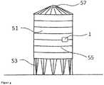
- FIG. 4 shows exactly a level gauge 1, which is attached to a container 51, wherein the level gauge is designed and set up with a vibration generating device on a container wall 55 of the container 51 to produce vibration and / or sound pressure changes.
- the container stands on supports 53 and comprises a conical upper end 57. Between said supports and the conical upper end, the container wall 55 is cylindrical.
- FIG. 5 shows four level measuring devices 1, 1 ', 1 ", 1''', which are attached to a container 51, said level measuring devices are designed and set up, each with a vibration generating device on a container wall 55 of the container 51 vibration and / or sound pressure changes
- This container also rests on supports 53 and comprises a conical upper end 57. Between said supports and the cone-shaped upper end, the container wall 55 is cylindrically shaped
- the four level measuring devices 1, 1 ', 1 ", 1'" on one Container a more precise detection of the vibration and / or sound pressure changes is made possible, so that disturbances can be better compensated and a more accurate determination of the filling takes place.
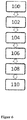
- FIG. 6 shows an example of a method for determining the level of a container with at least one level gauge, the method comprising the following steps: fixing 100 of the level gauge on the container by means of at least one holding magnet; Impact excitation 102 of a container wall of the container by at least one impact of the vibration generating device, wherein the at least one impact generates changes in vibration and / or sound pressure; Measuring 104 the said changes in vibration and / or sound pressure with the sound detection device, in particular with the striking mechanism, and converting 106 the vibration and / or sound pressure changes into analog and / or digital signals; wireless transmission 108 of the analogue and / or digital signals by the data transmission device to a data receiving device spaced from the at least one level measuring device; Calculation 110 of a level based on the analog and / or digital signals by the data receiving device.
- FIG. 7 shows a container 51 with the adhesive level gauge 1, said level gauge 1 is directly via a data transmission device with a data receiving device 29 via a wireless communication path 31 in contact.
- FIG. 8 shows a container 51 with the adhering level measuring device 1, said level measuring device 1 via a data transmission device with a data receiving device 29 via a wireless connection path 33, 35 is indirectly in contact.
- the data transmission device contacts a mobile telephone 37 via a direct wireless connection path 33, wherein the mobile telephone 37 contacts the data reception device 29 via a further direct wireless connection path 35.
Landscapes
- Physics & Mathematics (AREA)
- Acoustics & Sound (AREA)
- Electromagnetism (AREA)
- Thermal Sciences (AREA)
- Fluid Mechanics (AREA)
- General Physics & Mathematics (AREA)
- Measurement Of Levels Of Liquids Or Fluent Solid Materials (AREA)
Priority Applications (2)
| Application Number | Priority Date | Filing Date | Title |
|---|---|---|---|
| EP17195994.3A EP3470802B1 (fr) | 2017-10-11 | 2017-10-11 | Dispositif de mesure de niveau de remplissage et procédé pour déterminer la quantité de matière en vrac dans un récipient |
| PCT/EP2018/077613 WO2019072923A2 (fr) | 2017-10-11 | 2018-10-10 | Dispositif de mesure de niveau et procédé de détermination du niveau d'un réservoir |
Applications Claiming Priority (1)
| Application Number | Priority Date | Filing Date | Title |
|---|---|---|---|
| EP17195994.3A EP3470802B1 (fr) | 2017-10-11 | 2017-10-11 | Dispositif de mesure de niveau de remplissage et procédé pour déterminer la quantité de matière en vrac dans un récipient |
Publications (2)
| Publication Number | Publication Date |
|---|---|
| EP3470802A1 true EP3470802A1 (fr) | 2019-04-17 |
| EP3470802B1 EP3470802B1 (fr) | 2021-03-10 |
Family
ID=60083149
Family Applications (1)
| Application Number | Title | Priority Date | Filing Date |
|---|---|---|---|
| EP17195994.3A Active EP3470802B1 (fr) | 2017-10-11 | 2017-10-11 | Dispositif de mesure de niveau de remplissage et procédé pour déterminer la quantité de matière en vrac dans un récipient |
Country Status (2)
| Country | Link |
|---|---|
| EP (1) | EP3470802B1 (fr) |
| WO (1) | WO2019072923A2 (fr) |
Families Citing this family (3)
| Publication number | Priority date | Publication date | Assignee | Title |
|---|---|---|---|---|
| US11566936B1 (en) | 2016-02-12 | 2023-01-31 | Munters Corporation | Method and apparatus to non-intrusively measure the weight of loose bulk material within a rigid containing structure |
| CN114474393B (zh) * | 2021-12-31 | 2024-01-19 | 三一汽车制造有限公司 | 料仓料位监控方法、装置及搅拌站 |
| DE102024127387A1 (de) * | 2024-09-23 | 2026-03-26 | Diehl Ako Stiftung & Co. Kg | Schallbasierter Füllstandssensor |
Citations (8)
| Publication number | Priority date | Publication date | Assignee | Title |
|---|---|---|---|---|
| US3498500A (en) * | 1968-02-13 | 1970-03-03 | Xerox Corp | Level sensor |
| EP0009252A1 (fr) | 1978-09-26 | 1980-04-02 | Siemens Aktiengesellschaft | Dispositif pour la mesure du niveau de remplissage d'un réservoir rempli au moins partiellement d'un liquide |
| US4589077A (en) | 1983-07-27 | 1986-05-13 | Southwest Pump Company | Liquid level and volume measuring method and apparatus |
| DE10008093A1 (de) | 2000-02-22 | 2001-09-06 | Ifm Electronic Gmbh | Kapazitives Füllstandsmessgerät |
| DE202006009381U1 (de) | 2006-06-14 | 2007-07-19 | Pfister, Andreas | Kapazitive Füllstandsmessvorrichtung für Schüttgüter |
| WO2009047310A1 (fr) | 2007-10-09 | 2009-04-16 | Delox Elektronik Gmbh | Dispositif de mesure de niveau de remplissage pour silos flexibles |
| US20100206066A1 (en) * | 2007-06-21 | 2010-08-19 | Feldt & Meiton Marin Ab | Device and Method for Determination Regarding the Liquid Level in Containers |
| US20140366619A1 (en) * | 2001-06-22 | 2014-12-18 | Young Engineering & Manufacturing, Inc. | Acoustic volume indicator |
-
2017
- 2017-10-11 EP EP17195994.3A patent/EP3470802B1/fr active Active
-
2018
- 2018-10-10 WO PCT/EP2018/077613 patent/WO2019072923A2/fr not_active Ceased
Patent Citations (8)
| Publication number | Priority date | Publication date | Assignee | Title |
|---|---|---|---|---|
| US3498500A (en) * | 1968-02-13 | 1970-03-03 | Xerox Corp | Level sensor |
| EP0009252A1 (fr) | 1978-09-26 | 1980-04-02 | Siemens Aktiengesellschaft | Dispositif pour la mesure du niveau de remplissage d'un réservoir rempli au moins partiellement d'un liquide |
| US4589077A (en) | 1983-07-27 | 1986-05-13 | Southwest Pump Company | Liquid level and volume measuring method and apparatus |
| DE10008093A1 (de) | 2000-02-22 | 2001-09-06 | Ifm Electronic Gmbh | Kapazitives Füllstandsmessgerät |
| US20140366619A1 (en) * | 2001-06-22 | 2014-12-18 | Young Engineering & Manufacturing, Inc. | Acoustic volume indicator |
| DE202006009381U1 (de) | 2006-06-14 | 2007-07-19 | Pfister, Andreas | Kapazitive Füllstandsmessvorrichtung für Schüttgüter |
| US20100206066A1 (en) * | 2007-06-21 | 2010-08-19 | Feldt & Meiton Marin Ab | Device and Method for Determination Regarding the Liquid Level in Containers |
| WO2009047310A1 (fr) | 2007-10-09 | 2009-04-16 | Delox Elektronik Gmbh | Dispositif de mesure de niveau de remplissage pour silos flexibles |
Also Published As
| Publication number | Publication date |
|---|---|
| EP3470802B1 (fr) | 2021-03-10 |
| WO2019072923A3 (fr) | 2019-06-06 |
| WO2019072923A2 (fr) | 2019-04-18 |
Similar Documents
| Publication | Publication Date | Title |
|---|---|---|
| EP2659238B1 (fr) | Dispositif pour aligner un appareil de mesure | |
| EP2041529B1 (fr) | Dispositif pour déterminer et/ou surveiller une variable de processus d'un milieu | |
| DE1648514C3 (de) | Verfahren zum Überprüfen des Er haltungszustandes eines eingebauten Leitungsmastes aus Holz | |
| EP0903563B1 (fr) | Dispositif pour la détection et/ou la surveillance d'un niveau prédéterminé dans un récipient | |
| DE2906704A1 (de) | Ultraschalltransponder | |
| DE3044430C2 (de) | Verfahren und Vorrichtung zur Bestimmung des Elastizitätsmoduls E' (ω) und des Verlustmoduls E" (ω) eines visko-elastischen Materials | |
| EP3470802B1 (fr) | Dispositif de mesure de niveau de remplissage et procédé pour déterminer la quantité de matière en vrac dans un récipient | |
| DE2933618C2 (fr) | ||
| EP1373841A1 (fr) | Dispositif pour la determination ou la surveillance d'un niveau de remplissage predefini dans un contenant | |
| EP2729781A1 (fr) | Procédé de contrôle de mise sous vide | |
| DE3348119C2 (en) | Device for ascertaining and/or monitoring a predetermined filling level in a container | |
| WO2007137647A1 (fr) | Détermination de la hauteur d'un amortisseur pneumatique selon un procédé de mesure du temps de parcours d'une impulsion | |
| DE102009047728A1 (de) | Vorrichtung und Verfahren zur Bestimmung mindestens zweier Prozessgrößen eines flüssigen und/oder gasförmigen Mediums in einem Behälter | |
| EP3208587B1 (fr) | Capteur raccorde | |
| DE10154872A1 (de) | Meßverfahren und Meßvorrichtung zum Bestimmen der Masse und/oder des Schwerpunktes eines Bauteils | |
| WO2002012834A1 (fr) | Dispositif pour mesurer/determiner une grandeur physique d'un support | |
| EP2104078B1 (fr) | Détecteur de fumée | |
| CA1130441A (fr) | Jauge du niveau pour reservoir de liquide | |
| DE102020116149A1 (de) | Ermittlung des füllstands in einem fluidbehälter | |
| DE102021130597A1 (de) | Autarker Füllstandsensor mit Schwimmer, Verfahren zum Messen eines Füllstandes und Anordnung | |
| DE102010063146A1 (de) | Vorrichtung zur Bestimmung mindestens einer Prozessgröße und Verfahren zur Druckmessung mit einer derartigen Vorrichtung | |
| DE102007003104B4 (de) | Vorrichtung zur Bestimmung und/oder Überwachung von Prozessgrößen | |
| DE102010028161B4 (de) | Verfahren und Vorrichtung zur Bestimmung und/oder Überwachung eines Grenzfüllstands | |
| DE10153937A1 (de) | Vorrichtung zur Feststellung und/oder Überwachung eines vorbestimmten Füllstandes in einem Behälter | |
| DE102020112366A1 (de) | Anordnung eines Sensors zur Erfassung eines Füllstandes oder Grenzstandes an einer Haltevorrichtung, Verfahren zum Ermitteln eines Füllstands von Schüttgut |
Legal Events
| Date | Code | Title | Description |
|---|---|---|---|
| PUAI | Public reference made under article 153(3) epc to a published international application that has entered the european phase |
Free format text: ORIGINAL CODE: 0009012 |
|
| STAA | Information on the status of an ep patent application or granted ep patent |
Free format text: STATUS: REQUEST FOR EXAMINATION WAS MADE |
|
| 17P | Request for examination filed |
Effective date: 20181203 |
|
| AK | Designated contracting states |
Kind code of ref document: A1 Designated state(s): AL AT BE BG CH CY CZ DE DK EE ES FI FR GB GR HR HU IE IS IT LI LT LU LV MC MK MT NL NO PL PT RO RS SE SI SK SM TR |
|
| AX | Request for extension of the european patent |
Extension state: BA ME |
|
| GRAJ | Information related to disapproval of communication of intention to grant by the applicant or resumption of examination proceedings by the epo deleted |
Free format text: ORIGINAL CODE: EPIDOSDIGR1 |
|
| GRAP | Despatch of communication of intention to grant a patent |
Free format text: ORIGINAL CODE: EPIDOSNIGR1 |
|
| GRAP | Despatch of communication of intention to grant a patent |
Free format text: ORIGINAL CODE: EPIDOSNIGR1 |
|
| STAA | Information on the status of an ep patent application or granted ep patent |
Free format text: STATUS: GRANT OF PATENT IS INTENDED |
|
| INTG | Intention to grant announced |
Effective date: 20200403 |
|
| GRAS | Grant fee paid |
Free format text: ORIGINAL CODE: EPIDOSNIGR3 |
|
| GRAA | (expected) grant |
Free format text: ORIGINAL CODE: 0009210 |
|
| STAA | Information on the status of an ep patent application or granted ep patent |
Free format text: STATUS: THE PATENT HAS BEEN GRANTED |
|
| AK | Designated contracting states |
Kind code of ref document: B1 Designated state(s): AL AT BE BG CH CY CZ DE DK EE ES FI FR GB GR HR HU IE IS IT LI LT LU LV MC MK MT NL NO PL PT RO RS SE SI SK SM TR |
|
| REG | Reference to a national code |
Ref country code: GB Ref legal event code: FG4D Free format text: NOT ENGLISH |
|
| REG | Reference to a national code |
Ref country code: AT Ref legal event code: REF Ref document number: 1370328 Country of ref document: AT Kind code of ref document: T Effective date: 20210315 Ref country code: CH Ref legal event code: EP |
|
| REG | Reference to a national code |
Ref country code: IE Ref legal event code: FG4D Free format text: LANGUAGE OF EP DOCUMENT: GERMAN |
|
| REG | Reference to a national code |
Ref country code: DE Ref legal event code: R096 Ref document number: 502017009640 Country of ref document: DE |
|
| REG | Reference to a national code |
Ref country code: LT Ref legal event code: MG9D |
|
| PG25 | Lapsed in a contracting state [announced via postgrant information from national office to epo] |
Ref country code: BG Free format text: LAPSE BECAUSE OF FAILURE TO SUBMIT A TRANSLATION OF THE DESCRIPTION OR TO PAY THE FEE WITHIN THE PRESCRIBED TIME-LIMIT Effective date: 20210610 Ref country code: LT Free format text: LAPSE BECAUSE OF FAILURE TO SUBMIT A TRANSLATION OF THE DESCRIPTION OR TO PAY THE FEE WITHIN THE PRESCRIBED TIME-LIMIT Effective date: 20210310 Ref country code: HR Free format text: LAPSE BECAUSE OF FAILURE TO SUBMIT A TRANSLATION OF THE DESCRIPTION OR TO PAY THE FEE WITHIN THE PRESCRIBED TIME-LIMIT Effective date: 20210310 Ref country code: FI Free format text: LAPSE BECAUSE OF FAILURE TO SUBMIT A TRANSLATION OF THE DESCRIPTION OR TO PAY THE FEE WITHIN THE PRESCRIBED TIME-LIMIT Effective date: 20210310 Ref country code: GR Free format text: LAPSE BECAUSE OF FAILURE TO SUBMIT A TRANSLATION OF THE DESCRIPTION OR TO PAY THE FEE WITHIN THE PRESCRIBED TIME-LIMIT Effective date: 20210611 Ref country code: NO Free format text: LAPSE BECAUSE OF FAILURE TO SUBMIT A TRANSLATION OF THE DESCRIPTION OR TO PAY THE FEE WITHIN THE PRESCRIBED TIME-LIMIT Effective date: 20210610 |
|
| REG | Reference to a national code |
Ref country code: NL Ref legal event code: MP Effective date: 20210310 |
|
| PG25 | Lapsed in a contracting state [announced via postgrant information from national office to epo] |
Ref country code: SE Free format text: LAPSE BECAUSE OF FAILURE TO SUBMIT A TRANSLATION OF THE DESCRIPTION OR TO PAY THE FEE WITHIN THE PRESCRIBED TIME-LIMIT Effective date: 20210310 Ref country code: RS Free format text: LAPSE BECAUSE OF FAILURE TO SUBMIT A TRANSLATION OF THE DESCRIPTION OR TO PAY THE FEE WITHIN THE PRESCRIBED TIME-LIMIT Effective date: 20210310 Ref country code: LV Free format text: LAPSE BECAUSE OF FAILURE TO SUBMIT A TRANSLATION OF THE DESCRIPTION OR TO PAY THE FEE WITHIN THE PRESCRIBED TIME-LIMIT Effective date: 20210310 |
|
| PG25 | Lapsed in a contracting state [announced via postgrant information from national office to epo] |
Ref country code: NL Free format text: LAPSE BECAUSE OF FAILURE TO SUBMIT A TRANSLATION OF THE DESCRIPTION OR TO PAY THE FEE WITHIN THE PRESCRIBED TIME-LIMIT Effective date: 20210310 |
|
| PG25 | Lapsed in a contracting state [announced via postgrant information from national office to epo] |
Ref country code: SM Free format text: LAPSE BECAUSE OF FAILURE TO SUBMIT A TRANSLATION OF THE DESCRIPTION OR TO PAY THE FEE WITHIN THE PRESCRIBED TIME-LIMIT Effective date: 20210310 Ref country code: CZ Free format text: LAPSE BECAUSE OF FAILURE TO SUBMIT A TRANSLATION OF THE DESCRIPTION OR TO PAY THE FEE WITHIN THE PRESCRIBED TIME-LIMIT Effective date: 20210310 Ref country code: EE Free format text: LAPSE BECAUSE OF FAILURE TO SUBMIT A TRANSLATION OF THE DESCRIPTION OR TO PAY THE FEE WITHIN THE PRESCRIBED TIME-LIMIT Effective date: 20210310 |
|
| PG25 | Lapsed in a contracting state [announced via postgrant information from national office to epo] |
Ref country code: IS Free format text: LAPSE BECAUSE OF FAILURE TO SUBMIT A TRANSLATION OF THE DESCRIPTION OR TO PAY THE FEE WITHIN THE PRESCRIBED TIME-LIMIT Effective date: 20210710 Ref country code: PT Free format text: LAPSE BECAUSE OF FAILURE TO SUBMIT A TRANSLATION OF THE DESCRIPTION OR TO PAY THE FEE WITHIN THE PRESCRIBED TIME-LIMIT Effective date: 20210712 Ref country code: PL Free format text: LAPSE BECAUSE OF FAILURE TO SUBMIT A TRANSLATION OF THE DESCRIPTION OR TO PAY THE FEE WITHIN THE PRESCRIBED TIME-LIMIT Effective date: 20210310 Ref country code: RO Free format text: LAPSE BECAUSE OF FAILURE TO SUBMIT A TRANSLATION OF THE DESCRIPTION OR TO PAY THE FEE WITHIN THE PRESCRIBED TIME-LIMIT Effective date: 20210310 Ref country code: SK Free format text: LAPSE BECAUSE OF FAILURE TO SUBMIT A TRANSLATION OF THE DESCRIPTION OR TO PAY THE FEE WITHIN THE PRESCRIBED TIME-LIMIT Effective date: 20210310 |
|
| REG | Reference to a national code |
Ref country code: DE Ref legal event code: R097 Ref document number: 502017009640 Country of ref document: DE |
|
| PLBE | No opposition filed within time limit |
Free format text: ORIGINAL CODE: 0009261 |
|
| STAA | Information on the status of an ep patent application or granted ep patent |
Free format text: STATUS: NO OPPOSITION FILED WITHIN TIME LIMIT |
|
| PG25 | Lapsed in a contracting state [announced via postgrant information from national office to epo] |
Ref country code: ES Free format text: LAPSE BECAUSE OF FAILURE TO SUBMIT A TRANSLATION OF THE DESCRIPTION OR TO PAY THE FEE WITHIN THE PRESCRIBED TIME-LIMIT Effective date: 20210310 Ref country code: AL Free format text: LAPSE BECAUSE OF FAILURE TO SUBMIT A TRANSLATION OF THE DESCRIPTION OR TO PAY THE FEE WITHIN THE PRESCRIBED TIME-LIMIT Effective date: 20210310 Ref country code: DK Free format text: LAPSE BECAUSE OF FAILURE TO SUBMIT A TRANSLATION OF THE DESCRIPTION OR TO PAY THE FEE WITHIN THE PRESCRIBED TIME-LIMIT Effective date: 20210310 |
|
| 26N | No opposition filed |
Effective date: 20211213 |
|
| PG25 | Lapsed in a contracting state [announced via postgrant information from national office to epo] |
Ref country code: SI Free format text: LAPSE BECAUSE OF FAILURE TO SUBMIT A TRANSLATION OF THE DESCRIPTION OR TO PAY THE FEE WITHIN THE PRESCRIBED TIME-LIMIT Effective date: 20210310 |
|
| PG25 | Lapsed in a contracting state [announced via postgrant information from national office to epo] |
Ref country code: IT Free format text: LAPSE BECAUSE OF FAILURE TO SUBMIT A TRANSLATION OF THE DESCRIPTION OR TO PAY THE FEE WITHIN THE PRESCRIBED TIME-LIMIT Effective date: 20210310 |
|
| REG | Reference to a national code |
Ref country code: CH Ref legal event code: PL |
|
| PG25 | Lapsed in a contracting state [announced via postgrant information from national office to epo] |
Ref country code: IS Free format text: LAPSE BECAUSE OF FAILURE TO SUBMIT A TRANSLATION OF THE DESCRIPTION OR TO PAY THE FEE WITHIN THE PRESCRIBED TIME-LIMIT Effective date: 20210710 |
|
| REG | Reference to a national code |
Ref country code: BE Ref legal event code: MM Effective date: 20211031 |
|
| PG25 | Lapsed in a contracting state [announced via postgrant information from national office to epo] |
Ref country code: MC Free format text: LAPSE BECAUSE OF FAILURE TO SUBMIT A TRANSLATION OF THE DESCRIPTION OR TO PAY THE FEE WITHIN THE PRESCRIBED TIME-LIMIT Effective date: 20210310 |
|
| PG25 | Lapsed in a contracting state [announced via postgrant information from national office to epo] |
Ref country code: LU Free format text: LAPSE BECAUSE OF NON-PAYMENT OF DUE FEES Effective date: 20211011 Ref country code: BE Free format text: LAPSE BECAUSE OF NON-PAYMENT OF DUE FEES Effective date: 20211031 |
|
| PG25 | Lapsed in a contracting state [announced via postgrant information from national office to epo] |
Ref country code: LI Free format text: LAPSE BECAUSE OF NON-PAYMENT OF DUE FEES Effective date: 20211031 Ref country code: CH Free format text: LAPSE BECAUSE OF NON-PAYMENT OF DUE FEES Effective date: 20211031 |
|
| PG25 | Lapsed in a contracting state [announced via postgrant information from national office to epo] |
Ref country code: IE Free format text: LAPSE BECAUSE OF NON-PAYMENT OF DUE FEES Effective date: 20211011 |
|
| PG25 | Lapsed in a contracting state [announced via postgrant information from national office to epo] |
Ref country code: CY Free format text: LAPSE BECAUSE OF FAILURE TO SUBMIT A TRANSLATION OF THE DESCRIPTION OR TO PAY THE FEE WITHIN THE PRESCRIBED TIME-LIMIT Effective date: 20210310 |
|
| PG25 | Lapsed in a contracting state [announced via postgrant information from national office to epo] |
Ref country code: HU Free format text: LAPSE BECAUSE OF FAILURE TO SUBMIT A TRANSLATION OF THE DESCRIPTION OR TO PAY THE FEE WITHIN THE PRESCRIBED TIME-LIMIT; INVALID AB INITIO Effective date: 20171011 |
|
| REG | Reference to a national code |
Ref country code: AT Ref legal event code: MM01 Ref document number: 1370328 Country of ref document: AT Kind code of ref document: T Effective date: 20221011 |
|
| PG25 | Lapsed in a contracting state [announced via postgrant information from national office to epo] |
Ref country code: AT Free format text: LAPSE BECAUSE OF NON-PAYMENT OF DUE FEES Effective date: 20221011 |
|
| PG25 | Lapsed in a contracting state [announced via postgrant information from national office to epo] |
Ref country code: MK Free format text: LAPSE BECAUSE OF FAILURE TO SUBMIT A TRANSLATION OF THE DESCRIPTION OR TO PAY THE FEE WITHIN THE PRESCRIBED TIME-LIMIT Effective date: 20210310 |
|
| PG25 | Lapsed in a contracting state [announced via postgrant information from national office to epo] |
Ref country code: MT Free format text: LAPSE BECAUSE OF FAILURE TO SUBMIT A TRANSLATION OF THE DESCRIPTION OR TO PAY THE FEE WITHIN THE PRESCRIBED TIME-LIMIT Effective date: 20210310 |
|
| PG25 | Lapsed in a contracting state [announced via postgrant information from national office to epo] |
Ref country code: TR Free format text: LAPSE BECAUSE OF FAILURE TO SUBMIT A TRANSLATION OF THE DESCRIPTION OR TO PAY THE FEE WITHIN THE PRESCRIBED TIME-LIMIT Effective date: 20210310 |
|
| PGFP | Annual fee paid to national office [announced via postgrant information from national office to epo] |
Ref country code: DE Payment date: 20251028 Year of fee payment: 9 |
|
| PGFP | Annual fee paid to national office [announced via postgrant information from national office to epo] |
Ref country code: GB Payment date: 20251023 Year of fee payment: 9 |
|
| PGFP | Annual fee paid to national office [announced via postgrant information from national office to epo] |
Ref country code: FR Payment date: 20251027 Year of fee payment: 9 |