EP3470826B1 - Système de suivi des anodes utilisées dans les procédés électrolytiques - Google Patents
Système de suivi des anodes utilisées dans les procédés électrolytiques Download PDFInfo
- Publication number
- EP3470826B1 EP3470826B1 EP16903013.7A EP16903013A EP3470826B1 EP 3470826 B1 EP3470826 B1 EP 3470826B1 EP 16903013 A EP16903013 A EP 16903013A EP 3470826 B1 EP3470826 B1 EP 3470826B1
- Authority
- EP
- European Patent Office
- Prior art keywords
- anode
- station
- anodes
- image capture
- monitoring system
- Prior art date
- Legal status (The legal status is an assumption and is not a legal conclusion. Google has not performed a legal analysis and makes no representation as to the accuracy of the status listed.)
- Active
Links
Images

Classifications
-
- C—CHEMISTRY; METALLURGY
- C25—ELECTROLYTIC OR ELECTROPHORETIC PROCESSES; APPARATUS THEREFOR
- C25C—PROCESSES FOR THE ELECTROLYTIC PRODUCTION, RECOVERY OR REFINING OF METALS; APPARATUS THEREFOR
- C25C7/00—Constructional parts, or assemblies thereof, of cells; Servicing or operating of cells
- C25C7/06—Operating or servicing
-
- G—PHYSICS
- G01—MEASURING; TESTING
- G01N—INVESTIGATING OR ANALYSING MATERIALS BY DETERMINING THEIR CHEMICAL OR PHYSICAL PROPERTIES
- G01N21/00—Investigating or analysing materials by the use of optical means, i.e. using sub-millimetre waves, infrared, visible or ultraviolet light
- G01N21/84—Systems specially adapted for particular applications
- G01N21/88—Investigating the presence of flaws or contamination
- G01N21/95—Investigating the presence of flaws or contamination characterised by the material or shape of the object to be examined
-
- G—PHYSICS
- G01—MEASURING; TESTING
- G01N—INVESTIGATING OR ANALYSING MATERIALS BY DETERMINING THEIR CHEMICAL OR PHYSICAL PROPERTIES
- G01N21/00—Investigating or analysing materials by the use of optical means, i.e. using sub-millimetre waves, infrared, visible or ultraviolet light
- G01N21/84—Systems specially adapted for particular applications
- G01N21/88—Investigating the presence of flaws or contamination
- G01N21/8851—Scan or image signal processing specially adapted therefor, e.g. for scan signal adjustment, for detecting different kinds of defects, for compensating for structures, markings, edges
Definitions
- the present invention relates to a system for monitoring the anodes used in electrolytic processes, which enables the changes the anode undergoes during said processes to be known and the conditioning thereof to be optimized.
- Metals such as zinc can be obtained by means of electrolysis processes.
- Electrolysis generally refers to the decomposition of chemical substances by means of electrical current. The designation, however, also applies to certain processes that use electrical current to obtain chemical compounds.
- the electrodes that receive the metallic deposit make up the cathodes, while the sheets or plates of metal on which the sediments and impurities are deposited are called anodes.
- the anode found in electrolytic processes comprises a flat anodic plate of a certain thickness, on the surface of which a series of plastic insulators are distributed in order to avoid short circuits due to contact between plates, as well as plastic separators that facilitate the introduction of the anodes in the electrolytic tanks.
- the anode and cathode electrodes are arranged one after the other in parallel at a certain distance.
- the electrical current flows from anode to cathode through the electrolyte and enters the system through the positive terminal such that the anodes are those that introduce the current into the system, passing the current through the electrolyte solution and exiting through the cathodes.
- the electrodes When inside the tank, the electrodes must maintain the necessary distance between each other in order to guarantee operating conditions.
- Direct contact between anodes and cathodes may occur when the electrodes are removed from or introduced into the tanks.
- the installation of insulators is anticipated in order to maintain a certain distance between the electrodes in some anode models. Insulators made of a dielectric material resistant to the acid environment ensure adequate separation between the electrodes.
- the anodes Due to the environment and the type of cleaning to which the anodes are subjected, the deterioration thereof is remarkable, which is evidenced in the loss of dimension experienced by the material, the wear, loss and soiling of the insulators and plastic separators. Furthermore, once subjected to successive cycles of electrolysis and conditioning, and favored by their high weight, the anodes can change their dimensions, more particularly their longitudinal dimensions. When the anode sheet is lengthened longitudinally, it can reach the bottom of the tank, where, over time, the sludge from the separation of impurities from the anodes themselves has accumulated. If at a certain point in time the anode sheets reach the level of sludge and come into contact with it, a short circuit may occur.
- Verification on the anodic plates can be carried out by means of visual inspection by specialized operators who separate the worn plates for reconditioning or permanent removal. This visual inspection is unreliable in that the assessment depends on the professional criteria of the operator, in addition to being time-consuming and difficult to standardize.
- Anode monitoring systems by means of systematized processes are also known.
- the patent document with publication number US2009136122 describes a system for inspecting anodes comprising an image capture system for obtaining images of one side of the anode and a data processor for obtaining anode characteristics based on the extracted data.
- This system which only has one image capture system, does not obtain all the possible information on the anode, making it impossible to improve the method to the fullest possible extent.
- the object is achieved by the monitoring system for anodes used in an electrolytic process as defined in claim 1.
- the inventors have found a system for monitoring anodes that enables the automatic processing of the reconditioning of the anodes that have been used in electrolytic tanks. By monitoring the evolution of the anode and the possible deterioration thereof, it enables the relationship of the anode with the electrolytic process to be studied and the conditioning of the anodes to be optimized.
- the deterioration of the anodes is manifested by: loss of material from the anodic plate; longitudinal lengthening of the anodic plate; wear, dirt and loss of insulators that prevent short circuits due to contact between plates; wear and loss of the plastic separators that make it easier to insert the anodes into the electrolytic tanks and loss of flatness of the anodic plate.
- the dirt deposited on the insulators is a direct consequence of the gradual lengthening of the anodic plate. Said lengthening causes the position of these insulators to be variable, reducing the efficiency of the conditioning elements used to clean the anodic plates.
- the performance of the electrolytic process benefits from the system of the present invention that enables the correct alignment of the conditioning elements used for cleaning, ensuring proper cleaning of the insulators.
- the assembly of the anodes that are to be conditioned is housed in a transfer wagon, which transports the anodes from the electrolytic tank for their sequential treatment in a scrubbing station, a tampering station and an inspection station.
- the anodes have a remotely detectable information support, which stores the identification of the anode.
- the anode If, once the anode has been inspected, it complies with the conditions for reuse, the anode is transported back to the electrolytic tank housed in the transfer wagon. If it does not comply with the conditions for reuse, the anode is taken by the transfer wagon to a rejection station, the main function of which is replacing those anodes that are marked as faulty by the inspection station.
- the system is equipped with: a weighing system, an image capture system and an anode tracking system, a control unit connected to the image capture system and the weighing system, a recording unit and a lifting system.
- the weighing system collects the data for determining anode weight loss.
- the weighing system is carried out by means of an assembly of load cells and transmitting equipment for processing and converting the signal generated by said assembly into a standardized proportional format that enables connection thereof directly to a control unit.
- the image capture system which collects information from each face of the anode, comprises at least one first image capture device facing the first face of the anodic plate and at least one second image capture device facing the second face of the anodic plate, in order to capture successive digitized images of successive horizontal strips of the respective faces of the anodic plate when there is a relative displacement between said image capture devices and the anodic plate.
- the image capture system is a laser triangulation system.
- the tracking system of the invention is intended to control at all times the location and the characteristics of the anode in the electrolytic process.
- the tracking system enables each anode to be unequivocally distinguished and the results of the measurements of the system to be linked thereto.
- the tracking system is an RFID antenna and an RFID reader complementary to a Tag located on the anode.
- the control unit is connected to the anode image capture, weighing and tracking systems. Said unit is provided with comparing means for comparing captured parameters of each image, with reference parameters of at least one digitized reference image of the faces of an intact anodic plate, comprised in the memory means. In a similar way, it is possible to compare whether the weight of the anode falls within the range defined by the maximum and minimum weight parameters of an anodic reference plate for the electrolytic process.
- the reference parameters are selected from first parameters identifying the positions of the insulators on the reference plate; second parameters identifying the dimensions of each intact insulator; third parameters identifying the length of the reference plate; fourth parameters identifying the state of the surface of the reference plate; fifth parameters identifying the contour of the reference plate; sixth parameters identifying each of the intact separators; seventh parameters identifying the weight of the anodic reference plate and combinations of these identifying parameters.
- the comparison of the measurements made with the first identifying parameters it enables the lack of one or more insulators on the inspected anodic plate to be detected; with the second identifying parameters it enables breakages and excessive wear of one or more insulators in the inspected anodic plate to be detected; with the third parameters it enables an excessive elongation of the inspected anodic plate to be detected; with the fourth it enables parameter breakages, material faults, waste deposits and flatness defects to be detected on the inspected anodic plate; with the fifth parameters it enables deficiencies in the edges of the inspected anodic plate to be detected; with the sixth parameters it enables breakages, wear or lack of separators of the inspected anodic plate to be detected; with the seventh identifying parameters it enables the material decrease of the anodic plate.
- the recording unit of the system stores on a memory device the dimensional and weight measurements that characterize each anode, which enables the variation thereof to be observed over time and evaluate the effect that variations of the electrolytic process or of the reconditioning can have on the deterioration of the anodic sheet.
- the system can also comprise captured image filing means and image processing means connected to the comparing means to include, in each image captured of a complete anodic plate, an identification of at least a lack of compliance through the captured image of at least one reference parameter type that has been detected by the comparing means, and display means, such as for example a screen, to display each image captured of the complete anodic plate that includes said identification.
- an aspect of the invention relates to a monitoring system for electrodes used in electrolytic processes of the type having an inspection station, a scrubbing station and a tampering station characterized in that:
- the system comprises a rejection unit, which comprises an autonomous system, preferably a robot, the main function of which is replacing those anodes that are marked as faulty by the inspection station.
- a rejection unit which comprises an autonomous system, preferably a robot, the main function of which is replacing those anodes that are marked as faulty by the inspection station.
- the stations are located on frames.
- the lifting system that the stations have is embodied by a trolley actuated by a geared motor controlled by a inverter with braking resistors and has a holding brake.
- the position of the trolley is controlled by means of an encoder, as well as detectors at specific points.
- the system includes, in the frame of the inspection station, an assembly of load cells located such that they support the anode lifting system. By subtracting the weight of the lifting system (tare), it is possible to obtain that of the inspected anode. Additionally, transmitting equipment carries out the processing and conversion of the signal generated by said cells, into a standardized proportional format that enables connection thereof directly to a control unit.
- air is blown on the surface of the anode in order to remove the droplets of water that may remain on the surface of the anode as a result of the prior conditioning thereof in the scrubbing and tampering stations and can disrupt the inspection of the surface. More preferably, the blowing is carried out by means of air knives.
- FIG. 1 shows a perspective view of the monitoring system of the invention.
- FIG. 1 shows the scrubbing station (1), the tampering station (2), the inspection station (3) to where the anodes are transported housed in a transfer wagon (4).
- the anode (5) is provided with conventional insulators (5.1), on both faces thereof.
- the head of the anode is bar shaped with ends that project from the side edges of the anode plate.
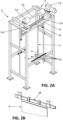
- FIG. 2A shows the anode in the inspection station. Said station comprises a frame (6) with four vertical columns joined together by rails and cross beams.
- a lifting system (7) is mounted on the upper portion of the frame (6) to lift and lower the anode (5) such that it moves vertically between the respective image capture devices (not shown) on two longitudinal support bars.
- the lifting device (7) comprises a motor group (7.1) that drives a transverse driving shaft (7.2) wherein at least two winding devices (7.3) of at least one cable (7.4) are mounted with an end portion coupled to a securing device (8) coupled to the head of the anode (5).
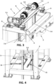
- FIG. 3 shows the position of the weighing system in the inspection system embodied in four shear load cells (9) located on the frame (6) and located such that they support the lifting device (7).
- the signal from each one of the cells is connected as an infeed to a balanced summing box, the outfeed of which is the only signal that is connected to transmitting equipment equipped with a high resolution analog-to-digital converter, appropriate for the relationship between the weight of the anode and the tare in which a signal is generated in a standardized proportional format that enables the direct connection thereof to the control unit.
- the tracking system in the inspection station is made up of a RFID antenna and a RFID reader.
- the RFID antenna is located on the frame at a distance suitable for detecting the Tag (10) on the anode, which has a unique code that is used as an identification key for the corresponding electrode.
- the reading of said code in coordination with the control unit, enables the recording unit to store all the measurements carried out by the system, associating them to an electrode characterized by said unique code.
- the identification Tag (10) is placed on the upper portion of the head of the anode, as shown in FIG. 2B . To do so, the head on the upper portion is machined and a plastic stopper is placed that separates the Tag (10) 5mm from the metal on the lower portion to ensure a correct reading.
- the Tag (10) is first positioned and then surrounded by a non-conducting, resin type material such that the Tag (10) is sufficiently separated from the metal.
- the image capture system not shown, in a particular embodiment has four identical laser triangulation equipment, mounted on the frame (6) of the inspection station, arranged so that 2 pairs of these pieces of equipment serve to inspect both faces of the anode.
- Each one of the pieces of equipment has a horizontal laser source and the pair located on each side has an opening sufficient to include the inspection of the width of the anodes.
- the inspection is carried out during the vertical movement of the anodes, which the lifting system (7) carries out integrated in the frame (6) of the inspection station.
- a signal is received from the transducer of the position of the lifting system (7) (encoder), to synchronize the acquisitions of the image capture system with the movement of the anode (5).
- Each laser triangular equipment is complemented with a vertical line laser that, in combination with the horizontal triangulations, enables the complete shape of the surface and the real and apparent dimensions of the anode to be obtained, real being understood as that corresponding to the development of the surface after the flattening thereof, and apparent being that which would be seen with a 2D camera.
- This measurement enables the possible oscillation of the anode during the vertical lifting movement to be compensated and enables the flatness of the anode to be measured accurately.
- air is blown on the surface of the anode using air knives (11) in order to remove the droplets of water that may remain on the surface of the anode (5) as a result of the prior conditioning thereof in the scrubbing (1) and tampering (2) stations.
- This blowing actuates due to a pneumatically operated high-flow valve, based on a solenoid valve controlled by the control unit.
- the drying of the anode removes the disruption that the water droplets suppose for the inspection.
- the scrubbing station (1) there is an assembly of brushes, one per insulator, the specific function of which is to clean the dirt deposited on said insulators.
- This assembly of brushes is mounted on two frames connected by means of both pneumatic cylinders. Each one of the rotating brushes is individually actuated by means of pneumatic motors.
- the lifting system is identical for all the stations and is actuated by an electric motor controlled by an inverter and likewise equipped with a position transducer (encoder).
Landscapes
- Chemical & Material Sciences (AREA)
- Biochemistry (AREA)
- General Physics & Mathematics (AREA)
- Physics & Mathematics (AREA)
- Health & Medical Sciences (AREA)
- Life Sciences & Earth Sciences (AREA)
- General Health & Medical Sciences (AREA)
- Analytical Chemistry (AREA)
- Engineering & Computer Science (AREA)
- Pathology (AREA)
- Immunology (AREA)
- Computer Vision & Pattern Recognition (AREA)
- Signal Processing (AREA)
- Chemical Kinetics & Catalysis (AREA)
- Electrochemistry (AREA)
- Materials Engineering (AREA)
- Metallurgy (AREA)
- Organic Chemistry (AREA)
- Electrolytic Production Of Metals (AREA)
Claims (5)
- Système de surveillance pour des anodes utilisées dans un processus électrolytique du type comprenant : un poste d'inspection (3) ; un poste de récurage (1) et un poste d'altération (2) ;
le système de surveillance comprend en outre :- un wagon de transfert qui est configuré pour transporter les anodes logées dans le wagon de transfert depuis un réservoir électrolytique pour un traitement séquentiel dans le poste de récurage (1), le poste d'altération (2) et le poste d'inspection (3) ;- dans lequel le système de surveillance est configuré de telle sorte que, une fois l'anode inspectée, si elle est conforme aux conditions de réutilisation, l'anode est transportée à nouveau dans le réservoir électrolytique logé dans le wagon de transfert, et si elle n'est pas conforme aux conditions de réutilisation, l'anode est acheminée par le wagon de transfert vers un poste de mise au rebut et- dans lequel le poste d'inspection (3) de la surface des anodes (5) et des éléments isolants (5.1) de celles-ci qui se trouvent sur ladite surface comprend à son tour :a) un système de pesage qui a un ensemble de cellules de pesée (9) et un équipement de transmission pour transmettre les informations à une unité de commande ;b) un système de suivi d'anode ;c) un système de capture d'image ;d) une unité de commande connectée au système de capture d'image, de pesage et de suivi d'anode dotée de moyens pour comparer les paramètres capturés par le système de capture d'image et de pesage avec des paramètres de référence ;e) une unité d'enregistrement qui traite et stocke les données capturées ;f) un système de levage d'anode etg) des moyens de soufflage d'anode (11) ; et- dans lequel le poste de récurage (1) comprend à son tour : un système de levage d'anode avec des moyens de commande de la position dans lequel les moyens de commande de la position reçoivent des informations concernant la position des isolateurs provenant de l'unité de commande. - Système de surveillance selon la revendication 1, caractérisé en ce que le système de suivi d'anode comprend une antenne RFID et un lecteur RFID complémentaire d'une étiquette (10) située sur l'anode.
- Système de surveillance selon l'une quelconque des revendications 1 et 2, caractérisé en ce que le poste d'inspection est situé sur un châssis et l'ensemble de cellules de pesée est situé sur le châssis supportant un système de levage d'anode (7).
- Système de surveillance selon l'une quelconque des revendications 1 à 3, caractérisé en ce que le système de capture d'image est un équipement de triangulation laser.
- Système de surveillance selon l'une quelconque des revendications 1 à 4, caractérisé en ce que le système comprend une unité de mise au rebut, qui comprend un robot en tant que système autonome pour remplacer les anodes qui sont marquées comme étant défectueuses par le poste d'inspection.
Applications Claiming Priority (1)
| Application Number | Priority Date | Filing Date | Title |
|---|---|---|---|
| PCT/ES2016/070398 WO2017203069A1 (fr) | 2016-05-26 | 2016-05-26 | Système de suivi des anodes utilisées dans les procédés électrolytiques |
Publications (4)
| Publication Number | Publication Date |
|---|---|
| EP3470826A1 EP3470826A1 (fr) | 2019-04-17 |
| EP3470826A4 EP3470826A4 (fr) | 2020-05-06 |
| EP3470826C0 EP3470826C0 (fr) | 2024-08-28 |
| EP3470826B1 true EP3470826B1 (fr) | 2024-08-28 |
Family
ID=60411982
Family Applications (1)
| Application Number | Title | Priority Date | Filing Date |
|---|---|---|---|
| EP16903013.7A Active EP3470826B1 (fr) | 2016-05-26 | 2016-05-26 | Système de suivi des anodes utilisées dans les procédés électrolytiques |
Country Status (4)
| Country | Link |
|---|---|
| EP (1) | EP3470826B1 (fr) |
| MX (1) | MX381363B (fr) |
| RU (1) | RU2704395C1 (fr) |
| WO (1) | WO2017203069A1 (fr) |
Families Citing this family (1)
| Publication number | Priority date | Publication date | Assignee | Title |
|---|---|---|---|---|
| CN115271626A (zh) * | 2022-03-28 | 2022-11-01 | 杭州三耐环保科技股份有限公司 | 一种用于电解生产的异常监控方法 |
Family Cites Families (7)
| Publication number | Priority date | Publication date | Assignee | Title |
|---|---|---|---|---|
| US4175021A (en) * | 1978-03-06 | 1979-11-20 | C. E. Equipment Co., Inc. | Apparatus for preventing end effect in anodes |
| CA1183066A (fr) * | 1982-06-17 | 1985-02-26 | Cominco Ltd. | Dispositif de brossage d'electrodes |
| ES2107328B1 (es) * | 1993-09-24 | 1998-05-16 | Asturiana De Zinc Sa | Procedimiento y maquina para la limpieza de anodos de cubas electroliticas. |
| JP4308992B2 (ja) * | 1999-09-30 | 2009-08-05 | 日鉱金属株式会社 | アノード重量測定装置 |
| US8594417B2 (en) * | 2007-11-27 | 2013-11-26 | Alcoa Inc. | Systems and methods for inspecting anodes and smelting management relating to the same |
| WO2012168498A1 (fr) * | 2011-06-08 | 2012-12-13 | Zincobre Ingeniería, S.L.U. | Installation pour la préparation superficielle d'anodes de réduction électrolytique |
| WO2012168501A1 (fr) * | 2011-06-10 | 2012-12-13 | Zincobre Ingeniería, S.L.U. | Système de vérification de la qualité d'anodes utilisées dans des procédés électrolytiques |
-
2016
- 2016-05-26 EP EP16903013.7A patent/EP3470826B1/fr active Active
- 2016-05-26 MX MX2017000942A patent/MX381363B/es unknown
- 2016-05-26 RU RU2018146188A patent/RU2704395C1/ru active
- 2016-05-26 WO PCT/ES2016/070398 patent/WO2017203069A1/fr not_active Ceased
Also Published As
| Publication number | Publication date |
|---|---|
| EP3470826C0 (fr) | 2024-08-28 |
| EP3470826A1 (fr) | 2019-04-17 |
| MX2017000942A (es) | 2018-06-18 |
| MX381363B (es) | 2025-03-12 |
| RU2704395C1 (ru) | 2019-10-28 |
| EP3470826A4 (fr) | 2020-05-06 |
| WO2017203069A1 (fr) | 2017-11-30 |
Similar Documents
| Publication | Publication Date | Title |
|---|---|---|
| FI125211B (en) | A method of measuring and arranging an electric current flowing at a single electrode of an electrolysis system | |
| US8594417B2 (en) | Systems and methods for inspecting anodes and smelting management relating to the same | |
| FI125515B (en) | A method of measuring and arranging an electric current flowing at a single electrode of an electrolysis system | |
| JP6081462B2 (ja) | 相互接続された電解セル内の電流分布を連続的に検出するための常設システム | |
| CN102598392A (zh) | 电池的运行方法 | |
| CN118671636B (zh) | 电池检测装置、电池检测方法和系统 | |
| EP3470826A1 (fr) | Système de suivi des anodes utilisées dans les procédés électrolytiques | |
| CN119782915B (zh) | 一种基于大数据的集装箱码头可视化理货方法 | |
| CN109250411A (zh) | 一种电极自动化运输系统 | |
| JPH10245690A (ja) | 電解製錬の異常検出方法及びそれを実施する異常検出システム | |
| CN102279139A (zh) | 铝电解电容器用阳极电子铝箔表面溶解度的检测方法及其测试水溶液 | |
| CN114622251A (zh) | 一种电解生产中短路异常的处理方法和系统 | |
| EP3460106B1 (fr) | Grue auxiliaire automatique pour la maintenance d'une installation d'électrolyse | |
| CN217399012U (zh) | 一种电解短路自动处理装置 | |
| WO2012168501A1 (fr) | Système de vérification de la qualité d'anodes utilisées dans des procédés électrolytiques | |
| JPH10195688A (ja) | 電解製錬の異常検出方法及びそれを実施する異常検出システム | |
| KR20080058988A (ko) | 교량의 안전 점검장치 | |
| CN112935498B (zh) | 一种轨道车辆铝合金型材检验试样制备系统及方法 | |
| Makipaa et al. | Ir-based method for copper electrolysis short circuit detection | |
| CN218213339U (zh) | 一种方形电池在线短路测试装置 | |
| CN117787770A (zh) | 一种电力物资抽检和配送管理系统及方法 | |
| Filzwieser et al. | Geometric surface inspection for stainless steel cathode plates and copper cathodes | |
| FI125909B (en) | Arrangement for measuring the current flowing at a single electrode of an electrolysis system | |
| JP2025150835A (ja) | 電池交換装置 | |
| WO2014076374A1 (fr) | Agencement pour surveiller une distribution de courant dans une cellule électrolytique |
Legal Events
| Date | Code | Title | Description |
|---|---|---|---|
| STAA | Information on the status of an ep patent application or granted ep patent |
Free format text: STATUS: THE INTERNATIONAL PUBLICATION HAS BEEN MADE |
|
| PUAI | Public reference made under article 153(3) epc to a published international application that has entered the european phase |
Free format text: ORIGINAL CODE: 0009012 |
|
| STAA | Information on the status of an ep patent application or granted ep patent |
Free format text: STATUS: REQUEST FOR EXAMINATION WAS MADE |
|
| 17P | Request for examination filed |
Effective date: 20181221 |
|
| AK | Designated contracting states |
Kind code of ref document: A1 Designated state(s): AL AT BE BG CH CY CZ DE DK EE ES FI FR GB GR HR HU IE IS IT LI LT LU LV MC MK MT NL NO PL PT RO RS SE SI SK SM TR |
|
| AX | Request for extension of the european patent |
Extension state: BA ME |
|
| DAV | Request for validation of the european patent (deleted) | ||
| DAX | Request for extension of the european patent (deleted) | ||
| A4 | Supplementary search report drawn up and despatched |
Effective date: 20200402 |
|
| RIC1 | Information provided on ipc code assigned before grant |
Ipc: C25C 7/06 20060101ALI20200328BHEP Ipc: G01N 21/95 20060101AFI20200328BHEP Ipc: G01N 21/88 20060101ALI20200328BHEP |
|
| RAP1 | Party data changed (applicant data changed or rights of an application transferred) |
Owner name: ZINCOBRE INGENIERIA, S.L. |
|
| RIN1 | Information on inventor provided before grant (corrected) |
Inventor name: LEFEVRE, YVES |
|
| STAA | Information on the status of an ep patent application or granted ep patent |
Free format text: STATUS: EXAMINATION IS IN PROGRESS |
|
| 17Q | First examination report despatched |
Effective date: 20211220 |
|
| GRAP | Despatch of communication of intention to grant a patent |
Free format text: ORIGINAL CODE: EPIDOSNIGR1 |
|
| STAA | Information on the status of an ep patent application or granted ep patent |
Free format text: STATUS: GRANT OF PATENT IS INTENDED |
|
| INTG | Intention to grant announced |
Effective date: 20240415 |
|
| GRAS | Grant fee paid |
Free format text: ORIGINAL CODE: EPIDOSNIGR3 |
|
| GRAA | (expected) grant |
Free format text: ORIGINAL CODE: 0009210 |
|
| STAA | Information on the status of an ep patent application or granted ep patent |
Free format text: STATUS: THE PATENT HAS BEEN GRANTED |
|
| AK | Designated contracting states |
Kind code of ref document: B1 Designated state(s): AL AT BE BG CH CY CZ DE DK EE ES FI FR GB GR HR HU IE IS IT LI LT LU LV MC MK MT NL NO PL PT RO RS SE SI SK SM TR |
|
| REG | Reference to a national code |
Ref country code: GB Ref legal event code: FG4D |
|
| REG | Reference to a national code |
Ref country code: CH Ref legal event code: EP |
|
| REG | Reference to a national code |
Ref country code: DE Ref legal event code: R096 Ref document number: 602016089178 Country of ref document: DE |
|
| REG | Reference to a national code |
Ref country code: IE Ref legal event code: FG4D |
|
| U01 | Request for unitary effect filed |
Effective date: 20240927 |
|
| U07 | Unitary effect registered |
Designated state(s): AT BE BG DE DK EE FI FR IT LT LU LV MT NL PT RO SE SI Effective date: 20241024 |
|
| PG25 | Lapsed in a contracting state [announced via postgrant information from national office to epo] |
Ref country code: NO Free format text: LAPSE BECAUSE OF FAILURE TO SUBMIT A TRANSLATION OF THE DESCRIPTION OR TO PAY THE FEE WITHIN THE PRESCRIBED TIME-LIMIT Effective date: 20241128 |
|
| PG25 | Lapsed in a contracting state [announced via postgrant information from national office to epo] |
Ref country code: PL Free format text: LAPSE BECAUSE OF FAILURE TO SUBMIT A TRANSLATION OF THE DESCRIPTION OR TO PAY THE FEE WITHIN THE PRESCRIBED TIME-LIMIT Effective date: 20240828 Ref country code: GR Free format text: LAPSE BECAUSE OF FAILURE TO SUBMIT A TRANSLATION OF THE DESCRIPTION OR TO PAY THE FEE WITHIN THE PRESCRIBED TIME-LIMIT Effective date: 20241129 |
|
| PG25 | Lapsed in a contracting state [announced via postgrant information from national office to epo] |
Ref country code: IS Free format text: LAPSE BECAUSE OF FAILURE TO SUBMIT A TRANSLATION OF THE DESCRIPTION OR TO PAY THE FEE WITHIN THE PRESCRIBED TIME-LIMIT Effective date: 20241228 |
|
| PG25 | Lapsed in a contracting state [announced via postgrant information from national office to epo] |
Ref country code: HR Free format text: LAPSE BECAUSE OF FAILURE TO SUBMIT A TRANSLATION OF THE DESCRIPTION OR TO PAY THE FEE WITHIN THE PRESCRIBED TIME-LIMIT Effective date: 20240828 |
|
| PG25 | Lapsed in a contracting state [announced via postgrant information from national office to epo] |
Ref country code: RS Free format text: LAPSE BECAUSE OF FAILURE TO SUBMIT A TRANSLATION OF THE DESCRIPTION OR TO PAY THE FEE WITHIN THE PRESCRIBED TIME-LIMIT Effective date: 20241128 Ref country code: ES Free format text: LAPSE BECAUSE OF FAILURE TO SUBMIT A TRANSLATION OF THE DESCRIPTION OR TO PAY THE FEE WITHIN THE PRESCRIBED TIME-LIMIT Effective date: 20240828 |
|
| PG25 | Lapsed in a contracting state [announced via postgrant information from national office to epo] |
Ref country code: RS Free format text: LAPSE BECAUSE OF FAILURE TO SUBMIT A TRANSLATION OF THE DESCRIPTION OR TO PAY THE FEE WITHIN THE PRESCRIBED TIME-LIMIT Effective date: 20241128 Ref country code: PL Free format text: LAPSE BECAUSE OF FAILURE TO SUBMIT A TRANSLATION OF THE DESCRIPTION OR TO PAY THE FEE WITHIN THE PRESCRIBED TIME-LIMIT Effective date: 20240828 Ref country code: NO Free format text: LAPSE BECAUSE OF FAILURE TO SUBMIT A TRANSLATION OF THE DESCRIPTION OR TO PAY THE FEE WITHIN THE PRESCRIBED TIME-LIMIT Effective date: 20241128 Ref country code: IS Free format text: LAPSE BECAUSE OF FAILURE TO SUBMIT A TRANSLATION OF THE DESCRIPTION OR TO PAY THE FEE WITHIN THE PRESCRIBED TIME-LIMIT Effective date: 20241228 Ref country code: HR Free format text: LAPSE BECAUSE OF FAILURE TO SUBMIT A TRANSLATION OF THE DESCRIPTION OR TO PAY THE FEE WITHIN THE PRESCRIBED TIME-LIMIT Effective date: 20240828 Ref country code: GR Free format text: LAPSE BECAUSE OF FAILURE TO SUBMIT A TRANSLATION OF THE DESCRIPTION OR TO PAY THE FEE WITHIN THE PRESCRIBED TIME-LIMIT Effective date: 20241129 Ref country code: ES Free format text: LAPSE BECAUSE OF FAILURE TO SUBMIT A TRANSLATION OF THE DESCRIPTION OR TO PAY THE FEE WITHIN THE PRESCRIBED TIME-LIMIT Effective date: 20240828 |
|
| PG25 | Lapsed in a contracting state [announced via postgrant information from national office to epo] |
Ref country code: SM Free format text: LAPSE BECAUSE OF FAILURE TO SUBMIT A TRANSLATION OF THE DESCRIPTION OR TO PAY THE FEE WITHIN THE PRESCRIBED TIME-LIMIT Effective date: 20240828 |
|
| PG25 | Lapsed in a contracting state [announced via postgrant information from national office to epo] |
Ref country code: CZ Free format text: LAPSE BECAUSE OF FAILURE TO SUBMIT A TRANSLATION OF THE DESCRIPTION OR TO PAY THE FEE WITHIN THE PRESCRIBED TIME-LIMIT Effective date: 20240828 |
|
| PG25 | Lapsed in a contracting state [announced via postgrant information from national office to epo] |
Ref country code: SK Free format text: LAPSE BECAUSE OF FAILURE TO SUBMIT A TRANSLATION OF THE DESCRIPTION OR TO PAY THE FEE WITHIN THE PRESCRIBED TIME-LIMIT Effective date: 20240828 |
|
| U20 | Renewal fee for the european patent with unitary effect paid |
Year of fee payment: 10 Effective date: 20250409 |
|
| PLBE | No opposition filed within time limit |
Free format text: ORIGINAL CODE: 0009261 |
|
| STAA | Information on the status of an ep patent application or granted ep patent |
Free format text: STATUS: NO OPPOSITION FILED WITHIN TIME LIMIT |
|
| 26N | No opposition filed |
Effective date: 20250530 |
|
| REG | Reference to a national code |
Ref country code: CH Ref legal event code: H13 Free format text: ST27 STATUS EVENT CODE: U-0-0-H10-H13 (AS PROVIDED BY THE NATIONAL OFFICE) Effective date: 20251223 |
|
| PG25 | Lapsed in a contracting state [announced via postgrant information from national office to epo] |
Ref country code: CH Free format text: LAPSE BECAUSE OF NON-PAYMENT OF DUE FEES Effective date: 20250531 |
|
| GBPC | Gb: european patent ceased through non-payment of renewal fee |
Effective date: 20250526 |
|
| PG25 | Lapsed in a contracting state [announced via postgrant information from national office to epo] |
Ref country code: MC Free format text: LAPSE BECAUSE OF FAILURE TO SUBMIT A TRANSLATION OF THE DESCRIPTION OR TO PAY THE FEE WITHIN THE PRESCRIBED TIME-LIMIT Effective date: 20240828 |
|
| PG25 | Lapsed in a contracting state [announced via postgrant information from national office to epo] |
Ref country code: GB Free format text: LAPSE BECAUSE OF NON-PAYMENT OF DUE FEES Effective date: 20250526 |
|
| PG25 | Lapsed in a contracting state [announced via postgrant information from national office to epo] |
Ref country code: IE Free format text: LAPSE BECAUSE OF NON-PAYMENT OF DUE FEES Effective date: 20250526 |
|
| U20 | Renewal fee for the european patent with unitary effect paid |
Year of fee payment: 11 Effective date: 20260320 |