EP3470864A1 - Speisung einer spule für kernspintomografie - Google Patents
Speisung einer spule für kernspintomografie Download PDFInfo
- Publication number
- EP3470864A1 EP3470864A1 EP17196064.4A EP17196064A EP3470864A1 EP 3470864 A1 EP3470864 A1 EP 3470864A1 EP 17196064 A EP17196064 A EP 17196064A EP 3470864 A1 EP3470864 A1 EP 3470864A1
- Authority
- EP
- European Patent Office
- Prior art keywords
- body coil
- signal
- port
- ports
- feeding
- Prior art date
- Legal status (The legal status is an assumption and is not a legal conclusion. Google has not performed a legal analysis and makes no representation as to the accuracy of the status listed.)
- Withdrawn
Links
Images

Classifications
-
- G—PHYSICS
- G01—MEASURING; TESTING
- G01R—MEASURING ELECTRIC VARIABLES; MEASURING MAGNETIC VARIABLES
- G01R33/00—Arrangements or instruments for measuring magnetic variables
- G01R33/20—Arrangements or instruments for measuring magnetic variables involving magnetic resonance
- G01R33/28—Details of apparatus provided for in groups G01R33/44 - G01R33/64
- G01R33/32—Excitation or detection systems, e.g. using radio frequency signals
- G01R33/34—Constructional details, e.g. resonators, specially adapted to MR
- G01R33/34092—RF coils specially adapted for NMR spectrometers
-
- G—PHYSICS
- G01—MEASURING; TESTING
- G01R—MEASURING ELECTRIC VARIABLES; MEASURING MAGNETIC VARIABLES
- G01R33/00—Arrangements or instruments for measuring magnetic variables
- G01R33/20—Arrangements or instruments for measuring magnetic variables involving magnetic resonance
- G01R33/28—Details of apparatus provided for in groups G01R33/44 - G01R33/64
- G01R33/32—Excitation or detection systems, e.g. using radio frequency signals
- G01R33/36—Electrical details, e.g. matching or coupling of the coil to the receiver
- G01R33/3628—Tuning/matching of the transmit/receive coil
-
- A—HUMAN NECESSITIES
- A61—MEDICAL OR VETERINARY SCIENCE; HYGIENE
- A61B—DIAGNOSIS; SURGERY; IDENTIFICATION
- A61B5/00—Measuring for diagnostic purposes; Identification of persons
- A61B5/05—Detecting, measuring or recording for diagnosis by means of electric currents or magnetic fields; Measuring using microwaves or radio waves
- A61B5/055—Detecting, measuring or recording for diagnosis by means of electric currents or magnetic fields; Measuring using microwaves or radio waves involving electronic [EMR] or nuclear [NMR] magnetic resonance, e.g. magnetic resonance imaging
-
- G—PHYSICS
- G01—MEASURING; TESTING
- G01R—MEASURING ELECTRIC VARIABLES; MEASURING MAGNETIC VARIABLES
- G01R33/00—Arrangements or instruments for measuring magnetic variables
- G01R33/20—Arrangements or instruments for measuring magnetic variables involving magnetic resonance
- G01R33/28—Details of apparatus provided for in groups G01R33/44 - G01R33/64
- G01R33/32—Excitation or detection systems, e.g. using radio frequency signals
- G01R33/36—Electrical details, e.g. matching or coupling of the coil to the receiver
- G01R33/3614—RF power amplifiers
-
- G—PHYSICS
- G01—MEASURING; TESTING
- G01R—MEASURING ELECTRIC VARIABLES; MEASURING MAGNETIC VARIABLES
- G01R33/00—Arrangements or instruments for measuring magnetic variables
- G01R33/20—Arrangements or instruments for measuring magnetic variables involving magnetic resonance
- G01R33/28—Details of apparatus provided for in groups G01R33/44 - G01R33/64
- G01R33/32—Excitation or detection systems, e.g. using radio frequency signals
- G01R33/36—Electrical details, e.g. matching or coupling of the coil to the receiver
- G01R33/3621—NMR receivers or demodulators, e.g. preamplifiers, means for frequency modulation of the MR signal using a digital down converter, means for analog to digital conversion [ADC] or for filtering or processing of the MR signal such as bandpass filtering, resampling, decimation or interpolation
-
- G—PHYSICS
- G01—MEASURING; TESTING
- G01R—MEASURING ELECTRIC VARIABLES; MEASURING MAGNETIC VARIABLES
- G01R33/00—Arrangements or instruments for measuring magnetic variables
- G01R33/20—Arrangements or instruments for measuring magnetic variables involving magnetic resonance
- G01R33/28—Details of apparatus provided for in groups G01R33/44 - G01R33/64
- G01R33/32—Excitation or detection systems, e.g. using radio frequency signals
- G01R33/36—Electrical details, e.g. matching or coupling of the coil to the receiver
- G01R33/3664—Switching for purposes other than coil coupling or decoupling, e.g. switching between a phased array mode and a quadrature mode, switching between surface coil modes of different geometrical shapes, switching from a whole body reception coil to a local reception coil or switching for automatic coil selection in moving table MR or for changing the field-of-view
-
- G—PHYSICS
- G01—MEASURING; TESTING
- G01R—MEASURING ELECTRIC VARIABLES; MEASURING MAGNETIC VARIABLES
- G01R33/00—Arrangements or instruments for measuring magnetic variables
- G01R33/20—Arrangements or instruments for measuring magnetic variables involving magnetic resonance
- G01R33/28—Details of apparatus provided for in groups G01R33/44 - G01R33/64
- G01R33/32—Excitation or detection systems, e.g. using radio frequency signals
- G01R33/34—Constructional details, e.g. resonators, specially adapted to MR
- G01R33/34046—Volume type coils, e.g. bird-cage coils; Quadrature bird-cage coils; Circularly polarised coils
- G01R33/34076—Birdcage coils
Definitions
- the invention relates to the field of feeding a body coil for magnetic resonance imaging (MRI), and in particular to a system comprising a body coil for magnetic resonance imaging and an RF amplifier connected to the body coil for feeding the body coil with an RF signal is provided.
- the invention further relates to a method for feeding a body coil of a magnetic resonance imaging system with an RF signal by an RF amplifier
- an examination object in an MRI system, an examination object, usually a examination object, is exposed to a uniform main magnetic field (B 0 field) so that the magnetic moments of the nuclei within the examination object form a certain net magnetization of all nuclei parallel to the Bo field, which can be tilted leading to a rotation around the axis of the applied Bo field (Larmor precession).
- the rate of precession is called Larmor frequency which is dependent on the specific physical characteristics of the involved nuclei, namely their gyromagnetic ratio, and the strength of the applied B 0 field.
- the gyromagnetic ratio is the ratio between the magnetic moment and the spin of a nucleus.
- an RF excitation pulse (B 1 field) which has an orthogonal polarization to the Bo field, generated by means of an RF transmitting antenna or coil, and matching the Larmor frequency of the nuclei of interest, the spins of the nuclei can be excited and brought into phase, and a deflection of their net magnetization from the direction of the Bo field is obtained, so that a transversal component in relation to the longitudinal component of the net magnetization is generated.
- MR magnetic resonance
- the Larmor frequency of the nuclei Due to the fact that the Larmor frequency is dependent on the strength of the magnetic field which is imposed on the nuclei, the Larmor frequency of the nuclei accordingly decreases along and with the decreasing gradient (and vice versa) of the total, superimposed Bo field, so that by appropriately tuning the frequency of the transmitted RF excitation pulse (and by accordingly tuning the resonance frequency of the RF/MR receive antenna), and by accordingly controlling the gradient magnetic fields, a selection of nuclei within a slice at a certain location along each gradient in the x-, y- and z-direction, and by this, in total, within a certain voxel of the object can be obtained.
- the above described RF (transmitting and/or receiving) antennas can be provided in the form of so-called body coils which can be fixedly mounted within an examination space of an MRI system for imaging a whole examination object, or which are arranged directly on or around a local zone or area to be examined.
- the invention is about the feeding of such a body coil for MRI with RF excitation pulse (B 1 field).
- a body coil is a resonant antenna, designed for generating a well-defined magnetic field inside the human body.
- the power fed into a body coil is typically generated by pulsed amplifiers which demand a good or acceptable power matching at their output.
- 2-channel multi-transmit has become standard for 3T clinical systems in recent years.
- the two orthogonal modes of the RF body coil are fed individually by respective RF amplifiers.
- the driving ports for the coil modes are matched to increase the power efficiency of the amplifier.
- the body coil impedance, and thus the matching varies from examination object to examination object and/or imaging position. Conventionally, matching was optimized for a typical load, typically a heavy examination object, accepting inefficient use of RF power in other loading cases.
- US 2015/0028870 A1 describes a two-channel magnetic resonance tomography system with a regulation circuit for an amplification system in order to be able to take into account different load situations of the MRI system in a flexible manner. It is thus possible to improve the MRI measurements if the MRI system is set to the respective load situation beforehand by an idle state measurement. The adaptation may also be carried out during the MRI measurement. Therefore, a multiplicity of different load situations may be taken into account by the regulation circuit.
- a system comprising a body coil for magnetic resonance imaging and an RF amplifier connected to the body coil for feeding the body coil with an RF signal
- the body coil comprises two different ports for feeding the RF signal into the body coil
- the body coil is provided with a switch for selectively activating only one single port for feeding the RF signal to the body coil at a time
- the two ports are located at different locations of the body coil such that the dependence of the reflected part of the RF signal fed into the body coil from the weight of the examination object to which the body coil is applied is different for the two ports.
- the impedance of the body coil can be adapted to different loads of the examination object in an easy and reliable way.
- the reflected part of the RF signal fed into the body coil via a given port changes. Therefore, changing from one port to the other port for feeding the RF signal to the body coil may improve the MRI measurement. Hence, the total load range in which the power is efficiently used is increased.
- the body coil comprises two end rings comprised of two circular conductive loops which are connected with each other by a plurality of conductive straight rungs, one port being located at a rung and the other port being located at an end ring.
- the port which is located at a rung is located at the center of the rung in the middle between the two end rings.
- the port which is located at an end ring is preferably located at a ring-to-ground connection of the end ring.
- the switch for selectively activating only one single port for feeding the RF signal to the body coil at a time is comprised of separate lines leading from the RF amplifier to the different ports, respectively, wherein each line comprises a switching diode for opening or closing the connection of the RF amplifier with the body coil, respectively.
- Such lines and diodes may be integrated into the body coil.
- the switching functionality of the lines may be also integrated into feed cables for the body coil or be part of transmit receive switches of the body coil.
- the switching diode is preferably arranged between two pieces of lambda/4 cable in the lines. When biased, this deactivates the connected port and, thus, prevents power leakage.
- the system may comprise only one single RF amplifier.
- the system comprises a second RF amplifier.
- the second amplifier is connected to the body coil for feeding the body coil with an RF signal comprising a mode which is orthogonal to the mode of the RF signal of the other RF amplifier.
- the RF amplifier is preferably connected to the body coil in the same way as the other RF amplifier but offset by 90° around the central axis of the body coil.
- the preferred embodiments of the invention described above apply in the same way to the part of the system which is related to the second RF amplifier.
- the two ports are located at different locations of the body coil such that the dependence of the reflected part of the RF signal fed into the body coil from the weight of the examination object to which the body coil is applied is different for the two ports. This allows for adapting to different load situations due to different weights of the examination object. This difference of the dependence of the reflected part of the RF signal fed into the body coil from the weight of the examination object to which the body coil is applied can be realized in different ways.
- the function describing the dependence of the reflected part of the RF signal fed into the body coil from the weight of the examination object to which the body coil is applied for the two ports, respectively has a single minimum at a specific weight of the examination object, wherein the specific weight of the examination object defined by the minimum of the function is different for the two ports.
- the two ports may be related two different preferred load ranges, respectively, i.e. for higher weights and for lower weights of the examination objects, respectively, with a transition point between the ranges in which the respective impedances are the same for both ports.
- a system comprising a body coil for magnetic resonance imaging and an RF receiver connected to the body coil for receiving an RF signal from the body coil
- the body coil comprises two different ports for feeding the RF signal to the RF receiver
- the body coil is provided with a switch for selectively activating only one single port for feeding the RF signal from the body coil to the receiver at a time
- the two ports are located at different locations of the body coil such that the receiving characteristics of the RF signal is different for the two ports.
- the optimal power transfer from the body coil to the RF receiver and/or ideal noise matching is considered.
- a method for feeding a body coil of a magnetic resonance imaging system with an RF signal by an RF amplifier comprising the following steps:
- Preferred embodiments of this method relate to the preferred embodiments of the systems described before.
- the invention also relates to a method for feeding an RF signal from a body coil of a magnetic resonance imaging system to an RF receiver, wherein the body coil comprises two different ports for feeding the RF signal from the body coil to the RF receiver, the two ports being located at different locations of the body coil such that the dependence of the reflected part of the RF signal fed from the body coil from the weight of the examination object to which the body coil is applied is different for the two ports, the method comprising the following steps:
- the determination of receiving characteristics of the RF signal may be a RF measurement but can also be MR imaging based measurement taking in the order of seconds.
- the term "better receiving characteristics" refers to at least one predefined measurable value which is characteristic for the receiving of the RF signal and for which the better, i.e. the value with the higher amount can be determined. Examples for such values are power transfer from the body coil to the RF receiver and noise matching quality.
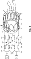
- Fig. 1 depicts a system comprising a body coil 9 for magnetic resonance imaging and two RF amplifiers 2, 3 connected to the body coil 9 for feeding the body coil 9 with two different RF signals
- the body coil 9 comprises two different ports 21, 22, and 31, 32 for each RF amplifier 2, 3, respectively, for feeding a respective RF signal into the body coil 9.
- the body coil 9 is provided with two switches for selectively activating only one single port 21 or 22 for the first RF amplifier 2 and 31 or 32 and the second amplifier 3, respectively, for feeding the RF signal to the body coil 9 at a time.
- switches are comprised of two separate lines 210, 220, 310, 320 leading from the RF amplifiers 2, 3 to the different ports 21, 22, 31, 32, respectively.
- Each line 210, 220, 310, 320 comprises a switching diode 215, 225, 315, 325 for opening or closing the connection of the RF amplifier 2, 3 with the body coil 9, respectively.
- the switching diodes 215, 225, 315, 325 are each arranged between two pieces of lambda/4 cable 214, 216, 224, 226, 314, 316, 324, 326. It is to be noted that in Fig. 1 DC supply of the switching diode 215, 225, 315, 325 and RF/DC blocks are not shown for simplicity of the drawing.
- the two ports 21, 22, 31, 32 for each RF amplifier 2, 3, respectively, are located at different locations of the body coil 9 such that the dependence of the reflected part of the RF signal fed into the body coil 9 from the weight of the examination object 1 to which the body coil 9 is applied is different for the two ports 21, 22, 31, 32 of each RF amplifier 2, 3, respectively.
- the body coil 9 comprises two end rings 11 which are comprised of two circular conductive loops which are connected with each other by a plurality of conductive straight rungs 12, one port 21, 31 of each RF amplifier 2, 3 being located at a rung 12, respectively, and the other port 22, 32 being located at an end ring 11 for each RF amplifier 2, 3, respectively.
- the ports 21, 31 which are located at one of the rungs 12 are located at the center of the rung 12 in the middle between the two end rings 11.
- the ports 22, 32 which is located at one of the end rings 12 is located at a ring-to-ground connection of the end ring 11.
- the RF amplifiers 2, 3 reach always drive the same linear modes, even though the feed is being connected at different locations. Only the matching differs for the two feeding locations.
- One pair of ports 21, 31 may be optimized for strong loading, whereas the other pair of ports 22, 32 may be optimized for weak loading.
- the functions describing the dependence of the reflected part of the RF signal fed into the body coil 9 from the weight of the examination object 1 to which the body coil 9 is applied for the two ports 21, 22, 31, 32 of each RF amplifier 2, 3, respectively, has a single minimum at a specific weight of the examination object 1, wherein the specific weight of the examination 1 object defined by the minimum of the function is different for the two ports 21, 22, 31, 32, respectively.
- Figs. 2a and 2b depict the conventional case with one single port and Fig. 2b depicts the case according to the preferred embodiment of the invention discussed here.
- the graphs of Figs. 2a and 2b show the dependence of the ratio R of reflected power to forwarded power from the weight W of the examination object 1 and, thus, the load due to the examination object 1.
- the vertical dashed line depicts the weight W T of a typical heavy loading patient as examination object. While in the conventional case, the function is optimized for a typical heavier examination object with weight W T , the design according to the preferred embodiment of the invention provides for a broader range with still acceptable reflected power.
- One port pair 21, 31 has a matching optimized for strong loading, while the other pair of ports 22, 32 is optimized for low loading. Depending on the actual coil loading, either one or the other pair of ports 21, 22, 31, 32 is used while the other one remains unused.
- the workflow according to the present embodiment of the invention is as follows: First, the examination object 1, i.e. a patient, is put into an imaging position. Then the shim set to be applied is determined which is a standard routine for MRI imaging. The next step is determining a port matching, which is a quick measurement within ms, and selecting the better matched port pair 21, 31, or 22, 32, respectively. Thereafter a MR sequence is applied for imaging.
- the examination object 1 i.e. a patient
- the shim set to be applied is determined which is a standard routine for MRI imaging.
- the next step is determining a port matching, which is a quick measurement within ms, and selecting the better matched port pair 21, 31, or 22, 32, respectively.
- a MR sequence is applied for imaging.
- This workflow may be part of a normal scan preparation phase where short (milliseconds) RF pulses are consecutively applied to each port 21, 22, 31, 32 and the reflected power at the terminals of the RF amplifiers 2, 3 is measured.
- a preparation phase software may select the best pair with lowest power reflection.
- the port selection may run autonomously, e.g. as part of the RF amplifier functionality.
- the RF amplifiers 2, 3 continuously tests the individual ports 21, 22, 31, 32 regularly and select the most convenient.
- An interrupt logic line to the data acquisition system may prevent that testing and selection happens during scanning and in-between scans intended to have identical RF settings.
- the preferred embodiment her is described for the transmitting case (TX). Respective techniques may also be applied for the receiving case (RX).
- RX the design of the embodiment is the same as depicted in Fig. 1 , reference signs 2 and 3 relating then to RF receivers. Optimal pairs of ports 21, 22, 31, 32 for TX and RX are not necessarily the same.
- REFERENCE SYMBOL LIST examination object 1 RF amplifier 2 RF amplifier 3 body coil 9 end rings 11 rungs 12 port 21 port 22 port 31 port 32 line 210 lambda/4 cable 214 switching diode 215 lambda/4 cable 216 line 220 lambda/4 cable 224 switching diode 225 lambda/4 cable 226 line 310 lambda/4 cable 314 switching diode 315 lambda/4 cable 316 line 320 lambda/4 cable 324 switching diode 325 lambda/4 cable 326
Landscapes
- Physics & Mathematics (AREA)
- Health & Medical Sciences (AREA)
- General Physics & Mathematics (AREA)
- Condensed Matter Physics & Semiconductors (AREA)
- Life Sciences & Earth Sciences (AREA)
- Nuclear Medicine, Radiotherapy & Molecular Imaging (AREA)
- Heart & Thoracic Surgery (AREA)
- Surgery (AREA)
- Engineering & Computer Science (AREA)
- Biomedical Technology (AREA)
- Biophysics (AREA)
- Medical Informatics (AREA)
- Molecular Biology (AREA)
- Pathology (AREA)
- Animal Behavior & Ethology (AREA)
- General Health & Medical Sciences (AREA)
- Public Health (AREA)
- Veterinary Medicine (AREA)
- Radiology & Medical Imaging (AREA)
- High Energy & Nuclear Physics (AREA)
- Magnetic Resonance Imaging Apparatus (AREA)
Priority Applications (6)
| Application Number | Priority Date | Filing Date | Title |
|---|---|---|---|
| EP17196064.4A EP3470864A1 (de) | 2017-10-12 | 2017-10-12 | Speisung einer spule für kernspintomografie |
| CN201880065848.9A CN111201446B (zh) | 2017-10-12 | 2018-09-26 | 对用于磁共振成像的线圈进行馈送 |
| US16/754,789 US11099249B2 (en) | 2017-10-12 | 2018-09-26 | Feeding a coil for magnetic resonance imaging |
| EP18778471.5A EP3695239B1 (de) | 2017-10-12 | 2018-09-26 | Speisung einer spule für kernspintomografie |
| JP2020520215A JP7076539B2 (ja) | 2017-10-12 | 2018-09-26 | 磁気共鳴イメージング用のコイルの給電 |
| PCT/EP2018/076059 WO2019072555A1 (en) | 2017-10-12 | 2018-09-26 | POWERING A COIL FOR MAGNETIC RESONANCE IMAGING |
Applications Claiming Priority (1)
| Application Number | Priority Date | Filing Date | Title |
|---|---|---|---|
| EP17196064.4A EP3470864A1 (de) | 2017-10-12 | 2017-10-12 | Speisung einer spule für kernspintomografie |
Publications (1)
| Publication Number | Publication Date |
|---|---|
| EP3470864A1 true EP3470864A1 (de) | 2019-04-17 |
Family
ID=60083178
Family Applications (2)
| Application Number | Title | Priority Date | Filing Date |
|---|---|---|---|
| EP17196064.4A Withdrawn EP3470864A1 (de) | 2017-10-12 | 2017-10-12 | Speisung einer spule für kernspintomografie |
| EP18778471.5A Active EP3695239B1 (de) | 2017-10-12 | 2018-09-26 | Speisung einer spule für kernspintomografie |
Family Applications After (1)
| Application Number | Title | Priority Date | Filing Date |
|---|---|---|---|
| EP18778471.5A Active EP3695239B1 (de) | 2017-10-12 | 2018-09-26 | Speisung einer spule für kernspintomografie |
Country Status (5)
| Country | Link |
|---|---|
| US (1) | US11099249B2 (de) |
| EP (2) | EP3470864A1 (de) |
| JP (1) | JP7076539B2 (de) |
| CN (1) | CN111201446B (de) |
| WO (1) | WO2019072555A1 (de) |
Citations (6)
| Publication number | Priority date | Publication date | Assignee | Title |
|---|---|---|---|---|
| WO2012093321A1 (en) * | 2011-01-06 | 2012-07-12 | Koninklijke Philips Electronics N.V. | Multi-channel transmit mr imaging |
| WO2012143833A1 (en) * | 2011-04-21 | 2012-10-26 | Koninklijke Philips Electronics N.V. | Multichannel rf volume resonator for mri |
| WO2013171611A1 (en) * | 2012-05-14 | 2013-11-21 | Koninklijke Philips N.V. | Feeding circuit arrangement for supplying a radio frequency signal to a plurality of coil elements of a magnetic resonance coil system |
| US20140320130A1 (en) * | 2013-04-25 | 2014-10-30 | Jürgen Nistler | Antenna Array for a Magnetic Resonance Tomography System |
| US20150002156A1 (en) * | 2012-01-17 | 2015-01-01 | Koninklijke Philips N.V. | Multi-resonant t/r antenna for mr image generation |
| US20150028870A1 (en) | 2011-10-06 | 2015-01-29 | Chih-Chung Chen | Two-Channel Magnetic Resonance Imaging |
Family Cites Families (39)
| Publication number | Priority date | Publication date | Assignee | Title |
|---|---|---|---|---|
| JP2001203540A (ja) * | 2000-01-19 | 2001-07-27 | Hitachi Ltd | 高周波電力増幅器 |
| US6316941B1 (en) * | 2000-02-24 | 2001-11-13 | Marconi Medical Systems, Inc. | Open view quadrature birdcage coil |
| AU2003302444A1 (en) * | 2002-11-27 | 2004-06-18 | Koninklijke Philips Electronics N.V. | Degenerate birdcage coil and transmit/receive apparatus and method for same |
| JP4349648B2 (ja) * | 2003-06-25 | 2009-10-21 | 株式会社日立メディコ | 磁気共鳴イメージング装置とその受信コイル |
| US20080262467A1 (en) * | 2005-02-16 | 2008-10-23 | Humphrey Joseph A C | Blood Flow Bypass Catheters and Methods for the Delivery of Medium to the Vasculature and Body Ducts |
| US7659719B2 (en) * | 2005-11-25 | 2010-02-09 | Mr Instruments, Inc. | Cavity resonator for magnetic resonance systems |
| JP5357010B2 (ja) * | 2006-04-24 | 2013-12-04 | コーニンクレッカ フィリップス エヌ ヴェ | コイルシステム及び磁気共鳴システム |
| CN101636664A (zh) * | 2007-03-20 | 2010-01-27 | 皇家飞利浦电子股份有限公司 | 磁共振成像系统和方法 |
| WO2008135888A1 (en) * | 2007-05-04 | 2008-11-13 | Koninklijke Philips Electronics N.V. | Method and multi-channel rf transmitter arrangement for generating rf fields |
| US8717021B2 (en) * | 2007-09-07 | 2014-05-06 | The Johns Hopkins University | SAR dosimeter for RF power deposition in MRI and methods and systems related thereto |
| US7977629B2 (en) * | 2007-09-26 | 2011-07-12 | M&M Mass Spec Consulting, LLC | Atmospheric pressure ion source probe for a mass spectrometer |
| US9515494B2 (en) * | 2008-09-27 | 2016-12-06 | Witricity Corporation | Wireless power system including impedance matching network |
| US8102177B2 (en) * | 2009-03-31 | 2012-01-24 | General Electric Company | Using S-parameter measurements to manage SAR and transmit gain in MRI |
| US8935223B2 (en) * | 2009-04-30 | 2015-01-13 | Oracle International Corporation | Structure of hierarchical compressed data structure for tabular data |
| US9274189B2 (en) * | 2009-11-30 | 2016-03-01 | Hitachi Medical Corporation | High-frequency coil unit and magnetic resonance imaging device |
| CN102958432B (zh) * | 2010-08-17 | 2015-06-10 | 株式会社日立医疗器械 | 高频线圈及使用了该高频线圈的磁共振摄像装置 |
| US8610638B2 (en) * | 2011-01-17 | 2013-12-17 | Nokia Corporation | FM transmission using a RFID/NFC coil antenna |
| JP5685476B2 (ja) * | 2011-04-11 | 2015-03-18 | 株式会社日立製作所 | 磁気共鳴イメージング装置 |
| US9116214B2 (en) * | 2011-05-31 | 2015-08-25 | General Electric Company | RF coil array having two or more switches built within each RF coil array element, compatible with both magnetic resonance and a temperature mapping |
| US9733324B2 (en) | 2011-07-04 | 2017-08-15 | Koninklijke Philips N.V. | Magnetic resonance imaging system with a multi-channel impedance matching network |
| JP2013175152A (ja) | 2012-01-24 | 2013-09-05 | Dexerials Corp | 透明導電性素子およびその製造方法、入力装置、電子機器、ならびに薄膜のパターニング方法 |
| CN103308874B (zh) * | 2012-03-06 | 2016-06-08 | 西门子(深圳)磁共振有限公司 | 射频线圈装置和磁共振成像系统 |
| CN104755950B (zh) | 2012-10-25 | 2019-03-22 | 皇家飞利浦有限公司 | 在磁共振(mr)成像系统中使用的具有单独控制的环形构件和横档的射频(rf)鸟笼式线圈 |
| JP6402112B2 (ja) * | 2012-11-01 | 2018-10-10 | コーニンクレッカ フィリップス エヌ ヴェKoninklijke Philips N.V. | 磁気共鳴イメージングのためのzセグメント化されたラジオ周波数アンテナ装置 |
| DE102013216859B4 (de) | 2013-08-23 | 2018-11-22 | Siemens Healthcare Gmbh | Magnetresonanzspule und damit arbeitendes Magnetresonanzgerät und Magnetresonanzsystem, sowie Verfahren zum Betrieb der Magnetresonanzspule |
| US9730643B2 (en) * | 2013-10-17 | 2017-08-15 | Siemens Healthcare Gmbh | Method and system for anatomical object detection using marginal space deep neural networks |
| JP6153905B2 (ja) * | 2014-09-05 | 2017-06-28 | 株式会社日立製作所 | 高周波コイルおよび磁気共鳴撮像装置 |
| US9107595B1 (en) * | 2014-09-29 | 2015-08-18 | The United States Of America As Represented By The Secretary Of The Army | Node excitation driving function measures for cerebral cortex network analysis of electroencephalograms |
| WO2016058841A1 (en) * | 2014-10-16 | 2016-04-21 | Koninklijke Philips N.V. | Mri birdcage coil with distributed excitation |
| US10390725B2 (en) * | 2015-02-17 | 2019-08-27 | Siemens Aktiengesellschaft | Connection of coils to an MR device |
| DE102015202861B4 (de) | 2015-02-17 | 2016-11-10 | Siemens Healthcare Gmbh | MR-Gerät mit Verteilernetzwerk |
| CN107430175B (zh) * | 2015-03-27 | 2020-04-21 | 皇家飞利浦有限公司 | 具有多个独立的发射接收信道的磁共振体积线圈及其操作方法 |
| US10534049B2 (en) * | 2015-04-30 | 2020-01-14 | Koninklijke Philips N.V. | Radio frequency volume coil with improved space and access for use in a magnetic resonance examination system |
| DE102016204620B4 (de) * | 2015-07-16 | 2019-07-04 | Siemens Healthcare Gmbh | MR-Körperspule |
| US11205848B2 (en) * | 2015-08-07 | 2021-12-21 | Nucurrent, Inc. | Method of providing a single structure multi mode antenna having a unitary body construction for wireless power transmission using magnetic field coupling |
| JP6461356B2 (ja) * | 2015-08-27 | 2019-01-30 | 株式会社日立製作所 | 高周波コイルおよび磁気共鳴撮像装置 |
| JP6590736B2 (ja) * | 2016-03-04 | 2019-10-16 | 株式会社日立製作所 | 高周波コイル及びそれを用いた磁気共鳴撮像装置 |
| JP7126452B2 (ja) * | 2016-04-04 | 2022-08-26 | コーニンクレッカ フィリップス エヌ ヴェ | 磁気共鳴イメージング装置のための選択可能な駆動ポートを有するrf送信システム |
| US10976388B2 (en) * | 2017-03-24 | 2021-04-13 | Quality Electrodynamics, Llc | Minimizing intravascular magnetic resonance imaging (MRI) guidewire heating with single layer MRI transmit/receive radio frequency coil |
-
2017
- 2017-10-12 EP EP17196064.4A patent/EP3470864A1/de not_active Withdrawn
-
2018
- 2018-09-26 CN CN201880065848.9A patent/CN111201446B/zh active Active
- 2018-09-26 EP EP18778471.5A patent/EP3695239B1/de active Active
- 2018-09-26 US US16/754,789 patent/US11099249B2/en active Active
- 2018-09-26 WO PCT/EP2018/076059 patent/WO2019072555A1/en not_active Ceased
- 2018-09-26 JP JP2020520215A patent/JP7076539B2/ja active Active
Patent Citations (6)
| Publication number | Priority date | Publication date | Assignee | Title |
|---|---|---|---|---|
| WO2012093321A1 (en) * | 2011-01-06 | 2012-07-12 | Koninklijke Philips Electronics N.V. | Multi-channel transmit mr imaging |
| WO2012143833A1 (en) * | 2011-04-21 | 2012-10-26 | Koninklijke Philips Electronics N.V. | Multichannel rf volume resonator for mri |
| US20150028870A1 (en) | 2011-10-06 | 2015-01-29 | Chih-Chung Chen | Two-Channel Magnetic Resonance Imaging |
| US20150002156A1 (en) * | 2012-01-17 | 2015-01-01 | Koninklijke Philips N.V. | Multi-resonant t/r antenna for mr image generation |
| WO2013171611A1 (en) * | 2012-05-14 | 2013-11-21 | Koninklijke Philips N.V. | Feeding circuit arrangement for supplying a radio frequency signal to a plurality of coil elements of a magnetic resonance coil system |
| US20140320130A1 (en) * | 2013-04-25 | 2014-10-30 | Jürgen Nistler | Antenna Array for a Magnetic Resonance Tomography System |
Also Published As
| Publication number | Publication date |
|---|---|
| EP3695239B1 (de) | 2023-07-12 |
| CN111201446B (zh) | 2023-04-04 |
| US20200309875A1 (en) | 2020-10-01 |
| US11099249B2 (en) | 2021-08-24 |
| JP7076539B2 (ja) | 2022-05-27 |
| EP3695239A1 (de) | 2020-08-19 |
| JP2020536644A (ja) | 2020-12-17 |
| WO2019072555A1 (en) | 2019-04-18 |
| CN111201446A (zh) | 2020-05-26 |
Similar Documents
| Publication | Publication Date | Title |
|---|---|---|
| EP2699924B1 (de) | Vielkanal radiofrequenz-volumenresonator für die bildgebende magnetische resonanz | |
| CN103703384B (zh) | 用于mri的感应耦合的局部并行发射线圈,其元件的每个都包括可变阻抗 | |
| US9880242B2 (en) | RF coil elements with split DC loops for magnetic resonance imaging systems for integrated parallel reception, excitation, and shimming and related methods and devices | |
| US10948557B2 (en) | MRI RF coil assemblies with RF coil elements that allow wireless communication data transmission and related methods and systems | |
| KR101887130B1 (ko) | 자기 공명 시스템의 제어를 위한 방법 | |
| CN107209235B (zh) | 多通道rf线圈组件的自动阻抗调节 | |
| US10557900B2 (en) | Body coil having a pre-amplification unit configured to provide a detuning effect | |
| CN103513200A (zh) | 磁共振设备的未连接的发射/接收线圈的自动失谐 | |
| EP2989478B1 (de) | Einzelkoaxialschnittstelle für magnetresonanzspulen | |
| JP2019513451A (ja) | 磁気共鳴イメージング装置のための選択可能な駆動ポートを有するrf送信システム | |
| US20190339345A1 (en) | Inductively feeding an rf coil for magnetic resonance imaging | |
| US20180031652A1 (en) | Magnetic resonance imaging apparatus and method with slice-specific adjustment of radio frequency pulses to current ambient conditions | |
| US10753995B2 (en) | System and method for simultaneous radio frequency transmission and reception in magnetic resonance imaging | |
| EP3695239B1 (de) | Speisung einer spule für kernspintomografie | |
| CN102879752B (zh) | 设计射频脉冲以减轻失谐的方法、处理器以及磁共振设备 | |
| US20250093446A1 (en) | Methods and apparatus for mobile mri employing a permanent magnet | |
| Niendorf | Multi-channel transmit/receive RF coil arrays for cardiac MRI at ultrahigh fields: Design, validation and clinical application | |
| Metzger et al. | Non-contrast enhanced renal MRA at 7 T |
Legal Events
| Date | Code | Title | Description |
|---|---|---|---|
| PUAI | Public reference made under article 153(3) epc to a published international application that has entered the european phase |
Free format text: ORIGINAL CODE: 0009012 |
|
| AK | Designated contracting states |
Kind code of ref document: A1 Designated state(s): AL AT BE BG CH CY CZ DE DK EE ES FI FR GB GR HR HU IE IS IT LI LT LU LV MC MK MT NL NO PL PT RO RS SE SI SK SM TR |
|
| AX | Request for extension of the european patent |
Extension state: BA ME |
|
| STAA | Information on the status of an ep patent application or granted ep patent |
Free format text: STATUS: THE APPLICATION IS DEEMED TO BE WITHDRAWN |
|
| 18D | Application deemed to be withdrawn |
Effective date: 20191018 |
|
| RAP1 | Party data changed (applicant data changed or rights of an application transferred) |
Owner name: KONINKLIJKE PHILIPS N.V. |