EP3471904B1 - Verfahren zur herstellung eines behälters - Google Patents
Verfahren zur herstellung eines behälters Download PDFInfo
- Publication number
- EP3471904B1 EP3471904B1 EP17730367.4A EP17730367A EP3471904B1 EP 3471904 B1 EP3471904 B1 EP 3471904B1 EP 17730367 A EP17730367 A EP 17730367A EP 3471904 B1 EP3471904 B1 EP 3471904B1
- Authority
- EP
- European Patent Office
- Prior art keywords
- container
- starting material
- receiving element
- processing region
- processing apparatus
- Prior art date
- Legal status (The legal status is an assumption and is not a legal conclusion. Google has not performed a legal analysis and makes no representation as to the accuracy of the status listed.)
- Active
Links
Images





Classifications
-
- B—PERFORMING OPERATIONS; TRANSPORTING
- B21—MECHANICAL METAL-WORKING WITHOUT ESSENTIALLY REMOVING MATERIAL; PUNCHING METAL
- B21D—WORKING OR PROCESSING OF SHEET METAL OR METAL TUBES, RODS OR PROFILES WITHOUT ESSENTIALLY REMOVING MATERIAL; PUNCHING METAL
- B21D51/00—Making hollow objects
- B21D51/16—Making hollow objects characterised by the use of the objects
- B21D51/52—Making hollow objects characterised by the use of the objects boxes, cigarette cases, or the like
-
- B—PERFORMING OPERATIONS; TRANSPORTING
- B21—MECHANICAL METAL-WORKING WITHOUT ESSENTIALLY REMOVING MATERIAL; PUNCHING METAL
- B21D—WORKING OR PROCESSING OF SHEET METAL OR METAL TUBES, RODS OR PROFILES WITHOUT ESSENTIALLY REMOVING MATERIAL; PUNCHING METAL
- B21D35/00—Combined processes according to or processes combined with methods covered by groups B21D1/00 - B21D31/00
- B21D35/001—Shaping combined with punching, e.g. stamping and perforating
-
- B—PERFORMING OPERATIONS; TRANSPORTING
- B21—MECHANICAL METAL-WORKING WITHOUT ESSENTIALLY REMOVING MATERIAL; PUNCHING METAL
- B21D—WORKING OR PROCESSING OF SHEET METAL OR METAL TUBES, RODS OR PROFILES WITHOUT ESSENTIALLY REMOVING MATERIAL; PUNCHING METAL
- B21D51/00—Making hollow objects
- B21D51/02—Making hollow objects characterised by the structure of the objects
- B21D51/04—Making hollow objects characterised by the structure of the objects built-up objects, e.g. objects with rigidly-attached bottom or cover
-
- B—PERFORMING OPERATIONS; TRANSPORTING
- B21—MECHANICAL METAL-WORKING WITHOUT ESSENTIALLY REMOVING MATERIAL; PUNCHING METAL
- B21D—WORKING OR PROCESSING OF SHEET METAL OR METAL TUBES, RODS OR PROFILES WITHOUT ESSENTIALLY REMOVING MATERIAL; PUNCHING METAL
- B21D51/00—Making hollow objects
- B21D51/16—Making hollow objects characterised by the use of the objects
-
- B—PERFORMING OPERATIONS; TRANSPORTING
- B65—CONVEYING; PACKING; STORING; HANDLING THIN OR FILAMENTARY MATERIAL
- B65B—MACHINES, APPARATUS OR DEVICES FOR, OR METHODS OF, PACKAGING ARTICLES OR MATERIALS; UNPACKING
- B65B23/00—Packaging fragile or shock-sensitive articles other than bottles; Unpacking eggs
-
- B—PERFORMING OPERATIONS; TRANSPORTING
- B65—CONVEYING; PACKING; STORING; HANDLING THIN OR FILAMENTARY MATERIAL
- B65B—MACHINES, APPARATUS OR DEVICES FOR, OR METHODS OF, PACKAGING ARTICLES OR MATERIALS; UNPACKING
- B65B41/00—Supplying or feeding container-forming sheets or wrapping material
- B65B41/12—Feeding webs from rolls
- B65B41/16—Feeding webs from rolls by rollers
-
- B—PERFORMING OPERATIONS; TRANSPORTING
- B65—CONVEYING; PACKING; STORING; HANDLING THIN OR FILAMENTARY MATERIAL
- B65B—MACHINES, APPARATUS OR DEVICES FOR, OR METHODS OF, PACKAGING ARTICLES OR MATERIALS; UNPACKING
- B65B47/00—Apparatus or devices for forming pockets or receptacles in or from sheets, blanks, or webs, comprising essentially a die into which the material is pressed or a folding die through which the material is moved
- B65B47/08—Apparatus or devices for forming pockets or receptacles in or from sheets, blanks, or webs, comprising essentially a die into which the material is pressed or a folding die through which the material is moved by application of fluid pressure
- B65B47/10—Apparatus or devices for forming pockets or receptacles in or from sheets, blanks, or webs, comprising essentially a die into which the material is pressed or a folding die through which the material is moved by application of fluid pressure by vacuum
-
- B—PERFORMING OPERATIONS; TRANSPORTING
- B65—CONVEYING; PACKING; STORING; HANDLING THIN OR FILAMENTARY MATERIAL
- B65B—MACHINES, APPARATUS OR DEVICES FOR, OR METHODS OF, PACKAGING ARTICLES OR MATERIALS; UNPACKING
- B65B55/00—Preserving, protecting or purifying packages or package contents in association with packaging
-
- B—PERFORMING OPERATIONS; TRANSPORTING
- B65—CONVEYING; PACKING; STORING; HANDLING THIN OR FILAMENTARY MATERIAL
- B65B—MACHINES, APPARATUS OR DEVICES FOR, OR METHODS OF, PACKAGING ARTICLES OR MATERIALS; UNPACKING
- B65B61/00—Auxiliary devices, not otherwise provided for, for operating on sheets, blanks, webs, binding material, containers or packages
-
- B—PERFORMING OPERATIONS; TRANSPORTING
- B65—CONVEYING; PACKING; STORING; HANDLING THIN OR FILAMENTARY MATERIAL
- B65B—MACHINES, APPARATUS OR DEVICES FOR, OR METHODS OF, PACKAGING ARTICLES OR MATERIALS; UNPACKING
- B65B9/00—Enclosing successive articles, or quantities of material, e.g. liquids or semiliquids, in flat, folded, or tubular webs of flexible sheet material; Subdividing filled flexible tubes to form packages
- B65B9/02—Enclosing successive articles, or quantities of material between opposed webs
- B65B9/04—Enclosing successive articles, or quantities of material between opposed webs one or both webs being formed with pockets for the reception of the articles, or of the quantities of material
- B65B9/045—Enclosing successive articles, or quantities of material between opposed webs one or both webs being formed with pockets for the reception of the articles, or of the quantities of material for single articles, e.g. tablets
-
- B—PERFORMING OPERATIONS; TRANSPORTING
- B65—CONVEYING; PACKING; STORING; HANDLING THIN OR FILAMENTARY MATERIAL
- B65D—CONTAINERS FOR STORAGE OR TRANSPORT OF ARTICLES OR MATERIALS, e.g. BAGS, BARRELS, BOTTLES, BOXES, CANS, CARTONS, CRATES, DRUMS, JARS, TANKS, HOPPERS, FORWARDING CONTAINERS; ACCESSORIES, CLOSURES, OR FITTINGS THEREFOR; PACKAGING ELEMENTS; PACKAGES
- B65D7/00—Containers having bodies formed by interconnecting or uniting two or more rigid, or substantially rigid, components made wholly or mainly of metal
- B65D7/02—Containers having bodies formed by interconnecting or uniting two or more rigid, or substantially rigid, components made wholly or mainly of metal characterised by shape
- B65D7/06—Containers having bodies formed by interconnecting or uniting two or more rigid, or substantially rigid, components made wholly or mainly of metal characterised by shape of polygonal cross-section, e.g. tins, boxes
-
- H—ELECTRICITY
- H05—ELECTRIC TECHNIQUES NOT OTHERWISE PROVIDED FOR
- H05K—PRINTED CIRCUITS; CASINGS OR CONSTRUCTIONAL DETAILS OF ELECTRIC APPARATUS; MANUFACTURE OF ASSEMBLAGES OF ELECTRICAL COMPONENTS
- H05K5/00—Casings, cabinets or drawers for electric apparatus
- H05K5/0026—Casings, cabinets or drawers for electric apparatus provided with connectors and printed circuit boards [PCB], e.g. automotive electronic control units
- H05K5/0047—Casings, cabinets or drawers for electric apparatus provided with connectors and printed circuit boards [PCB], e.g. automotive electronic control units having a two-part housing enclosing a PCB
-
- B—PERFORMING OPERATIONS; TRANSPORTING
- B65—CONVEYING; PACKING; STORING; HANDLING THIN OR FILAMENTARY MATERIAL
- B65B—MACHINES, APPARATUS OR DEVICES FOR, OR METHODS OF, PACKAGING ARTICLES OR MATERIALS; UNPACKING
- B65B51/00—Devices for, or methods of, sealing or securing package folds or closures; Devices for gathering or twisting wrappers, or necks of bags
- B65B51/10—Applying or generating heat or pressure or combinations thereof
Definitions
- the present invention relates to a method for producing a container, in particular a container for electronic modules.
- Electronic modules for example populated printed circuit boards, are usually placed and secured in separately produced containers, usually in two parts. The containers are then closed.
- the parts of a container are usually produced from plastic by injection molding, while the metallic parts of the container are produced by sintering or embossing and stamping technology.
- the container is manufactured in a plurality of different manufacturing stations, which increases the manufacturing costs of the container.
- the EP 2 860 119 A1 relates to a thermoforming packaging machine with a first forming station for forming a cavity into a lower film and a second forming station for forming a lid into an upper film, as well as a sealing station for sealing cavities with lids.
- the invention is based on the knowledge that the above object can be achieved by a direct production of a container with the assembly of the electronic modules in the container, using a production device.
- the object is achieved by a method for producing a container with an upper part, a lower part and a receiving element.
- the method has at least the following steps: creating the lower part from a first starting material in a first processing area of a processing device, creating the upper part from a second starting material in a second processing area of the processing device, guiding the receiving element into the first processing area of the processing device, receiving the receiving element through the lower part in the first machining area of the machining device, guiding the upper part from the second processing area of the processing device into the first processing area of the processing device and joining of the upper part and the lower part to form the container in the first processing area of the processing device.
- the receiving element is an electrically active element, the method further comprising the step of electrically contacting the receiving element received by the lower part.
- the technical advantage is achieved that the upper part and the lower part of the container can be manufactured in the same manufacturing device.
- the receiving element can be installed and tested in the same manufacturing device in which the upper part and the lower part of the container are manufactured.
- the receiving element can be a prefabricated electronic module.
- the lower part is made from a first starting material and / or the upper part is made from a second starting material by reshaping the first starting material and / or the second starting material.
- the forming comprises deep drawing.
- the reshaping comprises unrolling the first educt and / or the second educt provided in rolled up form.
- the technical advantage is achieved that reduced tool costs for the parts of the container arise during manufacture by deep drawing.
- the lower part is made from a first educt and / or the upper part is made from a second educt by punching.
- the receiving element is an assembled printed circuit board.
- the method comprises the step of electrically testing the functionality of the electrically contacted receiving element.
- the method comprises the step of providing plastic as the first starting material and / or as the second starting material.
- the first starting material corresponds to the second starting material.
- the upper part is created in the second machining area of the machining device in the immediate vicinity, in particular adjacent to the creation of the lower part in the first machining area of the machining device.
- the guiding of the upper part from the second processing area into the first processing area is carried out in an automated manner.
- the receiving element is picked up by the lower part in the first processing area of the processing device before the assembly of the upper part and the lower part to form the container in the first processing area of the processing device.
- the receiving element is received by the lower part by screwing and / or by hot deformation of a connecting element.
- the object is achieved by a container with an upper part, a lower part and a receiving element, provided according to a method according to at least one of the previous preferred embodiments.
- FIG. 1 shows a schematic representation of a method 100 for producing a container 102.
- the method 100 comprises at least the following steps: Creating 114 a lower part 110 of the container 102 in a first processing area 115a of a processing device 115, creating 116 an upper part 108 of the container 102 in a second processing area 115b of the processing device 115, guiding 118 a receiving element 112 into the first processing area 115a of the processing device 115, receiving 120 of the receiving element 112 through the lower part 110 in the first processing area 115a of the processing device 115, guiding 122 the upper part 108 from the second processing area 115b into the first processing area 115a of the processing device 115 and joining 124 of the upper part 108 and the lower part 110 to the container 102 in the first machining area 115a of the machining device 115.
- the method 100 has the technical advantage, for example, that the upper part 108 and the lower part 110 of the container 102 can be produced in the same processing device 115.
- FIG. 11 shows a further schematic illustration of a method 100 for producing a container 102.
- the method 100 comprises four stations and five steps for producing the container 102.
- the lower part 110 and the upper part 108 of the container 102 are produced.
- the lower part 110 can be produced 114 from a first educt 200 in a first processing area 115a of a processing device 115.
- the upper part 108 can be produced 116 from a second educt 202 in a second processing area 115b of the processing device 115.
- the lower part 110 and the upper part 108 can be formed by forming in a film deep-drawing process of the corresponding starting material, or 200 and 202, via vacuum (if necessary with the aid of overpressure), the starting materials 200 and 202 being rolled up on a roll or 200a and 202a.
- the deep-drawing tools 115c and 115d can be integrated into the entire machining device 115.
- the receiving element 112 can be guided 118 into the first processing area 115a of the processing device 115 and it can be received 120 by the lower part 110 in the first processing area 115a.
- the receiving element 112 can be an electrically active element, in particular a completely populated circuit board, and it can be automatically received 120 by the lower part 110.
- the receiving element 112 can be centered during the receiving 120 via pins 117 on the housing side.
- step 3 the receiving element 112, for example a printed circuit board, can be held down and fixed. This can be done by hot deformation of the housing-side centering pins 117, optionally also by screwing them with plastic screws (not shown). Steps 2 and 3 can be carried out on the same station (II) of the processing device 115.
- the method 100 can include the step of making electrical contact 120a of the receiving element 112 received by the lower part 110.
- metallic fastening parts 119a and 119b can be mounted, preferably riveted, in the upper part 108 or in the lower part 110.
- step 4 the functionality of the electrically contacted receiving element 112, for example an assembled printed circuit board, can be checked 120b.
- the upper part 108 can be guided 122 from the second processing area 115b of the processing device 115 into the first processing area 115a of the processing device 115. Furthermore, the upper part 108 and the lower part 110 can be joined 124 to form the container 102 in the first processing area 115a of the processing device 115.
- the upper part 108 for example a cover, can be fed in automatically and welded to the lower part 110 at specific points or over a large area. If necessary, the upper part 108 can also be clipped on, depending on the functional requirements.
- FIG. 4 shows parts of a container 102 which are used in the first step of station I as described in FIG Fig. 2 can be created.
- the upper part 108 and the lower part 110 of the container 102 can be produced by a deep-drawing process.
- the lower part 110 can be produced from a roll 200a, which comprises a first educt 200, in a first processing area 115a.
- the upper part 108 can be produced from a roll 202a, which comprises a second educt 202, in a second processing area 115b.
- the processing device 115 can comprise the first processing area 115a and the second processing area 115b.
- an optional step of station I is shown, which includes punching 121 the top 108 and bottom 110 of the container 102.
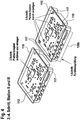
- Fig. 4 shows parts of a container 102.
- the receiving element 112 for example a circuit board
- the receiving element 112 can be guided 118 and inserted into the lower part 110 of the container 102 (step 2 according to the description of FIG Fig. 2 ).
- the board can also be fixed by pins 117 (step 3 according to the description of Fig. 2 ).
- the function of the board can be checked 120b (step 4 according to the description of FIG Fig. 2 ).
- Fig. 5 shows parts of a container 102.
- step 2 of station II is carried out as described in FIG Fig. 2 explained.
- an intermediate piece "bulkhead” can optionally be punched out of a film and it can be clipped 119c or inserted into the lower part 110 of the container 102.
- Fig. 6 shows a container 102.
- the container 102 comprises the upper part 108, for example a lid, and the lower part 110.
- step 5 of station IV is carried out according to the description of FIG Fig. 2 explained.
- the cover can be fed in and then spot welded.
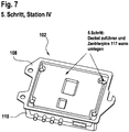
- Fig. 7 shows a container 102.
- the container 102 comprises the upper part 108, for example a lid, the lower part 110 and the receiving element 112 (not shown in FIG Fig. 7 ).
- step 5 of station IV is carried out as described in FIG Fig. 2 explained.
- the upper part 108 can hold down the receiving element 112, for example an equipped circuit board, and the upper part 108 can be connected to the lower part 110 to form the finished unit by hot forming the centering pins 117, optionally by screwing with plastic screws (not shown).
- the upper part 108 and the lower part 110 can, depending on requirements, be deep-drawn from a metal foil.
- Fig. 8 shows a schematic representation of a container 102.
- the container 102 comprises the upper part 108, the lower part 110 and the receiving element 112.
- the container 102 can be produced according to the method 100.
- This production of the container 102 requires only low costs. Furthermore, there is no delivery or logistics effort for the production of the upper part 108 and the lower part 110 of the container 102.
- the container 102 can in particular comprise electronic units and sensors with mounted electronic modules (equipped circuit boards) and can be used in particular in the automotive industry.
Landscapes
- Engineering & Computer Science (AREA)
- Mechanical Engineering (AREA)
- Microelectronics & Electronic Packaging (AREA)
- Physics & Mathematics (AREA)
- Fluid Mechanics (AREA)
- Blow-Moulding Or Thermoforming Of Plastics Or The Like (AREA)
- Lining Or Joining Of Plastics Or The Like (AREA)
- Details Of Rigid Or Semi-Rigid Containers (AREA)
- Making Paper Articles (AREA)
- Casings For Electric Apparatus (AREA)
- Containers And Plastic Fillers For Packaging (AREA)
- Containers Having Bodies Formed In One Piece (AREA)
Description
- Die vorliegende Erfindung betrifft ein Verfahren zur Herstellung eines Behälters, insbesondere eines Behälters für elektronische Module.
- Elektronische Module, beispielsweise bestückte Leiterplatten, werden üblicherweise in separat dafür hergestellte Behälter, in der Regel zweiteilig, eingelegt und gesichert. Danach werden die Behälter verschlossen.
- Üblicherweise werden zur Herstellung eines derartigen Behälters die Teile eines Behälters aus Kunststoff im Spritzgießverfahren hergestellt, während die metallischen Teile des Behälters im Sinterguß bzw. in Präge-Stanztechnik hergestellt werden. Dadurch wird der Behälter in einer Mehrzahl von unterschiedlichen Herstellungsstationen hergestellt, wodurch die Herstellungskosten des Behälters steigen.
- Aus der
US 20150373867 A1 geht ein Verfahren zum Bilden einer Motorsteuereinheit hervor, wobei ein Metallgehäuse mit einem ersten Gehäuseabschnitt, einen Biegeabschnitt, der einheitlich mit dem ersten Gehäuseabschnitt ausgebildet ist, und einen zweiten Gehäuseabschnitt, der einstückig mit dem Biegeabschnitt ausgebildet ist, gestanzt wird und der Biegeabschnitt um den ersten und den zweiten Gehäuseabschnitt miteinander in Kontakt zu bringen und einen inneren Hohlraum zwischen dem ersten und dem zweiten Gehäuseabschnitt zu definieren, gebogen wird. - Die
EP 2 860 119 A1 betrifft eine Tiefziehverpackungsmaschine mit einer ersten Formstation zum Formen einer Mulde in eine Unterfolie und einer zweiten Formstation zum Formen eines Deckels in eine Oberfolie, sowie eine Siegelstation zum Versiegeln von Mulden mit Deckeln. - Es ist daher die Aufgabe der vorliegenden Erfindung, ein effizienteres Verfahren zur Herstellung eines Behälters, insbesondere eines Behälters für elektronische Module, zur Verfügung zu stellen.
- Diese Aufgabe wird durch die Gegenstände der unabhängigen Ansprüche gelöst. Bevorzugte Ausführungsformen der Erfindung sind Gegenstand der abhängigen Ansprüche, der Beschreibung sowie der Figuren.
- Die Erfindung basiert auf der Erkenntnis, dass die obige Aufgabe durch eine direkte Herstellung eines Behälters mit der Montage der elektronischen Module in dem Behälter, unter Verwendung einer Herstellungsvorrichtung, gelöst werden kann.
- Gemäß einem ersten Aspekt wird die Aufgabe durch ein Verfahren zur Herstellung eines Behälters mit einem Oberteil, einem Unterteil und einem Aufnahmeelement gelöst. Das Verfahren weist zumindest die folgenden Schritte auf: Erstellen des Unterteils aus einem ersten Edukt in einem ersten Bearbeitungsbereich einer Bearbeitungsvorrichtung, Erstellen des Oberteils aus einem zweiten Edukt in einem zweiten Bearbeitungsbereich der Bearbeitungsvorrichtung, Führen des Aufnahmeelements in den ersten Bearbeitungsbereich der Bearbeitungsvorrichtung, Aufnehmen des Aufnahmeelements durch das Unterteil in dem ersten Bearbeitungsbereich der Bearbeitungsvorrichtung, Führen des Oberteils von dem zweiten Bearbeitungsbereich der Bearbeitungsvorrichtung in den ersten Bearbeitungsbereich der Bearbeitungsvorrichtung und Zusammenfügen von dem Oberteil und dem Unterteil zu dem Behälter in dem ersten Bearbeitungsbereich der Bearbeitungsvorrichtung. Erfindungsgemäß ist das Aufnahmeelement ein elektrisches aktives Element, wobei das Verfahren ferner den Schritt des elektrischen Kontaktierens des durch das Unterteil aufgenommenen Aufnahmeelements aufweist.
- Dadurch wird beispielsweise der technische Vorteil erreicht, dass das Oberteil und das Unterteil des Behälters in derselben Herstellungsvorrichtung hergestellt werden können.
- Dadurch wird weiterhin der technische Vorteil erreicht, dass für die Herstellung des Behälters, insbesondere für das Fertigungs- und Montagekonzept, nur geringe Kosten entstehen.
- Dadurch wird weiterhin der technische Vorteil erreicht, dass das Aufnahmeelement in derselben Herstellungsvorrichtung, in der das Oberteil und das Unterteil des Behälters hergestellt werden, verbaut und geprüft werden kann. Das Aufnahmeelement kann ein vorgefertigtes elektronisches Modul sein.
- Gemäß einer bevorzugten Ausführungsform erfolgt das Erstellen des Unterteils aus einem ersten Edukt und/oder das Erstellen des Oberteils aus einem zweiten Edukt durch Umformen des ersten Edukts und/oder des zweiten Edukts.
- Gemäß einer weiteren bevorzugten Ausführungsform umfasst das Umformen ein Tiefziehen.
- Gemäß einer weiteren bevorzugten Ausführungsform umfasst das Umformen ein Abrollen des in aufgerollter Form bereitgestellten ersten Edukts und/oder zweiten Edukts.
- Dadurch wird beispielsweise der technische Vorteil erreicht, dass verringerte Werkzeugkosten für die Teile des Behälters bei der Fertigung durch ein Tiefziehen entstehen.
- Dadurch wird weiter der technische Vorteil erreicht, dass die im Automobilbau bevorzugten Teile des Behälters durch ein Folien-Tiefziehen hergestellt werden können. Weiterhin können auch metallische Teile des Behälters mit kleiner Dicke im Metallfolien-Tiefziehen von der Rolle hergestellt werden.
- Gemäß einer vorteilhaften Ausführungsform erfolgt das Erstellen des Unterteils aus einem ersten Edukt und/oder das Erstellen des Oberteils aus einem zweiten Edukt durch Stanzen.
- Gemäß einer weiteren bevorzugten Ausführungsform ist das Aufnahmeelement eine bestückte Leiterplatte.
- Gemäß einer weiteren bevorzugten Ausführungsform umfasst das Verfahren den Schritt des elektrischen Prüfens der Funktionsfähigkeit des elektrisch kontaktierten Aufnahmeelements.
- Gemäß einer weiteren bevorzugten Ausführungsform umfasst das Verfahren den Schritt des Bereitstellens von Kunststoff als erstes Edukt und/oder als zweites Edukt.
- Gemäß einer weiteren bevorzugten Ausführungsform entspricht das erste Edukt dem zweiten Edukt.
- Gemäß einer weiteren bevorzugten Ausführungsform erfolgt das Erstellen des Oberteils in dem zweiten Bearbeitungsbereich der Bearbeitungsvorrichtung in unmittelbarer Umgebung, insbesondere angrenzend zu dem Erstellen des Unterteils in dem ersten Bearbeitungsbereich der Bearbeitungsvorrichtung.
- Gemäß einer weiteren bevorzugten Ausführungsform wird das Führen des Oberteils von dem zweiten Bearbeitungsbereich in den ersten Bearbeitungsbereich automatisiert durchgeführt.
- Gemäß einer weiteren bevorzugten Ausführungsform wird das Aufnehmen des Aufnahmeelements durch das Unterteil in dem ersten Bearbeitungsbereich der Bearbeitungsvorrichtung vor dem Zusammenfügen von dem Oberteil und dem Unterteil zu dem Behälter in dem ersten Bearbeitungsbereich der Bearbeitungsvorrichtung durchgeführt.
- Gemäß einer vorteilhaften Ausführungsform erfolgt das Aufnehmen des Aufnahmeelements durch das Unterteil durch Verschrauben und/oder durch Warmverformung eines Verbindungselements.
- Gemäß einem zweiten Aspekt wird die Aufgabe durch einen Behälter mit einem Oberteil, einem Unterteil und einem Aufnahmeelement, bereitgestellt gemäß eines Verfahrens nach mindestens einem der vorherigen bevorzugten Ausführungsformen, gelöst.
- Weitere Ausführungsbeispiele werden bezugnehmend auf die beiliegenden Figuren näher erläutert:
-
Fig. 1 zeigt eine schematische Darstellung eines Verfahrens zur Herstellung eines Behälters. -
Fig. 2 zeigt eine weitere schematische Darstellung eines Verfahrens zur Herstellung eines Behälters. -
Fig. 3 zeigt Teile eines Behälters. -
Fig. 4 zeigt Teile eines Behälters. -
Fig. 5 zeigt Teile eines Behälters. -
Fig. 6 zeigt einen Behälter. -
Fig. 7 zeigt einen Behälter. -
Fig. 8 zeigt eine schematische Darstellung eines Behälters. - In der folgenden ausführlichen Beschreibung wird auf die beiliegenden Zeichnungen Bezug genommen, die einen Teil hiervon bilden und in denen als Veranschaulichung spezifische Ausführungsformen gezeigt sind, in denen die Erfindung ausgeführt werden kann. Es versteht sich, dass auch andere Ausführungsformen genutzt und strukturelle oder logische Änderungen vorgenommen werden können, ohne von dem Konzept der vorliegenden Erfindung abzuweichen. Die folgende ausführliche Beschreibung ist deshalb nicht in einem beschränkenden Sinne zu verstehen. Ferner versteht es sich, dass die Merkmale der verschiedenen hierin beschriebenen Ausführungsbeispiele miteinander kombiniert werden können, sofern nicht spezifisch etwas anderes angegeben ist.
- Die Aspekte und Ausführungsformen werden unter Bezugnahme auf die Zeichnungen beschrieben, wobei gleiche Bezugszeichen sich im Allgemeinen auf gleiche Elemente beziehen. In der folgenden Beschreibung werden zu Erläuterungszwecken zahlreiche spezifische Details dargelegt, um ein eingehendes Verständnis von einem oder mehreren Aspekten der Erfindung zu vermitteln. Für einen Fachmann kann es jedoch offensichtlich sein, dass ein oder mehrere Aspekte oder Ausführungsformen mit einem geringeren Grad der spezifischen Details ausgeführt werden können. In anderen Fällen werden bekannte Strukturen und Elemente in schematischer Form dargestellt, um das Beschreiben von einem oder mehreren Aspekten oder Ausführungsformen zu erleichtern. Es versteht sich, dass andere Ausführungsformen genutzt und strukturelle oder logische Änderungen vorgenommen werden können, ohne von dem Konzept der vorliegenden Erfindung abzuweichen, wie in den beigefügten Ansprüchen definiert ist.
- Wenngleich ein bestimmtes Merkmal oder ein bestimmter Aspekt einer Ausführungsform bezüglich nur einer von mehreren Implementierungen offenbart worden sein mag, kann außerdem ein derartiges Merkmal oder ein derartiger Aspekt mit einem oder mehreren anderen Merkmalen oder Aspekten der anderen Implementierungen kombiniert werden, wie für eine gegebene oder bestimmte Anwendung erwünscht und vorteilhaft sein kann. Weiterhin sollen in dem Ausmaß, in dem die Ausdrücke "enthalten", "haben", "mit" oder andere Varianten davon entweder in der ausführlichen Beschreibung oder den Ansprüchen verwendet werden, solche Ausdrücke auf eine Weise ähnlich dem Ausdruck "umfassen" einschließend sein. Die Ausdrücke "gekoppelt" und "verbunden" können zusammen mit Ableitungen davon verwendet worden sein. Es versteht sich, dass derartige Ausdrücke dazu verwendet werden, um anzugeben, dass zwei Elemente unabhängig davon miteinander kooperieren oder interagieren, ob sie in direktem physischem oder elektrischem Kontakt stehen oder nicht in direktem Kontakt miteinander stehen. Außerdem ist der Ausdruck "beispielhaft" lediglich als ein Beispiel aufzufassen anstatt der Bezeichnung für das Beste oder Optimale. Die folgende Beschreibung ist deshalb nicht in einem einschränkenden Sinne zu verstehen.
Fig. 1 zeigt eine schematische Darstellung eines Verfahrens 100 zur Herstellung eines Behälters 102. In dieser Ausführungsform umfasst das Verfahren 100 zumindest die folgenden Schritte: Erstellen 114 eines Unterteiles 110 des Behälters 102 in einem ersten Bearbeitungsbereich 115a einer Bearbeitungsvorrichtung 115, Erstellen 116 eines Oberteiles 108 des Behälters 102 in einem zweiten Bearbeitungsbereich 115b der Bearbeitungsvorrichtung 115, Führen 118 eines Aufnahmeelements 112 in den ersten Bearbeitungsbereich 115a der Bearbeitungsvorrichtung 115, Aufnehmen 120 des Aufnahmeelements 112 durch das Unterteil 110 in dem ersten Bearbeitungsbereich 115a der Bearbeitungsvorrichtung 115, Führen 122 des Oberteils 108 von dem zweitem Bearbeitungsbereich 115b in den ersten Bearbeitungsbereich 115a der Bearbeitungsvorrichtung 115 und Zusammenfügen 124 von dem Oberteil 108 und dem Unterteil 110 zu dem Behälter 102 in dem ersten Bearbeitungsbereich 115a der Bearbeitungsvorrichtung 115. - Das Verfahren 100 hat beispielsweise den technischen Vorteil, dass das Oberteil 108 und das Unterteil 110 des Behälters 102 in derselben Bearbeitungsvorrichtung 115 hergestellt werden können.
-
Fig. 2 zeigt eine weitere schematische Darstellung eines Verfahrens 100 zur Herstellung eines Behälters 102. In diesem Ausführungsbeispiel umfasst das Verfahren 100 vier Stationen sowie fünf Schritte zur Herstellung des Behälters 102. - In Station I (Schritt 1) werden das Unterteil 110 und das Oberteil 108 des Behälters 102 hergestellt. Das Unterteil 110 kann aus einem ersten Edukt 200 in einem ersten Bearbeitungsbereich 115a einer Bearbeitungsvorrichtung 115 erstellt 114 werden. Das Oberteil 108 kann aus einem zweiten Edukt 202 in einem zweiten Bearbeitungsbereich 115b der Bearbeitungsvorrichtung 115 erstellt 116 werden. Das Unterteil 110 und das Oberteil 108 können durch Umformen in einem Folien-Tiefziehverfahren des entsprechenden Edukts, bzw. 200 und 202, über Vakuum (gegebenenfalls mit Hilfe von Überdruck), hergestellt werden, wobei die Edukte 200 und 202 auf einer Rolle bzw. 200a und 202a aufgerollt sind. Die Tiefziehwerkzeuge 115c und 115d können in die gesamte Bearbeitungsvorrichtung 115 integriert sein.
- In Station II, im Schritt 2, kann das Aufnahmeelement 112 in den ersten Bearbeitungsbereich 115a der Bearbeitungsvorrichtung 115 geführt 118 werden und es kann durch das Unterteil 110 in dem ersten Bearbeitungsbereich 115a aufgenommen 120 werden. Das Aufnahmeelement 112 kann ein elektrisch aktives Element, insbesondere eine komplett bestückt Leiterplatte, sein und es kann automatisch durch das Unterteil 110 aufgenommen 120 werden. Das Aufnahmeelement 112 kann beim Aufnehmen 120 über gehäuseseitige Pins 117 zentriert werden.
- In Station II, im Schritt 3, kann das Aufnahmeelement 112, beispielsweise eine Leiterplatte, niedergehalten und fixiert werden. Dies kann durch Warmverformung der gehäuseseitigen Zentrierpins 117 erfolgen, wahlweise auch durch Verschrauben mit Kunststoff-Schrauben (nicht dargestellt). Die Schritte 2 und 3 können auf derselben Station (II) der Bearbeitungsvorrichtung 115 durchgeführt werden.
- Zusätzlich kann das Verfahren 100 den Schritt des elektrischen Kontaktierens 120a des durch das Unterteil 110 aufgenommenen Aufnahmeelements 112 umfassen. Weiterhin können metallische Befestigungsteile 119a und 119b in das Oberteil 108 oder in das Unterteil 110 montiert, bevorzugt genietet, werden.
- In Station III (Schritt 4) kann die Funktionsfähigkeit des elektrisch kontaktierten Aufnahmeelements 112, beispielsweise einer bestückten Leiterplatte, geprüft 120b werden.
- In Station IV (Schritt 5) kann das Oberteil 108 von dem zweiten Bearbeitungsbereich 115b der Bearbeitungsvorrichtung 115 in den ersten Bearbeitungsbereich 115a der Bearbeitungsvorrichtung 115 geführt 122 werden. Weiterhin können das Oberteil 108 und das Unterteil 110 zu dem Behälter 102 in dem ersten Bearbeitungsbereich 115a der Bearbeitungsvorrichtung 115 zusammengefügt 124 werden. Das Oberteil 108, beispielsweise ein Deckel, kann automatisch zugeführt werden und punktuell bzw. flächig mit dem Unterteil 110 verschweißt werden. Gegebenenfalls kann das Oberteil 108, je nach Funktionsanforderung, auch verklipst werden.
- Mit der Herstellung des Oberteils 108 und des Unterteils 101 im Tiefziehverfahren von den Rollen 200a und 202a wird die verkettete Fertigung des Behälters 102 auf einer Bearbeitungsvorrichtung 115 ermöglicht.
-
Fig. 3 zeigt Teile eines Behälters 102, die im ersten Schritt der Station I gemäß der Beschreibung vonFig. 2 erstellt werden können. Im ersten Schritt der Station I können das Oberteil 108 und das Unterteil 110 des Behälters 102 durch ein Tiefziehverfahren erstellt werden. Das Unterteil 110 kann von einer Rolle 200a, die ein erstes Edukt 200 umfasst, in einem ersten Bearbeitungsbereich 115a, erstellt werden. Das Oberteil 108 kann von einer Rolle 202a, die ein zweites Edukt 202 umfasst, in einem zweiten Bearbeitungsbereich 115b, erstellt werden. Die Bearbeitungsvorrichtung 115 kann den ersten Bearbeitungsbereich 115a und den zweiten Bearbeitungsbereich 115b umfassen. InFig. 3 wird ein optionaler Schritt der Station I gezeigt, der das Ausstanzen 121 des Oberteils 108 und des Unterteils 110 des Behälters 102 umfasst. -
Fig. 4 zeigt Teile eines Behälters 102. InFig. 4 werden Teile des Behälters 102 gezeigt, die in Station II und Station III gemäß der Beschreibung vonFig. 2 erstellt werden können. In diesem Ausführungsbeispiel kann das Aufnahmeelement 112, beispielsweise eine Platine, in das Unterteil 110 des Behälters 102 geführt 118 und eingelegt werden (Schritt 2 gemäß der Beschreibung vonFig. 2 ). Die Platine kann auch durch Pins 117 fixiert werden (Schritt 3 gemäß der Beschreibung vonFig. 2 ) . Weiterhin kann die Funktion der Platine geprüft 120b werden (Schritt 4 gemäß der Beschreibung vonFig. 2 ). -
Fig. 5 zeigt Teile eines Behälters 102. In diesem Ausführungsbeispiel wird der Schritt 2 der Station II gemäß der Beschreibung vonFig. 2 erläutert. Für entsprechende Steckerausführungen auf dem Aufnahmeelement 112, beispielsweise auf einer bestückten Leiterplatte, kann gegebenenfalls ein Zwischenstück "Schott" aus einer Folie gestanzt werden und es kann in dem Unterteil 110 des Behälters 102 geklipst 119c oder eingesetzt werden. -
Fig. 6 zeigt einen Behälter 102. Der Behälter 102 umfasst das Oberteil 108, beispielsweise einen Deckel, und das Unterteil 110. In diesem Ausführungsbeispiel wird der Schritt 5 der Station IV gemäß der Beschreibung vonFig. 2 erläutert. Der Deckel kann zugeführt werden und dann punktuell verschweißt werden. -
Fig. 7 zeigt einen Behälter 102. Der Behälter 102 umfasst das Oberteil 108, beispielsweise einen Deckel, das Unterteil 110 und das Aufnahmeelement 112 (nicht gezeigt inFig. 7 ). In diesem Ausführungsbeispiel wird der Schritt 5 der Station IV gemäß der Beschreibung vonFig. 2 erläutert. In diesem Ausführungsbeispiel kann das Oberteil 108 das Aufnahmeelement 112, beispielsweise eine bestückte Platine, niederhalten und kann das Oberteil 108 durch Warmumformen der Zentrierpins 117, wahlweise durch Verschrauben mit Kunststoffschrauben (nicht dargestellt), mit dem Unterteil 110 zur fertigen Einheit verbunden werden. Das Oberteil 108 und das Unterteil 110 können, je nach Anforderung, aus einer Metallfolie tiefgezogen werden. -
Fig. 8 zeigt eine schematische Darstellung eines Behälters 102. Der Behälter 102 umfasst das Oberteil 108, das Unterteil 110 und das Aufnahmeelement 112. Der Behälter 102 kann gemäß des Verfahrens 100 hergestellt werden. - Diese Herstellung des Behälters 102, insbesondere das Fertigungs- und Montagekonzept, erfordert nur geringe Kosten. Weiterhin entsteht kein Zuliefer- und Logistik-Aufwand für die Herstellung des Oberteils 108 und des Unterteils 110 des Behälters 102.
- Der Behälter 102 kann insbesondere elektronische Einheiten und Sensoren mit montierten elektronischen Modulen (bestückte Leiterplatten) umfassen und kann insbesondere in der Automobilindustrie verwendet werden.
-
- 100
- Verfahren
- 102
- Behälter
- 108
- Oberteil
- 110
- Unterteil
- 112
- Aufnahmeelement
- 114
- Erstellen
- 115
- Bearbeitungsvorrichtung
- 115a
- Bearbeitungsbereich
- 115b
- Bearbeitungsbereich
- 115c
- Tiefziehwerkzeug
- 115d
- Tiefziehwerkzeug
- 116
- Erstellen
- 117
- Pin
- 118
- Führen
- 119a
- Befestigungsteil
- 119b
- Befestigungsteil
- 119c
- Klipsen
- 120
- Aufnehmen
- 120a
- Kontaktieren
- 120b
- Prüfen
- 121
- Ausstanzen
- 122
- Führen
- 124
- Zusammenfügen
- 200
- Edukt
- 200a
- Rolle
- 202
- Edukt
- 202a
- Rolle
Claims (13)
- Verfahren (100) zur Herstellung eines Behälters (102) mit einem Oberteil (108), einem Unterteil (110) und einem Aufnahmeelement (112), zumindest aufweisend die folgenden Schritte:Erstellen (114) des Unterteils (110) aus einem ersten Edukt (200) in einem ersten Bearbeitungsbereich (115a) einer Bearbeitungsvorrichtung (115);Erstellen (116) des Oberteils (108) aus einem zweiten Edukt (202) in einem zweiten Bearbeitungsbereich (115b) der Bearbeitungsvorrichtung (115);Führen (118) des Aufnahmeelements (112) in den ersten Bearbeitungsbereich (115a) der Bearbeitungsvorrichtung (115);Aufnehmen (120) des Aufnahmeelements (112) durch das Unterteil (110) in dem ersten Bearbeitungsbereich (115a) der Bearbeitungsvorrichtung (115);Führen (122) des Oberteils (108) von dem zweiten Bearbeitungsbereich (115b) der Bearbeitungsvorrichtung (115) in den ersten Bearbeitungsbereich (115a) der Bearbeitungsvorrichtung (115); undZusammenfügen (124) von dem Oberteil (108) und dem Unterteil (110) zu dem Behälter (102) in dem ersten Bearbeitungsbereich (115a) der Bearbeitungsvorrichtung (115),dadurch gekennzeichnet, dassdas Aufnahmeelement (112) ein elektrisches aktives Element ist, wobei das Verfahren ferner den Schritt des elektrischen Kontaktierens (120a) des durch das Unterteil (110) aufgenommenen Aufnahmeelements (112) aufweist.
- Verfahren (100) nach Anspruch 1, wobei das Erstellen (114) des Unterteils (110) aus einem ersten Edukt (200) und/oder das Erstellen (116) des Oberteils (108) aus einem zweiten Edukt (202) durch Umformen des ersten Edukts (200) und/oder des zweiten Edukts (202) erfolgt.
- Verfahren (100) nach Anspruch 2, wobei das Umformen ein Tiefziehen umfasst.
- Verfahren (100) nach Anspruch 3, wobei das Umformen ein Abrollen des in aufgerollter Form bereitgestellten ersten Edukts (200) und/oder zweiten Edukts (202) umfasst.
- Verfahren (100) nach Anspruch 1, wobei das Erstellen (114) des Unterteils (110) aus einem ersten Edukt (200) und/oder das Erstellen (116) des Oberteils (108) aus einem zweiten Edukt (202) durch Stanzen erfolgt.
- Verfahren (100) nach mindestens einem der vorherigen Ansprüche, wobei das Aufnahmeelement (112) eine bestückte Leiterplatte.
- Verfahren (100) nach zumindest einem der vorhergehenden Ansprüche, ferner aufweisend den Schritt des elektrischen Prüfens (120b) der Funktionsfähigkeit des elektrisch kontaktierten Aufnahmeelements (112).
- Verfahren (100) nach mindestens einem der vorherigen Ansprüche, ferner aufweisend den Schritt des Bereitstellens von Kunststoff als erstes Edukt (200) und/oder als zweites Edukt (202) .
- Verfahren (100) nach mindestens einem der vorherigen Ansprüche, wobei das erste Edukt (200) dem zweiten Edukt (202) entspricht.
- Verfahren (100) nach mindestens einem der vorherigen Ansprüche, wobei das Erstellen (116) des Oberteils (108) in dem zweiten Bearbeitungsbereich (115b) der Bearbeitungsvorrichtung (115) in unmittelbarer Umgebung, insbesondere angrenzend, zu dem Erstellen (114) des Unterteils (110) in dem ersten Bearbeitungsbereich (115a) der Bearbeitungsvorrichtung (115) erfolgt.
- Verfahren (100) nach mindestens einem der vorherigen Ansprüche, wobei das Führen (118) des Oberteils (108) von dem zweiten Bearbeitungsbereich (115b) in den ersten Bearbeitungsbereich (115a) automatisiert durchgeführt wird.
- Verfahren (100) nach mindestens einem der vorherigen Ansprüche, wobei das Aufnehmen (120) des Aufnahmeelements (112) durch das Unterteil (110) in dem ersten Bearbeitungsbereich (115a) der Bearbeitungsvorrichtung (115) vor dem Zusammenfügen (124) von dem Oberteil (108) und dem Unterteil (110) zu dem Behälter (102) in dem ersten Bearbeitungsbereich (115a) der Bearbeitungsvorrichtung (115) durchgeführt wird.
- Verfahren (100) nach mindestens einem der vorherigen Ansprüche, wobei das Aufnehmen (120) des Aufnahmeelements (112) durch das Unterteil (110) durch Verschrauben und/oder durch Warmverformung eines Verbindungselements erfolgt.
Applications Claiming Priority (2)
| Application Number | Priority Date | Filing Date | Title |
|---|---|---|---|
| DE102016211018.7A DE102016211018A1 (de) | 2016-06-21 | 2016-06-21 | Verfahren zur Herstellung eines Behälters |
| PCT/DE2017/200042 WO2017220090A1 (de) | 2016-06-21 | 2017-05-11 | Verfahren zur herstellung eines behälters |
Publications (2)
| Publication Number | Publication Date |
|---|---|
| EP3471904A1 EP3471904A1 (de) | 2019-04-24 |
| EP3471904B1 true EP3471904B1 (de) | 2020-10-07 |
Family
ID=59067434
Family Applications (1)
| Application Number | Title | Priority Date | Filing Date |
|---|---|---|---|
| EP17730367.4A Active EP3471904B1 (de) | 2016-06-21 | 2017-05-11 | Verfahren zur herstellung eines behälters |
Country Status (9)
| Country | Link |
|---|---|
| US (1) | US11318524B2 (de) |
| EP (1) | EP3471904B1 (de) |
| JP (1) | JP6886478B2 (de) |
| CN (1) | CN109414749B (de) |
| DE (2) | DE102016211018A1 (de) |
| ES (1) | ES2832701T3 (de) |
| HU (1) | HUE052132T2 (de) |
| MX (1) | MX2018015362A (de) |
| WO (1) | WO2017220090A1 (de) |
Families Citing this family (1)
| Publication number | Priority date | Publication date | Assignee | Title |
|---|---|---|---|---|
| DE102019216250A1 (de) * | 2019-10-22 | 2021-04-22 | Brose Fahrzeugteile Se & Co. Kommanditgesellschaft, Bamberg | Elektronik eines Kraftfahrzeugs |
Citations (1)
| Publication number | Priority date | Publication date | Assignee | Title |
|---|---|---|---|---|
| EP2860119A1 (de) * | 2013-10-09 | 2015-04-15 | Multivac Sepp Haggenmüller GmbH & Co. KG | Tiefziehverpackungsmaschine und Verfahren |
Family Cites Families (23)
| Publication number | Priority date | Publication date | Assignee | Title |
|---|---|---|---|---|
| DE1924421B2 (de) * | 1969-05-13 | 1971-09-09 | Gehaeuse fuer elektronische geraete mit steckbaren leiter platten | |
| JPS5379688A (en) * | 1976-12-23 | 1978-07-14 | Tadao Watanabe | Continuous sealing method and apparatus for same |
| JPS584367Y2 (ja) * | 1978-03-01 | 1983-01-25 | 三菱電機株式会社 | 結合構造 |
| JPS54130271U (de) * | 1978-03-02 | 1979-09-10 | ||
| GB2145363B (en) * | 1983-08-23 | 1986-09-24 | Grace W R & Co | Vacuum skin package |
| JPS62267126A (ja) | 1986-05-14 | 1987-11-19 | Toppan Printing Co Ltd | プラスチックケ−スの組立て方法及び装置 |
| CA2008537A1 (en) * | 1989-05-12 | 1990-11-12 | Marvin R. Havens | Permanently antistatic polymeric rigid containers |
| JPH03150071A (ja) * | 1990-10-04 | 1991-06-26 | Tamura Seisakusho Co Ltd | 電源装置の製造方法 |
| US5270641A (en) | 1992-01-22 | 1993-12-14 | Everett Charles Technologies, Inc. | Dual side access test fixture |
| EP0727932B1 (de) * | 1994-11-28 | 1999-04-07 | Kabushiki Kaisha Toshiba | Gehäuse mit elektromagnetischer Abschirmung |
| DE19961675A1 (de) | 1999-12-21 | 2001-06-28 | Philips Corp Intellectual Pty | Bauteil mit Dünnschichtschaltkreis mit trimmbarem Kondensator |
| DE20215425U1 (de) * | 2002-10-08 | 2004-02-19 | Knobel Ag Lichttechnische Komponenten | Gehäuse für eine Leiterplatte |
| FR2846476B1 (fr) * | 2002-10-28 | 2005-01-28 | Legrand Sa | Plaque support pour appareillage electrique |
| JP4299152B2 (ja) * | 2004-01-08 | 2009-07-22 | 日本碍子株式会社 | 電磁波シールドケースおよびその製造方法 |
| DE102005039673B4 (de) * | 2005-04-19 | 2013-12-19 | Gerhard Schubert Gmbh | Verfahren und Vorrichtung zum Herstellen von befüllten und dicht versiegelten Kunststoff-Tiefziehbehältern |
| JP5071447B2 (ja) | 2009-07-14 | 2012-11-14 | 株式会社デンソー | 電子制御装置 |
| JP4969661B2 (ja) * | 2010-01-20 | 2012-07-04 | 三菱電機株式会社 | 電子制御ユニット及びその製造方法 |
| DE102012006787A1 (de) * | 2012-04-04 | 2013-10-10 | Inter Control Hermann Köhler Elektrik GmbH & Co. KG | Erweiterbares Gehäuse für elektrische Bauteile, Zwischengehäuseteil für das erweiterbare Gehäuse, sowie Verfahren zur Herstellung und zur Montage des Gehäuses |
| JP6321342B2 (ja) * | 2013-08-29 | 2018-05-09 | 大森機械工業株式会社 | 深絞り包装機 |
| CN203600783U (zh) | 2013-11-28 | 2014-05-21 | 珠海天威飞马打印耗材有限公司 | 耗材芯片及耗材容器 |
| DE102014208425A1 (de) | 2013-11-28 | 2015-05-28 | Continental Teves Ag & Co. Ohg | Verfahren zum Herstellen eines Sensors |
| US20150373867A1 (en) * | 2014-06-18 | 2015-12-24 | Continental Automotive Systems, Inc. | Electronics housing |
| CN105391008A (zh) | 2015-10-13 | 2016-03-09 | 天津市建电实业有限公司 | 一种一体化成型的户箱体及其生产方法 |
-
2016
- 2016-06-21 DE DE102016211018.7A patent/DE102016211018A1/de not_active Withdrawn
-
2017
- 2017-05-11 US US16/099,062 patent/US11318524B2/en active Active
- 2017-05-11 MX MX2018015362A patent/MX2018015362A/es unknown
- 2017-05-11 HU HUE17730367A patent/HUE052132T2/hu unknown
- 2017-05-11 CN CN201780036657.5A patent/CN109414749B/zh active Active
- 2017-05-11 ES ES17730367T patent/ES2832701T3/es active Active
- 2017-05-11 WO PCT/DE2017/200042 patent/WO2017220090A1/de not_active Ceased
- 2017-05-11 JP JP2018547332A patent/JP6886478B2/ja active Active
- 2017-05-11 DE DE112017000479.9T patent/DE112017000479A5/de not_active Withdrawn
- 2017-05-11 EP EP17730367.4A patent/EP3471904B1/de active Active
Patent Citations (1)
| Publication number | Priority date | Publication date | Assignee | Title |
|---|---|---|---|---|
| EP2860119A1 (de) * | 2013-10-09 | 2015-04-15 | Multivac Sepp Haggenmüller GmbH & Co. KG | Tiefziehverpackungsmaschine und Verfahren |
Also Published As
| Publication number | Publication date |
|---|---|
| JP6886478B2 (ja) | 2021-06-16 |
| US11318524B2 (en) | 2022-05-03 |
| CN109414749A (zh) | 2019-03-01 |
| ES2832701T3 (es) | 2021-06-11 |
| MX2018015362A (es) | 2019-08-05 |
| JP2019521852A (ja) | 2019-08-08 |
| US20190143393A1 (en) | 2019-05-16 |
| HUE052132T2 (hu) | 2021-04-28 |
| EP3471904A1 (de) | 2019-04-24 |
| WO2017220090A1 (de) | 2017-12-28 |
| DE112017000479A5 (de) | 2018-09-27 |
| DE102016211018A1 (de) | 2017-12-21 |
| CN109414749B (zh) | 2021-06-04 |
Similar Documents
| Publication | Publication Date | Title |
|---|---|---|
| DE102015210603B4 (de) | Verfahren zur Herstellung einer Halbleitervorrichtung | |
| EP3770989B1 (de) | Batteriegehäuse für eine fahrzeugbatterie | |
| DE102004011702B4 (de) | Verfahren zur Herstellung eines Kartenkörpers für eine kontaktlose Chipkarte | |
| DE102015220473B4 (de) | Verfahren zum Herstellen eines Gehäusebauteils mit Schirmung vor elektromagnetischer Strahlung und mit Umweltdichtungsfunktion | |
| DE112008000488T5 (de) | Metallplatine mit Bindemitteltrimmkomponente sowie Verfahren | |
| WO1998001315A1 (de) | Kraftstoffbehälter und verfahren zu seiner herstellung | |
| DE19754645A1 (de) | Dichtungseinsatz und Verfahren zu seiner Herstellung | |
| DE112012000659T5 (de) | Elektrodraht-Anschluss-Verbindungsaufbau und Verfahren zum Herstellen desselben | |
| EP1870970B1 (de) | Verfahren zur Herstellung eines elektrischen Hybridbauteils | |
| DE102011086791A1 (de) | Verfahren zum Verschließen einer Bohrung eines Werkstückes und Bohrungsverschlussvorrichtung | |
| EP3471904B1 (de) | Verfahren zur herstellung eines behälters | |
| DE112015005405T5 (de) | Anschlussbestückter Batteriegehäusedeckel und versiegelte Batterie | |
| EP1914022B1 (de) | Verfahren und Werkzeug zum Herstellen von durch Umform- und Feinschneidvorgänge erzeugte dreidimensionale Beschläge | |
| WO2005016624A1 (de) | Hybridbauteil und zugehöriges herstellungsverfahren | |
| EP1743404A1 (de) | Verfahren zur herstellung eines kunststoffumspritzten stanzgitters und kunststoffumspritztes stanzgitter | |
| EP4039385A1 (de) | Verfahren und formvorrichtung zur umformung einer metallverbundfolie für batteriezellen | |
| EP3906124B1 (de) | Verfahren zur herstellung einer kühlplatte | |
| DE102015119669B4 (de) | Anschlussbauteil und Verfahren zum Herstellen eines Anschlussbauteils für eine Batterie | |
| DE102024136366A1 (de) | Airbaghalter mit montageverhinderung und -überprüfung | |
| WO2013117446A1 (de) | GEHÄUSE FÜR EINE BATTERIEZELLE MIT EINER THERMOGEFORMTEN AUßENSCHALE AUS KUNSTSTOFF, BATTERIEZELLE, BATTERIEMODUL SOWIE KRAFTFAHRZEUG | |
| DE102017113448A1 (de) | Werkzeuganordnung und Verfahren zum Herstellen einer Karosserieplatte | |
| EP3437843A1 (de) | Verfahren zur herstellung eines verkleidungsteils | |
| DE102017222950A1 (de) | Gehäuse für einen Gassack eines Fahrzeuginsassen-Rückhaltesystems eines Kraftfahrzeugs, formgebende Vorrichtung und Verfahren zum Herstellen eines derartigen Gehäuses | |
| DE102023132428A1 (de) | Verfahren zum Herstellen eines Batteriemoduls mit verbesserter Crashsicherheit, Batteriemodul für ein Kraftfahrzeug und Montagevorrichtung | |
| DE102004018997B4 (de) | Elektronisches Gerät sowie Verfahren zur Herstellung eines derartigen elektronischen Geräts |
Legal Events
| Date | Code | Title | Description |
|---|---|---|---|
| STAA | Information on the status of an ep patent application or granted ep patent |
Free format text: STATUS: UNKNOWN |
|
| STAA | Information on the status of an ep patent application or granted ep patent |
Free format text: STATUS: THE INTERNATIONAL PUBLICATION HAS BEEN MADE |
|
| PUAI | Public reference made under article 153(3) epc to a published international application that has entered the european phase |
Free format text: ORIGINAL CODE: 0009012 |
|
| STAA | Information on the status of an ep patent application or granted ep patent |
Free format text: STATUS: REQUEST FOR EXAMINATION WAS MADE |
|
| 17P | Request for examination filed |
Effective date: 20190121 |
|
| AK | Designated contracting states |
Kind code of ref document: A1 Designated state(s): AL AT BE BG CH CY CZ DE DK EE ES FI FR GB GR HR HU IE IS IT LI LT LU LV MC MK MT NL NO PL PT RO RS SE SI SK SM TR |
|
| AX | Request for extension of the european patent |
Extension state: BA ME |
|
| DAV | Request for validation of the european patent (deleted) | ||
| DAX | Request for extension of the european patent (deleted) | ||
| STAA | Information on the status of an ep patent application or granted ep patent |
Free format text: STATUS: EXAMINATION IS IN PROGRESS |
|
| 17Q | First examination report despatched |
Effective date: 20191017 |
|
| REG | Reference to a national code |
Ref country code: DE Ref legal event code: R079 Ref document number: 502017007621 Country of ref document: DE Free format text: PREVIOUS MAIN CLASS: B21D0051520000 Ipc: B65B0041160000 |
|
| GRAP | Despatch of communication of intention to grant a patent |
Free format text: ORIGINAL CODE: EPIDOSNIGR1 |
|
| STAA | Information on the status of an ep patent application or granted ep patent |
Free format text: STATUS: GRANT OF PATENT IS INTENDED |
|
| RIC1 | Information provided on ipc code assigned before grant |
Ipc: B65B 47/06 20060101ALI20200529BHEP Ipc: B65B 41/16 20060101AFI20200529BHEP |
|
| INTG | Intention to grant announced |
Effective date: 20200707 |
|
| GRAS | Grant fee paid |
Free format text: ORIGINAL CODE: EPIDOSNIGR3 |
|
| GRAA | (expected) grant |
Free format text: ORIGINAL CODE: 0009210 |
|
| STAA | Information on the status of an ep patent application or granted ep patent |
Free format text: STATUS: THE PATENT HAS BEEN GRANTED |
|
| AK | Designated contracting states |
Kind code of ref document: B1 Designated state(s): AL AT BE BG CH CY CZ DE DK EE ES FI FR GB GR HR HU IE IS IT LI LT LU LV MC MK MT NL NO PL PT RO RS SE SI SK SM TR |
|
| REG | Reference to a national code |
Ref country code: GB Ref legal event code: FG4D Free format text: NOT ENGLISH |
|
| REG | Reference to a national code |
Ref country code: CH Ref legal event code: EP Ref country code: AT Ref legal event code: REF Ref document number: 1320952 Country of ref document: AT Kind code of ref document: T Effective date: 20201015 |
|
| REG | Reference to a national code |
Ref country code: IE Ref legal event code: FG4D Free format text: LANGUAGE OF EP DOCUMENT: GERMAN |
|
| REG | Reference to a national code |
Ref country code: DE Ref legal event code: R096 Ref document number: 502017007621 Country of ref document: DE |
|
| REG | Reference to a national code |
Ref country code: RO Ref legal event code: EPE |
|
| REG | Reference to a national code |
Ref country code: NL Ref legal event code: MP Effective date: 20201007 |
|
| REG | Reference to a national code |
Ref country code: HU Ref legal event code: AG4A Ref document number: E052132 Country of ref document: HU |
|
| PG25 | Lapsed in a contracting state [announced via postgrant information from national office to epo] |
Ref country code: FI Free format text: LAPSE BECAUSE OF FAILURE TO SUBMIT A TRANSLATION OF THE DESCRIPTION OR TO PAY THE FEE WITHIN THE PRESCRIBED TIME-LIMIT Effective date: 20201007 Ref country code: GR Free format text: LAPSE BECAUSE OF FAILURE TO SUBMIT A TRANSLATION OF THE DESCRIPTION OR TO PAY THE FEE WITHIN THE PRESCRIBED TIME-LIMIT Effective date: 20210108 Ref country code: RS Free format text: LAPSE BECAUSE OF FAILURE TO SUBMIT A TRANSLATION OF THE DESCRIPTION OR TO PAY THE FEE WITHIN THE PRESCRIBED TIME-LIMIT Effective date: 20201007 Ref country code: PT Free format text: LAPSE BECAUSE OF FAILURE TO SUBMIT A TRANSLATION OF THE DESCRIPTION OR TO PAY THE FEE WITHIN THE PRESCRIBED TIME-LIMIT Effective date: 20210208 Ref country code: NO Free format text: LAPSE BECAUSE OF FAILURE TO SUBMIT A TRANSLATION OF THE DESCRIPTION OR TO PAY THE FEE WITHIN THE PRESCRIBED TIME-LIMIT Effective date: 20210107 |
|
| REG | Reference to a national code |
Ref country code: LT Ref legal event code: MG4D |
|
| PG25 | Lapsed in a contracting state [announced via postgrant information from national office to epo] |
Ref country code: SE Free format text: LAPSE BECAUSE OF FAILURE TO SUBMIT A TRANSLATION OF THE DESCRIPTION OR TO PAY THE FEE WITHIN THE PRESCRIBED TIME-LIMIT Effective date: 20201007 Ref country code: LV Free format text: LAPSE BECAUSE OF FAILURE TO SUBMIT A TRANSLATION OF THE DESCRIPTION OR TO PAY THE FEE WITHIN THE PRESCRIBED TIME-LIMIT Effective date: 20201007 Ref country code: IS Free format text: LAPSE BECAUSE OF FAILURE TO SUBMIT A TRANSLATION OF THE DESCRIPTION OR TO PAY THE FEE WITHIN THE PRESCRIBED TIME-LIMIT Effective date: 20210207 Ref country code: PL Free format text: LAPSE BECAUSE OF FAILURE TO SUBMIT A TRANSLATION OF THE DESCRIPTION OR TO PAY THE FEE WITHIN THE PRESCRIBED TIME-LIMIT Effective date: 20201007 Ref country code: BG Free format text: LAPSE BECAUSE OF FAILURE TO SUBMIT A TRANSLATION OF THE DESCRIPTION OR TO PAY THE FEE WITHIN THE PRESCRIBED TIME-LIMIT Effective date: 20210107 |
|
| REG | Reference to a national code |
Ref country code: ES Ref legal event code: FG2A Ref document number: 2832701 Country of ref document: ES Kind code of ref document: T3 Effective date: 20210611 |
|
| PG25 | Lapsed in a contracting state [announced via postgrant information from national office to epo] |
Ref country code: NL Free format text: LAPSE BECAUSE OF FAILURE TO SUBMIT A TRANSLATION OF THE DESCRIPTION OR TO PAY THE FEE WITHIN THE PRESCRIBED TIME-LIMIT Effective date: 20201007 Ref country code: HR Free format text: LAPSE BECAUSE OF FAILURE TO SUBMIT A TRANSLATION OF THE DESCRIPTION OR TO PAY THE FEE WITHIN THE PRESCRIBED TIME-LIMIT Effective date: 20201007 |
|
| REG | Reference to a national code |
Ref country code: DE Ref legal event code: R097 Ref document number: 502017007621 Country of ref document: DE |
|
| PG25 | Lapsed in a contracting state [announced via postgrant information from national office to epo] |
Ref country code: EE Free format text: LAPSE BECAUSE OF FAILURE TO SUBMIT A TRANSLATION OF THE DESCRIPTION OR TO PAY THE FEE WITHIN THE PRESCRIBED TIME-LIMIT Effective date: 20201007 Ref country code: LT Free format text: LAPSE BECAUSE OF FAILURE TO SUBMIT A TRANSLATION OF THE DESCRIPTION OR TO PAY THE FEE WITHIN THE PRESCRIBED TIME-LIMIT Effective date: 20201007 Ref country code: SM Free format text: LAPSE BECAUSE OF FAILURE TO SUBMIT A TRANSLATION OF THE DESCRIPTION OR TO PAY THE FEE WITHIN THE PRESCRIBED TIME-LIMIT Effective date: 20201007 Ref country code: SK Free format text: LAPSE BECAUSE OF FAILURE TO SUBMIT A TRANSLATION OF THE DESCRIPTION OR TO PAY THE FEE WITHIN THE PRESCRIBED TIME-LIMIT Effective date: 20201007 |
|
| PLBE | No opposition filed within time limit |
Free format text: ORIGINAL CODE: 0009261 |
|
| STAA | Information on the status of an ep patent application or granted ep patent |
Free format text: STATUS: NO OPPOSITION FILED WITHIN TIME LIMIT |
|
| PG25 | Lapsed in a contracting state [announced via postgrant information from national office to epo] |
Ref country code: DK Free format text: LAPSE BECAUSE OF FAILURE TO SUBMIT A TRANSLATION OF THE DESCRIPTION OR TO PAY THE FEE WITHIN THE PRESCRIBED TIME-LIMIT Effective date: 20201007 |
|
| 26N | No opposition filed |
Effective date: 20210708 |
|
| PG25 | Lapsed in a contracting state [announced via postgrant information from national office to epo] |
Ref country code: IT Free format text: LAPSE BECAUSE OF FAILURE TO SUBMIT A TRANSLATION OF THE DESCRIPTION OR TO PAY THE FEE WITHIN THE PRESCRIBED TIME-LIMIT Effective date: 20201007 Ref country code: AL Free format text: LAPSE BECAUSE OF FAILURE TO SUBMIT A TRANSLATION OF THE DESCRIPTION OR TO PAY THE FEE WITHIN THE PRESCRIBED TIME-LIMIT Effective date: 20201007 |
|
| PG25 | Lapsed in a contracting state [announced via postgrant information from national office to epo] |
Ref country code: SI Free format text: LAPSE BECAUSE OF FAILURE TO SUBMIT A TRANSLATION OF THE DESCRIPTION OR TO PAY THE FEE WITHIN THE PRESCRIBED TIME-LIMIT Effective date: 20201007 |
|
| REG | Reference to a national code |
Ref country code: CH Ref legal event code: PL |
|
| GBPC | Gb: european patent ceased through non-payment of renewal fee |
Effective date: 20210511 |
|
| PG25 | Lapsed in a contracting state [announced via postgrant information from national office to epo] |
Ref country code: LU Free format text: LAPSE BECAUSE OF NON-PAYMENT OF DUE FEES Effective date: 20210511 Ref country code: MC Free format text: LAPSE BECAUSE OF FAILURE TO SUBMIT A TRANSLATION OF THE DESCRIPTION OR TO PAY THE FEE WITHIN THE PRESCRIBED TIME-LIMIT Effective date: 20201007 Ref country code: LI Free format text: LAPSE BECAUSE OF NON-PAYMENT OF DUE FEES Effective date: 20210531 Ref country code: CH Free format text: LAPSE BECAUSE OF NON-PAYMENT OF DUE FEES Effective date: 20210531 |
|
| REG | Reference to a national code |
Ref country code: BE Ref legal event code: MM Effective date: 20210531 |
|
| PG25 | Lapsed in a contracting state [announced via postgrant information from national office to epo] |
Ref country code: IE Free format text: LAPSE BECAUSE OF NON-PAYMENT OF DUE FEES Effective date: 20210511 Ref country code: GB Free format text: LAPSE BECAUSE OF NON-PAYMENT OF DUE FEES Effective date: 20210511 |
|
| PG25 | Lapsed in a contracting state [announced via postgrant information from national office to epo] |
Ref country code: IS Free format text: LAPSE BECAUSE OF FAILURE TO SUBMIT A TRANSLATION OF THE DESCRIPTION OR TO PAY THE FEE WITHIN THE PRESCRIBED TIME-LIMIT Effective date: 20210207 |
|
| PG25 | Lapsed in a contracting state [announced via postgrant information from national office to epo] |
Ref country code: BE Free format text: LAPSE BECAUSE OF NON-PAYMENT OF DUE FEES Effective date: 20210531 |
|
| REG | Reference to a national code |
Ref country code: DE Ref legal event code: R081 Ref document number: 502017007621 Country of ref document: DE Owner name: CONTINENTAL AUTOMOTIVE TECHNOLOGIES GMBH, DE Free format text: FORMER OWNER: CONTINENTAL TEVES AG & CO. OHG, 60488 FRANKFURT, DE Ref country code: DE Ref legal event code: R081 Ref document number: 502017007621 Country of ref document: DE Owner name: AUMOVIO GERMANY GMBH, DE Free format text: FORMER OWNER: CONTINENTAL TEVES AG & CO. OHG, 60488 FRANKFURT, DE |
|
| REG | Reference to a national code |
Ref country code: HU Ref legal event code: GB9C Owner name: CONTINENTAL AUTOMOTIVE TECHNOLOGIES GMBH, DE Free format text: FORMER OWNER(S): CONTINENTAL TEVES AG & CO. OHG, DE |
|
| P01 | Opt-out of the competence of the unified patent court (upc) registered |
Effective date: 20230522 |
|
| PG25 | Lapsed in a contracting state [announced via postgrant information from national office to epo] |
Ref country code: CY Free format text: LAPSE BECAUSE OF FAILURE TO SUBMIT A TRANSLATION OF THE DESCRIPTION OR TO PAY THE FEE WITHIN THE PRESCRIBED TIME-LIMIT Effective date: 20201007 |
|
| REG | Reference to a national code |
Ref country code: AT Ref legal event code: MM01 Ref document number: 1320952 Country of ref document: AT Kind code of ref document: T Effective date: 20220511 |
|
| PG25 | Lapsed in a contracting state [announced via postgrant information from national office to epo] |
Ref country code: AT Free format text: LAPSE BECAUSE OF NON-PAYMENT OF DUE FEES Effective date: 20220511 |
|
| REG | Reference to a national code |
Ref country code: DE Ref legal event code: R081 Ref document number: 502017007621 Country of ref document: DE Owner name: CONTINENTAL AUTOMOTIVE TECHNOLOGIES GMBH, DE Free format text: FORMER OWNER: CONTINENTAL AUTOMOTIVE TECHNOLOGIES GMBH, 30165 HANNOVER, DE Ref country code: DE Ref legal event code: R081 Ref document number: 502017007621 Country of ref document: DE Owner name: AUMOVIO GERMANY GMBH, DE Free format text: FORMER OWNER: CONTINENTAL AUTOMOTIVE TECHNOLOGIES GMBH, 30165 HANNOVER, DE |
|
| PG25 | Lapsed in a contracting state [announced via postgrant information from national office to epo] |
Ref country code: MK Free format text: LAPSE BECAUSE OF FAILURE TO SUBMIT A TRANSLATION OF THE DESCRIPTION OR TO PAY THE FEE WITHIN THE PRESCRIBED TIME-LIMIT Effective date: 20201007 |
|
| REG | Reference to a national code |
Ref country code: ES Ref legal event code: PC2A Owner name: CONTINENTAL AUTOMOTIVE TECHNOLOGIES GMBH Effective date: 20240529 |
|
| PG25 | Lapsed in a contracting state [announced via postgrant information from national office to epo] |
Ref country code: MT Free format text: LAPSE BECAUSE OF FAILURE TO SUBMIT A TRANSLATION OF THE DESCRIPTION OR TO PAY THE FEE WITHIN THE PRESCRIBED TIME-LIMIT Effective date: 20201007 |
|
| PGFP | Annual fee paid to national office [announced via postgrant information from national office to epo] |
Ref country code: DE Payment date: 20250531 Year of fee payment: 9 |
|
| PGFP | Annual fee paid to national office [announced via postgrant information from national office to epo] |
Ref country code: HU Payment date: 20250523 Year of fee payment: 9 |
|
| PGFP | Annual fee paid to national office [announced via postgrant information from national office to epo] |
Ref country code: FR Payment date: 20250528 Year of fee payment: 9 |
|
| PGFP | Annual fee paid to national office [announced via postgrant information from national office to epo] |
Ref country code: RO Payment date: 20250505 Year of fee payment: 9 |
|
| PGFP | Annual fee paid to national office [announced via postgrant information from national office to epo] |
Ref country code: CZ Payment date: 20250505 Year of fee payment: 9 |
|
| PGFP | Annual fee paid to national office [announced via postgrant information from national office to epo] |
Ref country code: ES Payment date: 20250630 Year of fee payment: 9 |
|
| PG25 | Lapsed in a contracting state [announced via postgrant information from national office to epo] |
Ref country code: TR Free format text: LAPSE BECAUSE OF FAILURE TO SUBMIT A TRANSLATION OF THE DESCRIPTION OR TO PAY THE FEE WITHIN THE PRESCRIBED TIME-LIMIT Effective date: 20201007 |
|
| REG | Reference to a national code |
Ref country code: DE Ref legal event code: R081 Ref document number: 502017007621 Country of ref document: DE Owner name: AUMOVIO GERMANY GMBH, DE Free format text: FORMER OWNER: CONTINENTAL AUTOMOTIVE TECHNOLOGIES GMBH, 30175 HANNOVER, DE |