EP3472019B1 - Fahrzeug mit einem türportal und einem portaldichtrahmen - Google Patents
Fahrzeug mit einem türportal und einem portaldichtrahmen Download PDFInfo
- Publication number
- EP3472019B1 EP3472019B1 EP17735501.3A EP17735501A EP3472019B1 EP 3472019 B1 EP3472019 B1 EP 3472019B1 EP 17735501 A EP17735501 A EP 17735501A EP 3472019 B1 EP3472019 B1 EP 3472019B1
- Authority
- EP
- European Patent Office
- Prior art keywords
- portal
- door
- side parts
- sealing frame
- vehicle
- Prior art date
- Legal status (The legal status is an assumption and is not a legal conclusion. Google has not performed a legal analysis and makes no representation as to the accuracy of the status listed.)
- Active
Links
Images



Classifications
-
- B—PERFORMING OPERATIONS; TRANSPORTING
- B61—RAILWAYS
- B61D—BODY DETAILS OR KINDS OF RAILWAY VEHICLES
- B61D19/00—Door arrangements specially adapted for rail vehicles
- B61D19/001—Door arrangements specially adapted for rail vehicles for wagons or vans
-
- B—PERFORMING OPERATIONS; TRANSPORTING
- B60—VEHICLES IN GENERAL
- B60J—WINDOWS, WINDSCREENS, NON-FIXED ROOFS, DOORS, OR SIMILAR DEVICES FOR VEHICLES; REMOVABLE EXTERNAL PROTECTIVE COVERINGS SPECIALLY ADAPTED FOR VEHICLES
- B60J10/00—Sealing arrangements
-
- B—PERFORMING OPERATIONS; TRANSPORTING
- B60—VEHICLES IN GENERAL
- B60J—WINDOWS, WINDSCREENS, NON-FIXED ROOFS, DOORS, OR SIMILAR DEVICES FOR VEHICLES; REMOVABLE EXTERNAL PROTECTIVE COVERINGS SPECIALLY ADAPTED FOR VEHICLES
- B60J5/00—Doors
-
- B—PERFORMING OPERATIONS; TRANSPORTING
- B61—RAILWAYS
- B61D—BODY DETAILS OR KINDS OF RAILWAY VEHICLES
- B61D19/00—Door arrangements specially adapted for rail vehicles
-
- B—PERFORMING OPERATIONS; TRANSPORTING
- B61—RAILWAYS
- B61D—BODY DETAILS OR KINDS OF RAILWAY VEHICLES
- B61D19/00—Door arrangements specially adapted for rail vehicles
- B61D19/02—Door arrangements specially adapted for rail vehicles for carriages
Definitions
- the invention relates to a vehicle which comprises a door portal and a portal sealing frame which is connected to the door portal and which has a plurality of side parts connected to one another.
- portal sealing frame also called “portal frame” for short
- the portal sealing frame represents a sealing surface on which a seal can be applied, which is used to seal the entrance door against the door portal.
- the pamphlet CN 2487585 Y relates to a door that has a frame made of aluminum profiles with recesses. Sealing strips for sealing the door against the door frame are glued into the recesses.
- the utility model DE 20 2007 008 782 U1 teaches a passenger door for a public transport vehicle. This has a sealing element which runs vertically along a closing edge of the passenger door and which, in the closed position of the door, rests against a sealing strip arranged on the door portal.
- One object of the invention is to achieve improved tightness on the door portal of a vehicle of the type mentioned at the beginning.
- the vehicle according to the invention comprises a door portal and a portal sealing frame which is connected to the door portal and has a plurality of side parts connected to one another. Furthermore, in the vehicle according to the invention, at least one of the side parts of the portal sealing frame is connected to the door portal by means of an adhesive connection, and each of the side parts has several recesses to reduce its rigidity.
- the invention is based on the consideration that the door portal can have production-related tolerances, i.e. deviations from its desired shape.
- the door portal can have (local) unevenness.
- the invention is also based on the idea that previously the portal sealing frame has been fastened to the door portal with the aid of screws. When the screws are tightened, angular errors can be transferred from the screw-on surfaces of the door portal to the portal sealing frame. This can lead to leaks at the door portal.
- a side part of the portal sealing frame can be understood to mean a (partial) section of the portal sealing frame.
- the vehicle can in particular be a vehicle used in passenger traffic.
- the vehicle is preferably a rail vehicle.
- the vehicle can be a bus, for example.
- the door portal is expediently part of a car body of the vehicle.
- the car body of the vehicle can have one or more door portals.
- the vehicle can have its own portal sealing frame for each door portal of the car body.
- the description below refers to the aforementioned door portal and to the aforementioned portal sealing frame. Any further door portals and portal sealing frames of the vehicle can be designed in the same way as this door portal and this portal sealing frame.
- the said side part of the portal sealing frame which is connected to the door portal by means of an adhesive connection, is advantageously connected to the door portal exclusively by means of the adhesive connection.
- this side part is advantageously not attached to the door portal by means of any other type of connection, such as a screw connection.
- each of the side parts of the portal sealing frame is connected to the door portal by means of an adhesive connection, in particular exclusively by means of an adhesive connection.
- the portal sealing frame preferably has two longitudinal side parts. It is also advantageous if the portal sealing frame has at least one narrow side part.
- the narrow side part is expediently connected to the longitudinal side parts. In particular, the narrow side part can be connected directly to the two longitudinal side parts.
- both longitudinal side parts are at least essentially the same length.
- the length of the long side parts expediently defines the height of the portal sealing frame.
- the length of the narrow side part in turn expediently defines the width of the portal sealing frame.
- the long side parts are expediently designed to be longer than the narrow side part.
- the narrow side part is connected at one of its two ends to one of the two long side parts. At the other of its two ends, the narrow side part is expediently connected to the other of the two longitudinal side parts.
- the portal sealing frame can comprise a further narrow side part.
- each of the two narrow side parts can be connected at one of its two ends to one of the two long side parts and at the other of its two ends to the other of the two long side parts.
- the further narrow side part is preferably at least essentially the same length as the first-mentioned narrow side part.
- the two long side parts and the narrow side part (s) are usefully the initially mentioned side parts of the portal sealing frame.
- the long side parts and the narrow side part (s) can be designed as separate components of the portal sealing frame.
- the longitudinal side parts can, for example, be non-positively connected to the narrow side part (s), in particular by means of screw, adhesive and / or rivet connections.
- the narrow side part (s) is / are formed in one piece with the longitudinal side parts.
- the entire portal sealing frame can be manufactured in one piece, for example with the aid of a 3D printing process.
- the side parts of the portal sealing frame preferably consist at least predominantly of metal, in particular of aluminum.
- the side parts consist exclusively of metal.
- metal is not necessarily to be understood as a single metal, but can also include a metal alloy.
- all the side parts of the portal sealing frame are made of the same material or the same combination of materials. In this way it can be achieved that the side parts have the same material properties, in particular the same flexural and / or torsional rigidity.
- the side parts of the portal sealing frame are each designed as a profile component, in particular as an extruded profile, or as a sheet metal part.
- Such components are inexpensive and inexpensive to produce and thus enable the portal sealing frame to be produced inexpensively and with low effort.
- a preferred development of the invention provides that the side parts of the portal sealing frame each have a fastening strip. It is also advantageous if the side parts of the portal sealing frame each have a sealing strip which is expediently connected to the fastening strip of the same side part.
- the fastening strip of the respective side part can be designed in one piece with its sealing strip.
- Each of the side parts of the portal sealing frame is expediently connected to the door portal at its fastening strip.
- the sealing strip of the respective side part is arranged perpendicularly or essentially perpendicularly to its fastening strip.
- the side parts of the portal sealing frame preferably each have an L-shaped or a T-shaped cross-sectional shape. Furthermore, it is expedient if the side parts of the portal sealing frame have a wall thickness of at most 5 mm, in particular at most 3 mm.
- the portal sealing frame has a low rigidity, in particular a low flexural and / or torsional rigidity.
- At least one of the side parts has several recesses to reduce its rigidity.
- the functional feature "to reduce its rigidity” can be understood to mean that the side part has recesses that reduce its rigidity, in particular its flexural and / or torsional rigidity - compared to a side part that has no such recesses but is otherwise identical is.
- An assembly jig is usually used to attach the portal sealing frame to the door portal. With the help of the assembly jig, the evenness and contour accuracy of the gantry sealing frame can be checked and its correct installation position in relation to the door gantry can be determined.
- a low rigidity of the respective side part of the portal sealing frame enables the side part to be adapted to the shape of the assembly jig at low cost - in particular without laborious manual messaging, so that any leaks caused by contour deviations between the side part of the gantry sealing frame and the assembly jig are avoided.
- each of the side parts has a plurality of cutouts to reduce its rigidity.
- the entire portal sealing frame can be adapted to the shape of the assembly template at low cost.
- the recesses of the respective side part are preferably designed as slots. It is also preferred if the recesses of the respective side part are provided in its fastening strip.
- the recesses can in particular be arranged in this way in the respective fastening strip be that the respective fastening strip forms a comb-like structure.
- the recesses of the respective side part can be arranged next to one another in its longitudinal direction. Furthermore, the recesses of the respective side part can be arranged equidistant from one another or at different distances from one another.
- the vehicle is expediently equipped with an access door.
- the entrance door in turn expediently has at least one door leaf. It is also advantageous if the entry door has at least one sealing element with a sealing lip which is fastened to the door leaf.
- the sealing element expediently serves to seal the entry door against the door portal or the portal sealing frame attached to the door portal.
- the sealing element preferably consists at least predominantly of an elastomer, such as rubber.
- the sealing lip advantageously rests at least in sections on the portal sealing frame, in particular on the sealing surface of one of the side parts of the portal sealing frame.
- the sealing lip is preferably spaced apart from the portal sealing frame, that is to say is arranged without contact with the portal sealing frame.
- the access door is designed as a pivoting sliding door.
- the invention also relates to a method for fastening a portal sealing frame to a door portal of a vehicle, in which the portal sealing frame has a plurality of side parts connected to one another.
- At least one of the side parts of the portal sealing frame by means of an adhesive connection is connected to the door portal, each of the side parts having several recesses to reduce its rigidity.
- said side part of the portal sealing frame can be connected to the door portal at low cost.
- each of the side parts of the portal sealing frame is connected to the door portal by means of an adhesive connection, in particular exclusively by means of an adhesive connection. This means that all side parts of the portal sealing frame can be attached to the door portal at low cost.
- the portal sealing frame is expediently fixed to an assembly jig before it is connected to the door portal, for example with the aid of quick-release clamping elements.
- the assembly jig is then expediently inserted into the door portal together with the portal sealing frame.
- FIG 1 shows a rail vehicle 2 in a schematic representation.
- an entry door 4 of the rail vehicle 2 and its car body 6 are shown by way of example.
- the rail vehicle 2 can in addition to the illustrated entrance door 4 have one or more additional entrance doors, which are not shown figuratively for the sake of clarity.
- the entry door 4 of the rail vehicle 2 comprises a door leaf 8 and is designed as a pivoting sliding door.
- the entrance door 4 is shown in the closed state and its longitudinal direction 10 is shown in the form of an arrow.
- FIG 1 a sectional plane II-II is shown, which runs perpendicular to the longitudinal direction 10 of the access door 4 through a section of the door leaf 8 and through a section of the car body 6.
- FIG 2 shows a section through a section of the door leaf 8 and through a section of the car body 6 along the section plane II-II from FIG 1 .
- FIG 2 it can be seen that the car body 6 has a door portal 12.
- a portal sealing frame 14 of the rail vehicle 2 more precisely a longitudinal side part 16 of the portal sealing frame 14, is shown.
- the portal sealing frame 14 comprises two such longitudinal side parts 16 as well as two narrow side parts 18 connected to the longitudinal side parts 16, which are each designed as separate components which are connected to one another (cf. FIG 3 ). Both the longitudinal side parts 16 and the narrow side parts 18 are designed as profile components.
- the side parts 16, 18 of the portal sealing frame 14 are each made of aluminum.
- Each of the side parts 16, 18 of the portal sealing frame 14 is connected to the door portal 12 exclusively by means of an adhesive connection. Screw connections which connect the portal sealing frame 14 to the door portal 12 are not provided.
- each of the side parts 16, 18 of the portal sealing frame 14 comprises a fastening strip 20 and a sealing strip 22, which is formed in one piece with the fastening strip 20 and aligned perpendicular to the fastening strip 20, the side parts 16, 18 of the portal sealing frame 14 on their respective fastening strip 20 on the door portal 14 are glued.
- the side parts 16, 18 of the portal sealing frame 14 each have a T-shaped cross-sectional shape.
- the side parts 16, 18 of the portal sealing frame 14 could, for example, have an L-shaped cross-sectional shape.
- both the fastening strip 20 and the sealing strip 22 of the respective side part 16, 18 have a wall thickness d of approximately 3 mm.
- the fastening strips 20 can have a different wall thickness than the sealing strip 24.
- the access door 4 is shown in the closed state. In this state, its outside 24 is arranged flush with an outside 26 of the car body 6.
- FIG 2 a sealing element 28 of the entrance door 4 is shown, which is fastened to its door leaf 8 and serves to seal the entrance door 4 or its door leaf 8 with respect to the portal sealing frame 14.
- the sealing element 28 consists of rubber and has a sealing lip 30. In the closed state of the entrance door 4, the sealing lip 30 of the illustrated sealing element 28 rests in a sealing manner on the sealing strip 22 of the illustrated longitudinal side part 16 of the portal sealing frame 14.
- the entry door 4 has several further sealing elements (not shown in the figures) which are fastened to its door leaf 8.
- the further sealing elements In the closed state of the entrance door 4, the further sealing elements each lie in a sealing manner on one of the other side parts 16, 18, in particular on their sealing strip 22.
- an adhesive 32 by means of which the respective side part 16, 18 of the portal sealing frame 14 is glued to the door portal 12, is sealed to the outside 26 of the car body 6 by means of a sealing compound 34 and is sealed to the opposite side by means of a sealing cord 36.
- FIG 3 shows the portal sealing frame 14 in a front view.
- the two previously mentioned longitudinal side parts 16 and the two narrow side parts 18 of the portal sealing frame 14 are visible.
- Both longitudinal side parts 16 are of the same length.
- both narrow side parts 18 are designed to be of the same length, with the longitudinal side parts 16 being longer than the narrow side parts 18.
- the length L 1 of the longitudinal side parts 16 defines the height h of the portal sealing frame 14, while the length L 2 of the narrow side parts 18 defines the width b of the portal sealing frame 14.
- the portal sealing frame 14 has a rectangular basic shape, its longitudinal side parts 16 not necessarily being flat with respect to the plane of the drawing FIG 2 must be, but can have a curvature which is adapted to a possible curvature of the car body 6 in the area of the entrance door 4.
- Each of the two longitudinal side parts 16 is at one of its two ends with one of the two narrow side parts 18 and with the other of its two ends is connected to the other of the two narrow side parts 18.
- the longitudinal side parts 16 can be connected to the narrow side parts 18 with the aid of screw, adhesive and / or rivet connections.
- each of the side parts 16, 18 of the portal sealing frame 14 has a plurality of cutouts 38 for reducing its rigidity, which are designed as slots.
- the recesses 38 are shown in FIG FIG 2 (in comparison to the length L 1 of the longitudinal side parts 16 or the length L 2 of the narrow side parts 18) shown enlarged.
- the recesses 38 of the narrow side part 18 are arranged next to one another in the longitudinal direction 40 thereof.
- the recesses 38 of the longitudinal side part 16 are arranged next to one another in the longitudinal direction 42 thereof.
- the recesses 38 of the respective side part 16, 18 are provided in its fastening strip 20, the recesses 38 being arranged in the respective fastening strip 20 such that the respective fastening strip 20 forms a comb-like structure.
- the section plane II-II FIG 1 runs between two adjacent recesses 38 of that longitudinal side part 16, which in FIG 3 is shown on the right.
- the portal sealing frame 14 In order to be able to fasten the portal sealing frame 14 in its intended target position on the door portal 12, the portal sealing frame 14 is fixed to an assembly jig (not shown in the figure), for example with the aid of quick-release elements.
- the assembly jig is then inserted into the door portal 12 together with the portal sealing frame 14.
- Said cutouts 38 ensure that the port sealing frame 14 has a low flexural and torsional rigidity, so that the portal sealing frame 14 (without large Force) to the shape of the assembly jig and fits neatly against the assembly jig.
- an adhesive 32 is applied to the fastening strips 20 of the side parts 16, 18 and / or to the door portal 20. With the aid of the adhesive 32, the side parts 16, 18 of the portal sealing frame 14 are connected to the door portal 12. Furthermore, the adhesive 32 is sealed from one side by means of a sealing compound 34 and sealed from the opposite side by means of a sealing cord 36.
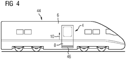
- FIG 4 shows a further rail vehicle 44 in a schematic representation.
- an entry door 4 of the rail vehicle 44 and its car body 6 are shown by way of example.
- the rail vehicle 44 has a sliding step 46 below the entry door 4 (shown).
- the sliding step 46 serves to bridge a distance between the rail vehicle 44 and a platform edge when passengers get on and off. In FIG 4 the sliding step 46 is shown in the retracted state.
- FIG 5 shows a portal sealing frame 14 of the rail vehicle 44 FIG 4 in a frontal view.
- this portal sealing frame 14 has a U-shaped basic shape, its longitudinal side parts 16 not necessarily being flat with respect to the plane of the drawing FIG 5 must be, but can have a curvature which is adapted to a possible curvature of the car body 6 in the area of the entrance door 4.
- the portal sealing frame 14 has FIG 5 only a single narrow side part 18. That is, the portal sealing frame 14 from FIG 5 the lower narrow side part 18 is absent. Otherwise, the two portal sealing frames 14 are of identical design.
- the entry door 4 of the rail vehicle 44 is sealed by means of a step rail (not shown in the figure) mounted separately on the car body 6.
- the side parts 16, 18 of the portal sealing frame 14 are connected to the door portal 12 of the rail vehicle 44 exclusively by means of an adhesive connection.
Landscapes
- Engineering & Computer Science (AREA)
- Mechanical Engineering (AREA)
- Seal Device For Vehicle (AREA)
- Specific Sealing Or Ventilating Devices For Doors And Windows (AREA)
- Body Structure For Vehicles (AREA)
Description
- Die Erfindung betrifft ein Fahrzeug, welches ein Türportal sowie einen mit dem Türportal verbundenen Portaldichtrahmen umfasst, der mehrere miteinander verbundene Seitenteile aufweist.
- Es ist bekannt, bei einem Fahrzeug, welches ein Türportal aufweist, einen Portaldichtrahmen (auch kurz "Portalrahmen" genannt) am Türportal zu befestigen, um die Dichtigkeit einer Einstiegstür des Fahrzeugs gegenüber dem Türportal gewährleisten zu können. Der Portaldichtrahmen stellt eine Dichtfläche dar, an der eine Dichtung anliegen kann, welche zum Abdichten der Einstiegstür gegenüber dem Türportal eingesetzt wird.
- Die Druckschrift
CN 2487585 Y betrifft eine Tür, die einen Rahmen aus Aluminiumprofilen mit Ausnehmungen aufweist. In die Ausnehmungen sind Dichtungsstreifen zur Abdichtung der Tür gegen den Türrahmen eingeklebt. - Die Gebrauchsmusterschrift
DE 20 2007 008 782 U1 lehrt eine Fahrgasttür für ein Fahrzeug des öffentlichen Personenverkehrs. Diese weist ein Dichtelement auf, welches vertikal entlang einer Schließkante der Fahrgasttür verläuft und welches in der geschlossenen Stellung der Tür an einer am Türportal angeordnete Abdichtleiste anliegt. - Eine Aufgabe der Erfindung ist es, bei einem Fahrzeug der eingangs genannten Art eine verbesserte Dichtigkeit an dessen Türportal zu erreichen.
- Diese Aufgabe wird erfindungsgemäß gelöst durch ein Fahrzeug mit den Merkmalen des Anspruchs 1.
- Das erfindungsgemäße Fahrzeug umfasst ein Türportal sowie einen mit dem Türportal verbundenen Portaldichtrahmen, der mehrere miteinander verbundene Seitenteile aufweist. Ferner ist bei dem erfindungsgemäßen Fahrzeug mindestens eins der Seitenteile des Portaldichtrahmens mittels einer Klebeverbindung mit dem Türportal verbunden, und jedes der Seitenteile weist mehrere Aussparungen zur Verringerung seiner Steifigkeit auf.
- Die Erfindung geht von der Überlegung aus, dass das Türportal produktionsbedingte Toleranzen, d.h. Abweichungen von seiner Soll-Form, aufweisen kann. Beispielsweise kann das Türportal (lokale) Unebenheiten aufweisen.
- Weiter geht die Erfindung von der Überlegung aus, dass bisher der Portaldichtrahmen mithilfe von Schrauben am Türportal befestigt wird. Beim Anziehen der Schrauben können Winkelfehler von Anschraubflächen des Türportals auf den Portaldichtrahmen übertragen werden. Dies kann zu Undichtigkeiten am Türportal führen.
- Dadurch, dass bei der Erfindung mindestens eins der Seitenteile des Portaldichtrahmens mittels einer Klebeverbindung mit dem Türportal verbunden ist, kann auf Schraubverbindungen, welche dieses Seitenteil des Portaldichtrahmens mit dem Türportal verbinden, verzichtet werden. Hierdurch wiederum kann eine Übertragung von Winkelfehlern auf den Portaldichtrahmen, die beim Anziehen von Schrauben entstehen kann, sowie daraus resultierende Undichtigkeiten an diesem Seitenteil des Portaldichtrahmens vermieden werden.
- Unter einem Seitenteil des Portaldichtrahmens kann vorliegend ein (Teil-)Abschnitt des Portaldichtrahmens verstanden werden.
- Bei dem Fahrzeug kann es sich insbesondere um ein im Personenverkehr eingesetztes Fahrzeug handeln. In bevorzugter Weise ist das Fahrzeug ein Schienenfahrzeug. Alternativ kann das Fahrzeug zum Beispiel ein Omnibus sein.
- Zweckmäßigerweise ist das Türportal ein Teil eines Wagenkastens des Fahrzeugs. Der Wagenkasten des Fahrzeugs kann ein oder mehrere Türportale aufweisen. Weiterhin kann das Fahrzeug für jedes Türportal des Wagenkastens einen eigenen Portaldichtrahmen aufweisen. Nachfolgend bezieht sich die Beschreibung der Einfachheit halber auf das zuvor erwähnte Türportal sowie auf den zuvor erwähnten Portaldichtrahmen. Etwaige weitere Türportale und Portaldichtrahmen des Fahrzeugs können in gleicher Weise wie dieses Türportal und dieser Portaldichtrahmen ausgeführt sein.
- Vorteilhafterweise ist das besagte Seitenteil des Portaldichtrahmens, welches mittels einer Klebeverbindung mit dem Türportal verbunden ist, ausschließlich mittels der Klebeverbindung mit dem Türportal verbunden. Mit anderen Worten, dieses Seitenteil ist vorteilhafterweise nicht mittels einer anderen Art von Verbindung, wie zum Beispiel einer Schraubverbindung, am Türportal befestigt. Durch den Verzicht auf (komplexe) Schraubverbindungen kann der Portaldichtrahmen kostengünstig hergestellt werden.
- In einer besonders vorteilhaften Ausgestaltung der Erfindung ist jedes der Seitenteile des Portaldichtrahmens mittels einer Klebeverbindung, insbesondere ausschließlich mittels einer Klebeverbindung, mit dem Türportal verbunden. Dadurch kann an allen Seitenteilen des Portaldichtrahmens auf Schraubverbindungen zur Befestigung des Portaldichtrahmens am Türportal verzichtet werden.
- Vorzugsweise weist der Portaldichtrahmen zwei Längsseitenteile auf. Weiter ist es vorteilhaft, wenn der Portaldichtrahmen mindestens ein Schmalseitenteil aufweist. Zweckmäßigerweise ist das Schmalseitenteil mit den Längsseitenteilen verbunden. Insbesondere kann das Schmalseitenteil unmittelbar mit den beiden Längsseitenteilen verbunden sein.
- Ferner ist es vorteilhaft, wenn beide Längsseitenteile zumindest im Wesentlichen gleich lang sind. Die Länge der Längsseitenteile definiert zweckmäßigerweise die Höhe des Portaldichtrahmens. Die Länge des Schmalseitenteils wiederum definiert zweckmäßigerweise die Breite des Portaldichtrahmens. Sinnvollerweise sind die Längsseitenteile länger als das Schmalseitenteil ausgeführt.
- Des Weiteren ist es zweckmäßig, wenn das Schmalseitenteil an einem seiner beiden Enden mit einem der beiden Längsseitenteile verbunden ist. An dem anderen seiner beiden Enden ist das Schmalseitenteil zweckmäßigerweise mit dem anderen der beiden Längsseitenteile verbunden.
- Außerdem kann der Portaldichtrahmen ein weiteres Schmalseitenteil umfassen. In diesem Fall kann jedes der beiden Schmalseitenteile an einem seiner beiden Enden mit einem der beiden Längsseitenteile und mit dem anderen seiner beiden Ende mit dem anderen der beiden Längsseitenteile verbunden sein. In bevorzugter Weise ist das weitere Schmalseitenteil zumindest im Wesentlichen gleich lang wie das erstgenannte Schmalseitenteil.
- Bei den beiden Längsseitenteilen und dem/den Schmalseitenteil/-en handelt es sich sinnvollerweise um die eingangs genannten Seitenteile des Portaldichtrahmens.
- Die Längsseitenteile und das/die Schmalseitenteil/-e können als separate Bauteile des Portaldichtrahmens ausgebildet sein. In diesem Fall können die Längsseitenteile beispielsweise kraftschlüssig, insbesondere mittels Schraub-, Klebe- und/oder Nietverbindungen, mit dem/den Schmalseitenteil/-en verbunden sein. Alternativ kann vorgesehen sein, dass das/die Schmalseitenteil/-e einstückig mit den Längsseitenteilen ausgebildet ist/sind. Mit anderen Worten, der gesamte Portaldichtrahmen kann in einem Stück gefertigt sein, beispielsweise mithilfe eines 3D-Druckverfahrens.
- Vorzugsweise bestehen die Seitenteile des Portaldichtrahmens zumindest überwiegend aus Metall, insbesondere aus Aluminium.
- Besonders bevorzugt ist es, wenn die Seitenteile ausschließlich aus Metall bestehen. Vorliegend ist der Begriff "Metall" nicht notwendigerweise als ein einzelnes Metall zu verstehen, sondern kann auch eine Metalllegierung umfassen.
- Weiter ist es vorteilhaft, wenn alle Seitenteile des Portaldichtrahmens aus demselben Material bzw. derselben Materialkombination bestehen. Hierdurch kann erreicht werden, dass die Seitenteile gleiche Materialeigenschaften, insbesondere die gleiche Biege- und/oder Torsionssteifigkeit, aufweisen.
- In einer vorteilhaften Ausgestaltung der Erfindung sind die Seitenteile des Portaldichtrahmens jeweils als Profilbauteil, insbesondere als Strangpressprofil, oder als Blechkantteil ausgebildet. Solche Bauteile sind kosten- und aufwandsgünstig herstellbar und ermöglichen somit eine kosten- und aufwandsgünstige Herstellung des Portaldichtrahmens.
- Eine bevorzugte Weiterbildung der Erfindung sieht vor, dass die Seitenteile des Portaldichtrahmens jeweils eine Befestigungsleiste aufweisen. Weiter ist es vorteilhaft, wenn die Seitenteile des Portaldichtrahmens jeweils eine Dichtleiste aufweisen, welche zweckmäßigerweise mit der Befestigungsleiste desselben Seitenteils verbunden ist. Insbesondere kann die Befestigungsleiste des jeweiligen Seitenteils einstückig mit dessen Dichtleiste ausgebildet sein.
- Zweckmäßigerweise ist jedes der Seitenteile des Portaldichtrahmens an seiner Befestigungsleiste mit dem Türportal verbunden. Zudem ist es bevorzugt, wenn die Dichtleiste des jeweiligen Seitenteils senkrecht oder im Wesentlichen senkrecht zu dessen Befestigungsleiste angeordnet ist.
- Ferner weisen die Seitenteile des Portaldichtrahmens vorzugsweise jeweils eine L-förmige oder eine T-förmige Querschnittsform auf. Des Weiteren ist es zweckmäßig, wenn die Seitenteile des Portaldichtrahmens eine Wandungsdicke von höchstens 5 mm, insbesondere höchstens 3 mm, aufweisen.
- Dadurch kann erreicht werden, dass der Portaldichtrahmen eine geringe Steifigkeit, insbesondere eine geringe Biege- und/oder Torsionssteifigkeit, aufweist.
- Erfindungsgemäß weist mindestens eins der Seitenteile mehrere Aussparungen zur Verringerung seiner Steifigkeit auf. Das funktionale Merkmal "zur Verringerung seiner Steifigkeit" kann dahingehend verstanden werden, dass das Seitenteil Aussparungen aufweist, die dessen Steifigkeit, insbesondere dessen Biege- und/oder Torsionssteifigkeit, verringern - verglichen mit einem Seitenteil, welches keine solchen Aussparungen aufweist, aber ansonsten identisch ausgebildet ist.
- Üblicherweise wird eine Montagelehre eingesetzt, um den Portaldichtrahmen am Türportal zu befestigen. Mithilfe der Montagelehre lässt sich die Ebenheit und Konturtreue des Portaldichtrahmens prüfen und dessen korrekte Einbauposition bezüglich des Türportals bestimmen.
- Eine geringe Steifigkeit des jeweiligen Seitenteils des Portaldichtrahmens ermöglicht es, das Seitenteil aufwandsgünstig - insbesondere ohne aufwändiges Nachrichten von Hand - an die Form der Montagelehre anzupassen, sodass etwaige durch Konturabweichungen zwischen dem Seitenteil des Portaldichtrahmens und der Montagelehre bedingte Undichtigkeiten vermieden werden.
- Besonders bevorzugt ist es, wenn jedes der Seitenteile mehrere Aussparungen zur Verringerung seiner Steifigkeit aufweist. Dadurch kann der gesamte Portaldichtrahmen aufwandsgünstig an die Form der Montagelehre angepasst werden.
- Vorzugsweise sind die Aussparungen des jeweiligen Seitenteils als Schlitze ausgebildet. Weiter ist es bevorzugt, wenn die Aussparungen des jeweiligen Seitenteils in dessen Befestigungsleiste vorgesehen sind. Die Aussparungen können insbesondere derart in der jeweiligen Befestigungsleiste angeordnet sein, dass die jeweilige Befestigungsleiste eine kammartige Struktur ausbildet.
- Ferner können die Aussparungen des jeweiligen Seitenteils in dessen Längsrichtung nebeneinander angeordnet sein. Weiterhin können die Aussparungen des jeweiligen Seitenteils äquidistant zueinander oder mit verschiedenen Abständen zueinander angeordnet sein.
- Zweckmäßigerweise ist das Fahrzeug mit einer Einstiegstür ausgestattet. Die Einstiegstür wiederum weist zweckmäßigerweise mindestens einen Türflügel auf. Weiter ist es vorteilhaft, wenn die Einstiegstür mindestens ein an dem Türflügel befestigtes Dichtungselement mit einer Dichtlippe aufweist. Das Dichtungselement dient zweckmäßigerweise dazu, die Einstiegstür gegenüber dem Türportal bzw. dem am Türportal befestigten Portaldichtrahmen abzudichten. Vorzugsweise besteht das Dichtungselement zumindest überwiegend aus einem Elastomer, wie zum Beispiel Gummi.
- Im geschlossenen Zustand der Einstiegstür liegt die Dichtlippe vorteilhafterweise zumindest abschnittsweise am Portaldichtrahmen, insbesondere an der Dichtfläche eines der Seitenteile des Portaldichtrahmens, an. Im geöffneten Zustand der Einstiegstür ist die Dichtlippe vorzugsweise vom Portaldichtrahmen beabstandet, also kontaktlos zum Portaldichtrahmen angeordnet.
- Besonders bevorzugt ist es, wenn die Einstiegstür als Schwenkschiebetür ausgebildet ist.
- Des Weiteren betrifft die Erfindung ein Verfahren zum Befestigen eines Portaldichtrahmens an einem Türportal eines Fahrzeugs, bei dem der Portaldichtrahmen mehrere miteinander verbundene Seitenteile aufweist.
- Bei dem erfindungsgemäßen Verfahren ist vorgesehen, dass mindestens eins der Seitenteile des Portaldichtrahmens mittels einer Klebeverbindung mit dem Türportal verbunden wird, wobei jedes der Seitenteile mehrere Aussparungen zur Verringerung seiner Steifigkeit aufweist. Auf diese Weise kann besagtes Seitenteil des Portaldichtrahmens aufwandsgünstig mit dem Türportal verbunden werden. Insbesondere kann auf ein aufwändiges Anziehen von Schrauben und auf ein etwaiges Nachrichten des Seitenteils verzichtet werden.
- Eine vorteilhafte Weiterbildung des Verfahrens sieht vor, dass jedes der Seitenteile des Portaldichtrahmens mittels einer Klebeverbindung, insbesondere ausschließlich mittels einer Klebeverbindung, mit dem Türportal verbunden wird. Dadurch können alle Seitenteile des Portaldichtrahmens aufwandsgünstig am Türportal befestigt werden.
- Zweckmäßigerweise wird der Portaldichtrahmen, bevor er mit dem Türportal verbunden wird, an einer Montagelehre fixiert, beispielsweise mithilfe von Schnellspannelementen. Anschließend wird die Montagelehre zweckmäßigerweise zusammen mit dem Portaldichtrahmen in das Türportal eingesetzt.
- Die bisher gegebene Beschreibung vorteilhafter Ausgestaltungen der Erfindung enthält zahlreiche Merkmale, die in den einzelnen abhängigen Ansprüchen teilweise zu mehreren zusammengefasst wiedergegeben sind. Diese Merkmale können jedoch zweckmäßigerweise auch einzeln betrachtet und zu sinnvollen weiteren Kombinationen im Rahmen der Ansprüche zusammengefasst werden. Insbesondere sind diese Merkmale jeweils einzeln und in beliebiger geeigneter Kombination mit dem erfindungsgemäßen Fahrzeug und dem erfindungsgemäßen Verfahren im Rahmen der Ansprüche kombinierbar. So sind Verfahrensmerkmale auch als Eigenschaft der entsprechenden Vorrichtungseinheit zu sehen und umgekehrt.
- Auch wenn in der Beschreibung bzw. in den Patentansprüchen einige Begriffe jeweils im Singular oder in Verbindung mit einem Zahlwort verwendet werden, soll der Umfang der Erfindung für diese Begriffe nicht auf den Singular oder das jeweilige Zahlwort eingeschränkt sein.
- Die oben beschriebenen Eigenschaften, Merkmale und Vorteile der Erfindung sowie die Art und Weise, wie diese erreicht werden, werden klarer und deutlicher verständlich im Zusammenhang mit der folgenden Beschreibung der Ausführungsbeispiele der Erfindung, die im Zusammenhang mit den Zeichnungen näher erläutert werden. Die Ausführungsbeispiele dienen der Erläuterung der Erfindung und beschränken die Erfindung nicht auf die darin angegebenen Kombinationen von Merkmalen, auch nicht in Bezug auf funktionale Merkmale. Außerdem können dazu geeignete Merkmale eines jeden Ausführungsbeispiels auch explizit isoliert betrachtet, aus einem Ausführungsbeispiel entfernt, in ein anderes Ausführungsbeispiel zu dessen Ergänzung eingebracht und mit einem beliebigen der Ansprüche kombiniert werden.
- Es zeigen:
- FIG 1
- ein Schienenfahrzeug, welches eine Einstiegstür mit einem Türflügel umfasst;
- FIG 2
- einen Schnitt durch den Türflügel der Einstiegstür sowie durch ein Türportal und einen Portaldichtrahmen des Schienenfahrzeugs aus
FIG 1 ; - FIG 3
- den Portaldichtrahmen des Schienenfahrzeugs aus
FIG 1 in einer Frontalansicht; - FIG 4
- ein weiteres Schienenfahrzeug, welches eine Einstiegstür mit einem Türflügel sowie einen Schiebetritt umfasst; und
- FIG 5
- einen Portaldichtrahmen des Schienenfahrzeugs aus
FIG 4 . -
FIG 1 zeigt ein Schienenfahrzeug 2 in einer schematischen Darstellung. In dieser Figur ist exemplarisch eine Einstiegstür 4 des Schienenfahrzeugs 2 sowie dessen Wagenkasten 6 abgebildet. Das Schienenfahrzeug 2 kann zusätzlich zu der abgebildeten Einstiegstür 4 eine oder mehrere weitere Einstiegstüren aufweisen, welche einer besseren Übersichtlichkeit halber figürlich nicht dargestellt sind. - Die nachfolgende Beschreibung bezieht sich der Einfachheit halber auf die abgebildete Einstiegstür 4, wobei die nachfolgenden Ausführungen ebenso für die anderen, figürlich nicht dargestellten Einstiegstüren des Schienenfahrzeugs 2 gelten können.
- Die Einstiegstür 4 des Schienenfahrzeugs 2 umfasst einen Türflügel 8 und ist als Schwenkschiebetür ausgebildet. In
FIG 1 ist die Einstiegstür 4 im geschlossenen Zustand abgebildet und deren Längsrichtung 10 in Form eines Pfeils dargestellt. - Weiter ist in
FIG 1 eine Schnittebene II-II dargestellt, welche senkrecht zur Längsrichtung 10 der Einstiegstür 4 durch einen Abschnitt des Türflügels 8 sowie durch einen Abschnitt des Wagenkastens 6 verläuft. -
FIG 2 zeigt einen Schnitt durch einen Abschnitt des Türflügels 8 sowie durch einen Abschnitt des Wagenkastens 6 entlang der Schnittebene II-II ausFIG 1 . - Aus
FIG 2 ist ersichtlich, dass der Wagenkasten 6 ein Türportal 12 aufweist. Weiter ist inFIG 2 ein Portaldichtrahmen 14 des Schienenfahrzeugs 2, genauer gesagt ein Längsseitenteil 16 des Portaldichtrahmens 14, abgebildet. - Der Portaldichtrahmen 14 umfasst zwei solche Längsseitenteile 16 sowie zwei mit den Längsseitenteilen 16 verbundene Schmalseitenteile 18, die jeweils als separate Bauteile ausgeführt sind, welche miteinander verbunden sind (vgl.
FIG 3 ). Sowohl die Längsseitenteile 16 als auch die Schmalseitenteile 18 sind als Profilbauteile ausgebildet. Im vorliegenden Ausführungsbeispiel bestehen die Seitenteile 16, 18 des Portaldichtrahmens 14 jeweils aus Aluminium. - Jedes der Seitenteile 16, 18 des Portaldichtrahmens 14 ist ausschließlich mittels einer Klebeverbindung mit dem Türportal 12 verbunden. Schraubverbindungen, welche den Portaldichtrahmen 14 mit dem Türportal 12 verbinden, sind nicht vorgesehen.
- Des Weiteren umfasst jedes der Seitenteile 16, 18 des Portaldichtrahmens 14 eine Befestigungsleiste 20 sowie eine einstückig mit der Befestigungsleiste 20 ausgebildete, senkrecht zur Befestigungsleiste 20 ausgerichtete Dichtleiste 22, wobei die Seitenteile 16, 18 des Portaldichtrahmens 14 an ihrer jeweiligen Befestigungsleiste 20 an das Türportal 14 geklebt sind. Ferner weisen die Seitenteile 16, 18 des Portaldichtrahmens 14 jeweils eine T-förmige Querschnittsform auf. Alternativ könnten die Seitenteile 16, 18 des Portaldichtrahmens 14 beispielsweise eine L-förmige Querschnittsform aufweisen.
- Im vorliegenden Ausführungsbeispiel weist sowohl die Befestigungsleiste 20 als auch die Dichtleiste 22 des jeweiligen Seitenteils 16, 18 eine Wandungsdicke d von etwa 3 mm auf. Grundsätzlich können die Befestigungsleisten 20 eine andere Wandungsdicke als die Dichtleiste 24 aufweisen.
- Wie zuvor erwähnt, ist die Einstiegstür 4 im geschlossenen Zustand dargestellt. In diesem Zustand ist ihre Außenseite 24 bündig zu einer Außenseite 26 des Wagenkastens 6 angeordnet.
- Weiterhin ist in
FIG 2 ein Dichtungselement 28 der Einstiegstür 4 dargestellt, welches an deren Türflügel 8 befestigt ist und dazu dient, die Einstiegstür 4 bzw. ihren Türflügel 8 gegenüber dem Portaldichtrahmen 14 abzudichten. Das Dichtungselement 28 besteht aus Gummi und weist eine Dichtlippe 30 auf. Im geschlossenen Zustand der Einstiegstür 4 liegt die Dichtlippe 30 des abgebildeten Dichtungselements 28 dichtend an der Dichtleiste 22 des abgebildeten Längsseitenteils 16 des Portaldichtrahmens 14 an. - Zusätzlich zu dem abgebildeten Dichtungselement 28 weist die Einstiegstür 4 mehrere weitere (figürlich nicht dargestellte) Dichtungselemente auf, die an ihrem Türflügel 8 befestigt sind. Die weiteren Dichtungselemente liegen im geschlossen Zustand der Einstiegstür 4 jeweils dichtend an einem der anderen Seitenteile 16, 18, insbesondere an deren Dichtleiste 22, an.
- Des Weiteren ist ein Klebstoff 32, mittels welchem das jeweilige Seitenteil 16, 18 des Portaldichtrahmens 14 an das Türportal 12 geklebt ist, zur Außenseite 26 des Wagenkastens 6 hin mittels einer Versiegelungsmasse 34 versiegelt und zur gegenüberliegenden Seite hin mittels einer Dichtschnur 36 abgedichtet.
-
FIG 3 zeigt den Portaldichtrahmen 14 in einer Frontalansicht. In dieser Darstellung sind die beiden zuvor erwähnten Längsseitenteile 16 sowie die beiden Schmalseitenteile 18 des Portaldichtrahmens 14 sichtbar. - Beide Längsseitenteile 16 sind gleich lang ausgeführt. Ebenso sind beide Schmalseitenteile 18 gleich lang ausgeführt, wobei die Längsseitenteile 16 länger sind als die Schmalseitenteile 18.
- Die Länge L1 der Längsseitenteile 16 definiert die Höhe h des Portaldichtrahmens 14, während die Länge L2 der Schmalseitenteile 18 die Breite b des Portaldichtrahmens 14 definiert.
- In der dargestellten Frontalansicht hat der Portaldichtrahmen 14 eine rechteckige Grundform, wobei dessen Längsseitenteile 16 nicht notwendigerweise eben bezüglich der Zeichenebene der
FIG 2 sein müssen, sondern eine Krümmung aufweisen können, die an eine etwaige Krümmung des Wagenkastens 6 im Bereich der Einstiegstür 4 angepasst ist. - Jedes der beiden Längsseitenteile 16 ist an einem seiner beiden Enden mit einem der beiden Schmalseitenteile 18 und mit dem anderen seiner beiden Enden mit dem anderen der beiden Schmalseitenteile 18 verbunden. Beispielsweise können die Längsseitenteile 16 mithilfe von Schraub-, Klebe- und/oder Nietverbindungen mit den Schmalseitenteilen 18 verbunden sein.
- Des Weiteren weist jedes der Seitenteile 16, 18 des Portaldichtrahmens 14 mehrere Aussparungen 38 zur Verringerung seiner Steifigkeit auf, die als Schlitze ausgebildet sind. Zwecks einer besseren Darstellbarkeit sind die Aussparungen 38 in
FIG 2 (im Vergleich zur Länge L1 der Längsseitenteile 16 bzw. der Länge L2 der Schmalseitenteile 18) vergrößert abgebildet. - Die Aussparungen 38 des Schmalseitenteils 18 sind in dessen Längsrichtung 40 nebeneinander angeordnet. In analoger Weise sind die Aussparungen 38 des Längsseitenteils 16 in dessen Längsrichtung 42 nebeneinander angeordnet. Ferner sind die Aussparungen 38 des jeweiligen Seitenteils 16, 18 in dessen Befestigungsleiste 20 vorgesehen, wobei die Aussparungen 38 derart in der jeweiligen Befestigungsleiste 20 angeordnet sind, dass die jeweilige Befestigungsleiste 20 eine kammartige Struktur ausbildet.
- Die Schnittebene II-II aus
FIG 1 verläuft zwischen zwei benachbarten Aussparungen 38 desjenigen Längsseitenteils 16, welches inFIG 3 rechts abgebildet ist. - Um den Portaldichtrahmens 14 in seiner vorgesehenen SollPosition am Türportal 12 befestigen zu können, wird der Portaldichtrahmen 14 an einer (figürlich nicht dargestellten) Montagelehre fixiert, beispielweise mithilfe von Schnellspannelementen. Anschließend wird die Montagelehre zusammen mit dem Portaldichtrahmen 14 in das Türportal 12 eingesetzt. Durch besagte Aussparungen 38 wird erreicht, dass der Portdichtrahmen 14 eine geringe Biege- und Torsionssteifigkeit aufweist, sodass sich der Portaldichtrahmen 14 (ohne großen Kraftaufwand) der Form der Montagelehre anpasst und sauber an der Montagelehre anliegt.
- Bevor die Montagelehre mit dem Portaldichtrahmen 14 in das Türportal 12 eingesetzt wird, wird ein Klebstoff 32 auf die Befestigungsleisten 20 der Seitenteile 16, 18 und/oder auf das Türportal 20 aufgebracht. Mithilfe des Klebstoffs 32 werden die Seitenteile 16, 18 des Portaldichtrahmens 14 mit dem Türportal 12 verbunden. Im Weiteren wird der Klebstoff 32 von einer Seite mittels einer Versiegelungsmasse 34 versiegelt und von der gegenüberliegenden Seite mittels einer Dichtschnur 36 abgedichtet.
- Die Beschreibung des nachfolgenden Ausführungsbeispiels beschränkt sich primär auf die Unterschiede zu dem vorhergehenden Ausführungsbeispiel, auf das bezüglich gleichbleibender Merkmale und Funktionen verwiesen wird. Im Wesentlichen gleiche bzw. einander entsprechende Elemente sind, soweit zweckdienlich, mit den gleichen Bezugszeichen bezeichnet und nicht erwähnte Merkmale sind im nachfolgenden Ausführungsbeispiel übernommen, ohne dass sie erneut beschrieben werden.
-
FIG 4 zeigt ein weiteres Schienenfahrzeug 44 in einer schematischen Darstellung. In dieser Figur ist exemplarisch eine Einstiegstür 4 des Schienenfahrzeugs 44 sowie dessen Wagenkasten 6 abgebildet. - Das Schienenfahrzeug 44 weist unterhalb der (dargestellten) Einstiegstür 4 einen Schiebetritt 46 auf. Der Schiebetritt 46 dient dazu, beim Ein- und Aussteigen von Fahrgästen einen Abstand zwischen dem Schienenfahrzeug 44 und einer Bahnsteigkante zu überbrücken. In
FIG 4 ist der Schiebetritt 46 im eingefahrenen Zustand dargestellt. -
FIG 5 zeigt einen Portaldichtrahmen 14 des Schienenfahrzeugs 44 ausFIG 4 in einer Frontalansicht. - In der dargestellten Frontalansicht hat dieser Portaldichtrahmen 14 eine U-förmige Grundform, wobei dessen Längsseitenteile 16 nicht notwendigerweise eben bezüglich der Zeichenebene der
FIG 5 sein müssen, sondern eine Krümmung aufweisen können, die an eine etwaige Krümmung des Wagenkastens 6 im Bereich der Einstiegstür 4 angepasst ist. - Anders als der Portaldichtrahmen 14 des vorhergehenden Ausführungsbeispiels weist der Portaldichtrahmen 14 aus
FIG 5 nur ein einziges Schmalseitenteil 18 auf. Das heißt, dem Portaldichtrahmen 14 ausFIG 5 fehlt das untere Schmalseitenteil 18. Ansonsten sind die beiden Portaldichtrahmen 14 gleich ausgebildet. - An ihrer Unterseite wird die Einstiegstür 4 des Schienenfahrzeugs 44 mittels einer separat am Wagenkasten 6 montierten (figürlich nicht dargestellten) Trittleiste abgedichtet.
- Auch im vorliegenden Ausführungsbeispiel sind die Seitenteile 16, 18 des Portaldichtrahmens 14 ausschließlich mittels einer Klebeverbindung mit dem Türportal 12 des Schienenfahrzeugs 44 verbunden.
- Obwohl die Erfindung im Detail durch die bevorzugten Ausführungsbeispiele näher illustriert und beschrieben wurde, ist die Erfindung nicht durch die offenbarten Beispiele eingeschränkt und andere Variationen im Rahmen der Ansprüche können hieraus abgeleitet werden, ohne den Schutzumfang der Erfindung zu verlassen.
Claims (14)
- Fahrzeug (2, 44), welches ein Türportal (12) sowie einen mit dem Türportal (12) verbundenen Portaldichtrahmen (14) umfasst, der mehrere miteinander verbundene Seitenteile (16, 18) aufweist, wobei mindestens eins der Seitenteile (16, 18) des Portaldichtrahmens (14) mittels einer Klebeverbindung mit dem Türportal (12) verbunden ist, und wobei jedes der Seitenteile (16, 18) mehrere Aussparungen (38) zur Verringerung seiner Steifigkeit aufweist.
- Fahrzeug (2, 44) nach Anspruch 1,
dadurch gekennzeichnet, dass jedes der Seitenteile (16, 18) des Portaldichtrahmens (14) mittels einer Klebeverbindung mit dem Türportal (12) verbunden ist. - Fahrzeug (2, 44) nach Anspruch 1 oder 2,
dadurch gekennzeichnet, dass der Portaldichtrahmen (14) zwei Längsseitenteile (16) sowie mindestens ein mit den Längsseitenteilen (16) verbundenes Schmalseitenteil (18) aufweist, wobei das Schmalseitenteil (18) an einem seiner beiden Enden mit einem der beiden Längsseitenteile (16) und an dem anderen der seiner beiden Enden mit dem anderen der beiden Längsseitenteile (16) verbunden ist. - Fahrzeug (2, 44) nach einem der vorhergehenden Ansprüche, dadurch gekennzeichnet, dass die Seitenteile (16, 18) des Portaldichtrahmens (14) zumindest überwiegend aus Metall, insbesondere aus Aluminium, bestehen.
- Fahrzeug (2, 44) nach einem der vorhergehenden Ansprüche, dadurch gekennzeichnet, dass die Seitenteile (16, 18) des Portaldichtrahmens (14) jeweils als Profilbauteil oder als Blechkantteil ausgebildet sind.
- Fahrzeug (2, 44) nach einem der vorhergehenden Ansprüche,
dadurch gekennzeichnet, dass die Seitenteile (16, 18) des Portaldichtrahmens (14) jeweils eine Befestigungsleiste (20) sowie eine mit der Befestigungsleiste (20) verbundene Dichtleiste (22) aufweisen. - Fahrzeug (2, 44) nach Anspruch 6,
dadurch gekennzeichnet jedes der Seitenteile (16, 18) an seiner Befestigungsleiste (20) mit dem Türportal (12) verbunden ist und die Dichtleiste (22) des jeweiligen Seitenteils (16, 18) senkrecht oder im Wesentlichen senkrecht zu dessen Befestigungsleiste (20) angeordnet ist. - Fahrzeug (2, 44) nach einem der vorhergehenden Ansprüche,
dadurch gekennzeichnet, dass die Seitenteile (16, 18) des Portaldichtrahmens (14) jeweils eine L-förmige oder eine T-förmige Querschnittsform aufweisen. - Fahrzeug (2, 44) nach einem der vorhergehenden Ansprüche,
dadurch gekennzeichnet, dass die Seitenteile (16, 18) des Portaldichtrahmens (14) eine Wandungsdicke (d) von höchstens 5 mm, insbesondere höchstens 3 mm, aufweisen. - Fahrzeug (2, 44) nach einem der vorhergehenden Ansprüche,
dadurch gekennzeichnet, dass die Aussparungen (38) als Schlitze ausgebildet sind. - Fahrzeug (2, 44) nach einem der vorhergehenden Ansprüche,
dadurch gekennzeichnet, dass die Aussparungen (38) des jeweiligen Seitenteils (16, 18) in dessen Längsrichtung (40, 42) nebeneinander angeordnet sind. - Fahrzeug (2, 44) nach einem der vorhergehenden Ansprüche, gekennzeichnet durch eine Einstiegstür (4), welche mindestens einen Türflügel (8) sowie mindestens ein an dem Türflügel (8) befestigtes Dichtungselement (28) mit einer Dichtlippe (30) aufweist, wobei die Dichtlippe (30) im geschlossenen Zustand der Einstiegstür (4) zumindest abschnittweise am Portaldichtrahmen (14) anliegt.
- Fahrzeug (2, 44) nach Anspruch 12,
dadurch gekennzeichnet, dass die Einstiegstür (4) als Schwenkschiebetür ausgebildet ist. - Verfahren zum Befestigen eines Portaldichtrahmens (14) an einem Türportal (12) eines Fahrzeugs (2, 44), bei dem der Portaldichtrahmen (14) mehrere miteinander verbundene Seitenteile (16, 18) aufweist, wobei mindestens eins der Seitenteile (16, 18) des Portaldichtrahmens (14) mittels einer Klebeverbindung mit dem Türportal (12) verbunden wird, und wobei jedes der Seitenteile (16, 18) mehrere Aussparungen (38) zur Verringerung seiner Steifigkeit aufweist.
Applications Claiming Priority (2)
| Application Number | Priority Date | Filing Date | Title |
|---|---|---|---|
| DE102016215376.5A DE102016215376A1 (de) | 2016-08-17 | 2016-08-17 | Fahrzeug mit einem Türportal und einem Portaldichtrahmen |
| PCT/EP2017/066615 WO2018033290A1 (de) | 2016-08-17 | 2017-07-04 | Fahrzeug mit einem türportal und einem portaldichtrahmen |
Publications (2)
| Publication Number | Publication Date |
|---|---|
| EP3472019A1 EP3472019A1 (de) | 2019-04-24 |
| EP3472019B1 true EP3472019B1 (de) | 2021-12-01 |
Family
ID=59285207
Family Applications (1)
| Application Number | Title | Priority Date | Filing Date |
|---|---|---|---|
| EP17735501.3A Active EP3472019B1 (de) | 2016-08-17 | 2017-07-04 | Fahrzeug mit einem türportal und einem portaldichtrahmen |
Country Status (6)
| Country | Link |
|---|---|
| EP (1) | EP3472019B1 (de) |
| CN (1) | CN211196190U (de) |
| DE (1) | DE102016215376A1 (de) |
| ES (1) | ES2907749T3 (de) |
| RU (1) | RU191960U1 (de) |
| WO (1) | WO2018033290A1 (de) |
Citations (2)
| Publication number | Priority date | Publication date | Assignee | Title |
|---|---|---|---|---|
| DE102008027993A1 (de) * | 2007-06-18 | 2008-12-24 | Gummi-Welz Gmbh U. Co. Kg Gummi-Kunststofftechnik-Schaumstoffe | Federnde Portaldichtung für eine Fahrzeugtür |
| DE102010011568A1 (de) * | 2010-03-16 | 2011-09-22 | Siemens Aktiengesellschaft | Wagenkasten eines Schienenfahrzeugs und Verfahren zu seiner Herstellung |
Family Cites Families (9)
| Publication number | Priority date | Publication date | Assignee | Title |
|---|---|---|---|---|
| US4557090A (en) * | 1983-10-07 | 1985-12-10 | Keller Sr Robert R | Curvilinear structural insulating panel and method of making the same |
| DE9408079U1 (de) * | 1994-05-17 | 1994-07-14 | Gebr. Bode & Co GmbH, 34123 Kassel | Fahrzeugtür für öffentliche Verkehrsmittel, insbesondere Omnibusse und Schienenfahrzeuge |
| CN2487585Y (zh) * | 2001-06-08 | 2002-04-24 | 厦门塞尔福汽车有限公司 | 新型车门骨架 |
| CN2528672Y (zh) * | 2002-02-08 | 2003-01-01 | 陈丙玉 | 一种塞拉门 |
| FR2905899B1 (fr) * | 2006-09-20 | 2008-12-05 | Inoplast Sa | Ouvrant arriere de vehicule automobile |
| DE202007005809U1 (de) * | 2007-04-23 | 2007-07-19 | Gummi-Welz Gmbh U. Co. Kg Gummi-Kunststofftechnik-Schaumstoffe | Flexibles Dichtungsprofil, insbesondere für Portale von Nutzfahrzeugen |
| DE202007008782U1 (de) * | 2007-06-22 | 2008-10-30 | Gebr. Bode Gmbh & Co. Kg | Ein- oder mehrflügelige Fahrgasttür für ein Fahrzeug des öffentlichen Personenverkehrs |
| CN201428358Y (zh) * | 2009-07-10 | 2010-03-24 | 北京博得交通设备有限公司 | 直线导轨式电动塞拉门 |
| CN202264783U (zh) * | 2011-10-17 | 2012-06-06 | 北京博得交通设备股份有限公司 | 辊式滑车气动塞拉门 |
-
2016
- 2016-08-17 DE DE102016215376.5A patent/DE102016215376A1/de not_active Ceased
-
2017
- 2017-07-04 CN CN201790001149.9U patent/CN211196190U/zh not_active Expired - Fee Related
- 2017-07-04 RU RU2019107301U patent/RU191960U1/ru active
- 2017-07-04 EP EP17735501.3A patent/EP3472019B1/de active Active
- 2017-07-04 WO PCT/EP2017/066615 patent/WO2018033290A1/de not_active Ceased
- 2017-07-04 ES ES17735501T patent/ES2907749T3/es active Active
Patent Citations (2)
| Publication number | Priority date | Publication date | Assignee | Title |
|---|---|---|---|---|
| DE102008027993A1 (de) * | 2007-06-18 | 2008-12-24 | Gummi-Welz Gmbh U. Co. Kg Gummi-Kunststofftechnik-Schaumstoffe | Federnde Portaldichtung für eine Fahrzeugtür |
| DE102010011568A1 (de) * | 2010-03-16 | 2011-09-22 | Siemens Aktiengesellschaft | Wagenkasten eines Schienenfahrzeugs und Verfahren zu seiner Herstellung |
Also Published As
| Publication number | Publication date |
|---|---|
| CN211196190U (zh) | 2020-08-07 |
| WO2018033290A1 (de) | 2018-02-22 |
| RU191960U1 (ru) | 2019-08-28 |
| ES2907749T3 (es) | 2022-04-26 |
| EP3472019A1 (de) | 2019-04-24 |
| DE102016215376A1 (de) | 2018-02-22 |
Similar Documents
| Publication | Publication Date | Title |
|---|---|---|
| DE2809721C2 (de) | Scheibenführung in einer Türe eines im Bereich der Verglasung mit glatter Außenfläche ausgebildeten Fahrzeugs | |
| EP1925499B1 (de) | Zustiegs- und/oder Zufahrtshilfe für Fahrzeuge mit Personenbeförderung | |
| DE69616388T2 (de) | Aufzugskabinenraum | |
| DE102019128241A1 (de) | Türmodul mit rahmenloser glaskonfiguration mit einstellbaren glaslaufkanälen | |
| DE19939725A1 (de) | Fahrzeug-Cabriodachstruktur | |
| DE2706121A1 (de) | Stossleiste | |
| DE3151405A1 (de) | Fahrzeugdach, insbesondere fuer personenkraftwagen | |
| AT13113U1 (de) | Montageverfahren für ein Fenster eines Schienenfahrzeugs und Schienenfahrzeug | |
| DE3129658A1 (de) | Fahrzeugdach mit einer durch einen deckel verschliessbaren dachoeffnung | |
| EP0964807B1 (de) | Rahmen zum befestigen von flächenelementen | |
| EP3484735A1 (de) | Verfahren zum herstellen eines fahrzeugdachs, moduldach für ein fahrzeugdach und fahrzeugdach für ein kraftfahrzeug | |
| DE602004003082T2 (de) | Verfahren zum Zusammenbauen von Kraftfahrzeugkarosserie mit Türen, gemäß des Verfahrens hergstellten Kraftfahrzeugkarosserie und Türen für solche Kraftfahrzeugkarosserie | |
| EP3625100B1 (de) | Hilfsrahmen zum einsetzen in einen unlösbar mit einer aussenwand verbundenen fensterrahmen, schienenfahrzeug mit einem fenstersystem | |
| DE102014203675A1 (de) | Modulare fahrzeugobertüranordnung | |
| EP0102526A2 (de) | Fahrzeugfenster, insbesondere Seitenfenster von Reisezugwagen | |
| EP2132078B1 (de) | Türführung und türbefestigungssystem für passagier-schienenfahrzeuge | |
| EP2006135A2 (de) | Ein- oder mehrflügelige Fahrgasttür für ein Fahrzeug des öffentlichen Personenverkehrs | |
| DE102008020081B4 (de) | Schweller | |
| DE68901973T2 (de) | Luefter. | |
| DE102017006481A1 (de) | Fahrzeugtür und -karosserie | |
| DE102016215376A1 (de) | Fahrzeug mit einem Türportal und einem Portaldichtrahmen | |
| DE29713191U1 (de) | Schiebeflügel mit einem aus Metallprofilen hergestellten Rahmen | |
| DE102013004587B4 (de) | Dachstruktur für eine Fahrzeugkarosserie | |
| DE102015210447B4 (de) | Dichtungsanordnung für ein Spiegeldreieck einer Kraftwagenseitentür | |
| DE102007027875B4 (de) | Nutzfahrzeugaufbau, Nutzfahrzeug mit einem derartigen Aufbau und Verfahren zur Herstellung eines Nutzfahrzeuges |
Legal Events
| Date | Code | Title | Description |
|---|---|---|---|
| STAA | Information on the status of an ep patent application or granted ep patent |
Free format text: STATUS: UNKNOWN |
|
| STAA | Information on the status of an ep patent application or granted ep patent |
Free format text: STATUS: THE INTERNATIONAL PUBLICATION HAS BEEN MADE |
|
| PUAI | Public reference made under article 153(3) epc to a published international application that has entered the european phase |
Free format text: ORIGINAL CODE: 0009012 |
|
| STAA | Information on the status of an ep patent application or granted ep patent |
Free format text: STATUS: REQUEST FOR EXAMINATION WAS MADE |
|
| 17P | Request for examination filed |
Effective date: 20190118 |
|
| AK | Designated contracting states |
Kind code of ref document: A1 Designated state(s): AL AT BE BG CH CY CZ DE DK EE ES FI FR GB GR HR HU IE IS IT LI LT LU LV MC MK MT NL NO PL PT RO RS SE SI SK SM TR |
|
| AX | Request for extension of the european patent |
Extension state: BA ME |
|
| DAV | Request for validation of the european patent (deleted) | ||
| DAX | Request for extension of the european patent (deleted) | ||
| STAA | Information on the status of an ep patent application or granted ep patent |
Free format text: STATUS: EXAMINATION IS IN PROGRESS |
|
| 17Q | First examination report despatched |
Effective date: 20201127 |
|
| GRAP | Despatch of communication of intention to grant a patent |
Free format text: ORIGINAL CODE: EPIDOSNIGR1 |
|
| STAA | Information on the status of an ep patent application or granted ep patent |
Free format text: STATUS: GRANT OF PATENT IS INTENDED |
|
| INTG | Intention to grant announced |
Effective date: 20210629 |
|
| GRAS | Grant fee paid |
Free format text: ORIGINAL CODE: EPIDOSNIGR3 |
|
| GRAA | (expected) grant |
Free format text: ORIGINAL CODE: 0009210 |
|
| STAA | Information on the status of an ep patent application or granted ep patent |
Free format text: STATUS: THE PATENT HAS BEEN GRANTED |
|
| AK | Designated contracting states |
Kind code of ref document: B1 Designated state(s): AL AT BE BG CH CY CZ DE DK EE ES FI FR GB GR HR HU IE IS IT LI LT LU LV MC MK MT NL NO PL PT RO RS SE SI SK SM TR |
|
| REG | Reference to a national code |
Ref country code: GB Ref legal event code: FG4D Free format text: NOT ENGLISH |
|
| REG | Reference to a national code |
Ref country code: AT Ref legal event code: REF Ref document number: 1451494 Country of ref document: AT Kind code of ref document: T Effective date: 20211215 Ref country code: CH Ref legal event code: EP |
|
| REG | Reference to a national code |
Ref country code: IE Ref legal event code: FG4D Free format text: LANGUAGE OF EP DOCUMENT: GERMAN |
|
| REG | Reference to a national code |
Ref country code: DE Ref legal event code: R096 Ref document number: 502017012148 Country of ref document: DE |
|
| REG | Reference to a national code |
Ref country code: LT Ref legal event code: MG9D |
|
| REG | Reference to a national code |
Ref country code: NL Ref legal event code: MP Effective date: 20211201 |
|
| REG | Reference to a national code |
Ref country code: ES Ref legal event code: FG2A Ref document number: 2907749 Country of ref document: ES Kind code of ref document: T3 Effective date: 20220426 |
|
| PG25 | Lapsed in a contracting state [announced via postgrant information from national office to epo] |
Ref country code: RS Free format text: LAPSE BECAUSE OF FAILURE TO SUBMIT A TRANSLATION OF THE DESCRIPTION OR TO PAY THE FEE WITHIN THE PRESCRIBED TIME-LIMIT Effective date: 20211201 Ref country code: LT Free format text: LAPSE BECAUSE OF FAILURE TO SUBMIT A TRANSLATION OF THE DESCRIPTION OR TO PAY THE FEE WITHIN THE PRESCRIBED TIME-LIMIT Effective date: 20211201 Ref country code: FI Free format text: LAPSE BECAUSE OF FAILURE TO SUBMIT A TRANSLATION OF THE DESCRIPTION OR TO PAY THE FEE WITHIN THE PRESCRIBED TIME-LIMIT Effective date: 20211201 Ref country code: BG Free format text: LAPSE BECAUSE OF FAILURE TO SUBMIT A TRANSLATION OF THE DESCRIPTION OR TO PAY THE FEE WITHIN THE PRESCRIBED TIME-LIMIT Effective date: 20220301 |
|
| PG25 | Lapsed in a contracting state [announced via postgrant information from national office to epo] |
Ref country code: SE Free format text: LAPSE BECAUSE OF FAILURE TO SUBMIT A TRANSLATION OF THE DESCRIPTION OR TO PAY THE FEE WITHIN THE PRESCRIBED TIME-LIMIT Effective date: 20211201 Ref country code: PL Free format text: LAPSE BECAUSE OF FAILURE TO SUBMIT A TRANSLATION OF THE DESCRIPTION OR TO PAY THE FEE WITHIN THE PRESCRIBED TIME-LIMIT Effective date: 20211201 Ref country code: NO Free format text: LAPSE BECAUSE OF FAILURE TO SUBMIT A TRANSLATION OF THE DESCRIPTION OR TO PAY THE FEE WITHIN THE PRESCRIBED TIME-LIMIT Effective date: 20220301 Ref country code: LV Free format text: LAPSE BECAUSE OF FAILURE TO SUBMIT A TRANSLATION OF THE DESCRIPTION OR TO PAY THE FEE WITHIN THE PRESCRIBED TIME-LIMIT Effective date: 20211201 Ref country code: HR Free format text: LAPSE BECAUSE OF FAILURE TO SUBMIT A TRANSLATION OF THE DESCRIPTION OR TO PAY THE FEE WITHIN THE PRESCRIBED TIME-LIMIT Effective date: 20211201 Ref country code: GR Free format text: LAPSE BECAUSE OF FAILURE TO SUBMIT A TRANSLATION OF THE DESCRIPTION OR TO PAY THE FEE WITHIN THE PRESCRIBED TIME-LIMIT Effective date: 20220302 |
|
| PG25 | Lapsed in a contracting state [announced via postgrant information from national office to epo] |
Ref country code: NL Free format text: LAPSE BECAUSE OF FAILURE TO SUBMIT A TRANSLATION OF THE DESCRIPTION OR TO PAY THE FEE WITHIN THE PRESCRIBED TIME-LIMIT Effective date: 20211201 |
|
| PG25 | Lapsed in a contracting state [announced via postgrant information from national office to epo] |
Ref country code: SM Free format text: LAPSE BECAUSE OF FAILURE TO SUBMIT A TRANSLATION OF THE DESCRIPTION OR TO PAY THE FEE WITHIN THE PRESCRIBED TIME-LIMIT Effective date: 20211201 Ref country code: SK Free format text: LAPSE BECAUSE OF FAILURE TO SUBMIT A TRANSLATION OF THE DESCRIPTION OR TO PAY THE FEE WITHIN THE PRESCRIBED TIME-LIMIT Effective date: 20211201 Ref country code: RO Free format text: LAPSE BECAUSE OF FAILURE TO SUBMIT A TRANSLATION OF THE DESCRIPTION OR TO PAY THE FEE WITHIN THE PRESCRIBED TIME-LIMIT Effective date: 20211201 Ref country code: PT Free format text: LAPSE BECAUSE OF FAILURE TO SUBMIT A TRANSLATION OF THE DESCRIPTION OR TO PAY THE FEE WITHIN THE PRESCRIBED TIME-LIMIT Effective date: 20220401 Ref country code: EE Free format text: LAPSE BECAUSE OF FAILURE TO SUBMIT A TRANSLATION OF THE DESCRIPTION OR TO PAY THE FEE WITHIN THE PRESCRIBED TIME-LIMIT Effective date: 20211201 Ref country code: CZ Free format text: LAPSE BECAUSE OF FAILURE TO SUBMIT A TRANSLATION OF THE DESCRIPTION OR TO PAY THE FEE WITHIN THE PRESCRIBED TIME-LIMIT Effective date: 20211201 |
|
| REG | Reference to a national code |
Ref country code: DE Ref legal event code: R097 Ref document number: 502017012148 Country of ref document: DE |
|
| PG25 | Lapsed in a contracting state [announced via postgrant information from national office to epo] |
Ref country code: IS Free format text: LAPSE BECAUSE OF FAILURE TO SUBMIT A TRANSLATION OF THE DESCRIPTION OR TO PAY THE FEE WITHIN THE PRESCRIBED TIME-LIMIT Effective date: 20220401 |
|
| PLBE | No opposition filed within time limit |
Free format text: ORIGINAL CODE: 0009261 |
|
| STAA | Information on the status of an ep patent application or granted ep patent |
Free format text: STATUS: NO OPPOSITION FILED WITHIN TIME LIMIT |
|
| PG25 | Lapsed in a contracting state [announced via postgrant information from national office to epo] |
Ref country code: DK Free format text: LAPSE BECAUSE OF FAILURE TO SUBMIT A TRANSLATION OF THE DESCRIPTION OR TO PAY THE FEE WITHIN THE PRESCRIBED TIME-LIMIT Effective date: 20211201 Ref country code: AL Free format text: LAPSE BECAUSE OF FAILURE TO SUBMIT A TRANSLATION OF THE DESCRIPTION OR TO PAY THE FEE WITHIN THE PRESCRIBED TIME-LIMIT Effective date: 20211201 |
|
| 26N | No opposition filed |
Effective date: 20220902 |
|
| PG25 | Lapsed in a contracting state [announced via postgrant information from national office to epo] |
Ref country code: SI Free format text: LAPSE BECAUSE OF FAILURE TO SUBMIT A TRANSLATION OF THE DESCRIPTION OR TO PAY THE FEE WITHIN THE PRESCRIBED TIME-LIMIT Effective date: 20211201 |
|
| PG25 | Lapsed in a contracting state [announced via postgrant information from national office to epo] |
Ref country code: MC Free format text: LAPSE BECAUSE OF FAILURE TO SUBMIT A TRANSLATION OF THE DESCRIPTION OR TO PAY THE FEE WITHIN THE PRESCRIBED TIME-LIMIT Effective date: 20211201 |
|
| REG | Reference to a national code |
Ref country code: BE Ref legal event code: MM Effective date: 20220731 |
|
| PG25 | Lapsed in a contracting state [announced via postgrant information from national office to epo] |
Ref country code: LU Free format text: LAPSE BECAUSE OF NON-PAYMENT OF DUE FEES Effective date: 20220704 |
|
| PG25 | Lapsed in a contracting state [announced via postgrant information from national office to epo] |
Ref country code: BE Free format text: LAPSE BECAUSE OF NON-PAYMENT OF DUE FEES Effective date: 20220731 |
|
| PG25 | Lapsed in a contracting state [announced via postgrant information from national office to epo] |
Ref country code: IE Free format text: LAPSE BECAUSE OF NON-PAYMENT OF DUE FEES Effective date: 20220704 |
|
| REG | Reference to a national code |
Ref country code: AT Ref legal event code: MM01 Ref document number: 1451494 Country of ref document: AT Kind code of ref document: T Effective date: 20220704 |
|
| PG25 | Lapsed in a contracting state [announced via postgrant information from national office to epo] |
Ref country code: AT Free format text: LAPSE BECAUSE OF NON-PAYMENT OF DUE FEES Effective date: 20220704 |
|
| PGFP | Annual fee paid to national office [announced via postgrant information from national office to epo] |
Ref country code: IT Payment date: 20230725 Year of fee payment: 7 |
|
| PG25 | Lapsed in a contracting state [announced via postgrant information from national office to epo] |
Ref country code: HU Free format text: LAPSE BECAUSE OF FAILURE TO SUBMIT A TRANSLATION OF THE DESCRIPTION OR TO PAY THE FEE WITHIN THE PRESCRIBED TIME-LIMIT; INVALID AB INITIO Effective date: 20170704 |
|
| PG25 | Lapsed in a contracting state [announced via postgrant information from national office to epo] |
Ref country code: MK Free format text: LAPSE BECAUSE OF FAILURE TO SUBMIT A TRANSLATION OF THE DESCRIPTION OR TO PAY THE FEE WITHIN THE PRESCRIBED TIME-LIMIT Effective date: 20211201 Ref country code: CY Free format text: LAPSE BECAUSE OF FAILURE TO SUBMIT A TRANSLATION OF THE DESCRIPTION OR TO PAY THE FEE WITHIN THE PRESCRIBED TIME-LIMIT Effective date: 20211201 |
|
| PG25 | Lapsed in a contracting state [announced via postgrant information from national office to epo] |
Ref country code: MT Free format text: LAPSE BECAUSE OF FAILURE TO SUBMIT A TRANSLATION OF THE DESCRIPTION OR TO PAY THE FEE WITHIN THE PRESCRIBED TIME-LIMIT Effective date: 20211201 |
|
| PG25 | Lapsed in a contracting state [announced via postgrant information from national office to epo] |
Ref country code: IT Free format text: LAPSE BECAUSE OF NON-PAYMENT OF DUE FEES Effective date: 20240704 |
|
| REG | Reference to a national code |
Ref country code: DE Ref legal event code: R081 Ref document number: 502017012148 Country of ref document: DE Owner name: SIEMENS MOBILITY GMBH, DE Free format text: FORMER OWNER: SIEMENS MOBILITY GMBH, 81739 MUENCHEN, DE |
|
| REG | Reference to a national code |
Ref country code: CH Ref legal event code: U11 Free format text: ST27 STATUS EVENT CODE: U-0-0-U10-U11 (AS PROVIDED BY THE NATIONAL OFFICE) Effective date: 20251006 |
|
| PGFP | Annual fee paid to national office [announced via postgrant information from national office to epo] |
Ref country code: DE Payment date: 20250919 Year of fee payment: 9 |
|
| PGFP | Annual fee paid to national office [announced via postgrant information from national office to epo] |
Ref country code: GB Payment date: 20250811 Year of fee payment: 9 |
|
| PGFP | Annual fee paid to national office [announced via postgrant information from national office to epo] |
Ref country code: FR Payment date: 20250716 Year of fee payment: 9 |
|
| PG25 | Lapsed in a contracting state [announced via postgrant information from national office to epo] |
Ref country code: TR Free format text: LAPSE BECAUSE OF FAILURE TO SUBMIT A TRANSLATION OF THE DESCRIPTION OR TO PAY THE FEE WITHIN THE PRESCRIBED TIME-LIMIT Effective date: 20211201 |
|
| PGFP | Annual fee paid to national office [announced via postgrant information from national office to epo] |
Ref country code: CH Payment date: 20251006 Year of fee payment: 9 |
|
| PGFP | Annual fee paid to national office [announced via postgrant information from national office to epo] |
Ref country code: ES Payment date: 20251020 Year of fee payment: 9 |