EP3472047B1 - Train d'atterrissage d'aéronef - Google Patents
Train d'atterrissage d'aéronef Download PDFInfo
- Publication number
- EP3472047B1 EP3472047B1 EP17730908.5A EP17730908A EP3472047B1 EP 3472047 B1 EP3472047 B1 EP 3472047B1 EP 17730908 A EP17730908 A EP 17730908A EP 3472047 B1 EP3472047 B1 EP 3472047B1
- Authority
- EP
- European Patent Office
- Prior art keywords
- landing gear
- sidestay
- inboard
- outboard
- aircraft
- Prior art date
- Legal status (The legal status is an assumption and is not a legal conclusion. Google has not performed a legal analysis and makes no representation as to the accuracy of the status listed.)
- Active
Links
Images



Classifications
-
- B—PERFORMING OPERATIONS; TRANSPORTING
- B64—AIRCRAFT; AVIATION; COSMONAUTICS
- B64C—AEROPLANES; HELICOPTERS
- B64C25/00—Alighting gear
- B64C25/02—Undercarriages
- B64C25/08—Undercarriages non-fixed, e.g. jettisonable
- B64C25/10—Undercarriages non-fixed, e.g. jettisonable retractable, foldable, or the like
- B64C25/12—Undercarriages non-fixed, e.g. jettisonable retractable, foldable, or the like sideways
-
- B—PERFORMING OPERATIONS; TRANSPORTING
- B64—AIRCRAFT; AVIATION; COSMONAUTICS
- B64C—AEROPLANES; HELICOPTERS
- B64C25/00—Alighting gear
- B64C25/02—Undercarriages
- B64C25/04—Arrangement or disposition on aircraft
-
- B—PERFORMING OPERATIONS; TRANSPORTING
- B64—AIRCRAFT; AVIATION; COSMONAUTICS
- B64C—AEROPLANES; HELICOPTERS
- B64C25/00—Alighting gear
- B64C25/02—Undercarriages
- B64C25/08—Undercarriages non-fixed, e.g. jettisonable
- B64C25/10—Undercarriages non-fixed, e.g. jettisonable retractable, foldable, or the like
- B64C25/18—Operating mechanisms
- B64C25/20—Operating mechanisms mechanical
-
- B—PERFORMING OPERATIONS; TRANSPORTING
- B64—AIRCRAFT; AVIATION; COSMONAUTICS
- B64C—AEROPLANES; HELICOPTERS
- B64C25/00—Alighting gear
- B64C25/001—Devices not provided for in the groups B64C25/02 - B64C25/68
- B64C2025/008—Comprising means for modifying their length, e.g. for kneeling, for jumping, or for leveling the aircraft
-
- B—PERFORMING OPERATIONS; TRANSPORTING
- B64—AIRCRAFT; AVIATION; COSMONAUTICS
- B64C—AEROPLANES; HELICOPTERS
- B64C25/00—Alighting gear
- B64C25/32—Alighting gear characterised by elements which contact the ground or similar surface
- B64C25/34—Alighting gear characterised by elements which contact the ground or similar surface wheeled type, e.g. multi-wheeled bogies
-
- B—PERFORMING OPERATIONS; TRANSPORTING
- B64—AIRCRAFT; AVIATION; COSMONAUTICS
- B64C—AEROPLANES; HELICOPTERS
- B64C25/00—Alighting gear
- B64C25/32—Alighting gear characterised by elements which contact the ground or similar surface
- B64C25/58—Arrangements or adaptations of shock-absorbers or springs
Definitions
- the present disclosure relates to an improved landing gear for an aircraft. More particularly, but not exclusively, this invention is concerned with wing-mounted landing gear.
- the primary loads experienced by a landing gear during normal operations are typically categorised as vertical loads, drag loads and lateral loads.
- vertical loads act along an axis parallel to the vertical axis of the aircraft and are generated by the action of gravity on the mass of the aircraft, in particular during landing.
- Drag loads act along an axis substantially parallel to the longitudinal axis of the aircraft and are generated by friction between the tyres and ground on 'spin up' of the wheels at touchdown and also when braking.
- Lateral loads act along an axis substantially parallel to the lateral axis of the aircraft and are generated during steering.
- the landing gear may also be subject to secondary loads such as torque loads and aerodynamic drag.
- the wing structure of an aircraft having wing-mounted landing gear must have sufficient strength to react the landing gear loads at the point at which the landing gear attaches to the wing. This may limit the choice of materials that can be used to construct the wing and/or lead to the need for the structure to be reinforced thereby increasing the weight of the aircraft. This is a particular issue for wings using composite materials, for example Carbon Fibre Reinforced Polymer (CFRP) wings, as these materials are typically anisotropic.
- CFRP materials can withstand higher loading along the fibre length, but may require substantial reinforcement to accommodate off-axis loads. It would therefore be desirable to provide a landing gear that results in an improved load profile, for example a reduction in the maximum load experienced at the point of attachment to the landing gear to the wing.
- One prior art method of reducing the loads experienced at any one point of attachment is to provide a landing gear which transfers loads from the landing gear to the aircraft over multiple attachment points.
- many of those designs provide a very uneven load distribution across the multiple attachment points, with the majority of the load still being carried via one or two attachment points.
- many multipoint landing gear are arranged to transfer loads to one or more points on the fuselage of the aircraft in addition to, or instead or, attachment points on the wing. Reacting a portion of the load through the fuselage of the aircraft is not always desirable as it places additional design constraints on the aircraft.
- EP 0031 602 discusses a main landing gear assembly for an airplane including a set of landing wheels (21 to 24) journalled to a shock-absorber strut (20).
- the shock strut and wheels are swingably attached to the wing structure (10) by a pair of trunnion bearings (62, 64) for lateral swinging movement between an extended position wherein the wheels depend downwardly from the wing for taxiing or landing or the airplane and a retracted position wherein the wheels and shock strut are swung inwardly and upwardly into a wheel bay (14) in the airplane fuselage.
- the shock strut is braced in the extended position by a foldable drag strut (80) and a foldable side strut (100), each strut attached at an intermediate position on the shock strut.
- the present invention seeks to mitigate one or more of the above-mentioned problems. Alternatively or additionally, the present invention seeks to provide an improved landing gear, and in particular a wing-mounted landing gear.
- the present invention provides, according to a first aspect, an aircraft including a landing gear comprising a main strut, the main strut being connected to a first attachment point located on the aircraft; an inboard sidestay, the inboard sidestay having a first end connected to the main strut for movement along the main strut, the inboard sidestay being connected at a second end to a second attachment point located on the aircraft; and an outboard sidestay, the outboard sidestay having a first end connected to the main strut for movement along the main strut, the outboard sidestay being connected at a second end to a third attachment point located on the aircraft, and wherein, in use when the landing gear is in the deployed configuration, the connection between the first end of each of the inboard and outboard sidestays and the main strut allows for movement of each first end along at least a portion of the length of the main strut.
- Landing gear in accordance with the present invention are multipoint landing gear in which the landing gear loads are distributed over three attachment points.
- Providing a three-point landing gear with an inboard sidestay and an outboard sidestay connected to the main strut such that the ends of the sidestays have at least some freedom of movement vertically relatively to the strut may provide a more equal distribution of landing gear loads over the three attachment points by facilitating control of the distribution of vertical landing gear loads as between the sidestays and main strut while allowing both sidestays and the main strut to transfer drag and lateral loads.
- the landing gear may be configured to have three principal landing gear load paths via which landing gear loads are transferred to the aircraft; the inboard sidestay path, the outboard sidestay path and the main strut path.
- Each of the inboard sidestay, outboard sidestay and main strut may be configured to cause landing gear loads to be transferred from the landing gear to the aircraft via a point of attachment to the aircraft when the landing gear is deployed.
- the inboard sidestay may extend between the main strut and a point of attachment to the aircraft, for example an attachment point located on the spar of a wing.
- the outboard sidestay may extend between the main strut and a point of attachment to the aircraft, for example an attachment point located on the spar of a wing.
- each of the inboard and outboard sidestays may be connected (directly or indirectly) to the main strut such that the first end is located adjacent to the strut.
- the second end of each of the inboard and outboard sidestays may be connected (directly or indirectly) to the aircraft such that the second end is located adjacent to the wing.
- the proximal end of the main strut may be connected (directly or indirectly) to the aircraft such that the proximal end of the main strut is located adjacent to the wing.
- the configuration of the rest of the landing gear may be such there is little or no movement of a first end of a sidestay relative to the main strut.
- having a connection between the main strut and each first end which does not fully constrain the vertical movement of a first end may prevent the local (e.g. direct) transfer of vertical loads between the main strut and the first end, thereby at least partially isolating the sidestay from vertical loads.
- the first end of a sidestay may be connected to the main strut (directly or indirectly) for movement along the main strut. That is to say, the connection between the first end and the main strut may permit the first end to move vertically relative to the main strut.
- the connection may be configured to allow for movement of a first end along at least a portion of the length of the main strut.
- the connection may be configured to allow each first end to slide along a portion of the length of the main strut.
- the first end of each sidestay and the main strut may be connected such that the axial position of the first end relative to the main strut can vary while the radial position of the first end relative to the main strut remains substantially constant.
- Each first end may be mounted for movement relative to the each part of the main strut.
- each first end may be mounted to move relative to both the cylinder and piston of the strut.
- Each first end may be mounted for movement along the portion of the main strut immediately adjacent to the first end.
- the landing gear may comprise a load transmission system arranged to transfer drag loads from the main strut to the aircraft.
- the load transmission system may comprise the inboard sidestay and the outboard sidestay.
- the load transmission system may further comprise one or more connectors which connect a first end of each sidestay to the main strut such that the first end can move along at least a portion of the length of the main strut.
- the load transmission system may further comprise one or more dampers arranged to transfer at least a portion of the vertical landing gear loads experienced by the landing gear (for example by the main strut, trailing linkage (if present) and/or wheels of the landing gear) to the aircraft via the inboard and outboard sidestays.
- the load transmission system does not include such a damper in which case the inboard and outboard sidestays may be effectively isolated from vertical landing gear loads.
- each of the inboard and outboard sidestays is not locally damped such that the sidestays are effectively isolated from vertical landing gear loads experienced by the main strut.
- the landing gear for example the load transmission system, is arranged such that each of the inboard sidestay, outboard sidestay and main strut can transmit one or more components of the landing gear loads to the aircraft but the connection of each first end to the main strut prevents the transmission of vertical landing gear loads from the main strut to the inboard and outboard sidestays such that substantially all the vertical landing gear loads are transferred to the aircraft via the main strut.
- each of the inboard and outboard sidestays may be connected to the main strut for unconstrained vertical movement along at least a portion of the length of the main strut such that the sidestays are effectively isolated from vertical landing gear loads experienced by the main strut. Thus it may be that no external damper is connected to either of the first ends.
- the landing gear may comprise one or more dampers configured such that at least a portion of the vertical landing gear loads are transmitted to each sidestay via a damper. It may be that the landing gear is arranged such that each of the inboard sidestay, outboard sidestay and main strut can transmit one or more components of the landing gear loads to the aircraft but a damper (for example a shock absorber) limits the transmission of vertical landing gear loads to the inboard and outboard sidestays. Providing a landing gear where the load transmission system includes a damping element may enable further control of the distribution of landing loads between the three landing gear load paths.
- the landing gear may comprise two dampers; a first damper connected to the first end of the inboard sidestay and a second damper connected to the first end of the outboard sidestay.
- the landing gear may comprise a damper connected to each of the inboard sidestay and outboard sidestay such that a single damper regulates the movement of the first ends relative to the main strut.
- a damper may be connected (directly or indirectly) at a first end to the inboard sidestay, the outboard sidestay or both sidestays.
- a damper may be connected at a second end to the landing gear, for example to the main strut, an axle (if present), the bogie (if present), trailing linkage (if present) or the wheels of the landing gear.
- the damper may comprise a shock absorber.
- the damper may comprise an oleo strut.
- the landing gear may comprise a single damper arranged to regulate the movement of both first ends.
- the at least one damper may be arranged to oppose the movement of a first end along the main strut.
- the landing gear may comprise a collar mounted on the main strut for axial movement along the main strut.
- the collar may be free to slide along the main strut.
- the first end of each of the inboard and outboard sidestays may be mounted on a collar, for example the same collar.
- the connection between the first end of each of the inboard and outboard sidestays may comprise a collar. Freedom of movement of the first end of a sidestay may therefore be provided by mounting the first end on a slidable collar. Mounting the first end of each sidestay on a collar may prevent any substantial component of the vertical landing gear loads being transferred from the main leg to the sidestay, thereby effectively isolating the sidestay from the vertical landing gear loads.
- the collar may comprise a body (for example a tubular or annular body) concentrically mounted on the main strut.
- the collar may extend around at least a portion of, for example the whole of, the circumference of the main strut.
- the collar may be mounted to slide along the main strut.
- the inboard and outboard sidestays may be attached to opposite points on the outer circumference of the collar. The point at which the inboard and outboard sidestays are attached to the collar may be spaced apart by approximately 180 degrees around the circumference of the collar.
- the first end of each of the inboard and/or outboard sidestays may be pivotally attached to the collar.
- each of the inboard and/or outboard sidestays may be pivotally attached to the collar for movement about a single axis, said axis being substantially parallel to the longitudinal axis of the landing gear.
- the length of the collar may be very much less than the length of the main strut.
- the length of the collar may be less than 50 percent, for example less that 25 percent or less than 10 percent, of the length of the strut.
- the length of the collar may be less than or similar to the diameter of the collar.
- a damper may be connected to the first end of the or each sidestay via the collar.
- a single damper may be connected to both sidestays via the collar.
- the damper may be connected to the collar such that the first end of the damper is located adjacent to the collar.
- the damper may be pivotally attached to the collar at a first end.
- the landing gear may comprise a conventional trailing linkage.
- the trailing linkage may be connected at a first end to the main strut, for example to the distal end of the main strut.
- the trailing linkage may be connected at a second end to the wheels of the landing gear.
- the trailing linkage may be connected to the wheels of the landing gear via attachment to an axle or bogie.
- the damper may be connected to the inboard and/or outboard sidestays at a first end of the damper and to the trailing linkage at a second end of the damper.
- the damper may be configured to transfer at least a portion of the vertical landing gear loads experienced by the trailing linkage to the aircraft via the inboard and/or outboard sidestays.
- the damper may be pivotally connected to the collar at a first end and to the trailing linkage at a second end. It may be that the damper, for example the shock absorber, is arranged to maintain the trailing linkage in the deployed configuration (i.e. for landing and taxiing).
- a method of designing a landing gear comprising altering the load distribution in the landing gear by varying the angle at which the damper is inclined relative to the main strut while the landing gear is in the deployed configuration.
- the step of altering the load distribution may be carried out as part of the design process.
- the damper may be configured to damp motion along a main axis.
- the method of design may comprise varying the angle of the main axis of the damper relative to the longitudinal axis of the main strut.
- the step of varying the angle of inclination of the damper relative to the main strut may comprise varying the position at which the damper connects to the trailing linkage.
- the method may comprise identifying a landing gear load distribution suitable for reaction by the aircraft structure (the design load distribution).
- the method may comprise calculating the landing gear load distribution (the first load distribution) for a landing gear comprising at least one damper connected at a first angle of inclination to the main strut (for example connected at a first location to the trailing linkage).
- the method may comprise comparing the first load distribution to the design load distribution. In the event that the first load distribution exceeds the design load distribution the method may comprise calculating the landing gear load distribution (a second load distribution) for a landing gear comprising at least one damper connected at a second, different, angle of inclination (for example connected at a second location along the length of the trailing linkage).
- the method may comprise comparing the second load distribution with the design load distribution. In the event that the second load distribution exceeds the design load distribution the method may comprise calculating the landing gear load distribution (a further load distribution) for a further angle of inclination (for example a further location along the length of the trailing linkage). The method may comprise varying the angle of inclination and/or location of the point of connection between the trailing linkage and the damper and repeating the calculation of the load distribution until an angle/position (the design angle/position) that provides a load distribution that does not exceed the design distribution is identified. The method may comprise manufacturing a landing gear according to any other aspect including a damper having the design angle/position while in the deployed configuration. The method may comprise attaching the landing gear to the aircraft.
- the landing gear may be arranged such that, in use, when the landing gear is in the deployed configuration, drag loads are transferred by the inboard and outboard sidestays for reaction at the second and third attachment points respectively.
- the landing gear may be arranged such that, in use, when the landing gear is deployed, rotation of the inboard and outboard sidestays relative to the relevant attachment point (i.e. the attachment point to which the element in question is connected) about an axis substantially parallel to the lateral axis of the aircraft is prevented.
- the landing gear may be arranged such that drag loads are not reacted at the first attachment point.
- the landing gear may be arranged such that at least some of the drag loads can be transferred by the main strut for reaction at the first attachment point.
- the landing gear may be arranged such that drag loads are reacted at all three attachment points.
- the landing gear may be arranged such that, in use, when the landing gear is the deployed configuration, lateral loads are transferred through the inboard and outboard sidestays for reaction at the second and third attachment points respectively.
- the landing gear may be arranged such that, in use, when the landing gear is deployed, rotation of the inboard and outboard sidestays relative to the relevant attachment point about an axis substantially parallel to the longitudinal axis of the aircraft is prevented.
- the landing gear may be arranged such that lateral loads are not reacted at the first attachment point.
- the landing gear may be arranged such that at least some of the lateral loads can be transferred by the main strut for reaction at the first attachment point.
- the inboard and outboard sidestays may extend diagonally upward and outward in a spanwise direction from their point of attachment to the main strut.
- the inboard and outboard sidestays may extend in a plane substantially perpendicular to the longitudinal axis of the aircraft.
- the inboard an outboard sidestays may together form a v-shaped frame.
- the main strut may extend along the centreline of the v-shaped frame.
- the lateral loads may be reacted by both the inboard and outboard sidestays in accordance with the principle of a triangular frame.
- the main strut may also transmit a component of the lateral load for reaction at the first attachment point.
- the landing gear may be arranged such that, in use, torque loads are transferred to the aircraft via the inboard and outboard sidestays.
- the landing gear may be arranged such that, in use, substantially no torque loads are transferred to the aircraft via the main strut.
- Providing a landing gear in which the main strut does not transmit torque loads to the aircraft may further improve the load distribution as between the first, second and third attachment points by forcing different types of load to be reacted at different attachment points.
- the landing gear may comprise a torque link.
- the torque link may be connected at a first end to the main strut and at a second end to the collar such that, in use, when the landing gear is in the deployed configuration, torque loads experienced by the main strut are transferred to the aircraft via the collar and the inboard and outboard sidestays.
- torque loads may be transferred via the torque link and collar to the inboard and outboard sidestays for reaction and the second and third attachment points.
- the main strut may be connected to the first attachment point such that torque loads cannot be transferred from the main strut to the first attachment point.
- the connection between the main strut and the first attachment point may permit rotation of the main strut relative to the vertical axis of the aircraft.
- the landing gear may comprise an axle.
- the landing gear may comprise one or more wheels attached to the axle.
- the landing gear may comprise a bogie.
- the landing gear may comprise one or more wheels attached to the bogie via an axle in the conventional manner.
- the landing gear may comprise a second torque link connected at a first end to the bogie or an axle and at a second end to the main strut such that torque loads from the bogie or axle can be transferred to the main strut.
- the first, second and third attachment points may be arranged in the same vertical plane.
- the first, second and third attachment points are arranged in a straight line. Arranging the attachment points in this manner may facilitate the design of an efficient retraction process.
- the aircraft includes a wing and the first, second and third attachment points are located on a structure forming part of the wing.
- the landing gear may be a wing-mounted landing gear. Providing a wing-mounted landing gear may facilitate the incorporation of the landing gear in accordance with the present invention into existing aircraft designs. It may be that substantially all the landing gear loads are transferred to the fuselage of the aircraft via the wing.
- the wing may comprise at least one spar.
- the first, second and third attachment points may be located on a spar, for example the same spar. Mounting a landing gear to a wing spar, which is already sized to withstand significant loads, may reduce the need for additional reinforcement and therefore provide a weight saving over other prior art designs.
- the spar may be the rear spar of the main wing box.
- the wing may be made, at least in part, from composite materials.
- the spar may be made, at least in part from composite materials.
- Composite materials may include metal or polymer composites, for example metal matrix composites, hybrid composites or fibre-reinforce polymers such as Carbon Fibre Reinforced Polymer (CFRP).
- CFRP Carbon Fibre Reinforced Polymer
- the main strut may be an oleo strut.
- the oleo strut may comprise a cylinder, and a piston mounted for movement within the cylinder.
- the first end of each of the inboard and outboard sidestays may be free to move vertically relative to both the piston and the cylinder.
- the first end of each of the inboard and outboard sidestay may be connected for axial movement relative to the cylinder and/or the piston.
- the collar may be mounted for axial movement along the cylinder.
- Each attachment point may comprise a mounting feature.
- Each of the main strut, the inboard sidestay and/or the outboard sidestay may comprise a mounting feature corresponding to the mounting feature on the relevant attachment point.
- the mounting feature of an attachment point may correspond to the mounting feature of an element of the landing gear (e.g. the main strut, an inboard sidestay and/or an outboard sidestay) such that said element can be connected to the aircraft via the attachment point.
- the main strut, inboard sidestay and/or outboard sidestay may be connected to the relevant attachment point using a planar bearing.
- the main strut may be connected to the first attachment point using a spherical bearing.
- the landing gear may be a retractable landing gear.
- the landing gear may be attached to the aircraft via the first, second and third attachment points for rotation between a deployed configuration and a retracted configuration.
- the inboard sidestay may be pivotally connected to the second attachment point for rotation about an axis substantially parallel to the longitudinal axis of the aircraft during retraction and/or deployment of the landing gear.
- the inboard sidestay may be pivotally connected to the second attachment point for rotation about a single axis during retraction and/or deployment.
- the outboard sidestay may be pivotally connected to the third attachment point for rotation about an axis substantially parallel to the longitudinal axis of the aircraft during retraction and/or deployment of the landing gear.
- the outboard sidestay may be pivotally connected to the third attachment point for rotation about a single axis during retraction and/or deployment of the landing gear.
- the main strut may be pivotally connected to the first attachment point for rotation about an axis substantially parallel to the longitudinal axis of the aircraft during retraction and/or deployment of the landing gear.
- the main strut may be connected to the first attachment point for rotation about a central point in two orthogonal axes during retraction and/or deployment of the landing gear.
- the first axis may be substantially parallel to the longitudinal axis of the aircraft.
- the second axis may be substantially parallel to the vertical axis of the aircraft.
- the inboard sidestay may be of variable length. Providing an inboard sidestay of variable length may facilitate compact storage of the landing gear and/or an efficient retraction kinematic.
- the landing gear may be configured such that the inboard sidestay is locked in an extended configuration when the landing gear is deployed.
- the landing gear may be configured such that the inboard sidestay is in a retracted configuration when the landing gear is retracted.
- the inboard sidestay is configured to fold.
- the inboard sidestay may comprise an upper sidestay member and a lower sidestay member pivotally connected to each other at a joint located between the first end and the second end of the inboard sidestay.
- the upper sidestay member may be connected at a first end to the third attachment point and pivotally connected at a second end to the lower sidestay member.
- the lower sidestay member may be pivotally connected at a first end to the second end of the upper sidestay member and connected at a second end to the main strut. It may be that the inboard sidestay is locked in a straight configuration when the landing gear is in the deployed configuration. It may be that the inboard sidestay is in a folded configuration when the landing gear is retracted.
- the inboard sidestay is a telescopic sidestay.
- the inboard sidestay may comprise two or more sections configured to slide into one another as the landing gear retracts.
- the outboard sidestay may be of a fixed length. It may be that the outboard sidestay comprises a single member connected at a first end to the main strut and at a second end to the third attachment point.
- the landing gear may be a main landing gear.
- the aircraft may comprise a nose landing gear and more than one main landing gear, for example two or more main landing gear.
- an aircraft may comprise more than one landing gear in accordance with the present invention.
- the aircraft may be a commercial aircraft, for example a commercial passenger aircraft, for example a single aisle or twin aisle aircraft.
- the aircraft may be suitable for carrying more than 50 passengers, for example more than 100 passengers.
- a method of distributing landing gear loads in an aircraft including a landing gear comprising a main strut, the main strut being connected to a first attachment point located on the aircraft; an inboard sidestay, the inboard sidestay having a first end connected to the main strut, the inboard sidestay being connected at a second end to a second attachment point located on the aircraft; and an outboard sidestay, the outboard sidestay having a first end connected to the main strut, the outboard sidestay being connected at a second end to a third attachment point located on the aircraft, wherein, in use when the landing gear is in the deployed configuration, the connection of the first end of each of the inboard and outboard sidestays allows for movement of the first end along the main strut.
- Providing a landing gear in which the first ends are not fixed in the vertical degree of freedom relative to the main strut may facilitate the design of a landing gear having a particular load distribution by allowing for variation in the degree to which vertical landing gear loads are transferred from the main strut to the sidestays.
- a method of distributing landing gear loads in an aircraft including a landing gear comprising a main strut, an inboard sidestay, and an outboard sidestay, and wherein in use, each of the main strut, inboard sidestay and outboard sidestay provides a separate landing gear load path via which landing gear loads are transferred to the aircraft and wherein the transfer of vertical landing gear loads to the aircraft via the inboard and outboard sidestays is limited by allowing one end of each of the inboard and outboard sidestays freedom to move vertically relative to the main strut.
- an aircraft landing gear comprising a main strut, an inboard sidestay, and an outboard sidestay, wherein the landing gear is configured such that, in use, when the landing gear is deployed each of the main strut, inboard sidestay and outboard sidestay provides a separate landing gear load path via which landing gear loads are transferred to the aircraft and wherein one end of each of the inboard and outboard sidestays is connected to the main strut for movement along the main strut when the landing gear is deployed so as to limit the transfer of vertical landing gear loads to the aircraft via the inboard and outboard sidestays.
- each landing gear load path causes landing gear loads to be transferred to the aircraft.
- Each landing gear load path may cause landing gear loads to be transferred to the aircraft via a different attachment point.
- Each landing gear load path may represent the shortest route between two points.
- the main strut load path may be defined as the shortest route between the main strut and the first attachment point.
- the inboard sidestay load path may be defined as the shortest route between the first end of the inboard sidestay and the second attachment point.
- the outboard sidestay load path may be defined as the shortest route between the first end of the outboard sidestay and the third attachment point.
- the landing gear may further comprise at least one damper.
- the at least one damper may provide at least one load path via which vertical landing gear loads are transferred from the landing gear to the inboard sidestay and the outboard sidestay.
- the load path provided by the at least one damper may be the shortest route between the first end of a sidestay and the landing gear, for example the main strut or trailing linkage. It will be appreciated that the level of damping of the first ends may determine the magnitude of the load experienced by the first ends in response to a given load case. It may be that the landing gear does not include a damper arranged to regulate the movement of the first ends. In that case, it may be that the first ends of the inboard and outboard sidestays are free to move relative to the main strut such that the inboard and outboard sidestays are effectively isolated from vertical landing gear loads experienced by the main strut.
- a landing gear configured for use as the landing gear of any other aspect.
- a method of retracting an aircraft landing gear comprising a main strut, the main strut being connected to a first attachment point located on an aircraft; an inboard sidestay, the inboard sidestay being connected at a first end to the main strut and at a second end to a second attachment point located on the aircraft and an outboard sidestay, the outboard sidestay being connected at a first end to the main strut and at a second end to a third attachment point located on the aircraft, the method comprising the steps of rotating the main strut about an axis substantially parallel to the longitudinal axis of the aircraft; and wherein the first end of each of the inboard and outboard sidestays slides up the main strut as the strut rotates.
- Each sidestay may be connected to the main strut via a collar. It may be that the collar slides up the main strut as the strut rotates.
- a sidestay e.g. the inboard and/or outboard sidestay
- the first end of the inboard and/or outboard sidestay may move along the length of the main strut.
- the first axial position may be closer to the distal end of the landing gear (e.g.
- each first end may move up the main strut as the landing gear retracts.
- each first end may move down the main strut as the landing gear deploys.
- the landing gear comprises a collar
- the collar may move up the main strut from a first axial position to a second axial position during the retraction process.
- the collar may move down the main strut from the second axial position to the first axial position during the deployment process.
- the length of the sidestay may reduce.
- the inboard sidestay may move from a straight configuration to a folded configuration.
- the inboard sidestay may fold during the retraction process.
- the outboard sidestay may rotate about an axis lying substantially parallel to the longitudinal axis of the aircraft.
- the length of the outboard sidestay may remain constant during the retraction process.
- the trailing linkage (if present) may rotate about the distal end of the landing gear such that the wheels move upwards such that the length of the landing gear is reduced.
- the landing gear may be arranged for sideways retraction. That is to say the landing gear may be arranged for retraction by rotation about an axis substantially parallel to the longitudinal axis of the aircraft.
- the landing gear may comprise an actuator, for example a linear actuator.
- the linear actuator may be connected to the main strut such that movement of the actuator causes inboard rotation of the landing gear.
- the actuator may be arranged to cause inboard rotation of the landing gear about an axis that is substantially parallel to the longitudinal axis of the aircraft.
- the actuator may be arranged to move the landing gear between a deployed configuration and a retracted configuration.
- the landing gear In the retracted configuration the landing gear may be located within the envelope of the aircraft, for example completely contained in a recess formed in the aircraft, for example in the wing and/or fuselage of the aircraft. Thus, when the landing gear is retracted the landing gear may be out of the main air-flow caused by the forward motion of the plane.
- the landing gear In the deployed (or extended) configuration the landing gear may be arranged to support the aircraft, for example during take-off, landing and/or taxiing. In the deployed configuration the landing gear may be arranged to transfer lateral, drag and/or vertical landing gear loads to the aircraft.
- Figure 1 shows an aircraft 1 including a main landing gear 2 in accordance with a first example embodiment of the invention.
- the aircraft 1 includes a nose landing gear 4, located at the centre line of the aircraft, and two main landing gear 2, one main landing gear being mounted on each wing 6.
- Figure 2 shows a perspective view of a portion of a wing 6 including a landing gear 2 in accordance with the first example embodiment. In Figure 2 the landing gear 2 is in a deployed configuration.
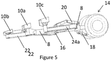
- FIG 3 shows a close-up of the landing gear of Figure 2 and a portion of the rear spar 12 of the wing 6 of Figure 2 .
- the landing gear 2 comprises an oleo strut 8, comprising a housing 8a and a piston 8b.
- the housing 8a is connected at its upper end to a central attachment point 10a, the central attachment point 10a being fixed to the rear spar 12 of the wing 6.
- a two-wheel axle 14 is connected to the lower end of the piston 8b.
- a cylindrical collar 16 is mounted on the housing 8a of the strut 8.
- a lower torque link 18 is pivotally connected at its lower end to the axle 14 and at its upper end to the strut 8, at the housing 8a.
- An upper torque link 20 is connected at its lower end to the strut 8, at the housing 8a and at its upper end to the collar 16.
- An outboard sidestay 22 is pivotally connected at its lower end to the collar 16. The upper end of the outboard sidestay 22 is pivotally connected to an outboard attachment point 10b.
- the outboard attachment point 10b is mounted on the spar 12 at a position outboard of the central attachment point 10a.
- the outboard sidestay 22 comprises a single member extending diagonally between the collar 16 and attachment point 10b.
- An inboard sidestay 24 is pivotally connected at its lower end to the collar 16. The upper end of the inboard sidestay 24 is pivotally connected to an inboard attachment point 10c.
- the inboard attachment point 10c is mounted on the spar 12 inboard of the central attachment point 10a and outboard attachment point 10b.
- the inboard sidestay 24 is hinged and comprises an upper member 24a and a lower member 24b.
- the upper member 24a is pivotally connected at its upper end to the inboard attachment point 10c, and at its lower end to the upper end of the lower member 24b.
- the lower member 24b is pivotally connected at its upper end to the lower end of the upper member 24a, and at its lower end to the collar 16.
- a linear actuator 26 is connected to a radially extending lug 28 on the upper end of the strut 8.
- Each of the attachment points 10a, 10b, 10c comprises a bearing (not shown in Fig. 1 ) which enables the upper end of the relevant sidestay 22, 24 or main strut 8 to rotate relative to the attachment point 10 about an axis that is substantially parallel to the longitudinal axis of the aircraft during retraction and/or deployment of the landing gear but prevents rotation about any other axis.
- a bearing not shown in Fig. 1
- the landing gear is locked such that none of the sidestays 22, 24 or main strut 8 can rotate about that axis.
- Means of achieving such locking are well known to the skilled person and will not be discussed further here.
- the main strut 8, inboard 24 and outboard 22 sidestay are constrained from rotating about an axis substantially parallel to the lateral axis of the aircraft such that the drag loads experienced by the landing gear will be transferred via all three of the main strut 8, inboard sidestay 24 and outboard sidestay 22 to the attachment points 10a, 10b, 10c.
- the major element of the lateral loads will be reacted by the inboard sidestay 24 and outboard sidestay 22, as a result of their triangular/v-shaped configuration, with an element of the lateral loads also being transferred via the main strut 8.
- the upper torque link 20 will act to transfer torque load from the main strut 8 to the sidestays 22, 24 via collar 16 for reaction at the outboard 10b and inboard 10c attachment points.
- landing gear in accordance with the present embodiment may distribute different components of the landing gear loads (e.g. drag loads, torque loads and vertical loads) to different attachment points on the aircraft, thereby reducing the maximum load experienced at the attachment points and reducing and/or eliminating the need for structural reinforcement at the attachment points.
- the landing gear loads e.g. drag loads, torque loads and vertical loads
- the central attachment point 10a may comprise a spherical bearing, which permits rotation of the main strut 8 about a central point in two orthogonal directions; around axes lying parallel to the longitudinal axis and the vertical axis of the aircraft 1, while otherwise preventing movement of the strut 8.
- torque loads cannot be transferred to the aircraft 1 via the first attachment point 10a due to the lack of constraint in the relevant direction. Instead the torque and drag loads are transferred to the aircraft 1 via the inboard 24 and outboard 22 sidestays only.
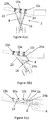
- Figures 4 (a), (b) and (c) show a front view of the landing gear of the first embodiment at various stages of the retraction process.
- the inboard 24 and outboard 22 sidestays each extend diagonally upwards and away from the collar forming a 'v' shape, with the strut 8 between them.
- the upper member 24(a) and lower member 24(b) of the inboard sidestay 24 are in line, such that the inboard sidestay 24 appears straight when viewed from the front in Figure 4(a) .
- the landing gear 2 is in an intermediate configuration, part way between the deployed and retracted configuration.
- the distal end of the landing gear 2 is located further inboard and the collar 16, to which the sidestays 22, 24 remain attached, is located high up the strut 8, further towards the underside of the wing 6, in comparison to Figure 4(a) .
- the outboard sidestay 22 has rotated inboard relative to the outboard attachment point 10b; the lower end of the outboard sidestay 22 is located inboard of the central attachment point 10a and the angle between the outboard sidestay 22 and the main strut 8 is reduced in comparison to the deployed position.
- the inboard sidestay 24 is partially folded in Figure 4(b) ; the point at which the upper 24a and lower 24b members meet is now located inboard of attachment point 10c and the lower member 24a lies perpendicular to the strut 8.
- FIG. 4(c) The outline of the underside of the wing and fuselage is denoted by a dashed line in Figure 4(c) .
- the landing gear is in the fully retracted position with the landing gear located within the envelope of the wing 4 and fuselage 5 of the aircraft 1.
- the collar 16 In the fully retracted position of Figure 4(c) the collar 16 has moved even further up the strut 8 and the outboard sidestay 22 lies alongside part of, and almost parallel to, the strut 8.
- the inboard sidestay 24 is folded with the lower member 24a lying at an acute angle to the upper member 24b.
- the linear actuator 26 exerts a force on the radial lug 28 (see Figure 3 ) to rotate the strut 8 on central attachment point 10a around an axis running substantially parallel to the longitudinal axis of the aircraft.
- the wheels of the landing gear 2 are consequently moved inboard and towards the centreline of the aircraft 1 until the landing gear 2 reaches the intermediate position shown in Figure 4(b) .
- the inward rotation of the strut 8 causes the single-piece outboard strut 22 to also rotate inwards, with the collar 16 sliding up the strut 8.
- the ends of the sidestays 22, 24 pivot about the point at which they are attached to the collar 16.
- embodiments in accordance with the present invention may allow for the retraction of the landing gear in a space efficient manner. Moreover, during the retraction process the incidental drag and torque loads are reacted via the inboard 24 and outboard 22 sidestays, thereby helping to control the locus of retraction.
- FIG. 6 shows a landing gear in accordance with a second example embodiment. Only those aspects of the second embodiment which differ with respect to the first embodiment will be discussed here. Like reference numerals denote like elements.
- the landing gear 102 of the third embodiment comprises a single-piece strut 108 connected at its distal end to a trailing linkage 130.
- the axle 104 is connected to the distal end of the trailing linkage 130.
- the collar 116 is mounted on the strut 108 as in the first embodiment.
- a shock absorber 132 is connected at one end to the trailing linkage 130 and at the other end to the collar 116.
- the shock absorber 132 damps the movement of the trailing linkage 130 relative to the strut 108.
- the distribution of the vertical loads between the main strut and the inboard and outboard sidestays may be varied during the design process by altering the position at which the shock absorber 132 is connected to the trailing linkage 130 and/or the location of the collar 116 along the length of the strut 108 when the landing gear is deployed.
- landing gear shown above have two-wheel axles, it will be appreciated that landing gear in accordance with the present invention may include a different number of wheels, for example a single wheel, or a larger number of wheels, for example four, six or eight wheels mounted on a bogie.
Landscapes
- Engineering & Computer Science (AREA)
- Mechanical Engineering (AREA)
- Aviation & Aerospace Engineering (AREA)
- Retarders (AREA)
- Tires In General (AREA)
Claims (15)
- Train d'atterrissage (2) d'aéronef (1) comprenant :une jambe principale (8), la jambe principale (8) pouvant être raccordée à un premier point de fixation (10a) positionné sur un aéronef (1);une contrefiche latérale intérieure (24), la contrefiche latérale intérieure (24) ayant une première extrémité raccordée à la jambe principale (8) pour le déplacement le long de la contrefiche principale, la contrefiche latérale intérieure (24) pouvant être raccordée au niveau d'une seconde extrémité, à un deuxième point de fixation (10b) situé sur l'aéronef (1);et une contrefiche latérale extérieure (22), la contrefiche latérale extérieure (22) ayant une première extrémité raccordée à la contrefiche latérale (8) pour le déplacement le long de la jambe principale (8), la contrefiche latérale extérieure (22) pouvant être raccordée au niveau d'une seconde extrémité, à un troisième point de fixation (10c) situé sur l'aéronef (1), etcaractérisé en ce qu'à l'usage, lorsque le train d'atterrissage (2) est dans une configuration déployée, le raccordement entre la première extrémité de chacune des contrefiches latérales intérieure et extérieure (24, 22) et la jambe principale (8), permet le déplacement de chaque première extrémité le long d'au moins une partie de la longueur de la jambe principale (8).
- Aéronef comprenant le train d'atterrissage selon la revendication 1.
- Aéronef selon la revendication 2, dans lequel le train d'atterrissage comprend un collier, le collier étant monté sur la jambe principale pour le déplacement le long de la contrefiche principale, et dans lequel la première extrémité de chacune des contrefiches latérales intérieure et extérieure est fixée au collier.
- Aéronef selon la revendication 2 ou 3, dans lequel le déplacement de la première extrémité de chacune des contrefiches latérales intérieure et extérieure n'est pas localement amorti de sorte que les contrefiches sont effectivement isolées des charges verticales de train d'atterrissage subies par la contrefiche principale.
- Aéronef selon la revendication 2 ou la revendication 3, dans lequel le train d'atterrissage comprend un ou plusieurs amortisseurs configurés de sorte qu'au moins une partie des charges verticales de train d'atterrissage subies par le train d'atterrissage est transmise à chaque contrefiche latérale via un amortisseur et facultativement, dans lequel une première extrémité de l'amortisseur est raccordée au collier, par exemple dans lequel le train d'atterrissage comprend une liaison de fuite et une seconde extrémité de l'amortisseur est raccordée à la liaison de fuite de sorte que les charges verticales de train d'atterrissage sont transmises de la liaison de fuite à chacune des contrefiches latérales intérieure et extérieure via l'amortisseur et le collier.
- Aéronef selon l'une quelconque des revendications 3 à 5, dans lequel le train d'atterrissage comprend un compas, le compas étant raccordé au niveau d'une première extrémité, à la jambe principale et au niveau d'une seconde extrémité, au collier, de sorte qu'à l'usage, lorsque le train d'atterrissage est dans la configuration déployée, les charges de couple subies par la jambe principale sont transmises à l'aéronef via le collier et les contrefiches latérales intérieure et extérieure.
- Aéronef selon l'une quelconque des revendications 2 à 6, dans lequel le train d'atterrissage est agencé de sorte qu'à l'usage, lorsque le train d'atterrissage est dans la configuration déployée, les charges de traînée sont transmises par les contrefiches latérales intérieure et extérieure pour la réaction au niveau des deuxième et troisième points de fixation respectivement et/ou les charges latérales sont transférées par le biais des contrefiches latérales intérieure et extérieure pour la réaction au niveau des deuxième et troisième points de fixation.
- Aéronef selon l'une quelconque des revendications 2 à 7, dans lequel les premier, deuxième et troisième points de fixation sont agencés sur une ligne droite, et facultativement dans lequel le train d'atterrissage est un train d'atterrissage principal.
- Aéronef selon l'une quelconque des revendications 2 à 8, dans lequel l'aéronef comprend une aile et les premier, deuxième et troisième points de fixation sont positionnés sur une structure faisant partie de l'aile, et facultativement dans lequel la structure comprend un longeron, par exemple un longeron composite.
- Aéronef selon l'une quelconque des revendications 2 à 9, dans lequel chacune parmi la contrefiche latérale intérieure, la contrefiche latérale extérieure et la jambe principale sont raccordées de manière pivotante au point de fixation approprié pour la rotation autour d'un axe sensiblement parallèle à l'axe longitudinal de l'aéronef pendant la rétraction et/ou le déploiement du train d'atterrissage, et facultativement, dans lequel la jambe principale est raccordée au premier point de fixation pour la rotation autour d'un point central dans deux axes orthogonaux pendant la rétraction et/ou le déploiement du train d'atterrissage ; le premier axe étant sensiblement parallèle à l'axe longitudinal de l'aéronef.
- Aéronef selon l'une quelconque des revendications 2 à 10, dans lequel la contrefiche latérale intérieure est de longueur variable et/ou la contrefiche latérale extérieure est de longueur fixe.
- Procédé pour répartir les charges de train d'atterrissage dans un aéronef (1) comprenant un train d'atterrissage (2) comprend une jambe principale (8), la jambe principale (8) étant raccordée à un premier point de fixation (10a) situé sur l'aéronef (1); une contrefiche latérale intérieure (24), la contrefiche latérale intérieure (24) ayant une première extrémité raccordée à la jambe principale (8), la contrefiche latérale intérieure (24) étant raccordée au niveau d'une seconde extrémité, à un deuxième point de fixation (10b) situé sur l'aéronef (1); et une contrefiche latérale extérieure (22), la contrefiche latérale extérieure (22) ayant une première extrémité raccordée à la jambe principale (8), la contrefiche latérale extérieure (22) étant raccordée, au niveau d'une seconde extrémité, à un troisième point de fixation (10c) situé sur l'aéronef (1), dans lequel, à l'usage, lorsque le train d'atterrissage (2) est dans la configuration déployée, le raccordement de la première extrémité de chacune des contrefiches latérales intérieure et extérieure (24, 22) permet le déplacement de la première extrémité verticalement par rapport à la jambe principale (8).
- Procédé selon la revendication 12, dans lequel la première extrémité de chacune des contrefiches intérieure et extérieure coulisse jusqu'à la jambe principale au fur et à mesure que le train d'atterrissage se rétracte.
- Procédé selon la revendication 12, dans lequel alors que le train d'atterrissage (2) est dans une configuration déployée, chacune parmi la jambe principale (8), la contrefiche latérale intérieure (24) et la contrefiche latérale extérieure (22) fournit une trajectoire de charge de train d'atterrissage séparée, par laquelle les charges de train d'atterrissage sont transférées à l'aéronef, et dans lequel le transfert des charges verticales de train d'atterrissage à l'aéronef (1) via les contrefiches latérales intérieure et extérieure (24, 22), est limité en permettant à la première extrémité de chacune des contrefiches latérales intérieure et extérieure (24, 22), une liberté de mouvement verticale par rapport à la contrefiche principale, et facultativement dans lequel le train d'atterrissage (2) comprend en outre au moins un amortisseur (132), et le au moins un amortisseur (132) fournit au moins une trajectoire de charge par laquelle les charges verticales de train d'atterrissage sont transférées de la jambe principale (8) à la contrefiche latérale intérieure (24) et à la contrefiche latérale extérieure (22).
- Procédé pour rétracter un train d'atterrissage (2) d'aéronef comprenant une jambe principale (8), la jambe principale (8) étant raccordée à un premier point de fixation (10a) situé sur un aéronef (1); une contrefiche latérale intérieure (24), la contrefiche latérale intérieure (24) étant raccordée au niveau d'une première extrémité, à la jambe principale (8) et au niveau d'une seconde extrémité, à un deuxième point de fixation (10b) situé sur l'aéronef (1) et une contrefiche latérale extérieure (22), la contrefiche latérale extérieure (22) étant raccordée, au niveau d'une première extrémité, à la jambe principale (8) et au niveau d'une seconde extrémité, à un troisième point de fixation (10c) situé sur l'aéronef (1), le procédé comprenant les étapes consistant à faire tourner la jambe principale (8) autour d'un axe sensiblement parallèle à l'axe longitudinal de l'aéronef (1); et dans lequel la première extrémité de chacune des contrefiches latérales intérieure et extérieure (24, 22) coulisse jusqu'à la jambe principale (8) au fur et à mesure que la contrefiche tourne, et facultativement dans lequel la longueur de la contrefiche latérale intérieure (24) se réduit au fur et à mesure que le train d'atterrissage (2) se rétracte.
Applications Claiming Priority (2)
| Application Number | Priority Date | Filing Date | Title |
|---|---|---|---|
| GB1610538.9A GB2551380A (en) | 2016-06-16 | 2016-06-16 | Aircraft landing gear |
| PCT/GB2017/051693 WO2017216528A1 (fr) | 2016-06-16 | 2017-06-09 | Train d'atterrissage d'aéronef |
Publications (2)
| Publication Number | Publication Date |
|---|---|
| EP3472047A1 EP3472047A1 (fr) | 2019-04-24 |
| EP3472047B1 true EP3472047B1 (fr) | 2019-11-20 |
Family
ID=56894998
Family Applications (1)
| Application Number | Title | Priority Date | Filing Date |
|---|---|---|---|
| EP17730908.5A Active EP3472047B1 (fr) | 2016-06-16 | 2017-06-09 | Train d'atterrissage d'aéronef |
Country Status (5)
| Country | Link |
|---|---|
| US (1) | US11377205B2 (fr) |
| EP (1) | EP3472047B1 (fr) |
| CN (1) | CN109311534B (fr) |
| GB (1) | GB2551380A (fr) |
| WO (1) | WO2017216528A1 (fr) |
Families Citing this family (11)
| Publication number | Priority date | Publication date | Assignee | Title |
|---|---|---|---|---|
| GB2563826A (en) * | 2017-06-19 | 2019-01-02 | Airbus Operations Ltd | Landing Gear |
| US11260965B2 (en) | 2019-04-15 | 2022-03-01 | The Boeing Company | Aircraft landing gear forward trunnion support assemblies and related methods |
| EP3725671B1 (fr) * | 2019-04-15 | 2023-09-27 | Safran Landing Systems UK Ltd | Aéronef ayant un train d'atterrissage à stabilisateur |
| GB2584412A (en) * | 2019-05-20 | 2020-12-09 | Airbus Operations Ltd | Landing gear assembly |
| US12260773B1 (en) * | 2020-05-19 | 2025-03-25 | Erik Kysar | Flight training and landing assistant |
| CN112173083B (zh) * | 2020-09-25 | 2023-01-31 | 中国直升机设计研究所 | 一种尾起落架连接接头 |
| GB2611099A (en) | 2021-09-28 | 2023-03-29 | Airbus Operations Ltd | Landing gear stay |
| GB2618849A (en) * | 2022-05-20 | 2023-11-22 | Airbus Operations Ltd | Aircraft landing gear |
| US12397905B1 (en) | 2024-06-24 | 2025-08-26 | American Honda Motor Co., Inc. | Locking system for aircraft landing gear bay doors |
| GB2642264A (en) * | 2024-06-28 | 2026-01-07 | Airbus Operations Ltd | A commercial airliner |
| CN119460085A (zh) * | 2024-12-23 | 2025-02-18 | 中国航空工业集团公司西安飞机设计研究所 | 一种用于大型桁架式起落架的三角支撑结构 |
Family Cites Families (15)
| Publication number | Priority date | Publication date | Assignee | Title |
|---|---|---|---|---|
| FR793094A (fr) * | 1935-03-22 | 1936-01-15 | Aeroplanes Morane Saulnier | Articulation perfectionnée |
| GB510290A (en) * | 1938-07-01 | 1939-07-31 | Fairey Aviat Co Ltd | Improvements in or relating to aircraft landing gear |
| GB527191A (en) * | 1939-04-03 | 1940-10-03 | Boulton Aircraft Ltd | Improvements relating to retractible undercarriages for aircraft |
| GB632110A (en) * | 1947-12-03 | 1949-11-16 | Electro Hydraulics Ltd | Improvements in or relating to undercarriage suspension for aircraft |
| US2668030A (en) * | 1948-12-15 | 1954-02-02 | Curtiss Wright Corp | Aircraft landing gear lock |
| US4328939A (en) * | 1979-12-26 | 1982-05-11 | The Boeing Company | Airplane main landing gear assembly |
| US4345727A (en) * | 1979-12-26 | 1982-08-24 | The Boeing Company | Body-braced main airplane landing gear |
| US4392623A (en) * | 1980-12-22 | 1983-07-12 | The Boeing Company | Fused connection adapted to fail under different overloads acting in different directions |
| EP0564772A1 (fr) * | 1992-04-07 | 1993-10-13 | Deutsche Aerospace Airbus Gesellschaft mit beschränkter Haftung | Train d'atterrissage principal pour un avion avec centre de gravité en arrière |
| GB9921379D0 (en) * | 1999-09-10 | 1999-11-10 | British Aerospace | Aircraft landing gear |
| US6651931B1 (en) * | 2002-09-04 | 2003-11-25 | The Boeing Company | Multi-positional landing gear assemblies |
| US7416156B2 (en) * | 2004-08-30 | 2008-08-26 | Messier-Dowty (Usa), Inc. | Dual brace-determinate landing gear |
| GB2428650B (en) * | 2005-08-04 | 2011-01-12 | Messier Dowty Ltd | Landing gear |
| FR2893588B1 (fr) * | 2005-11-21 | 2008-02-01 | Airbus France Sas | Case de train a structure en caissons |
| GB0716675D0 (en) | 2007-08-29 | 2007-10-03 | Airbus Uk Ltd | Aircraft landing gear assembly |
-
2016
- 2016-06-16 GB GB1610538.9A patent/GB2551380A/en not_active Withdrawn
-
2017
- 2017-06-09 US US16/310,002 patent/US11377205B2/en active Active
- 2017-06-09 CN CN201780037575.2A patent/CN109311534B/zh active Active
- 2017-06-09 WO PCT/GB2017/051693 patent/WO2017216528A1/fr not_active Ceased
- 2017-06-09 EP EP17730908.5A patent/EP3472047B1/fr active Active
Non-Patent Citations (1)
| Title |
|---|
| None * |
Also Published As
| Publication number | Publication date |
|---|---|
| GB201610538D0 (en) | 2016-08-03 |
| WO2017216528A1 (fr) | 2017-12-21 |
| EP3472047A1 (fr) | 2019-04-24 |
| GB2551380A (en) | 2017-12-20 |
| CN109311534A (zh) | 2019-02-05 |
| US20190135416A1 (en) | 2019-05-09 |
| CN109311534B (zh) | 2022-07-15 |
| US11377205B2 (en) | 2022-07-05 |
Similar Documents
| Publication | Publication Date | Title |
|---|---|---|
| EP3472047B1 (fr) | Train d'atterrissage d'aéronef | |
| US10654562B2 (en) | Landing gear | |
| EP2277774B1 (fr) | Train d'atterrissage articulé escamotable | |
| US4328939A (en) | Airplane main landing gear assembly | |
| US4345727A (en) | Body-braced main airplane landing gear | |
| US10766607B2 (en) | Landing gear | |
| EP2470423B1 (fr) | Train d'atterrissage principal équipé d'une entretoise arrière rigide | |
| EP2679488A1 (fr) | Système de train d'atterrissage à semi-levier | |
| US11945575B2 (en) | Landing gear assembly | |
| US20210253228A1 (en) | Modular landing gear | |
| US20130313360A1 (en) | Landing gear for an aircraft | |
| WO2025260174A1 (fr) | Redressement de trains d'atterrissage principaux par biellettes universelles | |
| GB2592204A (en) | Modular landing gear |
Legal Events
| Date | Code | Title | Description |
|---|---|---|---|
| STAA | Information on the status of an ep patent application or granted ep patent |
Free format text: STATUS: UNKNOWN |
|
| STAA | Information on the status of an ep patent application or granted ep patent |
Free format text: STATUS: THE INTERNATIONAL PUBLICATION HAS BEEN MADE |
|
| PUAI | Public reference made under article 153(3) epc to a published international application that has entered the european phase |
Free format text: ORIGINAL CODE: 0009012 |
|
| STAA | Information on the status of an ep patent application or granted ep patent |
Free format text: STATUS: REQUEST FOR EXAMINATION WAS MADE |
|
| 17P | Request for examination filed |
Effective date: 20190115 |
|
| AK | Designated contracting states |
Kind code of ref document: A1 Designated state(s): AL AT BE BG CH CY CZ DE DK EE ES FI FR GB GR HR HU IE IS IT LI LT LU LV MC MK MT NL NO PL PT RO RS SE SI SK SM TR |
|
| AX | Request for extension of the european patent |
Extension state: BA ME |
|
| GRAP | Despatch of communication of intention to grant a patent |
Free format text: ORIGINAL CODE: EPIDOSNIGR1 |
|
| STAA | Information on the status of an ep patent application or granted ep patent |
Free format text: STATUS: GRANT OF PATENT IS INTENDED |
|
| DAX | Request for extension of the european patent (deleted) | ||
| INTG | Intention to grant announced |
Effective date: 20190531 |
|
| DAV | Request for validation of the european patent (deleted) | ||
| GRAS | Grant fee paid |
Free format text: ORIGINAL CODE: EPIDOSNIGR3 |
|
| GRAA | (expected) grant |
Free format text: ORIGINAL CODE: 0009210 |
|
| STAA | Information on the status of an ep patent application or granted ep patent |
Free format text: STATUS: THE PATENT HAS BEEN GRANTED |
|
| AK | Designated contracting states |
Kind code of ref document: B1 Designated state(s): AL AT BE BG CH CY CZ DE DK EE ES FI FR GB GR HR HU IE IS IT LI LT LU LV MC MK MT NL NO PL PT RO RS SE SI SK SM TR |
|
| REG | Reference to a national code |
Ref country code: GB Ref legal event code: FG4D |
|
| REG | Reference to a national code |
Ref country code: CH Ref legal event code: EP |
|
| REG | Reference to a national code |
Ref country code: DE Ref legal event code: R096 Ref document number: 602017008952 Country of ref document: DE |
|
| REG | Reference to a national code |
Ref country code: IE Ref legal event code: FG4D |
|
| REG | Reference to a national code |
Ref country code: AT Ref legal event code: REF Ref document number: 1203902 Country of ref document: AT Kind code of ref document: T Effective date: 20191215 |
|
| REG | Reference to a national code |
Ref country code: NL Ref legal event code: MP Effective date: 20191120 |
|
| REG | Reference to a national code |
Ref country code: LT Ref legal event code: MG4D |
|
| PG25 | Lapsed in a contracting state [announced via postgrant information from national office to epo] |
Ref country code: SE Free format text: LAPSE BECAUSE OF FAILURE TO SUBMIT A TRANSLATION OF THE DESCRIPTION OR TO PAY THE FEE WITHIN THE PRESCRIBED TIME-LIMIT Effective date: 20191120 Ref country code: LV Free format text: LAPSE BECAUSE OF FAILURE TO SUBMIT A TRANSLATION OF THE DESCRIPTION OR TO PAY THE FEE WITHIN THE PRESCRIBED TIME-LIMIT Effective date: 20191120 Ref country code: NL Free format text: LAPSE BECAUSE OF FAILURE TO SUBMIT A TRANSLATION OF THE DESCRIPTION OR TO PAY THE FEE WITHIN THE PRESCRIBED TIME-LIMIT Effective date: 20191120 Ref country code: LT Free format text: LAPSE BECAUSE OF FAILURE TO SUBMIT A TRANSLATION OF THE DESCRIPTION OR TO PAY THE FEE WITHIN THE PRESCRIBED TIME-LIMIT Effective date: 20191120 Ref country code: GR Free format text: LAPSE BECAUSE OF FAILURE TO SUBMIT A TRANSLATION OF THE DESCRIPTION OR TO PAY THE FEE WITHIN THE PRESCRIBED TIME-LIMIT Effective date: 20200221 Ref country code: NO Free format text: LAPSE BECAUSE OF FAILURE TO SUBMIT A TRANSLATION OF THE DESCRIPTION OR TO PAY THE FEE WITHIN THE PRESCRIBED TIME-LIMIT Effective date: 20200220 Ref country code: FI Free format text: LAPSE BECAUSE OF FAILURE TO SUBMIT A TRANSLATION OF THE DESCRIPTION OR TO PAY THE FEE WITHIN THE PRESCRIBED TIME-LIMIT Effective date: 20191120 Ref country code: BG Free format text: LAPSE BECAUSE OF FAILURE TO SUBMIT A TRANSLATION OF THE DESCRIPTION OR TO PAY THE FEE WITHIN THE PRESCRIBED TIME-LIMIT Effective date: 20200220 |
|
| PG25 | Lapsed in a contracting state [announced via postgrant information from national office to epo] |
Ref country code: HR Free format text: LAPSE BECAUSE OF FAILURE TO SUBMIT A TRANSLATION OF THE DESCRIPTION OR TO PAY THE FEE WITHIN THE PRESCRIBED TIME-LIMIT Effective date: 20191120 Ref country code: RS Free format text: LAPSE BECAUSE OF FAILURE TO SUBMIT A TRANSLATION OF THE DESCRIPTION OR TO PAY THE FEE WITHIN THE PRESCRIBED TIME-LIMIT Effective date: 20191120 Ref country code: IS Free format text: LAPSE BECAUSE OF FAILURE TO SUBMIT A TRANSLATION OF THE DESCRIPTION OR TO PAY THE FEE WITHIN THE PRESCRIBED TIME-LIMIT Effective date: 20200320 |
|
| PG25 | Lapsed in a contracting state [announced via postgrant information from national office to epo] |
Ref country code: AL Free format text: LAPSE BECAUSE OF FAILURE TO SUBMIT A TRANSLATION OF THE DESCRIPTION OR TO PAY THE FEE WITHIN THE PRESCRIBED TIME-LIMIT Effective date: 20191120 |
|
| PG25 | Lapsed in a contracting state [announced via postgrant information from national office to epo] |
Ref country code: CZ Free format text: LAPSE BECAUSE OF FAILURE TO SUBMIT A TRANSLATION OF THE DESCRIPTION OR TO PAY THE FEE WITHIN THE PRESCRIBED TIME-LIMIT Effective date: 20191120 Ref country code: RO Free format text: LAPSE BECAUSE OF FAILURE TO SUBMIT A TRANSLATION OF THE DESCRIPTION OR TO PAY THE FEE WITHIN THE PRESCRIBED TIME-LIMIT Effective date: 20191120 Ref country code: EE Free format text: LAPSE BECAUSE OF FAILURE TO SUBMIT A TRANSLATION OF THE DESCRIPTION OR TO PAY THE FEE WITHIN THE PRESCRIBED TIME-LIMIT Effective date: 20191120 Ref country code: PT Free format text: LAPSE BECAUSE OF FAILURE TO SUBMIT A TRANSLATION OF THE DESCRIPTION OR TO PAY THE FEE WITHIN THE PRESCRIBED TIME-LIMIT Effective date: 20200412 Ref country code: DK Free format text: LAPSE BECAUSE OF FAILURE TO SUBMIT A TRANSLATION OF THE DESCRIPTION OR TO PAY THE FEE WITHIN THE PRESCRIBED TIME-LIMIT Effective date: 20191120 Ref country code: ES Free format text: LAPSE BECAUSE OF FAILURE TO SUBMIT A TRANSLATION OF THE DESCRIPTION OR TO PAY THE FEE WITHIN THE PRESCRIBED TIME-LIMIT Effective date: 20191120 |
|
| REG | Reference to a national code |
Ref country code: AT Ref legal event code: MK05 Ref document number: 1203902 Country of ref document: AT Kind code of ref document: T Effective date: 20191120 |
|
| REG | Reference to a national code |
Ref country code: DE Ref legal event code: R097 Ref document number: 602017008952 Country of ref document: DE |
|
| PG25 | Lapsed in a contracting state [announced via postgrant information from national office to epo] |
Ref country code: SK Free format text: LAPSE BECAUSE OF FAILURE TO SUBMIT A TRANSLATION OF THE DESCRIPTION OR TO PAY THE FEE WITHIN THE PRESCRIBED TIME-LIMIT Effective date: 20191120 Ref country code: SM Free format text: LAPSE BECAUSE OF FAILURE TO SUBMIT A TRANSLATION OF THE DESCRIPTION OR TO PAY THE FEE WITHIN THE PRESCRIBED TIME-LIMIT Effective date: 20191120 |
|
| PLBE | No opposition filed within time limit |
Free format text: ORIGINAL CODE: 0009261 |
|
| STAA | Information on the status of an ep patent application or granted ep patent |
Free format text: STATUS: NO OPPOSITION FILED WITHIN TIME LIMIT |
|
| 26N | No opposition filed |
Effective date: 20200821 |
|
| PG25 | Lapsed in a contracting state [announced via postgrant information from national office to epo] |
Ref country code: AT Free format text: LAPSE BECAUSE OF FAILURE TO SUBMIT A TRANSLATION OF THE DESCRIPTION OR TO PAY THE FEE WITHIN THE PRESCRIBED TIME-LIMIT Effective date: 20191120 Ref country code: PL Free format text: LAPSE BECAUSE OF FAILURE TO SUBMIT A TRANSLATION OF THE DESCRIPTION OR TO PAY THE FEE WITHIN THE PRESCRIBED TIME-LIMIT Effective date: 20191120 |
|
| PG25 | Lapsed in a contracting state [announced via postgrant information from national office to epo] |
Ref country code: IT Free format text: LAPSE BECAUSE OF FAILURE TO SUBMIT A TRANSLATION OF THE DESCRIPTION OR TO PAY THE FEE WITHIN THE PRESCRIBED TIME-LIMIT Effective date: 20191120 Ref country code: MC Free format text: LAPSE BECAUSE OF FAILURE TO SUBMIT A TRANSLATION OF THE DESCRIPTION OR TO PAY THE FEE WITHIN THE PRESCRIBED TIME-LIMIT Effective date: 20191120 |
|
| REG | Reference to a national code |
Ref country code: CH Ref legal event code: PL |
|
| PG25 | Lapsed in a contracting state [announced via postgrant information from national office to epo] |
Ref country code: SI Free format text: LAPSE BECAUSE OF FAILURE TO SUBMIT A TRANSLATION OF THE DESCRIPTION OR TO PAY THE FEE WITHIN THE PRESCRIBED TIME-LIMIT Effective date: 20191120 |
|
| PG25 | Lapsed in a contracting state [announced via postgrant information from national office to epo] |
Ref country code: LU Free format text: LAPSE BECAUSE OF NON-PAYMENT OF DUE FEES Effective date: 20200609 |
|
| REG | Reference to a national code |
Ref country code: BE Ref legal event code: MM Effective date: 20200630 |
|
| PG25 | Lapsed in a contracting state [announced via postgrant information from national office to epo] |
Ref country code: CH Free format text: LAPSE BECAUSE OF NON-PAYMENT OF DUE FEES Effective date: 20200630 Ref country code: LI Free format text: LAPSE BECAUSE OF NON-PAYMENT OF DUE FEES Effective date: 20200630 Ref country code: IE Free format text: LAPSE BECAUSE OF NON-PAYMENT OF DUE FEES Effective date: 20200609 |
|
| PG25 | Lapsed in a contracting state [announced via postgrant information from national office to epo] |
Ref country code: BE Free format text: LAPSE BECAUSE OF NON-PAYMENT OF DUE FEES Effective date: 20200630 |
|
| PG25 | Lapsed in a contracting state [announced via postgrant information from national office to epo] |
Ref country code: TR Free format text: LAPSE BECAUSE OF FAILURE TO SUBMIT A TRANSLATION OF THE DESCRIPTION OR TO PAY THE FEE WITHIN THE PRESCRIBED TIME-LIMIT Effective date: 20191120 Ref country code: MT Free format text: LAPSE BECAUSE OF FAILURE TO SUBMIT A TRANSLATION OF THE DESCRIPTION OR TO PAY THE FEE WITHIN THE PRESCRIBED TIME-LIMIT Effective date: 20191120 Ref country code: CY Free format text: LAPSE BECAUSE OF FAILURE TO SUBMIT A TRANSLATION OF THE DESCRIPTION OR TO PAY THE FEE WITHIN THE PRESCRIBED TIME-LIMIT Effective date: 20191120 |
|
| PG25 | Lapsed in a contracting state [announced via postgrant information from national office to epo] |
Ref country code: MK Free format text: LAPSE BECAUSE OF FAILURE TO SUBMIT A TRANSLATION OF THE DESCRIPTION OR TO PAY THE FEE WITHIN THE PRESCRIBED TIME-LIMIT Effective date: 20191120 |
|
| PGFP | Annual fee paid to national office [announced via postgrant information from national office to epo] |
Ref country code: DE Payment date: 20250618 Year of fee payment: 9 |
|
| PGFP | Annual fee paid to national office [announced via postgrant information from national office to epo] |
Ref country code: GB Payment date: 20250618 Year of fee payment: 9 |
|
| PGFP | Annual fee paid to national office [announced via postgrant information from national office to epo] |
Ref country code: FR Payment date: 20250625 Year of fee payment: 9 |