EP3473105B1 - Thread dispensing device - Google Patents
Thread dispensing device Download PDFInfo
- Publication number
- EP3473105B1 EP3473105B1 EP17197262.3A EP17197262A EP3473105B1 EP 3473105 B1 EP3473105 B1 EP 3473105B1 EP 17197262 A EP17197262 A EP 17197262A EP 3473105 B1 EP3473105 B1 EP 3473105B1
- Authority
- EP
- European Patent Office
- Prior art keywords
- thread
- dispensing device
- unit
- tubular
- transport
- Prior art date
- Legal status (The legal status is an assumption and is not a legal conclusion. Google has not performed a legal analysis and makes no representation as to the accuracy of the status listed.)
- Active
Links
Images


Classifications
-
- A—HUMAN NECESSITIES
- A22—BUTCHERING; MEAT TREATMENT; PROCESSING POULTRY OR FISH
- A22C—PROCESSING MEAT, POULTRY, OR FISH
- A22C11/00—Sausage making ; Apparatus for handling or conveying sausage products during manufacture
- A22C11/12—Apparatus for tying sausage skins ; Clipping sausage skins
- A22C11/127—Forming a suspension loop
-
- A—HUMAN NECESSITIES
- A22—BUTCHERING; MEAT TREATMENT; PROCESSING POULTRY OR FISH
- A22C—PROCESSING MEAT, POULTRY, OR FISH
- A22C11/00—Sausage making ; Apparatus for handling or conveying sausage products during manufacture
- A22C11/02—Sausage filling or stuffing machines
-
- A—HUMAN NECESSITIES
- A22—BUTCHERING; MEAT TREATMENT; PROCESSING POULTRY OR FISH
- A22C—PROCESSING MEAT, POULTRY, OR FISH
- A22C11/00—Sausage making ; Apparatus for handling or conveying sausage products during manufacture
- A22C11/12—Apparatus for tying sausage skins ; Clipping sausage skins
- A22C11/122—Apparatus for tying sausage skins ; Clipping sausage skins by forming knots
-
- A—HUMAN NECESSITIES
- A22—BUTCHERING; MEAT TREATMENT; PROCESSING POULTRY OR FISH
- A22C—PROCESSING MEAT, POULTRY, OR FISH
- A22C11/00—Sausage making ; Apparatus for handling or conveying sausage products during manufacture
- A22C11/12—Apparatus for tying sausage skins ; Clipping sausage skins
- A22C11/125—Apparatus for tying sausage skins ; Clipping sausage skins by clipping; Removal of clips
-
- B—PERFORMING OPERATIONS; TRANSPORTING
- B65—CONVEYING; PACKING; STORING; HANDLING THIN OR FILAMENTARY MATERIAL
- B65H—HANDLING THIN OR FILAMENTARY MATERIAL, e.g. SHEETS, WEBS, CABLES
- B65H51/00—Forwarding filamentary material
- B65H51/02—Rotary devices, e.g. with helical forwarding surfaces
- B65H51/04—Rollers, pulleys, capstans, or intermeshing rotary elements
- B65H51/08—Rollers, pulleys, capstans, or intermeshing rotary elements arranged to operate in groups or in co-operation with other elements
- B65H51/10—Rollers, pulleys, capstans, or intermeshing rotary elements arranged to operate in groups or in co-operation with other elements with opposed coacting surfaces, e.g. providing nips
-
- B—PERFORMING OPERATIONS; TRANSPORTING
- B65—CONVEYING; PACKING; STORING; HANDLING THIN OR FILAMENTARY MATERIAL
- B65H—HANDLING THIN OR FILAMENTARY MATERIAL, e.g. SHEETS, WEBS, CABLES
- B65H57/00—Guides for filamentary materials; Supports therefor
Definitions
- the present invention relates to a dispensing device for dispensing thread in a clipping machine for producing sausage-shaped products according to claim 1 and a method for dispensing thread according to claim 11.
- the present invention further relates to a clipping machine for producing sausage-shaped products, which includes a dispensing device for dispensing thread according to claim 10 and a method for producing sausage-shaped products according to claim 13.
- filaments or ribbons are used, e.g. when being attached to a product as a suspension element or a handle for manipulating the product.
- the filament or ribbon may also become part of the product or could be the product itself, like a string of adhesive, e.g. hot melt adhesive, or a plastic string processed in a 3D-printer.
- the term “thread” is used as a representative for filaments, ribbons or any other longitudinally extending string-shaped elements or the like.
- thread dispensing devices can be used, is the production of sausage-shaped products or sausages, in particular ring-shaped sausages.
- the front end of a thread is attached to the front end of a tubular casing to be filled with a filling material, by a closure clip which closes the front end of said tubular casing and which is attached via closing means.
- a closure clip which closes the front end of said tubular casing and which is attached via closing means.
- a defined length of thread is dispensed or fed, respectively.
- the tubular casing forms a ring or at least a segment of a ring.
- the rear end of the filed tubular casing is gathered by gathering means and closed by a further closure clip via said closing means.
- the thread is caught by the gathering means and attached to the rear end of the ring-shaped sausage by said closure clip.
- the ring-shaped sausage just produced and provided with the thread connecting both ends of said sausage is cut-off from the remaining supply of tubular casing and supply of thread, respectively.
- a string or thread feeder disclosed in EP 0 872 184 A1 has a thread drive including two toothed wheels between which the thread is arranged for being fed, with one of the toothed wheels driven by a pneumatic actuated rocker arm. A retraction of the thread already dispensed, is enabled by an additional pneumatic piston/cylinder arrangement.
- the thread is also used for closing the front end as well as the rear end of the tubular casing.
- the filled tubular casing is gathered and the thread is fed to the gathered portion.
- a knot is formed and closed about said gathered portion.
- a machine for producing sausage-shaped products in which a thread is forwarded to the gathered portion of a filled tubular casing.
- the thread is fed by a motor into a closing region of the machine at which a knot is formed and tightly closed by a thread pulling mechanism.
- a device for dispensing or feeding a thread in a clipping machine for producing sausage-shaped products comprising a transport unit having at least a first and a second transport element for a defined transport of a thread, a drive unit for driving the first and second transport element and a shifting unit for reversibly shifting the first transport element relative to the second transport element.
- thread or a thread is transported by driving the first and second transport elements with the thread positioned there between.
- the transport of the thread is carried out actively.
- the thread may be inserted or removed from the thread dispensing device.
- the thread transport may be started or stopped or interrupted, independently from the operation state of the drive unit, e.g. in an emergency case.
- the first and second transport elements are at least approximately cylindrical rollers having rotation axes which are arranged parallel to each other. Moreover, the rollers have preferably and at least approximately the same diameter.
- This specific design enables the processing of various kinds of thread or thread material, e.g. of different diameter or cross-sectional shape or different quality. Thereby, not only thread of round cross-section may be processed, but also thread with a rectangular cross-section or ribbon. Moreover, the danger of the thread escaping from the transport unit is reduced.
- rollers of the transport unit like plastic or metal, e.g. dependent on the kind of thread to be treated.
- first and second transport elements may be provided with a surface coating, e.g. rubber, for further enhancing the transportation properties.
- the shifting unit includes guide means for reversibly guiding the first transport element preferably in a common vertical plane away from and back to the second guide element.
- the first transport element is shifted at least approximately parallel to the second transport element or is shifted along a trajectory.
- the guide means ensures that the transport of thread may be started or stopped without damaging the thread, namely by preventing slip between the rollers and the thread as well as preventing wear. Thereby, the reliability of the production process in which the inventive thread dispensing device is used, is improved.
- the transportation unit is coupled to the drive unit via a gear unit.
- the transportation speed may be set to a base level.
- the gear unit may be designed such that both, the first and the second transport element, are driven at identical speeds. This prevents slippage between the first and the second transport element, and thus, also slippage between one of the drive elements and the thread being transported. Thereby, a careful transport of thread is enabled, without damaging the thread.
- the drive unit includes a stepper motor controlled by a control unit.
- a stepper motor allows feeding any defined length of thread.
- different programs may be stored in said control unit, on the basis of which the stepper motor may be operated.
- thread may be retracted by the thread dispensing device, if necessary, and about one or more defined lengths, according to the respective program.
- control unit of the inventive thread dispensing device may be arranged at various locations. In a simple case, the control unit is integrated in the thread dispensing device. It is also possible that the control unit of the thread dispensing device is integrated in the control unit of a machine which uses the inventive thread dispensing device, like a clipping machine.
- a switch unit for selecting a predefined operation mode is provided at said device.
- This switch unit may be integrated in the control unit of the thread dispensing device, or may be arranged separately, for example to be reached easily by an operator. Naturally, the switch unit may also be integrated in the control unit of a machine which uses the inventive thread dispensing device, like a clipping machine.
- the inventive thread dispensing device may further comprise a guide unit for guiding a thread through the dispensing device.
- the guide unit ensures the correct supply of thread to the transport unit of the thread dispensing device, particularly to the first and second transport element, and a defined lead out of thread from the thread dispensing device to a subsequent machine.
- the thread dispensing device may be provided with a cutting device for cutting the thread.
- the cutting device may be a manually operated cutting device which, in the simplest case, is a blade arranged at a frame element of the dispensing device.
- the cutting device allows an operator to cut-off the thread just used, e.g. at the end of the production process, or when a thread different from that presently used is selected for the further process, or to remove defective portions from the currently used thread, like weak points or knots.
- the cutting device is arranged downstream the transport unit, referred to the thread transport or feeding direction.
- the shifting means for reversibly shifting the first transport element relative to the second transport element may be of any suitable construction.
- the shifting means may include automatic actuation means, like an additional motor that may be controlled by a respective program stored in the control unit of the thread dispensing device.
- the shifting means include a manually operable lever. This allows a compact design of the thread dispensing device with a reduced control effort.
- a clipping machine for producing sausage-shaped products, like sausages, with a tubular or bag-shaped packaging casing containing a flowable filling material and a suspension element attached to the tubular or bag-shaped casing, wherein the suspension element consists of thread.
- the clipping machine comprises a filling tube on which the tubular or bag-shaped packaging casing is stored and through which filling material is fed in a feeding direction into the tubular or bag-shaped packaging casing, gathering means for gathering the filled tubular or bag-shaped packaging casing and for forming a plait-like portion thereto and a clipping device for applying at least one closure means, like a closure clip, to the plait-like portion for closing the just filled portion of the tubular or bag-shaped packaging casing.
- the clipping machine further comprises a device for dispensing thread according to the present invention.
- the thread dispensing device is arranged in an area above the clipping device.
- the thread dispensing device can be arranged below the clipping device or in a neighborhood to the clipping device.
- a method for dispensing thread by a thread dispensing device in a clipping machine for producing sausage-shaped products including the steps of:
- the present invention also provides a method for producing sausage-shaped products, like sausages, with a tubular or bag-shaped packaging casing containing a flowable filling material and a suspension element attached to the tubular or bag-shaped casing, wherein the suspension element consists of thread, including the steps of:
- the method further comprises the step of guiding thread through a guide unit of the dispensing device.
- the method may also comprise the step of selecting a predefined operation mode for operating the thread dispensing device.
- the clipping machine equipped with the thread dispensing device according to the present invention, the method for producing sausage-shaped products as well as the method for dispensing thread provide all advantages as explained in conjunction with the inventive thread dispensing device alone.
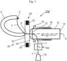
- a clipping machine CM for producing sausage-shaped products S shown schematically in Fig. 1 comprises, as main components, a filling tube 10 having a longitudinally and horizontally extending center axis A, with a discharge opening for discharging a filling material at its left end 12 and a feeding opening for feeding in a feeding direction F the filling material to the discharge opening of filling tube 10, for example by a feeding pump (not shown), at its right end 14, and a casing brake assembly 16 arranged coaxially with filling tube 10 in the region of the left end 12 of filling tube 10.
- Filling tube 10 is made of a suitable material, like stainless steel.
- a supply of tubular packaging casing M made of a thin sheet material is stored on filling tube 10. From the supply of tubular packaging casing M, tubular packaging casing M is pulled-off during the process of manufacturing the sausage-shaped products S, in particular by the feeding pressure for filling the filling material into tubular packaging casing M.
- Clipping machine CM further comprises a clipping device 20 for closing a filled tubular packaging casing M by applying closure means, like closure clips C, to a plait-like portion P, and gathering means 30 for gathering the filled tubular packaging casing M and for forming said plait-like portion P thereto.
- closure means like closure clips C
- gathering means 30 for gathering the filled tubular packaging casing M and for forming said plait-like portion P thereto.
- clipping device 20 is positioned immediately downstream left end 12 of filling tube 10, and coaxially aligned to filling tube 10.
- Clipping device 20 comprises a first and a second clipping tool 22, 24 formed by a punch 22 and a die 24. It has to be noted that punch 22 and die 24 may apply and close a single closure clip C for closing the just filled tubular packaging casing M, or may apply and close two closure clips C at the same time, a first closure clip C for closing the rear end of the just filled tubular packaging casing M for forming a sausage-shaped product S, and a second closure clip C for closing the front end of a tubular packaging casing M subsequently to be filled.
- Gathering means 30 include a first displacer unit 32 and a second displacer unit 34, wherein first displacer unit 32 is positioned downstream second displacer unit 34.
- First and second clipping tools 22, 24 of clipping device 20 may be positioned between first and second displacer units 32, 34, at least for applying and closing one or two closure clips C to plait-like portion P.
- a discharge device For discharging a sausage-shaped product S just produced from clipping machine CM, downstream clipping device 20, a discharge device may be arranged, which may comprise a conveyor belt and guide rollers. In a simple case, the discharge device may be a chute.
- ring-shaped sausage products may be produced.
- a thread T is dispensed to clipping machine CM by a device for dispensing a thread or a thread dispensing device DD in a dispensing direction D.
- Thread dispensing device DD can be arranged below filling tube 10 or clipping device 20. In another arrangement of thread dispensing device DD, it can be provided above filling tube 10 or clipping device 20. The latter allows a more easy operation of the device DD by an operator.
- Thread T is attached to the front end of the tubular packaging casing M to be filled by a closure clip C that closes the front end of tubular packaging casing M.
- Thread T dispensed or fed by thread dispensing device DD to clipping machine CM is received from a supply of thread T or thread supply TS, like a spool, transported through thread dispensing device DD and guided or fed into the closing region of clipping machine CM, in which gathering means 30 and clipping device 20 are arranged for gathering and closing the filled tubular packaging casing M.
- the supply of thread may be also arranged above or below filling tube 10 and/or clipping device 20.
- the feeding of the thread can be started before the filling process begins.
- the thread can form a loop which is suspended during the filling of the sausage-shaped product.
- the feeding of the thread can be started simultaneously with the beginning of the filling process.
- a length of thread T is dispensed by thread dispensing device DD, that is shorter than the length of tubular packaging casing M which forms a complete sausage-shaped product S. Accordingly, after a length of tubular packaging casing material M which matches the length of the suspended thread T, is filled, the tubular packaging casing M while further being filled, forms a ring, as can be seen in Fig. 1 .
- gathering means 30 gather the filled tubular packaging casing M, and form a plait-like portion P thereto.
- first displacer unit 32 is moved relative to second displacer unit 34 in feeding direction F along center axis A of filling tube 10, for forming an elongated plait-like portion P
- a second length of thread T which corresponds to the length of the elongated plait-like portion, may be dispensed by thread dispensing device DD.
- thread dispensing device DD may retract thread T about a defined length such that the remaining length of thread T between the front end and the rear end of sausage-shaped product S matches a predetermined length of thread T.
- clipping device 20 places and closes at least one closure clip C at plait-like portion P, for closing the rear end of just filled tubular packaging casing M forming a ring.
- closure clip C thread T is fixed to the rear end of the just filled tubular packaging casing M.
- Clipping device 20 may simultaneously place and close a second closure Clip C at plait-like portion P for closing the front end of the next tubular packaging casing M subsequently to be filled, and for fixing thread T thereto.
- Thread T and plait-like portion P are cut upstream closure clip C that closes filled tubular packaging casing M for separating sausage-shaped product S just produced from the remaining supply of tubular packaging casing M and thread T. Sausage-shaped product S may than be removed from clipping machine CM by a respective discharge device.
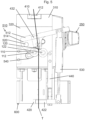
- Figs. 2 and 3 show an embodiment of a dispensing device for dispensing thread, or thread dispensing device DD.
- Thread dispensing device DD comprises a transport unit 100 for transporting thread T, a drive unit 200 for driving transport unit 100, a gear unit 300 for transmitting torque from drive unit 200 to transport unit 100, guide means 400 for guiding thread T through thread dispensing device DD and a shifting unit 500 for reversibly interrupting the transport of thread T.
- Thread dispensing device T according to Figs. 2 and 3 further comprises a switch unit 250 for manipulating drive unit 200.
- the components of thread dispensing device DD are supported by a frame work 600 by which thread dispensing device DD may be mounted to a clipping machine CM.
- Clipping machine CM can be a new or an already existing machine. In other words, thread dispensing device DD can also be a retrofitting kit for existing machines.
- Drive unit 200 includes an electric motor 210, like a stepper motor, connected to a control unit and a respective power source by a connector unit 220 (cf. Fig. 3 ). Motor 210 and connector unit 220 are covered by a motor coverage 230 as shown in Fig. 2 . Motor 210 has a drive shaft 212 that extends into gear unit 300.
- Gear unit 300 comprises a gear coverage 310 and a carrier plate 320 for rotatably supporting the movable elements of gear unit 300, like rotation shafts with respective toothed wheels thereon, as it can particularly seen in Fig. 3 where gear box coverage 310 has been omitted, and as it is explained in detail in conjunction with Fig. 4 below.
- Transport unit 100 includes a first cylindrical drive roller 110 and a second cylindrical drive roller 120, the rotation axes of which are arranged parallel to each other in a substantially horizontal plane. Rollers 110, 120 are arranged on rotatably supported shafts 112, 122.
- Rollers 110, 120 are in a transport position, in which they abut each other along a horizontal contact line.
- a thread T when positioned between rollers 110, 120, is forwarded when rollers 110, 120 are driven by drive unit 200.
- Shifting unit 500 comprises a shifting element or lever 510 having a plate-shaped actuation portion 512 that extends substantially horizontal and along the left side of carrier plate 320 towards the front side of thread dispensing device DD as shown in Fig. 2 .
- actuation portion 512 of shifting element or lever 510 two lugs 514 extend downwardly from actuation portion 512, parallel to each other and to carrier plate 320, and with a gap between lugs 514 that corresponds to the axial length of drive rollers 110, 120 of transport unit 100 (cf. Fig. 3 ).
- Shifting unit 500 further comprises a pivot shaft 520 that extends horizontally through carrier plate 320 in which shaft 520 is rotatably supported.
- Lever 510 is mounted to the portion of shaft 520 that extends over carrier plate 320, to be reversibly pivoted about the longitudinal axis of shaft 520.
- In the region of the lower ends of lugs 514 horizontally arranged and coaxially aligned holes are provided through which shaft 112 of transport unit 100 extends into gear unit 300.
- a guide means or guide slot 540 is arranged, which has the shape of a circular segment with a center point coinciding with the longitudinal axis of shaft 520. This enables shaft 112 to be pivoted about shaft 520 and in parallel orientation thereto, upon reversible actuation of lever 510. In other words, shaft 112 is moved on an at least substantially circular-shaped trajectory around shaft 520.
- Guide means 400 for guiding thread T through thread dispensing device DD include an upper guide element 410 coupled to the upper side of gear box coverage 310, in a recess having a shape that corresponds to the shape of guide element 410, and extends leftwards in Fig. 2 .
- plate-like guide element 410 has a vertical through-hole 412 aligned approximately vertically above the contact line of rollers 110, 120 of transport unit 100.
- a lower guide element 420 of guide means 400 is arranged with a through-hole 422 aligned preferably and at least approximately with through-hole 412 of guide element 410 and the contact line between rollers 110, 120.
- Guide element 420 is mounted to carrier plate 320 by a vertically arranged plate-like holder 440.
- a guide hole 432 is provided and preferably aligned with through-hole 412 of guide element 410, the contact line between rollers 110, 120 and through-hole 422 of guide element 420.
- Guide element 410 with hole 412, guide hole 432 in lever 510 and guide element 420 with hole 422 form guide means 400 for guiding thread T through thread dispensing device DD, as can be seen in Fig. 5 which is a schematic sectional view through guide means 400 of thread dispensing device DD along the guide path of thread T.
- lever 510 For interrupting the transport or feeding of thread T, lever 510 may be pushed downwardly on its end at which pneumatic spring 330 is attached (cf. Fig. 3 ), for example by an operator, whereby first roller 110 is shifted about the pivot axis or shaft 520 of lever 510 along guide slot 540 and away from second roller 120 into a release position.
- Return member or pneumatic spring 530 acts on lever 510 such that, when lever 510 is released by the operator, lever 510 and first roller 110 are automatically be shifted back into the transport position as shown in Figs. 2 and 3 .
- a cutting device or cutter unit 700 is provided at plate-like holder 440 which can in particular be seen in Fig. 2 .
- Cutter unit 700 is arranged below or downstream of transport unit 100, referred to the feeding or dispensing direction of thread T which is oriented from upper guide element 410 to lower guide element 420, and includes a blade holder 710 which is fixed to plate-like holder 440.
- Blade holder 710 has a vertically extending slot 712.
- a blade 720 is clamped between blade holder 710 and plate-like holder 440 such that a sharpened edge of blade 720 extends into slot 712.
- Cutter unit 700 may be used for example by an operator for cutting thread T, e.g. when exchanging thread T by another kind of thread T, for cleaning the free end of thread T before inserting it into thread dispensing device DD, or for removing defective portions of thread T.
- Fig. 4 is a sectional view through gear unit 300 of thread dispensing device DD viewed from stepper motor 210.
- gear unit 300 further comprises a pinion 330, a first intermediate gearwheel 332, a second intermediate gearwheel 334, a first drive gearwheel 336 and a second drive gearwheel 338.
- Pinion 330 is arranged at that portion of shaft 212 of motor 210 which extends into gear unit 300, and engages first intermediate gearwheel 332 that is arranged on a shaft 333 which is rotatably supported by carrier plate 320.
- First intermediate gearwheel 332 engages second intermediate gearwheel 334 rotatably arranged at pivot shaft 520 of shifting means 500, and first drive gearwheel 336 on shaft 122 of transport unit 100.
- Second intermediate gearwheel 334 engages second drive gearwheel 338 mounted on shaft 112 of transport unit 100.
- pinion 330 when clockwise driven by motor 210, drives first intermediate gearwheel 332 counterclockwise.
- First intermediate gearwheel 332 in turn rotates second intermediate gearwheel 334 and first drive gearwheel 336 in clockwise direction. Accordingly, second drive gearwheel 338 is rotated counterclockwise by second intermediate gearwheel 334.
- First roller 110 of transport unit 100 is mounted on shaft 112 driven by second drive gearwheel 338, and second roller 120 is mounted on shaft 122 driven by first drive gearwheel 336.
- second roller 120 is mounted on shaft 122 driven by first drive gearwheel 336.
- tubular packaging casing M is stored on filling tube 10.
- the front end of tubular packaging casing M is closed by a closure clip C, and the front end of thread T is fixed to the front end of tubular casing M by said closure clip C.
- thread T is pulled by an operator from thread supply TS and is threaded in upper guide element 410. Thread T is then pulled further by the operator to transport elements 110, 120 and is guided therebetween wherein transport element 110 is shifted away from transport element 120 via pushing lever 510 downwardly by the operator. When thread T is positioned between transport elements 110, 120, the operator releases lever 510 so that transport element 110 comes in contact once again with transport element 120. Finally, thread T is threaded through lower guide element 420 and is fed to the closing region of clipping machine CM.
- a predefined length of thread is dispensed by thread dispensing device DD. Thereafter, the transport of thread T is stopped and thread T is clamped in thread dispensing device DD, e.g. by first and second rollers 110, 120, for preventing thread from being further pulled-off from thread supply TS.
- the filling process is continued until a desired portion of filling material has been fed through filling tube 10 into tubular packaging casing M, or the filled tubular packaging casing M has a desired length.
- the filled tubular packaging casing reaches a length that corresponds to the length of thread T dispensed by thread dispensing device DD, and the front end of the filled tubular casing M is held in its position relative to filling tube 10.
- filled tubular packaging M forms a ring or at least a segment of a ring.
- clipping device 20 places and closes two closure clips C to plait-like portion P, a first closure clip C for closing the rear end of filled tubular casing M, and a second closure clip C for closing the front end of the tubular casing material M subsequently to be filled. Thereafter, plait-like portion P and thread T are cut by a respective cutting device between the two closure clips C for separating sausage-shaped product S from the remaining tubular packaging casing M and from the supply of thread T.
- thread T is fixed to the respective end of tubular packaging casing M by said closure clip C.
- thread T may be pulled back by thread dispensing device DD about a respective length, after filled tubular casing M has been gathered by gathering means 30, but before a closure clip C has been placed and closed at plait-like portion P by clipping device 20.
- an elongated plait-like portion P to the filled tubular packaging casing M, e.g. for producing slack filled sausages.
- displacer unit 32 of gathering means 30 positioned downstream displacer unit 34 is moved in feeding direction F away from displacer unit 34 in a spreading operation, thereby, an elongated plait-like portion P is formed to filled tubular packaging M.
- an additional length of thread T may be dispensed by thread dispensing device DD.
- This additional length corresponds to the length of the spreading path about which displacer unit 32 is moved away from displacer unit 34.
- the casing material is preserved, since possible friction between thread T and tubular packaging casing M during the spreading operation is prevented.
- Thread dispensing device DD includes a motor 210 which may be a stepper motor, and a control unit for controlling motor 210.
- the control unit may be provided with a large number of programs for controlling motor 210, e.g. the dispensing speed, the dispensed length, or the number of lengths dispensed during one production cycle. Accordingly, thread dispensing device DD may be adapted to a great variety of products to be produced on clipping machine M.
- the control unit of thread dispensing device DD may be incorporated in thread dispensing device DD, such that it may work independently from clipping machine CM, or only needs to be provided with a signal corresponding to the start of a production cycle, or the production process at all. Thread dispensing device DD, after the receipt of a respective start signal, may than operate independent from clipping machine CM and on the basis of a selected program stored in the control unit of thread dispensing device DD.
- control unit of thread dispensing device DD may also be incorporated in clipping machine CM.
- a program for controlling thread dispensing device DD may automatically be selected by clipping machine CM.
- the operator may manually select a program for controlling thread dispensing device DD at the control unit of clipping machine CM.
- selecting switch 250 is provided at thread dispensing device DD for selecting only the length of thread T to be dispensed, and an operator starts and stops thread dispensing device DD for each production cycle.
- thread dispensing device DD may also designed to receive a start or stop signal from the control unit of clipping machine CM, and the operator selects the length of thread T to be dispensed by switch 250.
- switch 250 may be used for setting other parameters, like the length of breaks between two subsequent dispensing operations.
- Switch 250 may also be used for setting thread dispensing device DD into or out of operation.
- parameters of thread dispensing device DD may also varied during the production process by switch 250, e.g. in adaption to varying properties of tubular packaging casing M or thread T.
- the first and second roller 110, 120 of transport unit 100 are both driven by drive unit 200. Thereby, slip is prevented between thread T and one of rollers 110, 120, and wear is prevented and thread T is surely transported straight through transport unit 100.
- shifting unit 500 enables the removal of first roller 110 from second roller 120, without interrupting the drive of first roller 110, since second drive gearwheel 338 stays in engagement with second intermediate gearwheel 334 while first roller 110 is moved away from second roller 120.
- lever 510 rotates about shaft 520.
- Shaft 112 with first roller thereon, is moved along a circular path about shaft 520 and within guide slot 540 in carrier plate 320.
- second drive gearwheel 338 at shaft 122 also rotates about shaft 520 which also carries second intermediate gearwheel 334 which is engaged with second drive gear wheel 338.
- Thread T in the sense of the present invention may be any longitudinally extending material, like strings, filaments or ribbons.
- the design of thread dispensing device DD allows the transport of thread of various materials and cross-section.
- flat material which may be attached to a tubular packaging of a respective product, like a tubular net for producing netted fruits or any other netted items.
- the ribbon attached to such a net product may form a handle.
- a ribbon may also be used a label with information regarding the packaged product printed thereon.
- thread dispensing device DD is mounted to a clipping machine CM such that thread T may be dispensed into the closing region of clipping machine CM, where gathering means 30 and clipping device 20 are arranged.
- Thread dispensing device DD may be arranged above or below the closing region of clipping machine CM, as long as an operator may securely operate thread dispensing device DD and thread T is reliably dispensed to clipping machine CM.
- respective guide elements like guide rollers, may be provided for guiding thread T dispensed by thread dispensing device DD into the closing region of clipping machine CM for accurately being grasped by gathering means 30.
- Return member 530 has been described as being a pneumatic spring including a piston/cylinder arrangement with pressurized gas in the cylinder, for automatically pushing lever 510, and thus, transport unit 100 into its operation position, after being manually actuated.
- the return member may automatically be actuated, e.g. including a separate drive, like an electric or pneumatic drive, and being controlled by a program for controlling thread dispensing device DD.
- the respective control program may include steps for interrupting the transport of thread T, or to start the transport of thread T. Accordingly, it is also possible to establish an emergency routine which automatically interrupts the transport of thread T in emergency case.
Landscapes
- Life Sciences & Earth Sciences (AREA)
- Engineering & Computer Science (AREA)
- Wood Science & Technology (AREA)
- Zoology (AREA)
- Food Science & Technology (AREA)
- Processing Of Meat And Fish (AREA)
- Containers And Plastic Fillers For Packaging (AREA)
- Meat, Egg Or Seafood Products (AREA)
Description
- The present invention relates to a dispensing device for dispensing thread in a clipping machine for producing sausage-shaped products according to claim 1 and a method for dispensing thread according to claim 11. The present invention further relates to a clipping machine for producing sausage-shaped products, which includes a dispensing device for dispensing thread according to
claim 10 and a method for producing sausage-shaped products according to claim 13. - In various production processes, filaments or ribbons are used, e.g. when being attached to a product as a suspension element or a handle for manipulating the product. The filament or ribbon may also become part of the product or could be the product itself, like a string of adhesive, e.g. hot melt adhesive, or a plastic string processed in a 3D-printer. In all these cases, it is necessary to dispense or feed, respectively, the filament, ribbon or string with a defined speed and in predetermined lengths according to the product to be produced and/or specific process parameters.
- In the following, the term "thread" is used as a representative for filaments, ribbons or any other longitudinally extending string-shaped elements or the like.
- One exemplary field in which thread dispensing devices can be used, is the production of sausage-shaped products or sausages, in particular ring-shaped sausages. For producing such ring-shaped sausages, the front end of a thread is attached to the front end of a tubular casing to be filled with a filling material, by a closure clip which closes the front end of said tubular casing and which is attached via closing means. During the filling of the tubular casing, a defined length of thread is dispensed or fed, respectively. By continuing the filling of the tubular casing and holding or detaining the thread, the tubular casing forms a ring or at least a segment of a ring. After the ring-shaped sausage has reached a predefined size or form, respectively, the rear end of the filed tubular casing is gathered by gathering means and closed by a further closure clip via said closing means. The thread is caught by the gathering means and attached to the rear end of the ring-shaped sausage by said closure clip. Subsequently, the ring-shaped sausage just produced and provided with the thread connecting both ends of said sausage, is cut-off from the remaining supply of tubular casing and supply of thread, respectively.
- A string or thread feeder disclosed in
EP 0 872 184 A1 , has a thread drive including two toothed wheels between which the thread is arranged for being fed, with one of the toothed wheels driven by a pneumatic actuated rocker arm. A retraction of the thread already dispensed, is enabled by an additional pneumatic piston/cylinder arrangement. - In other machines for producing sausage-shaped products, the thread is also used for closing the front end as well as the rear end of the tubular casing. In such machines, the filled tubular casing is gathered and the thread is fed to the gathered portion. A knot is formed and closed about said gathered portion.
- From
DE 41 15 994 A1 , a machine for producing sausage-shaped products is known in which a thread is forwarded to the gathered portion of a filled tubular casing. The thread is fed by a motor into a closing region of the machine at which a knot is formed and tightly closed by a thread pulling mechanism. - It is an object of the present invention to provide a dispensing device and a method for dispensing thread which may be used in various applications, and which may easily be adapted to a specific application and to various process parameters. It is a further object of the present invention to provide a method and a clipping machine for producing sausage-shaped products which includes the inventive dispensing device for dispensing thread.
- According to the present invention, there is provided a device for dispensing or feeding a thread in a clipping machine for producing sausage-shaped products, comprising a transport unit having at least a first and a second transport element for a defined transport of a thread, a drive unit for driving the first and second transport element and a shifting unit for reversibly shifting the first transport element relative to the second transport element.
- In the inventive device for dispensing thread, or the inventive thread dispensing device, thread or a thread is transported by driving the first and second transport elements with the thread positioned there between. Thus, the transport of the thread is carried out actively. When reversibly shifting the first transport element relative to the second transport element, the thread may be inserted or removed from the thread dispensing device. Moreover, the thread transport may be started or stopped or interrupted, independently from the operation state of the drive unit, e.g. in an emergency case.
- In a preferred embodiment of the inventive thread dispensing device, the first and second transport elements are at least approximately cylindrical rollers having rotation axes which are arranged parallel to each other. Moreover, the rollers have preferably and at least approximately the same diameter. This specific design enables the processing of various kinds of thread or thread material, e.g. of different diameter or cross-sectional shape or different quality. Thereby, not only thread of round cross-section may be processed, but also thread with a rectangular cross-section or ribbon. Moreover, the danger of the thread escaping from the transport unit is reduced.
- It has to be noted that various kinds of material may be used for the rollers of the transport unit, like plastic or metal, e.g. dependent on the kind of thread to be treated.
- Additionally, the first and second transport elements may be provided with a surface coating, e.g. rubber, for further enhancing the transportation properties.
- In a further preferred embodiment of the inventive thread dispensing device, the shifting unit includes guide means for reversibly guiding the first transport element preferably in a common vertical plane away from and back to the second guide element. In preferred arrangements, the first transport element is shifted at least approximately parallel to the second transport element or is shifted along a trajectory. The guide means ensures that the transport of thread may be started or stopped without damaging the thread, namely by preventing slip between the rollers and the thread as well as preventing wear. Thereby, the reliability of the production process in which the inventive thread dispensing device is used, is improved.
- Advantageously, the transportation unit is coupled to the drive unit via a gear unit. By means of the gear unit, the transportation speed may be set to a base level.
- Additionally, the gear unit may be designed such that both, the first and the second transport element, are driven at identical speeds. This prevents slippage between the first and the second transport element, and thus, also slippage between one of the drive elements and the thread being transported. Thereby, a careful transport of thread is enabled, without damaging the thread.
- Further advantageously, the drive unit includes a stepper motor controlled by a control unit. The use of a stepper motor allows feeding any defined length of thread. Furthermore, since the stepper motor is controlled by a control unit, different programs may be stored in said control unit, on the basis of which the stepper motor may be operated. Thus, it is possible to feed only one length of thread or more than one different lengths of thread. Also, thread may be retracted by the thread dispensing device, if necessary, and about one or more defined lengths, according to the respective program.
- The control unit of the inventive thread dispensing device may be arranged at various locations. In a simple case, the control unit is integrated in the thread dispensing device. It is also possible that the control unit of the thread dispensing device is integrated in the control unit of a machine which uses the inventive thread dispensing device, like a clipping machine.
- It is further possible to change the dispensing program also during the production process, e.g. during the production of two subsequent products. This allows the adaption of the production, e.g. to fluctuating features of the thread, product components, or the production machine.
- For an easy and rapid change of the program of the thread dispensing device, a switch unit for selecting a predefined operation mode is provided at said device. This switch unit may be integrated in the control unit of the thread dispensing device, or may be arranged separately, for example to be reached easily by an operator. Naturally, the switch unit may also be integrated in the control unit of a machine which uses the inventive thread dispensing device, like a clipping machine.
- The inventive thread dispensing device may further comprise a guide unit for guiding a thread through the dispensing device. The guide unit ensures the correct supply of thread to the transport unit of the thread dispensing device, particularly to the first and second transport element, and a defined lead out of thread from the thread dispensing device to a subsequent machine.
- Additionally, the thread dispensing device may be provided with a cutting device for cutting the thread. The cutting device may be a manually operated cutting device which, in the simplest case, is a blade arranged at a frame element of the dispensing device. The cutting device allows an operator to cut-off the thread just used, e.g. at the end of the production process, or when a thread different from that presently used is selected for the further process, or to remove defective portions from the currently used thread, like weak points or knots. In a preferred embodiment, the cutting device is arranged downstream the transport unit, referred to the thread transport or feeding direction.
- The shifting means for reversibly shifting the first transport element relative to the second transport element may be of any suitable construction. The shifting means may include automatic actuation means, like an additional motor that may be controlled by a respective program stored in the control unit of the thread dispensing device. In a preferred embodiment, the shifting means include a manually operable lever. This allows a compact design of the thread dispensing device with a reduced control effort.
- Furthermore, there is provided a clipping machine for producing sausage-shaped products, like sausages, with a tubular or bag-shaped packaging casing containing a flowable filling material and a suspension element attached to the tubular or bag-shaped casing, wherein the suspension element consists of thread. The clipping machine comprises a filling tube on which the tubular or bag-shaped packaging casing is stored and through which filling material is fed in a feeding direction into the tubular or bag-shaped packaging casing, gathering means for gathering the filled tubular or bag-shaped packaging casing and for forming a plait-like portion thereto and a clipping device for applying at least one closure means, like a closure clip, to the plait-like portion for closing the just filled portion of the tubular or bag-shaped packaging casing. The clipping machine further comprises a device for dispensing thread according to the present invention. In a preferred embodiment, the thread dispensing device is arranged in an area above the clipping device. Of course, the thread dispensing device can be arranged below the clipping device or in a neighborhood to the clipping device.
- Further according to the present invention, there is provided a method for dispensing thread by a thread dispensing device in a clipping machine for producing sausage-shaped products, including the steps of:
- providing a supply of thread,
- feeding thread by at least a first and second transport element of a transport unit of the thread dispensing device, and
- reversibly shifting the first transport element relative to the second transport element for transporting thread or for interrupting the feeding of thread.
- The present invention also provides a method for producing sausage-shaped products, like sausages, with a tubular or bag-shaped packaging casing containing a flowable filling material and a suspension element attached to the tubular or bag-shaped casing, wherein the suspension element consists of thread, including the steps of:
- feeding filling material through a filling tube in a feeding direction into the tubular or bag-shaped packaging casing,
- gathering the filled tubular or bag-shaped packaging casing and forming a plait-like portion thereto,
- applying at least one closure means, like a closure clip, to the plait-like portion for closing the just filled portion of the tubular or bag-shaped packaging casing,
- feeding thread by at least a first and second transport element of a transport unit of a thread dispensing device in a transportation direction, and
- reversibly shifting the first transport element relative to the second transport element for transporting thread or for interrupting the feeding of thread.
- The method further comprises the step of guiding thread through a guide unit of the dispensing device.
- The method may also comprise the step of selecting a predefined operation mode for operating the thread dispensing device.
- The clipping machine equipped with the thread dispensing device according to the present invention, the method for producing sausage-shaped products as well as the method for dispensing thread provide all advantages as explained in conjunction with the inventive thread dispensing device alone.
- Further advantages and preferred embodiments of the present invention will be described in the following together with the drawings listed below. The expressions "left", "right", "below" and "above" used in the following description, are referred to the drawings in an alignment such that the reference numbers and the notation of the figures used can be read in normal orientation.
- Fig. 1:
- is a schematic view showing the principal design of a clipping machine;
- Fig. 2:
- is a schematic and perspective view to the front side of a thread dispensing device according to the present invention;
- Fig. 3:
- is a schematic and perspective view to the rear side of the thread dispensing device as shown in
Fig. 2 ; - Fig. 4:
- is a sectional view through the gear unit of the thread dispensing device as shown in
Fig. 2 ; and - Fig. 5:
- is a schematic sectional view through the guide means of the thread dispensing device as shown in
Fig. 2 , along the guide path of the thread. - A clipping machine CM for producing sausage-shaped products S shown schematically in
Fig. 1 , comprises, as main components, a fillingtube 10 having a longitudinally and horizontally extending center axis A, with a discharge opening for discharging a filling material at itsleft end 12 and a feeding opening for feeding in a feeding direction F the filling material to the discharge opening of fillingtube 10, for example by a feeding pump (not shown), at itsright end 14, and acasing brake assembly 16 arranged coaxially with fillingtube 10 in the region of theleft end 12 of fillingtube 10. Fillingtube 10 is made of a suitable material, like stainless steel. A supply of tubular packaging casing M made of a thin sheet material is stored on fillingtube 10. From the supply of tubular packaging casing M, tubular packaging casing M is pulled-off during the process of manufacturing the sausage-shaped products S, in particular by the feeding pressure for filling the filling material into tubular packaging casing M. - Clipping machine CM further comprises a
clipping device 20 for closing a filled tubular packaging casing M by applying closure means, like closure clips C, to a plait-like portion P, and gathering means 30 for gathering the filled tubular packaging casing M and for forming said plait-like portion P thereto. These components are all arranged downstream fillingtube 10. - As can be inferred from
Fig. 1 , clippingdevice 20 is positioned immediately downstreamleft end 12 of fillingtube 10, and coaxially aligned to fillingtube 10. Clippingdevice 20 comprises a first and asecond clipping tool punch 22 and adie 24. It has to be noted thatpunch 22 and die 24 may apply and close a single closure clip C for closing the just filled tubular packaging casing M, or may apply and close two closure clips C at the same time, a first closure clip C for closing the rear end of the just filled tubular packaging casing M for forming a sausage-shaped product S, and a second closure clip C for closing the front end of a tubular packaging casing M subsequently to be filled. Gathering means 30 include afirst displacer unit 32 and asecond displacer unit 34, whereinfirst displacer unit 32 is positioned downstreamsecond displacer unit 34. First andsecond clipping tools device 20 may be positioned between first andsecond displacer units - For discharging a sausage-shaped product S just produced from clipping machine CM,
downstream clipping device 20, a discharge device may be arranged, which may comprise a conveyor belt and guide rollers. In a simple case, the discharge device may be a chute. - In the clipping machine CM according to
Fig. 1 , ring-shaped sausage products may be produced. For forming tubular packaging casing M into a ring shape while being filled, a thread T is dispensed to clipping machine CM by a device for dispensing a thread or a thread dispensing device DD in a dispensing direction D. - Thread dispensing device DD can be arranged below filling
tube 10 or clippingdevice 20. In another arrangement of thread dispensing device DD, it can be provided above fillingtube 10 or clippingdevice 20. The latter allows a more easy operation of the device DD by an operator. - Thread T is attached to the front end of the tubular packaging casing M to be filled by a closure clip C that closes the front end of tubular packaging casing M. Thread T dispensed or fed by thread dispensing device DD to clipping machine CM is received from a supply of thread T or thread supply TS, like a spool, transported through thread dispensing device DD and guided or fed into the closing region of clipping machine CM, in which gathering means 30 and
clipping device 20 are arranged for gathering and closing the filled tubular packaging casing M. The supply of thread may be also arranged above or below fillingtube 10 and/or clippingdevice 20. - The feeding of the thread can be started before the filling process begins. In such a case, the thread can form a loop which is suspended during the filling of the sausage-shaped product. Alternatively, the feeding of the thread can be started simultaneously with the beginning of the filling process.
- During the filling tubular packaging casing M, a length of thread T is dispensed by thread dispensing device DD, that is shorter than the length of tubular packaging casing M which forms a complete sausage-shaped product S. Accordingly, after a length of tubular packaging casing material M which matches the length of the suspended thread T, is filled, the tubular packaging casing M while further being filled, forms a ring, as can be seen in
Fig. 1 . - After the desired length of tubular packaging casing M is filled, gathering means 30 gather the filled tubular packaging casing M, and form a plait-like portion P thereto.
- In specific cases, in which
first displacer unit 32 is moved relative tosecond displacer unit 34 in feeding direction F along center axis A of fillingtube 10, for forming an elongated plait-like portion P, a second length of thread T which corresponds to the length of the elongated plait-like portion, may be dispensed by thread dispensing device DD. - In the case that the dispensed length of thread T that extends between the front end of sausage-shaped product S and its rear end, is longer than a desired length, thread dispensing device DD may retract thread T about a defined length such that the remaining length of thread T between the front end and the rear end of sausage-shaped product S matches a predetermined length of thread T.
- After thread T extending between the front end and the rear end of sausage-shaped product S has the predetermined length, clipping
device 20 places and closes at least one closure clip C at plait-like portion P, for closing the rear end of just filled tubular packaging casing M forming a ring. By said closure clip C, thread T is fixed to the rear end of the just filled tubular packaging casing M. - Clipping
device 20 may simultaneously place and close a second closure Clip C at plait-like portion P for closing the front end of the next tubular packaging casing M subsequently to be filled, and for fixing thread T thereto. - Thread T and plait-like portion P are cut upstream closure clip C that closes filled tubular packaging casing M for separating sausage-shaped product S just produced from the remaining supply of tubular packaging casing M and thread T. Sausage-shaped product S may than be removed from clipping machine CM by a respective discharge device.
-
Figs. 2 and3 show an embodiment of a dispensing device for dispensing thread, or thread dispensing device DD. - Thread dispensing device DD comprises a
transport unit 100 for transporting thread T, adrive unit 200 for drivingtransport unit 100, agear unit 300 for transmitting torque fromdrive unit 200 to transportunit 100, guide means 400 for guiding thread T through thread dispensing device DD and a shiftingunit 500 for reversibly interrupting the transport of thread T. Thread dispensing device T according toFigs. 2 and3 further comprises aswitch unit 250 for manipulatingdrive unit 200. The components of thread dispensing device DD are supported by aframe work 600 by which thread dispensing device DD may be mounted to a clipping machine CM. Clipping machine CM can be a new or an already existing machine. In other words, thread dispensing device DD can also be a retrofitting kit for existing machines. -
Drive unit 200 includes anelectric motor 210, like a stepper motor, connected to a control unit and a respective power source by a connector unit 220 (cf.Fig. 3 ).Motor 210 andconnector unit 220 are covered by amotor coverage 230 as shown inFig. 2 .Motor 210 has adrive shaft 212 that extends intogear unit 300. -
Gear unit 300 comprises agear coverage 310 and acarrier plate 320 for rotatably supporting the movable elements ofgear unit 300, like rotation shafts with respective toothed wheels thereon, as it can particularly seen inFig. 3 wheregear box coverage 310 has been omitted, and as it is explained in detail in conjunction withFig. 4 below. -
Transport unit 100 includes a firstcylindrical drive roller 110 and a secondcylindrical drive roller 120, the rotation axes of which are arranged parallel to each other in a substantially horizontal plane.Rollers shafts -
Rollers Figs. 2 ,3 and5 , are in a transport position, in which they abut each other along a horizontal contact line. A thread T when positioned betweenrollers rollers drive unit 200. - Shifting
unit 500 comprises a shifting element orlever 510 having a plate-shapedactuation portion 512 that extends substantially horizontal and along the left side ofcarrier plate 320 towards the front side of thread dispensing device DD as shown inFig. 2 . At the rear end ofactuation portion 512 of shifting element orlever 510, twolugs 514 extend downwardly fromactuation portion 512, parallel to each other and tocarrier plate 320, and with a gap betweenlugs 514 that corresponds to the axial length ofdrive rollers Fig. 3 ). - Shifting
unit 500 further comprises apivot shaft 520 that extends horizontally throughcarrier plate 320 in whichshaft 520 is rotatably supported.Lever 510 is mounted to the portion ofshaft 520 that extends overcarrier plate 320, to be reversibly pivoted about the longitudinal axis ofshaft 520. In the region of the lower ends oflugs 514, horizontally arranged and coaxially aligned holes are provided through whichshaft 112 oftransport unit 100 extends intogear unit 300. Incarrier plate 320, a guide means or guideslot 540 is arranged, which has the shape of a circular segment with a center point coinciding with the longitudinal axis ofshaft 520. This enablesshaft 112 to be pivoted aboutshaft 520 and in parallel orientation thereto, upon reversible actuation oflever 510. In other words,shaft 112 is moved on an at least substantially circular-shaped trajectory aroundshaft 520. -
Transport unit 100 further includes asupport plate 140 arranged parallel tocarrier plate 320 ofgear unit 300, on its left side inFig. 2 and with a gap therebetween that corresponds to the width oflever 510.Support plate 140 rotatably supports the left end ofshaft 122 oftransport unit 100 and the left end ofshaft 520 of shiftingunit 500. InFig. 3 ,support plate 140 has been omitted such that the left ends ofshafts - Guide means 400 for guiding thread T through thread dispensing device DD include an
upper guide element 410 coupled to the upper side ofgear box coverage 310, in a recess having a shape that corresponds to the shape ofguide element 410, and extends leftwards inFig. 2 . At its left end, plate-like guide element 410 has a vertical through-hole 412 aligned approximately vertically above the contact line ofrollers transport unit 100. Belowrollers lower guide element 420 of guide means 400 is arranged with a through-hole 422 aligned preferably and at least approximately with through-hole 412 ofguide element 410 and the contact line betweenrollers Guide element 420 is mounted tocarrier plate 320 by a vertically arranged plate-like holder 440. - Additionally, in
actuation portion 512 oflever 510 of shiftingunit 500, aguide hole 432 is provided and preferably aligned with through-hole 412 ofguide element 410, the contact line betweenrollers hole 422 ofguide element 420. -
Guide element 410 withhole 412,guide hole 432 inlever 510 and guideelement 420 withhole 422 form guide means 400 for guiding thread T through thread dispensing device DD, as can be seen inFig. 5 which is a schematic sectional view through guide means 400 of thread dispensing device DD along the guide path of thread T. - As particularly can be seen in
Fig. 2 , areturn member 530 is arranged between the front end ofactuation portion 512 oflever 510 and the front end ofguide element 420.Return member 530, in the embodiment ofFigs. 2 and3 , is a pneumatic spring including a piston/cylinder arrangement with pressurized gas in the cylinder. InFigs. 2 and3 ,lever 510, and thus,rollers rollers rollers 110, 120 (cf.Fig. 5 ), is forwarded whendrive 200 is actuated. - For interrupting the transport or feeding of thread T,
lever 510 may be pushed downwardly on its end at whichpneumatic spring 330 is attached (cf.Fig. 3 ), for example by an operator, wherebyfirst roller 110 is shifted about the pivot axis orshaft 520 oflever 510 alongguide slot 540 and away fromsecond roller 120 into a release position. - Return member or
pneumatic spring 530 acts onlever 510 such that, whenlever 510 is released by the operator,lever 510 andfirst roller 110 are automatically be shifted back into the transport position as shown inFigs. 2 and3 . - Additionally, a cutting device or
cutter unit 700 is provided at plate-like holder 440 which can in particular be seen inFig. 2 .Cutter unit 700 is arranged below or downstream oftransport unit 100, referred to the feeding or dispensing direction of thread T which is oriented fromupper guide element 410 tolower guide element 420, and includes ablade holder 710 which is fixed to plate-like holder 440.Blade holder 710 has a vertically extendingslot 712. Ablade 720 is clamped betweenblade holder 710 and plate-like holder 440 such that a sharpened edge ofblade 720 extends intoslot 712.Cutter unit 700 may be used for example by an operator for cutting thread T, e.g. when exchanging thread T by another kind of thread T, for cleaning the free end of thread T before inserting it into thread dispensing device DD, or for removing defective portions of thread T. -
Fig. 4 is a sectional view throughgear unit 300 of thread dispensing device DD viewed fromstepper motor 210. - Besides the elements already explained in conjunction with
Figs. 2 and3 , likegear coverage 310 andcarrier plate 320,gear unit 300 further comprises apinion 330, a firstintermediate gearwheel 332, a secondintermediate gearwheel 334, afirst drive gearwheel 336 and asecond drive gearwheel 338. -
Pinion 330 is arranged at that portion ofshaft 212 ofmotor 210 which extends intogear unit 300, and engages firstintermediate gearwheel 332 that is arranged on ashaft 333 which is rotatably supported bycarrier plate 320. Firstintermediate gearwheel 332 engages secondintermediate gearwheel 334 rotatably arranged atpivot shaft 520 of shifting means 500, andfirst drive gearwheel 336 onshaft 122 oftransport unit 100. Secondintermediate gearwheel 334 engagessecond drive gearwheel 338 mounted onshaft 112 oftransport unit 100. - As can be seen in
Fig. 4 ,pinion 330 when clockwise driven bymotor 210, drives firstintermediate gearwheel 332 counterclockwise. Firstintermediate gearwheel 332 in turn rotates secondintermediate gearwheel 334 andfirst drive gearwheel 336 in clockwise direction. Accordingly,second drive gearwheel 338 is rotated counterclockwise by secondintermediate gearwheel 334. -
First roller 110 oftransport unit 100 is mounted onshaft 112 driven bysecond drive gearwheel 338, andsecond roller 120 is mounted onshaft 122 driven byfirst drive gearwheel 336. Thus, whilepinion 330 is driven clockwise, thread T arranged betweenrollers pinion 330 is driven counterclockwise, thread T is fed upwardly through thread dispensing device DD. - For producing sausage-shaped products S, particularly ring-shaped sausage-shaped products, in clipping machine CM, tubular packaging casing M is stored on filling
tube 10. The front end of tubular packaging casing M is closed by a closure clip C, and the front end of thread T is fixed to the front end of tubular casing M by said closure clip C. - Moreover, the front end of a thread T is pulled by an operator from thread supply TS and is threaded in
upper guide element 410. Thread T is then pulled further by the operator to transportelements transport element 110 is shifted away fromtransport element 120 via pushinglever 510 downwardly by the operator. When thread T is positioned betweentransport elements lever 510 so thattransport element 110 comes in contact once again withtransport element 120. Finally, thread T is threaded throughlower guide element 420 and is fed to the closing region of clipping machine CM. - Together with the filling process or at a predetermined time point before or after the filling process has been started, a predefined length of thread is dispensed by thread dispensing device DD. Thereafter, the transport of thread T is stopped and thread T is clamped in thread dispensing device DD, e.g. by first and
second rollers - The filling process is continued until a desired portion of filling material has been fed through filling
tube 10 into tubular packaging casing M, or the filled tubular packaging casing M has a desired length. During filling, the filled tubular packaging casing reaches a length that corresponds to the length of thread T dispensed by thread dispensing device DD, and the front end of the filled tubular casing M is held in its position relative to fillingtube 10. During the further filling process, and dependent on the suspended length of thread T, filled tubular packaging M forms a ring or at least a segment of a ring. - After a predetermined portion of filling material has been fed into tubular packaging casing M, feeding of filling material is stopped and the filled tubular packaging casing is gathered by gathering means 30, for forming a plait-like portion P thereto.
- Dependent on the length of thread between the front end of filled tubular casing M and its rear end, clipping
device 20 places and closes two closure clips C to plait-like portion P, a first closure clip C for closing the rear end of filled tubular casing M, and a second closure clip C for closing the front end of the tubular casing material M subsequently to be filled. Thereafter, plait-like portion P and thread T are cut by a respective cutting device between the two closure clips C for separating sausage-shaped product S from the remaining tubular packaging casing M and from the supply of thread T. - It has to be noted that it is also possible to place and close only one closure clip C to plait-like portion P, for closing the rear end of filled tubular packaging casing M, and in a further clipping step, to place a further closure clip C the close the front end of tubular packaging casing M subsequently to be filled.
- In both cases, thread T is fixed to the respective end of tubular packaging casing M by said closure clip C.
- In the case that the length of thread T between the front end of filled tubular casing M and its rear end exceeds a desired length, e.g. process-related, thread T may be pulled back by thread dispensing device DD about a respective length, after filled tubular casing M has been gathered by gathering means 30, but before a closure clip C has been placed and closed at plait-like portion P by clipping
device 20. - In some cases, it is desired to form an elongated plait-like portion P to the filled tubular packaging casing M, e.g. for producing slack filled sausages. For producing slack filled sausage,
displacer unit 32 of gathering means 30 positioneddownstream displacer unit 34, is moved in feeding direction F away fromdisplacer unit 34 in a spreading operation, thereby, an elongated plait-like portion P is formed to filled tubular packaging M. - During the spreading operation or at a suitable time point before or after the spreading operation has been started, an additional length of thread T may be dispensed by thread dispensing device DD. This additional length corresponds to the length of the spreading path about which displacer
unit 32 is moved away fromdisplacer unit 34. Particularly when processing sensitive packaging casing, the casing material is preserved, since possible friction between thread T and tubular packaging casing M during the spreading operation is prevented. - Thread dispensing device DD includes a
motor 210 which may be a stepper motor, and a control unit for controllingmotor 210. The control unit may be provided with a large number of programs for controllingmotor 210, e.g. the dispensing speed, the dispensed length, or the number of lengths dispensed during one production cycle. Accordingly, thread dispensing device DD may be adapted to a great variety of products to be produced on clipping machine M. - The control unit of thread dispensing device DD may be incorporated in thread dispensing device DD, such that it may work independently from clipping machine CM, or only needs to be provided with a signal corresponding to the start of a production cycle, or the production process at all. Thread dispensing device DD, after the receipt of a respective start signal, may than operate independent from clipping machine CM and on the basis of a selected program stored in the control unit of thread dispensing device DD.
- Alternatively, the control unit of thread dispensing device DD may also be incorporated in clipping machine CM. In this case, while selecting a product to be produced by clipping machine CM, a program for controlling thread dispensing device DD may automatically be selected by clipping machine CM. Otherwise, also the operator may manually select a program for controlling thread dispensing device DD at the control unit of clipping machine CM.
- In a simple version of thread dispensing device DD, selecting
switch 250 is provided at thread dispensing device DD for selecting only the length of thread T to be dispensed, and an operator starts and stops thread dispensing device DD for each production cycle. Naturally, thread dispensing device DD may also designed to receive a start or stop signal from the control unit of clipping machine CM, and the operator selects the length of thread T to be dispensed byswitch 250. - In another embodiment of thread dispensing device DD, switch 250 may be used for setting other parameters, like the length of breaks between two subsequent dispensing operations.
-
Switch 250 may also be used for setting thread dispensing device DD into or out of operation. - Depending on the program presently running for controlling clipping machine CM or thread dispensing device DD, parameters of thread dispensing device DD may also varied during the production process by
switch 250, e.g. in adaption to varying properties of tubular packaging casing M or thread T. - As explained in conjunction with
Fig. 4 , the first andsecond roller transport unit 100 are both driven bydrive unit 200. Thereby, slip is prevented between thread T and one ofrollers transport unit 100. - Additionally, the specific construction of shifting
unit 500 enables the removal offirst roller 110 fromsecond roller 120, without interrupting the drive offirst roller 110, sincesecond drive gearwheel 338 stays in engagement with secondintermediate gearwheel 334 whilefirst roller 110 is moved away fromsecond roller 120. When pushing the front end ofactuation portion 512 oflever 510 downwards,lever 510 rotates aboutshaft 520.Shaft 112 with first roller thereon, is moved along a circular path aboutshaft 520 and withinguide slot 540 incarrier plate 320. Accordingly,second drive gearwheel 338 atshaft 122 also rotates aboutshaft 520 which also carries secondintermediate gearwheel 334 which is engaged with seconddrive gear wheel 338. Thus, during the pivot movement oflever 510, secondintermediate gearwheel 334 andsecond drive gearwheel 338 remain in engagement with each other, andfirst roller 110 atshaft 112 is driven also during the pivot movement oflever 510. Thereby, the transport of thread T as well as the interruption of the transport of thread T may securely be controlled, and slip and wear between thread T androllers lever 510,return member 530 automatically pusheslever 510 into the transport position shown inFig. 2 . - Thread T in the sense of the present invention may be any longitudinally extending material, like strings, filaments or ribbons. The design of thread dispensing device DD allows the transport of thread of various materials and cross-section. Thus, it is possible to transport flat material, which may be attached to a tubular packaging of a respective product, like a tubular net for producing netted fruits or any other netted items. The ribbon attached to such a net product may form a handle. Alternatively or additionally, a ribbon may also be used a label with information regarding the packaged product printed thereon.
- The specific embodiment according to
Figs. 2 to 5 has been explained in conjunction with a clipping machine for producing sausage-shaped products S. Accordingly, thread dispensing device DD is mounted to a clipping machine CM such that thread T may be dispensed into the closing region of clipping machine CM, where gathering means 30 andclipping device 20 are arranged. Thread dispensing device DD may be arranged above or below the closing region of clipping machine CM, as long as an operator may securely operate thread dispensing device DD and thread T is reliably dispensed to clipping machine CM. - Additionally, in order to ensure a correct feeding of thread to clipping machine CM, respective guide elements, like guide rollers, may be provided for guiding thread T dispensed by thread dispensing device DD into the closing region of clipping machine CM for accurately being grasped by gathering means 30.
-
Return member 530 has been described as being a pneumatic spring including a piston/cylinder arrangement with pressurized gas in the cylinder, for automatically pushinglever 510, and thus,transport unit 100 into its operation position, after being manually actuated. However, it is also possible to design the return member such that it may automatically be actuated, e.g. including a separate drive, like an electric or pneumatic drive, and being controlled by a program for controlling thread dispensing device DD. The respective control program may include steps for interrupting the transport of thread T, or to start the transport of thread T. Accordingly, it is also possible to establish an emergency routine which automatically interrupts the transport of thread T in emergency case. - The invention is defined by the features specified in the appended claims.
Claims (15)
- A device for dispensing thread (DD) in a clipping machine for producing sausage-shaped products, comprising a transport unit (100) having at least a first and a second transport element (110, 120) for a defined transport of a thread (T);a drive unit (200) for driving the first and second transport element (110, 120); anda shifting unit (500) for reversibly shifting the first transport element (110) relative to the second transport element (120).
- The dispensing device according to claim 1,
wherein the first and second transport elements (110, 120) are at least approximately cylindrical rollers having longitudinal rotation axes which are arranged parallel to each other. - The dispensing device according to claim 1 or 2,
wherein the shifting unit (500) includes guide means (540) for guiding reversibly first transport element (110) away from and back to the second transport element (120). - The dispensing device according to any of claims 1 to 3,
wherein the transportation unit (100) is coupled to the drive unit (200) via a gear unit (300). - The dispensing device according to any of claims 1 to 4,
wherein the drive unit (200) includes a stepper motor (210) controlled by a control unit. - The dispensing device according to any of claims 1 to 5,
further comprising a switch unit (250) for selecting a predefined operation mode. - The dispensing device according to any of claims 1 to 6,
further comprising a guide unit (400) for guiding thread (T) through the dispensing device (DD). - The dispensing device according to any of claims 1 to 7,
further comprising a cutting device (700) for cutting the thread (T). - The dispensing device according to any of claims 1 to 8,
wherein the shifting means (500) include a manually operable lever (510). - A clipping machine (CM) for producing sausage-shaped products (S), like sausages, with a tubular or bag-shaped packaging casing (M) containing a flowable filling material and a suspension element attached to the tubular or bag-shaped casing (M), wherein the suspension element consists of thread (T), comprising:- a filling tube (10) on which the tubular or bag-shaped packaging casing (M) is stored and through which filling material is fed in a feeding direction into the tubular or bag-shaped packaging casing (M),- gathering means (30) for gathering the filled tubular or bag-shaped packaging casing (M) and for forming a plait-like portion (P) thereto,- a clipping device (20) for applying at least one closure means (C), like a closure clip, to the plait-like portion (P) for closing the just filled portion of the tubular or bag-shaped packaging casing (M), and- a device for dispensing thread (DD) according to any of claims 1 to 9.
- A method for dispensing thread (T) by a thread dispensing device (DD) in a clipping machine for producing sausage-shaped products, including the steps of:- providing a supply of thread (T),- feeding thread (T) by at least a first and second transport element (110, 120) of a transport unit (100) of the thread dispensing device (DD), and- reversibly shifting the first transport element (110) relative to the second transport element (120) for transporting thread (T) or for interrupting the feeding of thread (T).
- The method according to claim 11, further comprising the step of guiding thread (T) through a guide unit (400) of the dispensing device (DD).
- A method for producing sausage-shaped products (S), like sausages, with a tubular or bag-shaped packaging casing (M) containing a flowable filling material and a suspension element attached to the tubular or bag-shaped casing (M), wherein the suspension element consists of thread (T), including the steps of:- feeding filling material through a filling tube (10) in a feeding direction into the tubular or bag-shaped packaging casing (M),- gathering the filled tubular or bag-shaped packaging casing (M) and forming a plait-like portion (P) thereto,- applying at least one closure means (C), like a closure clip, to the plait-like portion (P) for closing the just filled portion of the tubular or bag-shaped packaging casing (M),- feeding thread (T) by at least a first and second transport element (110, 120) of a transport unit (100) of a thread dispensing device (DD) in a transportation direction, and- reversibly shifting the first transport element (110) relative to the second transport element (120) for transporting thread (T) or for interrupting the feeding of thread (T).
- The method according to claim 13, further comprising the step of guiding thread (T) through a guide unit (400) of the dispensing device (DD).
- The method according to claim 13 or 14, further comprising the step of selecting a predefined operation mode for operating the thread dispensing device (DD).
Priority Applications (3)
| Application Number | Priority Date | Filing Date | Title |
|---|---|---|---|
| EP17197262.3A EP3473105B1 (en) | 2017-10-19 | 2017-10-19 | Thread dispensing device |
| ES17197262T ES3009518T3 (en) | 2017-10-19 | 2017-10-19 | Thread dispensing device |
| US16/164,299 US10785987B2 (en) | 2017-10-19 | 2018-10-18 | Thread dispensing device |
Applications Claiming Priority (1)
| Application Number | Priority Date | Filing Date | Title |
|---|---|---|---|
| EP17197262.3A EP3473105B1 (en) | 2017-10-19 | 2017-10-19 | Thread dispensing device |
Publications (2)
| Publication Number | Publication Date |
|---|---|
| EP3473105A1 EP3473105A1 (en) | 2019-04-24 |
| EP3473105B1 true EP3473105B1 (en) | 2024-11-27 |
Family
ID=60153126
Family Applications (1)
| Application Number | Title | Priority Date | Filing Date |
|---|---|---|---|
| EP17197262.3A Active EP3473105B1 (en) | 2017-10-19 | 2017-10-19 | Thread dispensing device |
Country Status (3)
| Country | Link |
|---|---|
| US (1) | US10785987B2 (en) |
| EP (1) | EP3473105B1 (en) |
| ES (1) | ES3009518T3 (en) |
Families Citing this family (5)
| Publication number | Priority date | Publication date | Assignee | Title |
|---|---|---|---|---|
| ES2808100T3 (en) * | 2018-03-29 | 2021-02-25 | Inotec Gmbh Maschinenentwicklung Und Vertrieb | Device and procedure for tying a mass inserted into a skin |
| US11925184B2 (en) | 2020-03-13 | 2024-03-12 | Marel, Inc. | Method and system for processing an extruded food material |
| CN111493122B (en) * | 2020-05-24 | 2021-11-05 | 临沂金锣文瑞食品有限公司 | Equidistant bundling auxiliary device for filling pickled sausage |
| CN111771946B (en) * | 2020-07-27 | 2021-09-10 | 青岛齐林智信自控技术有限公司 | Casing twisting method and device |
| DE102022103017B3 (en) * | 2022-02-09 | 2023-03-02 | Peme Sa | Process for the production of sausage chains |
Family Cites Families (9)
| Publication number | Priority date | Publication date | Assignee | Title |
|---|---|---|---|---|
| DE3035161A1 (en) * | 1980-09-18 | 1982-03-25 | Herbert Dipl.-Ing. 6240 Königstein Niedecker | METHOD AND DEVICE FOR THE PRODUCTION OF COLLAR SAUSAGES |
| DE3430030C2 (en) * | 1984-08-16 | 1986-08-14 | Günter 6080 Groß-Gerau Kollross | Method and device for attaching suspension elements to sausages |
| DE4115994A1 (en) | 1991-05-16 | 1992-11-19 | Joest Norbert | Appts. for knotting sausage skin - uses loops of knotting cord round the continuous skin to be knotted and drawn tight at intervals |
| DE19715598C2 (en) | 1997-04-15 | 2003-04-10 | Poly Clip System Gmbh & Co Kg | Method for producing sausages and thread dispensers for a device for producing sausages |
| DE102004010390B3 (en) * | 2004-03-03 | 2005-08-18 | Poly-Clip System Gmbh & Co Kg | Clip supply used in the manufacture of sausages comprises a magazine rod for guiding a clip strand from the supply to a closing unit, and a clip drive having two drive elements with a buffer section between them |
| DE102006017017A1 (en) * | 2006-04-11 | 2007-10-25 | Poly-Clip System Gmbh & Co Kg | Direct connection of sausage clip and sausage conveyor |
| DE102007011422B3 (en) * | 2007-03-08 | 2008-08-21 | Poly-Clip System Gmbh & Co. Kg | Plait-forming device e.g. for sausage, has drive force transmission unit transmitting drive force generated by drive unit, on displacement shear pair and swivelable reversibly about swivel point, where position of swivel point is adjustable |
| EP2752118B1 (en) * | 2013-01-07 | 2017-12-20 | Poly-clip System GmbH & Co. KG | Transportation assembly with separation device |
| PL2907392T3 (en) * | 2014-02-12 | 2022-03-21 | Poly-Clip System Gmbh & Co. Kg | Clipping machine with improved handling of suspension elements |
-
2017
- 2017-10-19 EP EP17197262.3A patent/EP3473105B1/en active Active
- 2017-10-19 ES ES17197262T patent/ES3009518T3/en active Active
-
2018
- 2018-10-18 US US16/164,299 patent/US10785987B2/en active Active
Also Published As
| Publication number | Publication date |
|---|---|
| ES3009518T3 (en) | 2025-03-27 |
| US20190116815A1 (en) | 2019-04-25 |
| EP3473105A1 (en) | 2019-04-24 |
| US10785987B2 (en) | 2020-09-29 |
Similar Documents
| Publication | Publication Date | Title |
|---|---|---|
| US10785987B2 (en) | Thread dispensing device | |
| AU683941B2 (en) | Stretch wrapping with film severing | |
| EP3483075B1 (en) | Ahand-held automatic apparatus for fitting clamping collars | |
| US8636564B2 (en) | Supply device for hanging elements | |
| JPH06321216A (en) | Ribbon fastener | |
| US4054160A (en) | Tying machine | |
| US4147310A (en) | Apparatus for coiling wire | |
| US6112499A (en) | Bag closure apparatus | |
| EP2907392B1 (en) | Clipping machine with improved handling of suspension elements | |
| JP2012165739A (en) | Clipping device and control method for loosely filled product | |
| EP3397223B1 (en) | Method of winding up tampon material | |
| EP2572585B1 (en) | Transportation device with star wheels | |
| EP3395736B1 (en) | A roll feeder device | |
| US3166035A (en) | Machine for applying suspension loops for articles to be suspended | |
| US6837156B2 (en) | Twist tie feed device | |
| US20220204197A1 (en) | Wrapping Apparatus and Attachment | |
| EP1477068A1 (en) | Tying machine for food products | |
| US528751A (en) | Wrapping-machine | |
| EP4437853B1 (en) | System and method for feeding flexible suspension elements to a sausage-shaped product | |
| US9861111B2 (en) | Method and machine for producing sausage-shaped products | |
| EP2607251B1 (en) | Tag feeder and method for feeding tags | |
| JP2007055641A (en) | Tie bundling device for bundling bag mouths, etc. | |
| EP4699943A1 (en) | Packaging machine with removal unit | |
| AU718032B2 (en) | Stretch wrapping with film severing | |
| US6799412B2 (en) | Cottoner apparatus |
Legal Events
| Date | Code | Title | Description |
|---|---|---|---|
| PUAI | Public reference made under article 153(3) epc to a published international application that has entered the european phase |
Free format text: ORIGINAL CODE: 0009012 |
|
| STAA | Information on the status of an ep patent application or granted ep patent |
Free format text: STATUS: THE APPLICATION HAS BEEN PUBLISHED |
|
| AK | Designated contracting states |
Kind code of ref document: A1 Designated state(s): AL AT BE BG CH CY CZ DE DK EE ES FI FR GB GR HR HU IE IS IT LI LT LU LV MC MK MT NL NO PL PT RO RS SE SI SK SM TR |
|
| AX | Request for extension of the european patent |
Extension state: BA ME |
|
| STAA | Information on the status of an ep patent application or granted ep patent |
Free format text: STATUS: REQUEST FOR EXAMINATION WAS MADE |
|
| 17P | Request for examination filed |
Effective date: 20191024 |
|
| RBV | Designated contracting states (corrected) |
Designated state(s): AL AT BE BG CH CY CZ DE DK EE ES FI FR GB GR HR HU IE IS IT LI LT LU LV MC MK MT NL NO PL PT RO RS SE SI SK SM TR |
|
| STAA | Information on the status of an ep patent application or granted ep patent |
Free format text: STATUS: EXAMINATION IS IN PROGRESS |
|
| 17Q | First examination report despatched |
Effective date: 20221031 |
|
| P01 | Opt-out of the competence of the unified patent court (upc) registered |
Effective date: 20230524 |
|
| GRAP | Despatch of communication of intention to grant a patent |
Free format text: ORIGINAL CODE: EPIDOSNIGR1 |
|
| STAA | Information on the status of an ep patent application or granted ep patent |
Free format text: STATUS: GRANT OF PATENT IS INTENDED |
|
| INTG | Intention to grant announced |
Effective date: 20240613 |
|
| GRAS | Grant fee paid |
Free format text: ORIGINAL CODE: EPIDOSNIGR3 |
|
| GRAA | (expected) grant |
Free format text: ORIGINAL CODE: 0009210 |
|
| STAA | Information on the status of an ep patent application or granted ep patent |
Free format text: STATUS: THE PATENT HAS BEEN GRANTED |
|
| AK | Designated contracting states |
Kind code of ref document: B1 Designated state(s): AL AT BE BG CH CY CZ DE DK EE ES FI FR GB GR HR HU IE IS IT LI LT LU LV MC MK MT NL NO PL PT RO RS SE SI SK SM TR |
|
| REG | Reference to a national code |
Ref country code: GB Ref legal event code: FG4D |
|
| REG | Reference to a national code |
Ref country code: CH Ref legal event code: EP |
|
| REG | Reference to a national code |
Ref country code: IE Ref legal event code: FG4D |
|
| REG | Reference to a national code |
Ref country code: DE Ref legal event code: R096 Ref document number: 602017086349 Country of ref document: DE |
|
| REG | Reference to a national code |
Ref country code: LT Ref legal event code: MG9D |
|
| REG | Reference to a national code |
Ref country code: ES Ref legal event code: FG2A Ref document number: 3009518 Country of ref document: ES Kind code of ref document: T3 Effective date: 20250327 |
|
| REG | Reference to a national code |
Ref country code: NL Ref legal event code: MP Effective date: 20241127 |
|
| PG25 | Lapsed in a contracting state [announced via postgrant information from national office to epo] |
Ref country code: HR Free format text: LAPSE BECAUSE OF FAILURE TO SUBMIT A TRANSLATION OF THE DESCRIPTION OR TO PAY THE FEE WITHIN THE PRESCRIBED TIME-LIMIT Effective date: 20241127 Ref country code: PT Free format text: LAPSE BECAUSE OF FAILURE TO SUBMIT A TRANSLATION OF THE DESCRIPTION OR TO PAY THE FEE WITHIN THE PRESCRIBED TIME-LIMIT Effective date: 20250327 Ref country code: IS Free format text: LAPSE BECAUSE OF FAILURE TO SUBMIT A TRANSLATION OF THE DESCRIPTION OR TO PAY THE FEE WITHIN THE PRESCRIBED TIME-LIMIT Effective date: 20250327 |
|
| PG25 | Lapsed in a contracting state [announced via postgrant information from national office to epo] |
Ref country code: FI Free format text: LAPSE BECAUSE OF FAILURE TO SUBMIT A TRANSLATION OF THE DESCRIPTION OR TO PAY THE FEE WITHIN THE PRESCRIBED TIME-LIMIT Effective date: 20241127 Ref country code: NL Free format text: LAPSE BECAUSE OF FAILURE TO SUBMIT A TRANSLATION OF THE DESCRIPTION OR TO PAY THE FEE WITHIN THE PRESCRIBED TIME-LIMIT Effective date: 20241127 |
|
| REG | Reference to a national code |
Ref country code: AT Ref legal event code: MK05 Ref document number: 1744782 Country of ref document: AT Kind code of ref document: T Effective date: 20241127 |
|
| PG25 | Lapsed in a contracting state [announced via postgrant information from national office to epo] |
Ref country code: BG Free format text: LAPSE BECAUSE OF FAILURE TO SUBMIT A TRANSLATION OF THE DESCRIPTION OR TO PAY THE FEE WITHIN THE PRESCRIBED TIME-LIMIT Effective date: 20241127 |
|
| PG25 | Lapsed in a contracting state [announced via postgrant information from national office to epo] |
Ref country code: NO Free format text: LAPSE BECAUSE OF FAILURE TO SUBMIT A TRANSLATION OF THE DESCRIPTION OR TO PAY THE FEE WITHIN THE PRESCRIBED TIME-LIMIT Effective date: 20250227 |
|
| PG25 | Lapsed in a contracting state [announced via postgrant information from national office to epo] |
Ref country code: LV Free format text: LAPSE BECAUSE OF FAILURE TO SUBMIT A TRANSLATION OF THE DESCRIPTION OR TO PAY THE FEE WITHIN THE PRESCRIBED TIME-LIMIT Effective date: 20241127 Ref country code: GR Free format text: LAPSE BECAUSE OF FAILURE TO SUBMIT A TRANSLATION OF THE DESCRIPTION OR TO PAY THE FEE WITHIN THE PRESCRIBED TIME-LIMIT Effective date: 20250228 Ref country code: AT Free format text: LAPSE BECAUSE OF FAILURE TO SUBMIT A TRANSLATION OF THE DESCRIPTION OR TO PAY THE FEE WITHIN THE PRESCRIBED TIME-LIMIT Effective date: 20241127 |
|
| PG25 | Lapsed in a contracting state [announced via postgrant information from national office to epo] |
Ref country code: PL Free format text: LAPSE BECAUSE OF FAILURE TO SUBMIT A TRANSLATION OF THE DESCRIPTION OR TO PAY THE FEE WITHIN THE PRESCRIBED TIME-LIMIT Effective date: 20241127 |
|
| PG25 | Lapsed in a contracting state [announced via postgrant information from national office to epo] |
Ref country code: RS Free format text: LAPSE BECAUSE OF FAILURE TO SUBMIT A TRANSLATION OF THE DESCRIPTION OR TO PAY THE FEE WITHIN THE PRESCRIBED TIME-LIMIT Effective date: 20250227 |
|
| PG25 | Lapsed in a contracting state [announced via postgrant information from national office to epo] |
Ref country code: SM Free format text: LAPSE BECAUSE OF FAILURE TO SUBMIT A TRANSLATION OF THE DESCRIPTION OR TO PAY THE FEE WITHIN THE PRESCRIBED TIME-LIMIT Effective date: 20241127 |
|
| PG25 | Lapsed in a contracting state [announced via postgrant information from national office to epo] |
Ref country code: DK Free format text: LAPSE BECAUSE OF FAILURE TO SUBMIT A TRANSLATION OF THE DESCRIPTION OR TO PAY THE FEE WITHIN THE PRESCRIBED TIME-LIMIT Effective date: 20241127 |
|
| PG25 | Lapsed in a contracting state [announced via postgrant information from national office to epo] |
Ref country code: EE Free format text: LAPSE BECAUSE OF FAILURE TO SUBMIT A TRANSLATION OF THE DESCRIPTION OR TO PAY THE FEE WITHIN THE PRESCRIBED TIME-LIMIT Effective date: 20241127 |
|
| PG25 | Lapsed in a contracting state [announced via postgrant information from national office to epo] |
Ref country code: RO Free format text: LAPSE BECAUSE OF FAILURE TO SUBMIT A TRANSLATION OF THE DESCRIPTION OR TO PAY THE FEE WITHIN THE PRESCRIBED TIME-LIMIT Effective date: 20241127 |
|
| PG25 | Lapsed in a contracting state [announced via postgrant information from national office to epo] |
Ref country code: SK Free format text: LAPSE BECAUSE OF FAILURE TO SUBMIT A TRANSLATION OF THE DESCRIPTION OR TO PAY THE FEE WITHIN THE PRESCRIBED TIME-LIMIT Effective date: 20241127 |
|
| PG25 | Lapsed in a contracting state [announced via postgrant information from national office to epo] |
Ref country code: CZ Free format text: LAPSE BECAUSE OF FAILURE TO SUBMIT A TRANSLATION OF THE DESCRIPTION OR TO PAY THE FEE WITHIN THE PRESCRIBED TIME-LIMIT Effective date: 20241127 |
|
| REG | Reference to a national code |
Ref country code: DE Ref legal event code: R097 Ref document number: 602017086349 Country of ref document: DE |
|
| PG25 | Lapsed in a contracting state [announced via postgrant information from national office to epo] |
Ref country code: SE Free format text: LAPSE BECAUSE OF FAILURE TO SUBMIT A TRANSLATION OF THE DESCRIPTION OR TO PAY THE FEE WITHIN THE PRESCRIBED TIME-LIMIT Effective date: 20241127 |
|
| PLBE | No opposition filed within time limit |
Free format text: ORIGINAL CODE: 0009261 |
|
| STAA | Information on the status of an ep patent application or granted ep patent |
Free format text: STATUS: NO OPPOSITION FILED WITHIN TIME LIMIT |
|
| 26N | No opposition filed |
Effective date: 20250828 |
|
| PGFP | Annual fee paid to national office [announced via postgrant information from national office to epo] |
Ref country code: DE Payment date: 20251106 Year of fee payment: 9 |
|
| PGFP | Annual fee paid to national office [announced via postgrant information from national office to epo] |
Ref country code: IT Payment date: 20251031 Year of fee payment: 9 |
|
| PGFP | Annual fee paid to national office [announced via postgrant information from national office to epo] |
Ref country code: ES Payment date: 20251114 Year of fee payment: 9 |