EP3473109A1 - A module for a thermal treatment zone of a thermal treatment machine, and a method for carrying out a thermal treatment on a plurality of articles - Google Patents
A module for a thermal treatment zone of a thermal treatment machine, and a method for carrying out a thermal treatment on a plurality of articles Download PDFInfo
- Publication number
- EP3473109A1 EP3473109A1 EP17197123.7A EP17197123A EP3473109A1 EP 3473109 A1 EP3473109 A1 EP 3473109A1 EP 17197123 A EP17197123 A EP 17197123A EP 3473109 A1 EP3473109 A1 EP 3473109A1
- Authority
- EP
- European Patent Office
- Prior art keywords
- articles
- thermal treatment
- conveying surface
- module
- conveying
- Prior art date
- Legal status (The legal status is an assumption and is not a legal conclusion. Google has not performed a legal analysis and makes no representation as to the accuracy of the status listed.)
- Withdrawn
Links
Images


Classifications
-
- A—HUMAN NECESSITIES
- A23—FOODS OR FOODSTUFFS; TREATMENT THEREOF, NOT COVERED BY OTHER CLASSES
- A23B—PRESERVATION OF FOODS, FOODSTUFFS OR NON-ALCOHOLIC BEVERAGES; CHEMICAL RIPENING OF FRUIT OR VEGETABLES
- A23B2/00—Preservation of foods or foodstuffs, in general
- A23B2/20—Preservation of foods or foodstuffs, in general by heating materials in packages which are progressively transported, continuously or stepwise, through the apparatus
- A23B2/22—Preservation of foods or foodstuffs, in general by heating materials in packages which are progressively transported, continuously or stepwise, through the apparatus with packages on endless chain or band conveyors
Definitions
- the pasteurizing tunnel is adapted to heat treating the edible product contained in the filled and capped articles by spraying a liquid, e.g. water, at a controlled temperature on them.
- a liquid e.g. water
- each sub-zone comprises:
- Tunnel pasteurizing machine 1 is adapted to be incorporated in a bottling line 4 (shown only schematically in Figure 5 ) for producing a plurality of filled, capped and labelled articles 2.
- Deviator 31a deviate articles 2 along direction Y orthogonal to direction X articles 2 from conveying surface 17d to conveying surface 19c.
- articles 2 move inside modules 15b, .., 15n from relative inlet to relative outlet.
- the second oriented direction is oriented from conveyor 50' to outlet 0 parallel to direction X.
- pasteurizing machine 1' is similar to the one of pasteurizing machine 1 and is therefore not described in detail.
- module 15a, 15b, .., 15n; 15a', 15'b, .., 15'n; 15'a, 15''b, .., 15" n and of the method according to the present invention will be clear from the foregoing description.
- the resulting pasteurizing machine 1, 1' is particularly flexible in comparison with the known solution described in the introductory part of the present description.
- module 15a, 15b, .., 15n; 15a', 15b', .., 15n'; 15a", 15b", .., 15n” could comprise only one conveying surface 17a, 17b, .., 17n, only one conveying surface 19a, 19b, .., 19n and only one deviator 21a, 21b, .., 21n.
Landscapes
- Life Sciences & Earth Sciences (AREA)
- Engineering & Computer Science (AREA)
- Wood Science & Technology (AREA)
- Zoology (AREA)
- Chemical & Material Sciences (AREA)
- Food Science & Technology (AREA)
- Polymers & Plastics (AREA)
- Food Preservation Except Freezing, Refrigeration, And Drying (AREA)
Abstract
Description
- The present invention relates to a module for a thermal treatment zone of a thermal treatment machine, for example a pasteurizer tunnel.
- The present invention also relates to a method for carrying out a thermal treatment on a plurality of articles.
- As is known, many pourable edible product comprising not only edible products like milk, fruit juice or beverages are sold in articles having different shape and dimension.
- These articles are typically made within bottling lines, which comprise a plurality of units for carrying out respective operations on the articles.
- Very briefly, the bottling line comprises at least one rinsing unit for rinsing the articles, a filling unit for filling the articles with a pourable edible product, a capping unit for capping the articles and a labelling unit for applying a plurality of labels on the respective articles.
- The bottling line also comprises a pasteurizing tunnel generally interposed between the capping unit and the labelling unit.
- The pasteurizing tunnel is adapted to heat treating the edible product contained in the filled and capped articles by spraying a liquid, e.g. water, at a controlled temperature on them.
- Known pasteurizing tunnels comprise:
- a plurality of conveyors for conveying the articles at a constant speed along a straight path; and
- a plurality of thermal processing zones, through which the conveyors advance the articles.
- The thermal processing zones usually comprise: a heating zone in which the product temperature of the edible product inside the articles is gradually raised; a heat-treatment zone in which the edible product temperature is brought to, and kept at, a pasteurising temperature for a desired time interval; and a cooling zone in which the edible product temperature is gradually lowered up to a desired output temperature.
- At the end of the temperature processing (i.e. at the output of the pasteuriser), the edible products must have been kept above a predetermined temperature for at least a predetermined time, so as to have accumulated at least a predetermined quantity of pasteurisation units (PUs). In this way, the effective pasteurisation of the processed edible product may be assured.
- In particular, each sub-zone comprises:
- a spraying unit positioned above the path of the articles and adapted the liquid at a given temperature on the articles in advancement; and
- at least one collection tank positioned below the same forward movement path to collect the liquid, sprayed by the spraying unit, after it has wet the products.
- The spraying unit is adapted to spray the liquid at a given temperature on the articles in advancement.
- As the articles advance on the conveyors, the temperature of the edible product follows a temperature profile with respect to the position of the article inside the tunnel. The temperature profile basically comprises an ascending portion in the heating zone, a substantially constant portion in the heat treatment zone, and a descending portion in the cooling zone.
- Since the length of each sub-zone is substantially determined by the construction constraints of the pasteurizing tunnel, the temperature profile mainly depends on the speed of the conveyors and on the temperature of sprayed liquid only.
- Furthermore, in the known pasteurizing tunnel, it is not possible to vary the time interval in which the articles remain in a given sub-zone without varying the time intervals during which the articles remain in the other sub-zones.
- A need is felt to increase the flexibility of the tunnel pasteurizing, especially with regard to the possibility of adjusting the shape of the temperature profile without adjusting the speed of the conveyors and the spraying temperature of the liquid.
- Furthermore, the pasteurizing tunnels normally have a throughput smaller than the throughput of the filling unit and the labelling unit, due to the fact that a certain time interval is necessary to heat and cool the edible product inside the articles.
- In order to meet the different throughputs, the pasteurizing tunnel normally comprises:
- an inlet dividing station, which receives a single line of articles and feeds the conveyors inside the tunnel with respective lines of articles; and
- an outlet compacting station, which receives the lines of articles and forms a single line of articles to be fed to the labelling unit.
- A need is felt to simplify as far as possible the design and the maintenance of the known pasteurizer tunnel, especially with regard to the inlet dividing station and the outlet compacting station.
- Finally, a need is felt to reduce the complexity of the pasteurizing tunnel in terms of the installations necessary to recirculate the spraying liquid, and to compact the layout of the pasteurizing tunnel.
-
EP-A-2058386 discloses an embodiment of a known pasteurizing tunnel. -
US-B-7,600,542 discloses a pasteurizing tunnel, which comprises a housing formed in a plurality of exchangeable segments. - It is an object of the present invention to provide a module for a thermal treatment zone of a thermal treatment machine, which meets at least one of the above requirements.
- The aforementioned object is achieved by the present invention as it relates to a module for a thermal treatment zone of a thermal treatment machine, as claimed in
claim 1. - The invention also relates to a method for carrying out a thermal treatment on a plurality of articles, as claimed in
claim 13. - Two preferred embodiments are hereinafter disclosed for a better understanding of the present invention, by way of non-limitative example and with reference to the accompanying drawings, in which:
-
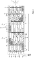
Figure 1 is a top view of a first embodiment of a thermal treatment machine comprising a plurality of modules in accordance with the present invention, with parts removed for clarity; -
Figure 2 is a top view in an enlarged scale of some components of the thermal treatment machine ofFigure 1 ; -
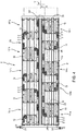
Figure 3 is a perspective view of a second embodiment of the thermal treatment machine ofFigure 1 ; -
Figure 4 is a top view of the second embodiment of the thermal treatment machine ofFigure 3 ; -
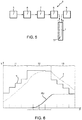
Figure 5 is a schematic representation of a bottling unit, which comprises the thermal treatment machine ofFigures 1 to 4 ; and -
Figure 6 is a plot of quantities related to a pasteurising process. - With reference to
Figures 1 and2 ,numeral 1 indicates as a whole a thermal treatment machine, in particular a tunnel pasteurizing machine for carrying out a thermal treatment, a pasteurization in the embodiment shown, on the edible product contained inside a plurality ofarticles 2. -
Tunnel pasteurizing machine 1 is adapted to be incorporated in a bottling line 4 (shown only schematically inFigure 5 ) for producing a plurality of filled, capped and labelledarticles 2. - In greater detail,
bottling line 4 substantially comprises: - a blowing
unit 5 for blowingarticles 2, starting from respective pre-forms; - a
rinsing unit 6 for rising thearticles 2; - a
filling unit 7 for filling thearticles 2 with the pourable edible product; - a
capping unit 8 for applying a plurality of caps ontorespective article 2; and - a
labelling unit 9 for labelling thearticles 2 with respective labels. - Preferably,
tunnel pasteurizing machine 1 is interposed betweencapping unit 8 and labellingunit 9, proceeding according the advancing direction ofarticles 2 insidebottling line 4. - Pasteurizing
machine 1 substantially comprises: - a conveying
group 10 for advancingarticles 2 from an input station I to an output station 0 along a path P; and - a plurality of
thermal zones Figure 6 ), which are adapted to carry out the thermal treatment on the edible product contained inarticles 2 travelling along path P. - In the embodiment shown, input and output stations I, 0 are arranged on respective opposite sides of pasteurizing
machine 1. - In particular, pasteurizing
machine 1 has a main extension parallel to a direction X. - In particular, pasteurizing
machine 1 comprises an infeedconveyor 26 for feeding input station I witharticles 2 to be treated an out-feed conveyor 27 arranged downstream of output station 0 and for outputting treatedarticles 2. -
Thermal zones heating zone 11, aheat treatment zone 12 and acooling zone 13 positioned one after another along path P, in order to carry out the pasteurisation of the edible product contained inarticles 2 3. - With reference to
Figure 2 , each one of the above sub-zones is provided with a respective spraying or injectingelement 14 for spraying or injecting a processing fluid (for example water) ontoarticles 2 advancing along path P in the same sub-zone, and with a respective not-shown collecting element, e.g. a tank, for collecting the processing fluid after it has been sprayed on the articles 2 (i.e. after it has exchanged heat with the same articles 2). In the shown embodiment, sprayingelement 14 and the collecting element are positioned above and, respectively, below path P defined by conveyinggroup 10, so as to exploit the gravity effect for the movement of the fluid. - Furthermore, pasteurizing
machine 1 comprises a fluid system (not shown in the Figures), which is controlled to implement recirculation of the processing fluid, so that the processing fluid fed to sprayingelements 14 of the sub-zones ofheating zone 11 is taken from the collecting elements of the sub-zones ofcooling zone 13, and the processing fluid fed to sprayingelements 14 of the sub-zones ofcooling zone 13 is taken from the collecting elements the sub-zones ofheating zone 11, in order to achieve a energy saving. - Accordingly, the edible product inside
articles 2 is at first heated, then pasteurized and finally cooled, asarticles 2 advance along path P. - Still more precisely, the temperature of the edible product follows a temperature profile as
articles 2 advance along path P. - With reference to
Figure 6 a graph is shown, with time on the x-axis and both temperatures and pasteurisation units on the y-axis, relating to a pasteurisation treatment in pasteurizingmachine 1 discussed above. - The graph refers to a system operational condition in which
articles 2 are fed at a constant speed along path P. - The graph shows: the product theoretical heating thermal trend (dotted curve t); the temperature of the processing liquid injected on the products (continuous curve T); and the accumulation trend of product pasteurisation units (bold continuous curve PU).
- Since the speed of conveying
group 10 is assumed to be constant, the graph may also be interpreted as a "photograph" of the condition of the edible product at each given moment. In this case, the x-axis shows the position of eacharticle 2 along path P, whilst the y-axis shows the values of the temperature t of the edible product insidearticle 2, the temperature T of the processing liquid and the quantity of pasteurisation units PU accumulated for the edible product of eacharticle 2 at that specific position. - Accordingly,
Figure 6 also showsheating zone 11,heat treatment zone 12 andcooling zone 13. By way of example, eachzone articles 2 along path P being from left to right, as shown by the arrow. It is therefore evident fromFigure 6 , that the edible product contained inarticles 2 accumulate substantially the whole amount of pasteurization units inheat treatment zone 12. - Furthermore, pasteurizing
machine 1 comprises a plurality ofmodules - Advantageously, the length of path P is selectively adjustable, so as to achieve a desired temperature profile of edible product inside
articles 2. - In greater detail, conveying
means 10 comprises, for eachmodule conveyors Figure 1 ) having respective conveyingsurfaces Figure 2 ) travelling in direction X along a first oriented direction and a plurality ofconveyors surfaces surfaces articles 2. - In the present description, the expression "oriented direction" indicates a direction oriented from a first side to a second side, e.g. from left side to right side or vice-versa.
- Each
module articles 2 travelling along conveyingsurface articles 2 from conveyingsurface surfaces - As will be evident from the foregoing, the length of path P is adjusted by adjusting the position of deviating means 20 with respect to conveying
surfaces - In particular, each
module - The inlet of
module 15a is fed witharticles 2 to be treated by inlet station I. - The outlet of each
module module articles 2. - The outlet of
module 15n feeds outlet 0 of pasteurizingmachine 1 with treatedarticles 2. - Each
module relative spraying element 14. - Conveying
surfaces - Direction Y is orthogonal to direction X and defines a horizontal plane with direction X. Conveying
surfaces - In particular, with reference to
modules Figure 2 ), conveyingsurface 19a is immediately consecutive to conveyingsurface 17a; conveyingsurfaces 17b is immediately consecutive to conveyingsurface 19a; conveyingsurface 19b is immediately consecutive to conveyingsurface 17b, etc., proceeding according to the advancing trajectory ofarticles 2 along path P. - Differently, with reference to
modules 15b, 15d, .., 15n, conveyingsurface 19c is immediately consecutive to conveyingsurface 17d; conveyingsurface 17c is immediately consecutive to conveyingsurface 19c; conveyingsurface 19b is immediately consecutive to surface 17c; conveyingsurface 17b is immediately consecutive to surface 19b; conveyingsurface 19a is immediately consecutive to surface 17b; and conveyingsurface 17a is immediately consecutive to surface 19a, proceeding according to the advancing trajectory ofarticles 2 along path P. - In the embodiment shown, the first oriented direction is oriented from inlet station I to outlet station 0 and the oriented direction is oriented from outlet station 0 to inlet station I.
- In the embodiment shown, the length of
conveyors modules - Furthermore, conveying
surface 17a and conveyingsurface 17d define respectively the inlet and the outlet ofmodule surface 17d and conveyingsurface 17a define respectively the inlet and the outlet ofmodules 15b, 15d, .., etc.. - In the embodiment shown,
conveyors modules - Deviating means 20 comprise, in turn,:
- a plurality of
deviators surface modules - a plurality of
deviators surfaces modules 15b, 15d, 15g, .., etc. - In particular,
deviator 21a deviate along direction Y orthogonal todirection X articles 2 from conveyingsurface 17a to conveyingsurface 19a. - Similarly,
deviator 21b deviate along direction Yarticles 2 from conveyingsurface 19a to conveying surface 17b., etc.. -
Deviators relative module - In greater detail,
deviators relative module -
Deviators relative module - Deviator 31a deviate
articles 2 along direction Y orthogonal todirection X articles 2 from conveyingsurface 17d to conveyingsurface 19c. - Similarly,
deviator 31b deviate along direction Yarticles 2 from conveyingsurface 19c to conveyingsurface 17c. -
Deviators relative module 15b, 15d.., etc and on the opposite side thereof. - In greater detail,
deviators relative module 15b, 15d, .., 15n. -
Deviators relative module 15b, 15d, .., 15n. - In the embodiment shown,
deviators Figure 2 ): -
straight guide surfaces surfaces surface -
curved guide surfaces surfaces relative guide surfaces surface - In a completely analogous way,
deviators - straight guide surfaces 23b, 23d, .., 23n (33b, 33d, ..) arranged on the side of conveying
surfaces surface 17c, 17f, .. (17c, 17b, ..); and - curved guide surfaces 22b, 22d, .. 22n (34b, 34d, 34f), which are arranged on the side of respective conveying
surfaces surface - Preferably, deviating means 20 also comprise, for each
module element 24 to whichdeviators module 15b, 15d, .. 15n a respective connectingelement 24 to whichdeviators - Preferably, deviating means 20 also comprise, for each
module element 25 to whichdeviators module 15b, 15d, .. 15n a respective connectingelement 25 to whichdeviators - In the embodiment shown, connecting
elements - Furthermore, connecting
elements - In one embodiment, connecting
elements - In another embodiment, the position of connecting
elements - In greater detail,
tunnel pasteurizing machine 1 comprises a control unit 30 (only schematically shown inFigure 1 ) receiving a signal associated to the desired temperature profile and is programmed to generate, on the basis of this signal, a control signal for displacingelements - Furthermore,
control unit 30 is programmed for selectively activating or de-activatingspraying elements 14. - In
case spraying elements 14 are deactivated, conveyinggroup 10 define a storage surface forarticles 2. The area of this storage surface can be selectively adjusted by suitably positioning deviating means 20 along direction X. - In use,
articles 2 travel along path P from input station I to output station 0. - As they travel along path P,
articles 2 travel along portions Q insiderelative modules machine 1. - In greater detail,
articles 2 move inside eachmodule 15a from relative inlet to relative outlet and on consecutive conveyingsurfaces articles 2 from each conveyingsurface surface - The temperature of the edible product inside
articles 2 varies along path P according to the temperature profile, as shown inFigure 6 . -
Control unit 30 adjusts the position of connectingelements deviators articles 2. In this way, the length of path P is adjusted to achieve the desired temperature profile. - If necessary,
control unit 30 can also deactivate sprayingelements 14, so as to define the storage surface forarticles 2 insidetunnel pasteurizing machine 1. -
Control unit 30 also defines the area of the storage surface by controlling the position of connectingelements - Still more precisely,
articles 2 travel along direction X and in the first oriented direction along conveyingsurface 17a, are deviated bydeviator 21a towards conveyingsurface 19a, travel along direction X and in the second oriented direction along conveyingsurface 19a, are deviated bydeviator 21b towards conveyingsurface 17b, etc.. - Afterwards,
articles 2 move insidemodules 15b, .., 15n from relative inlet to relative outlet. - In particular, as they move inside
module 15b, 15d, etc,articles 2 move on consecutive conveyingsurfaces articles 2 from each conveyingsurface surface - As they move inside
modules 15c, 15e, ..,articles 2 move on consecutive conveyingsurfaces articles 2 from each conveyingsurface surface - As
articles 2 advance along path P insidemodules thermal zones elements 14 spray the processing fluid ontoarticles 2, thus heating, pasteurizing and cooling the edible product insidearticles 2. - With reference to
Figures 3 and4 , 1' indicates, as a whole, a tunnel pasteurizing machine according to a second embodiment of the present invention. - Pasteurizing machine 1' is similar to pasteurizing
machine 1 and will be described hereinafter only as far as it differs therefrom; corresponding or equivalent parts of pasteurizingmachine 1, 1' will be indicated where possible by the same reference numbers. - In particular, pasteurizing machine 1' differs from pasteurizing
machine 1 in that inlet I and outlet 0 are arranged on the same side of it. - Furthermore, pasteurizing machine 1' comprises:
- a first group of modules 15'a, 15'b, .. 15'n aligned along direction X and in the first oriented direction, as to inlet I;
- a second group of
modules 15" a, 15"b, .., 15" n aligned along direction X and in the second oriented direction, up to outlet 0; and - a conveyor 50' which is interposed between the most downstram module 15'n of the first group and the most
upstream module 15"a of the second group, proceeding according to the advancing direction ofarticles 2 along path P. - In the embodiment shown, conveyor 50' is U-shaped.
- In particular, the first oriented direction is oriented from inlet I to conveyor 50' parallel to direction X.
- The second oriented direction is oriented from conveyor 50' to outlet 0 parallel to direction X.
- The operation of pasteurizing machine 1' is similar to the one of pasteurizing
machine 1 and is therefore not described in detail. - The advantages of
module - In particular, the length of path P is selectively adjustable independently of the length of pasteurizing
machine 1, 1' along direction X. - It is therefore possible to adjust the temperature profile without acting on the speed of conveying
group 10 and on the temperature of the fluid sprayed by sprayingmeans 8. - In particular,
modules articles 2 from conveyingsurface relative modules - Being each
module articles 2 to pass through a single sub-zone to time interval during whicharticles 2 pass through the remaining sub-zones. - Accordingly, it is possible to adjust the portion of the temperature profile associated to a single sub-zone without altering the remaining portions associated to corresponding remaining sub-zones.
- In the light of the module, the resulting pasteurizing
machine 1, 1' is particularly flexible in comparison with the known solution described in the introductory part of the present description. - Furthermore, the time interval during which
articles 2 pass through pasteurizingmachine 1, 1' can be easily adjusted by adjusting the position of deviating means 20 ofmodule - Accordingly, on one hand, it is possible to adjust the position of deviating means 20 on the basis of the desired temperature profile, thus rendering pasteurizing
machine 1, 1' suitable to process different edible products requiring different temperature profiles. - On the other hand, it is possible to match the throughput of pasteurizing
machine 1, 1' and fillingunit 7/capping unit 8 andlabelling unit 9. Accordingly, it is possible to advance a contained number of lines ofarticles 2 inside pasteurizing machine, thus avoiding any need for the inlet dividing station and the outlet dividing station. As a result, the final layout of pasteurizingmachine 1,l'and bottling unit 4 is strongly simplified, with evident advantages in terms of costs and easier maintenance. - Furthermore,
control unit 30 can adjust the position of deviating means 20 when sprayingelements 14 are deactivated. In this way, conveyingsurfaces - Finally, inlet I and outlet 0 are arranged at the same side of pasteurizing machine 1'.
- Accordingly, in comparison with pasteurizing
machine 1, 1', it is possible to concentrate thethermal zones 12, compact the final layout of the pasteurizing machine 1', and reduce the length of the equipment needed to recirculate back the processing fluid from the tank to sprayingelements 14. - In this way, a substantial simplification of the resulting pasteurizing machine 1' is achieved.
- Clearly, changes may be made to
module - In particular,
module surface surface deviator - Furthermore, the position of deviating means 20 could be adjusted on the basis of a quantity associated to the temperature profile of the edible product inside
articles 2. - Conveying
surface - Finally, pasteurizing
machine 1, 1' could be a cooling or warming machine.
Claims (17)
- A module (15a, 15b, .., 15n; 15a', 15b', .., 15n'; 15a", 15b", .., 15n") for a thermal treatment zone (11, 12, 13) of a thermal treatment machine (1, 1'), comprising:- conveying means (10) for advancing along a thermal treatment path (P) a plurality of articles (2) to be treated; and- thermal treatment means (14) selectively actuatable for carrying out a thermal treatment on said articles (2) advancing, in use, along said thermal treatment path (P);characterized in that the length of said thermal treatment path (P) is selectively adjustable, so as to achieve a desired temperature profile of the edible product contained in said articles (2).
- The module of claim 1, characterized in that said conveying means (10) comprise, in turn,:- a first conveyor (16a, 16b, .., 16n) having a first conveying surface (17a, 17b, .., 17n) movable at a first speed; and- a second conveyor (18a, 18b, .. 18n) having a second conveying surface (19a, 19b, .. 19n) movable at a second speed different from said first speed;said second conveying surface (19a, 19b, .., 19n) being immediately consecutive to said first conveying surface (17a, 17b, .., 17n), proceeding along said thermal treatment path (P) according to the advancing trajectory of said articles (2);
said module (15a, 15b, .., 15n; 15a', 15b', .., 15n'; 15a", 15b", .., 15n") further comprising deviating means (20) configured to interact, in use, with said articles (2) travelling along said first conveying surface (17a, 17b, .., 17n) and for deviating said articles (2) from said first conveying surface (17a, 17b, .., 17n) towards said second conveying surface (19a, 19b, .., 19n);
the position of said deviating means (20) with respect to said first and/or second conveying surface (17a, 17b, .., 17n; 19a, 19b, .., 19n) being adjustable, so as to adjust a length of said thermal treatment path (P). - The module of claim 2, characterized in that said first conveyor (16a, 16b, .., 16n) is movable along a first direction (X) and in a first oriented direction, and in that said second conveyor (18a, 18b, .. 18n) is movable along said first direction (X) and in second oriented direction, opposite to the first oriented direction.
- The module of claim 2 or 3, characterized in that said deviating means (20) comprise at least one deviator (21a, 21b, .. 21n; 31a, 31b, .., 31n) arranged at least in part along one of said first conveying surface (17a, 17b, .., 17n) and said second conveying surface (19a, 19b, .., 19n), and extending at least in part transversally to said one of first conveying surface (17a, 17b, .., 17n) and second conveying surface (19a, 19b, .., 19n).
- The module of claim 4, characterized by comprising a control unit (30) which is programmed to adjust said position of said deviating means (20), on the basis of a quantity associated to said desired temperature profile of the edible product contained in said articles (2).
- The module of claim 5, characterized in that said control unit (30) is programmed to selectively activate/deactivate said thermal treatment means (14), so as to form a given volume of storage inside said module (15a, 15b, .., 15n; 15a', 15b', .., 15n'; 15a", 15b", .., 15n") .
- The module of any one of the foregoing claims, characterized in that said conveying means (10) comprise a plurality of said first conveyors (16a, 16b, .., 16n) and second conveyors (18a, 18b, .., 18n) alternate to one another along a second direction (Y) transversal to said first direction (X).
- The module of claim 7, characterized in that said deviating means (20) comprises a plurality of deviators (21a, 21b, .. 21n; 31a, 31b, .., 31n) arranged, each, in part along said first conveying surface (17a, 17b, .., 17n) and extending transversally to said first and second conveying surfaces (17a, 17b, .., 17n; 19a, 19b, .., 19n).
- The module of any one of the foregoing claims, characterized in that said thermal treatment means (14) are cooling means or warming means.
- A thermal treatment machine (1, 1') comprising:- an inlet (I) for said articles (0) to be treated;- a plurality of thermal treatment modules (15a, 15b, .., 15n; 15a', 15b', .., 15n'; 15a", 15b", .., 15n") according to any one of the foregoing claims and arranged downstream of said inlet (I) proceeding along said path (P) according to the advancing direction of said articles (2); and- an outlet (0) for outputting said treated articles and arranged downstream of said modules ((15a, 15b, .., 15n; 15a', 15b', .., 15n'; 15a", 15b", .., 15n"), proceeding along said path (P) according to the advancing direction of said articles (2).
- The thermal treatment machine of claim 10, characterized in that said inlet and outlet (I, 0) are arranged at the same side of said thermal treatment machine (1, 1').
- The thermal treatment machine of claim 10, characterized in that said inlet and said outlet (I, 0) are arranged at respective opposite sides of said thermal treatment machine (1, 1').
- The thermal treatment machine of any one of claims 10 to 12, characterized by comprising a single first conveyor (16a, 16b, .., 16n) and a single said conveyor (18a, 18b, 18n) common to all said thermal treatment modules (15a, 15b, .., 15n; 15a', 15b', .., 15n'; 15a", 15b", .., 15n").
- A method for carrying out a thermal treatment on a plurality of articles (2), comprising the steps of:i) conveying a plurality of articles (2) to be treated along a thermal treatment path (P);ii) selectively carrying out a thermal treatment on said articles (2) travelling on said thermal treatment path (P) ;characterized in that said step i) comprises the steps of:iii) adjusting the length of said thermal treatment path (P) on the basis of a desired value of said length, so as to achieve a desired temperature profile of the edible product contained in said articles (2) during said step ii) .
- The method of claim 14, characterized by comprising the steps of:iv) conveying said articles (2) at a first speed on a first surface (17a, 17b,.., 17n); andv) conveying said articles (2) at a second speed different from said first speed on a second conveying surface (19a, 19b, .., 19n); said second conveying surface (19a, 19b, .., 19n) being immediately consecutive to said first conveying surface (17a, 17b,.., 17n), proceeding along said thermal treatment path (P) according to the advancing trajectory of said articles (2);said method further comprising a step vi) of deviating said articles (2) from said first surface (17a, 17b,.., 17n), towards said immediately adjacent second surface (19a, 19b, .., 19n).
- The method of claim 15, characterized in that said step vi) is carried out by means of deviating means (20) ;
said method further comprising a step vi) of adjusting the position of said deviating means (20) on the basis said desired temperature profile of the edible product inside said articles (2) to be achieved during said step ii). - The method of claim 15 or 16, characterized by comprising the steps of:vii) of moving said first surface (17a, 17b, .. 17n) along a first direction (X) and in a first oriented direction; andviii) moving said second surface (19a, 19b, .. 19n) is along said first direction (X) and in a second oriented direction, opposite to the first oriented direction.
Priority Applications (1)
| Application Number | Priority Date | Filing Date | Title |
|---|---|---|---|
| EP17197123.7A EP3473109A1 (en) | 2017-10-18 | 2017-10-18 | A module for a thermal treatment zone of a thermal treatment machine, and a method for carrying out a thermal treatment on a plurality of articles |
Applications Claiming Priority (1)
| Application Number | Priority Date | Filing Date | Title |
|---|---|---|---|
| EP17197123.7A EP3473109A1 (en) | 2017-10-18 | 2017-10-18 | A module for a thermal treatment zone of a thermal treatment machine, and a method for carrying out a thermal treatment on a plurality of articles |
Publications (1)
| Publication Number | Publication Date |
|---|---|
| EP3473109A1 true EP3473109A1 (en) | 2019-04-24 |
Family
ID=60143553
Family Applications (1)
| Application Number | Title | Priority Date | Filing Date |
|---|---|---|---|
| EP17197123.7A Withdrawn EP3473109A1 (en) | 2017-10-18 | 2017-10-18 | A module for a thermal treatment zone of a thermal treatment machine, and a method for carrying out a thermal treatment on a plurality of articles |
Country Status (1)
| Country | Link |
|---|---|
| EP (1) | EP3473109A1 (en) |
Cited By (1)
| Publication number | Priority date | Publication date | Assignee | Title |
|---|---|---|---|---|
| IT202200005936A1 (en) * | 2022-03-25 | 2023-09-25 | Sidel Participations Sas | Double flow counter-current pasteurizer with conditioning control |
Citations (7)
| Publication number | Priority date | Publication date | Assignee | Title |
|---|---|---|---|---|
| DE1492607A1 (en) * | 1964-03-19 | 1969-06-19 | Enzinger Union Werke Ag | Continuous pasteurizer for bottles and the like. |
| US6006536A (en) * | 1998-05-06 | 1999-12-28 | York International Corporation | System for multi-pass thermal treating of food products |
| EP1525808A1 (en) * | 2003-10-21 | 2005-04-27 | SIG Technology Ltd. | Tunnel pasteuriser |
| US20050126656A1 (en) * | 2003-11-10 | 2005-06-16 | Ulrich Wiedemann | Beverage bottling plant for filling bottles with a liquid beverage filling material having a treatment section |
| EP2058386A1 (en) | 2007-11-08 | 2009-05-13 | Sidel Holdings & Technology S.A. | Tunnel pasteuriser |
| EP2721935A1 (en) * | 2012-10-18 | 2014-04-23 | Sidel S.p.A. Con Socio Unico | System for controlling a machine for temperature processing of food products containers, and related machine |
| EP3015180A1 (en) * | 2014-10-29 | 2016-05-04 | Gebo Packaging Solutions Italy SRL | Washing unit for empty containers and corresponding method |
-
2017
- 2017-10-18 EP EP17197123.7A patent/EP3473109A1/en not_active Withdrawn
Patent Citations (9)
| Publication number | Priority date | Publication date | Assignee | Title |
|---|---|---|---|---|
| DE1492607A1 (en) * | 1964-03-19 | 1969-06-19 | Enzinger Union Werke Ag | Continuous pasteurizer for bottles and the like. |
| US6006536A (en) * | 1998-05-06 | 1999-12-28 | York International Corporation | System for multi-pass thermal treating of food products |
| EP1525808A1 (en) * | 2003-10-21 | 2005-04-27 | SIG Technology Ltd. | Tunnel pasteuriser |
| US20050126656A1 (en) * | 2003-11-10 | 2005-06-16 | Ulrich Wiedemann | Beverage bottling plant for filling bottles with a liquid beverage filling material having a treatment section |
| US7600542B2 (en) | 2003-11-10 | 2009-10-13 | Khs Maschinen- Und Anlagenbau Ag | Beverage bottling plant for filling bottles with a liquid beverage filling material having a treatment section |
| EP2058386A1 (en) | 2007-11-08 | 2009-05-13 | Sidel Holdings & Technology S.A. | Tunnel pasteuriser |
| US20090288565A1 (en) * | 2007-11-08 | 2009-11-26 | Sidel Holdings & Technology Sa | Tunnel pasteuriser |
| EP2721935A1 (en) * | 2012-10-18 | 2014-04-23 | Sidel S.p.A. Con Socio Unico | System for controlling a machine for temperature processing of food products containers, and related machine |
| EP3015180A1 (en) * | 2014-10-29 | 2016-05-04 | Gebo Packaging Solutions Italy SRL | Washing unit for empty containers and corresponding method |
Non-Patent Citations (1)
| Title |
|---|
| DILAY E ET AL: "Modeling, simulation and optimization of a beer pasteurization tunnel", JOURNAL OF FOOD ENGINEERING, BARKING, ESSEX, GB, vol. 77, no. 3, 1 December 2006 (2006-12-01), pages 500 - 513, XP027890779, ISSN: 0260-8774, [retrieved on 20061201] * |
Cited By (3)
| Publication number | Priority date | Publication date | Assignee | Title |
|---|---|---|---|---|
| IT202200005936A1 (en) * | 2022-03-25 | 2023-09-25 | Sidel Participations Sas | Double flow counter-current pasteurizer with conditioning control |
| WO2023180441A1 (en) * | 2022-03-25 | 2023-09-28 | Sidel Participations S.A.S. | "counter-current double-flow pasteurizer with conditioning control" |
| US12421094B2 (en) | 2022-03-25 | 2025-09-23 | Sidel Participations S.A.S | Counter-current double-flow pasteurizer with conditioning control |
Similar Documents
| Publication | Publication Date | Title |
|---|---|---|
| US4704958A (en) | Pasteurization apparatus | |
| EP2246161B1 (en) | Apparatus and method for cutting slices from a food product and load them onto a conveying surface, and treatment plant including said apparatus | |
| US3972679A (en) | Method for sterilizing and pasteurizing container packed products | |
| EP1790572B1 (en) | Packaging material sterilizing unit for a pourable food product packaging machine | |
| DK2691324T3 (en) | Storage Facilities | |
| EP3106397B1 (en) | Package grouping unit with package linear speed reduction | |
| EP3473109A1 (en) | A module for a thermal treatment zone of a thermal treatment machine, and a method for carrying out a thermal treatment on a plurality of articles | |
| CA1258401A (en) | Apparatus for continuously cooking and/or dehydrating foodstuffs | |
| CN101428694A (en) | Tunnel pasteuriser | |
| RU2004132542A (en) | METHOD OF OPERATION OF INSTALLATION FOR PASTERIZATION OF PRODUCTS IN TANKS | |
| CA2078332A1 (en) | Process and arrangement for obtaining constant product quality and safety in pasteurization plants in the event of a stoppage | |
| CN105053750B (en) | A kind of two sections of steaming plants of fish ball | |
| US5551334A (en) | Pasteurizer | |
| CN1615758A (en) | Pasteurization equipment | |
| EP3504984A1 (en) | A thermal treatment machine and a related method | |
| US20070082100A1 (en) | Bottle pasteurizer and method | |
| EP3505456A1 (en) | A thermal treatment machine and a related method | |
| CN104244742B (en) | Pasteurizing plant | |
| EP1525808A1 (en) | Tunnel pasteuriser | |
| EP3148903B1 (en) | Distribution system for supplying irregularly shaped products such as pears to a singulating means, and transport system and method therefor | |
| US11871757B2 (en) | Assembly and method for processing poultry | |
| EP3495291A1 (en) | An accumulation table and a method for operating an accumulation table | |
| EP2742810A1 (en) | Sprinkling apparatus, particularly for container processing machines | |
| WO1996002626A1 (en) | Method and apparatus for the pasteurization of a continuous line of products | |
| WO1996002626A9 (en) | Method and apparatus for the pasteurization of a continuous line of products |
Legal Events
| Date | Code | Title | Description |
|---|---|---|---|
| PUAI | Public reference made under article 153(3) epc to a published international application that has entered the european phase |
Free format text: ORIGINAL CODE: 0009012 |
|
| STAA | Information on the status of an ep patent application or granted ep patent |
Free format text: STATUS: THE APPLICATION HAS BEEN PUBLISHED |
|
| AK | Designated contracting states |
Kind code of ref document: A1 Designated state(s): AL AT BE BG CH CY CZ DE DK EE ES FI FR GB GR HR HU IE IS IT LI LT LU LV MC MK MT NL NO PL PT RO RS SE SI SK SM TR |
|
| AX | Request for extension of the european patent |
Extension state: BA ME |
|
| STAA | Information on the status of an ep patent application or granted ep patent |
Free format text: STATUS: REQUEST FOR EXAMINATION WAS MADE |
|
| 17P | Request for examination filed |
Effective date: 20191023 |
|
| RBV | Designated contracting states (corrected) |
Designated state(s): AL AT BE BG CH CY CZ DE DK EE ES FI FR GB GR HR HU IE IS IT LI LT LU LV MC MK MT NL NO PL PT RO RS SE SI SK SM TR |
|
| RIC1 | Information provided on ipc code assigned before grant |
Ipc: A23L 3/04 20060101AFI20200929BHEP |
|
| GRAP | Despatch of communication of intention to grant a patent |
Free format text: ORIGINAL CODE: EPIDOSNIGR1 |
|
| STAA | Information on the status of an ep patent application or granted ep patent |
Free format text: STATUS: GRANT OF PATENT IS INTENDED |
|
| INTG | Intention to grant announced |
Effective date: 20201109 |
|
| STAA | Information on the status of an ep patent application or granted ep patent |
Free format text: STATUS: THE APPLICATION IS DEEMED TO BE WITHDRAWN |
|
| 18D | Application deemed to be withdrawn |
Effective date: 20210320 |