EP3473129A1 - Mehrschichtige folie mit gewebe und harz, reisetasche daraus und vorrichtung zur herstellung davon - Google Patents
Mehrschichtige folie mit gewebe und harz, reisetasche daraus und vorrichtung zur herstellung davon Download PDFInfo
- Publication number
- EP3473129A1 EP3473129A1 EP17813606.5A EP17813606A EP3473129A1 EP 3473129 A1 EP3473129 A1 EP 3473129A1 EP 17813606 A EP17813606 A EP 17813606A EP 3473129 A1 EP3473129 A1 EP 3473129A1
- Authority
- EP
- European Patent Office
- Prior art keywords
- fabric
- roller
- resin
- multilayer sheet
- case
- Prior art date
- Legal status (The legal status is an assumption and is not a legal conclusion. Google has not performed a legal analysis and makes no representation as to the accuracy of the status listed.)
- Withdrawn
Links
- 239000004744 fabric Substances 0.000 title claims abstract description 268
- 229920005989 resin Polymers 0.000 title claims abstract description 233
- 239000011347 resin Substances 0.000 title claims abstract description 233
- 238000004519 manufacturing process Methods 0.000 title claims abstract description 75
- 239000000835 fiber Substances 0.000 claims description 28
- 230000008878 coupling Effects 0.000 claims description 24
- 238000010168 coupling process Methods 0.000 claims description 24
- 238000005859 coupling reaction Methods 0.000 claims description 24
- 239000000463 material Substances 0.000 claims description 17
- 239000004743 Polypropylene Substances 0.000 claims description 12
- 230000000149 penetrating effect Effects 0.000 claims description 12
- 229920001155 polypropylene Polymers 0.000 claims description 12
- -1 polypropylene Polymers 0.000 claims description 11
- 238000000465 moulding Methods 0.000 claims description 8
- 239000004033 plastic Substances 0.000 claims description 7
- 229920003023 plastic Polymers 0.000 claims description 7
- 230000003247 decreasing effect Effects 0.000 abstract description 3
- 230000002093 peripheral effect Effects 0.000 description 10
- 238000000034 method Methods 0.000 description 6
- 230000008569 process Effects 0.000 description 5
- 239000004594 Masterbatch (MB) Substances 0.000 description 4
- 239000004417 polycarbonate Substances 0.000 description 4
- 229920000515 polycarbonate Polymers 0.000 description 4
- 239000004676 acrylonitrile butadiene styrene Substances 0.000 description 3
- 230000008901 benefit Effects 0.000 description 3
- 239000004745 nonwoven fabric Substances 0.000 description 3
- 229920005992 thermoplastic resin Polymers 0.000 description 3
- 230000002087 whitening effect Effects 0.000 description 3
- 238000005516 engineering process Methods 0.000 description 2
- 239000003623 enhancer Substances 0.000 description 2
- 238000001125 extrusion Methods 0.000 description 2
- 230000005484 gravity Effects 0.000 description 2
- 238000010438 heat treatment Methods 0.000 description 2
- 239000002245 particle Substances 0.000 description 2
- 229920002994 synthetic fiber Polymers 0.000 description 2
- 239000012209 synthetic fiber Substances 0.000 description 2
- 239000004677 Nylon Substances 0.000 description 1
- XECAHXYUAAWDEL-UHFFFAOYSA-N acrylonitrile butadiene styrene Chemical compound C=CC=C.C=CC#N.C=CC1=CC=CC=C1 XECAHXYUAAWDEL-UHFFFAOYSA-N 0.000 description 1
- 229920000122 acrylonitrile butadiene styrene Polymers 0.000 description 1
- MTAZNLWOLGHBHU-UHFFFAOYSA-N butadiene-styrene rubber Chemical compound C=CC=C.C=CC1=CC=CC=C1 MTAZNLWOLGHBHU-UHFFFAOYSA-N 0.000 description 1
- 238000004040 coloring Methods 0.000 description 1
- 230000007423 decrease Effects 0.000 description 1
- 230000002950 deficient Effects 0.000 description 1
- 230000000694 effects Effects 0.000 description 1
- 230000005489 elastic deformation Effects 0.000 description 1
- 230000004048 modification Effects 0.000 description 1
- 238000012986 modification Methods 0.000 description 1
- 238000010137 moulding (plastic) Methods 0.000 description 1
- 229920001778 nylon Polymers 0.000 description 1
- 229920000728 polyester Polymers 0.000 description 1
- 238000003825 pressing Methods 0.000 description 1
- 239000002994 raw material Substances 0.000 description 1
- 239000011342 resin composition Substances 0.000 description 1
- 239000000126 substance Substances 0.000 description 1
- 238000009941 weaving Methods 0.000 description 1
- 230000037303 wrinkles Effects 0.000 description 1
Images


Classifications
-
- B—PERFORMING OPERATIONS; TRANSPORTING
- B32—LAYERED PRODUCTS
- B32B—LAYERED PRODUCTS, i.e. PRODUCTS BUILT-UP OF STRATA OF FLAT OR NON-FLAT, e.g. CELLULAR OR HONEYCOMB, FORM
- B32B37/00—Methods or apparatus for laminating, e.g. by curing or by ultrasonic bonding
- B32B37/14—Methods or apparatus for laminating, e.g. by curing or by ultrasonic bonding characterised by the properties of the layers
- B32B37/15—Methods or apparatus for laminating, e.g. by curing or by ultrasonic bonding characterised by the properties of the layers with at least one layer being manufactured and immediately laminated before reaching its stable state, e.g. in which a layer is extruded and laminated while in semi-molten state
- B32B37/153—Methods or apparatus for laminating, e.g. by curing or by ultrasonic bonding characterised by the properties of the layers with at least one layer being manufactured and immediately laminated before reaching its stable state, e.g. in which a layer is extruded and laminated while in semi-molten state at least one layer is extruded and immediately laminated while in semi-molten state
-
- A—HUMAN NECESSITIES
- A45—HAND OR TRAVELLING ARTICLES
- A45C—PURSES; LUGGAGE; HAND CARRIED BAGS
- A45C5/00—Rigid or semi-rigid luggage
- A45C5/03—Suitcases
-
- A—HUMAN NECESSITIES
- A45—HAND OR TRAVELLING ARTICLES
- A45C—PURSES; LUGGAGE; HAND CARRIED BAGS
- A45C5/00—Rigid or semi-rigid luggage
- A45C5/04—Trunks; Travelling baskets
-
- A—HUMAN NECESSITIES
- A45—HAND OR TRAVELLING ARTICLES
- A45C—PURSES; LUGGAGE; HAND CARRIED BAGS
- A45C5/00—Rigid or semi-rigid luggage
- A45C5/14—Rigid or semi-rigid luggage with built-in rolling means
-
- B—PERFORMING OPERATIONS; TRANSPORTING
- B29—WORKING OF PLASTICS; WORKING OF SUBSTANCES IN A PLASTIC STATE IN GENERAL
- B29C—SHAPING OR JOINING OF PLASTICS; SHAPING OF MATERIAL IN A PLASTIC STATE, NOT OTHERWISE PROVIDED FOR; AFTER-TREATMENT OF THE SHAPED PRODUCTS, e.g. REPAIRING
- B29C48/00—Extrusion moulding, i.e. expressing the moulding material through a die or nozzle which imparts the desired form; Apparatus therefor
- B29C48/001—Combinations of extrusion moulding with other shaping operations
- B29C48/0021—Combinations of extrusion moulding with other shaping operations combined with joining, lining or laminating
-
- B—PERFORMING OPERATIONS; TRANSPORTING
- B29—WORKING OF PLASTICS; WORKING OF SUBSTANCES IN A PLASTIC STATE IN GENERAL
- B29C—SHAPING OR JOINING OF PLASTICS; SHAPING OF MATERIAL IN A PLASTIC STATE, NOT OTHERWISE PROVIDED FOR; AFTER-TREATMENT OF THE SHAPED PRODUCTS, e.g. REPAIRING
- B29C48/00—Extrusion moulding, i.e. expressing the moulding material through a die or nozzle which imparts the desired form; Apparatus therefor
- B29C48/03—Extrusion moulding, i.e. expressing the moulding material through a die or nozzle which imparts the desired form; Apparatus therefor characterised by the shape of the extruded material at extrusion
- B29C48/07—Flat, e.g. panels
- B29C48/08—Flat, e.g. panels flexible, e.g. films
-
- B—PERFORMING OPERATIONS; TRANSPORTING
- B29—WORKING OF PLASTICS; WORKING OF SUBSTANCES IN A PLASTIC STATE IN GENERAL
- B29C—SHAPING OR JOINING OF PLASTICS; SHAPING OF MATERIAL IN A PLASTIC STATE, NOT OTHERWISE PROVIDED FOR; AFTER-TREATMENT OF THE SHAPED PRODUCTS, e.g. REPAIRING
- B29C48/00—Extrusion moulding, i.e. expressing the moulding material through a die or nozzle which imparts the desired form; Apparatus therefor
- B29C48/15—Extrusion moulding, i.e. expressing the moulding material through a die or nozzle which imparts the desired form; Apparatus therefor incorporating preformed parts or layers, e.g. extrusion moulding around inserts
- B29C48/154—Coating solid articles, i.e. non-hollow articles
-
- B—PERFORMING OPERATIONS; TRANSPORTING
- B29—WORKING OF PLASTICS; WORKING OF SUBSTANCES IN A PLASTIC STATE IN GENERAL
- B29C—SHAPING OR JOINING OF PLASTICS; SHAPING OF MATERIAL IN A PLASTIC STATE, NOT OTHERWISE PROVIDED FOR; AFTER-TREATMENT OF THE SHAPED PRODUCTS, e.g. REPAIRING
- B29C48/00—Extrusion moulding, i.e. expressing the moulding material through a die or nozzle which imparts the desired form; Apparatus therefor
- B29C48/16—Articles comprising two or more components, e.g. co-extruded layers
- B29C48/18—Articles comprising two or more components, e.g. co-extruded layers the components being layers
- B29C48/21—Articles comprising two or more components, e.g. co-extruded layers the components being layers the layers being joined at their surfaces
-
- B—PERFORMING OPERATIONS; TRANSPORTING
- B29—WORKING OF PLASTICS; WORKING OF SUBSTANCES IN A PLASTIC STATE IN GENERAL
- B29C—SHAPING OR JOINING OF PLASTICS; SHAPING OF MATERIAL IN A PLASTIC STATE, NOT OTHERWISE PROVIDED FOR; AFTER-TREATMENT OF THE SHAPED PRODUCTS, e.g. REPAIRING
- B29C70/00—Shaping composites, i.e. plastics material comprising reinforcements, fillers or preformed parts, e.g. inserts
- B29C70/04—Shaping composites, i.e. plastics material comprising reinforcements, fillers or preformed parts, e.g. inserts comprising reinforcements only, e.g. self-reinforcing plastics
- B29C70/06—Fibrous reinforcements only
-
- B—PERFORMING OPERATIONS; TRANSPORTING
- B29—WORKING OF PLASTICS; WORKING OF SUBSTANCES IN A PLASTIC STATE IN GENERAL
- B29C—SHAPING OR JOINING OF PLASTICS; SHAPING OF MATERIAL IN A PLASTIC STATE, NOT OTHERWISE PROVIDED FOR; AFTER-TREATMENT OF THE SHAPED PRODUCTS, e.g. REPAIRING
- B29C70/00—Shaping composites, i.e. plastics material comprising reinforcements, fillers or preformed parts, e.g. inserts
- B29C70/04—Shaping composites, i.e. plastics material comprising reinforcements, fillers or preformed parts, e.g. inserts comprising reinforcements only, e.g. self-reinforcing plastics
- B29C70/28—Shaping operations therefor
- B29C70/30—Shaping by lay-up, i.e. applying fibres, tape or broadsheet on a mould, former or core; Shaping by spray-up, i.e. spraying of fibres on a mould, former or core
- B29C70/34—Shaping by lay-up, i.e. applying fibres, tape or broadsheet on a mould, former or core; Shaping by spray-up, i.e. spraying of fibres on a mould, former or core and shaping or impregnating by compression, i.e. combined with compressing after the lay-up operation
-
- B—PERFORMING OPERATIONS; TRANSPORTING
- B29—WORKING OF PLASTICS; WORKING OF SUBSTANCES IN A PLASTIC STATE IN GENERAL
- B29C—SHAPING OR JOINING OF PLASTICS; SHAPING OF MATERIAL IN A PLASTIC STATE, NOT OTHERWISE PROVIDED FOR; AFTER-TREATMENT OF THE SHAPED PRODUCTS, e.g. REPAIRING
- B29C70/00—Shaping composites, i.e. plastics material comprising reinforcements, fillers or preformed parts, e.g. inserts
- B29C70/04—Shaping composites, i.e. plastics material comprising reinforcements, fillers or preformed parts, e.g. inserts comprising reinforcements only, e.g. self-reinforcing plastics
- B29C70/28—Shaping operations therefor
- B29C70/40—Shaping or impregnating by compression not applied
- B29C70/50—Shaping or impregnating by compression not applied for producing articles of indefinite length, e.g. prepregs, sheet moulding compounds [SMC] or cross moulding compounds [XMC]
-
- B—PERFORMING OPERATIONS; TRANSPORTING
- B29—WORKING OF PLASTICS; WORKING OF SUBSTANCES IN A PLASTIC STATE IN GENERAL
- B29C—SHAPING OR JOINING OF PLASTICS; SHAPING OF MATERIAL IN A PLASTIC STATE, NOT OTHERWISE PROVIDED FOR; AFTER-TREATMENT OF THE SHAPED PRODUCTS, e.g. REPAIRING
- B29C70/00—Shaping composites, i.e. plastics material comprising reinforcements, fillers or preformed parts, e.g. inserts
- B29C70/04—Shaping composites, i.e. plastics material comprising reinforcements, fillers or preformed parts, e.g. inserts comprising reinforcements only, e.g. self-reinforcing plastics
- B29C70/28—Shaping operations therefor
- B29C70/54—Component parts, details or accessories; Auxiliary operations, e.g. feeding or storage of prepregs or SMC after impregnation or during ageing
-
- B—PERFORMING OPERATIONS; TRANSPORTING
- B29—WORKING OF PLASTICS; WORKING OF SUBSTANCES IN A PLASTIC STATE IN GENERAL
- B29C—SHAPING OR JOINING OF PLASTICS; SHAPING OF MATERIAL IN A PLASTIC STATE, NOT OTHERWISE PROVIDED FOR; AFTER-TREATMENT OF THE SHAPED PRODUCTS, e.g. REPAIRING
- B29C70/00—Shaping composites, i.e. plastics material comprising reinforcements, fillers or preformed parts, e.g. inserts
- B29C70/68—Shaping composites, i.e. plastics material comprising reinforcements, fillers or preformed parts, e.g. inserts by incorporating or moulding on preformed parts, e.g. inserts or layers, e.g. foam blocks
-
- B—PERFORMING OPERATIONS; TRANSPORTING
- B32—LAYERED PRODUCTS
- B32B—LAYERED PRODUCTS, i.e. PRODUCTS BUILT-UP OF STRATA OF FLAT OR NON-FLAT, e.g. CELLULAR OR HONEYCOMB, FORM
- B32B27/00—Layered products comprising a layer of synthetic resin
- B32B27/12—Layered products comprising a layer of synthetic resin next to a fibrous or filamentary layer
-
- B—PERFORMING OPERATIONS; TRANSPORTING
- B32—LAYERED PRODUCTS
- B32B—LAYERED PRODUCTS, i.e. PRODUCTS BUILT-UP OF STRATA OF FLAT OR NON-FLAT, e.g. CELLULAR OR HONEYCOMB, FORM
- B32B27/00—Layered products comprising a layer of synthetic resin
- B32B27/32—Layered products comprising a layer of synthetic resin comprising polyolefins
-
- B—PERFORMING OPERATIONS; TRANSPORTING
- B32—LAYERED PRODUCTS
- B32B—LAYERED PRODUCTS, i.e. PRODUCTS BUILT-UP OF STRATA OF FLAT OR NON-FLAT, e.g. CELLULAR OR HONEYCOMB, FORM
- B32B3/00—Layered products comprising a layer with external or internal discontinuities or unevennesses, or a layer of non-planar shape; Layered products comprising a layer having particular features of form
- B32B3/26—Layered products comprising a layer with external or internal discontinuities or unevennesses, or a layer of non-planar shape; Layered products comprising a layer having particular features of form characterised by a particular shape of the outline of the cross-section of a continuous layer; characterised by a layer with cavities or internal voids ; characterised by an apertured layer
- B32B3/266—Layered products comprising a layer with external or internal discontinuities or unevennesses, or a layer of non-planar shape; Layered products comprising a layer having particular features of form characterised by a particular shape of the outline of the cross-section of a continuous layer; characterised by a layer with cavities or internal voids ; characterised by an apertured layer characterised by an apertured layer, the apertures going through the whole thickness of the layer, e.g. expanded metal, perforated layer, slit layer regular cells B32B3/12
-
- B—PERFORMING OPERATIONS; TRANSPORTING
- B32—LAYERED PRODUCTS
- B32B—LAYERED PRODUCTS, i.e. PRODUCTS BUILT-UP OF STRATA OF FLAT OR NON-FLAT, e.g. CELLULAR OR HONEYCOMB, FORM
- B32B5/00—Layered products characterised by the non- homogeneity or physical structure, i.e. comprising a fibrous, filamentary, particulate or foam layer; Layered products characterised by having a layer differing constitutionally or physically in different parts
- B32B5/02—Layered products characterised by the non- homogeneity or physical structure, i.e. comprising a fibrous, filamentary, particulate or foam layer; Layered products characterised by having a layer differing constitutionally or physically in different parts characterised by structural features of a fibrous or filamentary layer
- B32B5/022—Non-woven fabric
-
- B—PERFORMING OPERATIONS; TRANSPORTING
- B32—LAYERED PRODUCTS
- B32B—LAYERED PRODUCTS, i.e. PRODUCTS BUILT-UP OF STRATA OF FLAT OR NON-FLAT, e.g. CELLULAR OR HONEYCOMB, FORM
- B32B5/00—Layered products characterised by the non- homogeneity or physical structure, i.e. comprising a fibrous, filamentary, particulate or foam layer; Layered products characterised by having a layer differing constitutionally or physically in different parts
- B32B5/02—Layered products characterised by the non- homogeneity or physical structure, i.e. comprising a fibrous, filamentary, particulate or foam layer; Layered products characterised by having a layer differing constitutionally or physically in different parts characterised by structural features of a fibrous or filamentary layer
- B32B5/024—Woven fabric
-
- B—PERFORMING OPERATIONS; TRANSPORTING
- B32—LAYERED PRODUCTS
- B32B—LAYERED PRODUCTS, i.e. PRODUCTS BUILT-UP OF STRATA OF FLAT OR NON-FLAT, e.g. CELLULAR OR HONEYCOMB, FORM
- B32B5/00—Layered products characterised by the non- homogeneity or physical structure, i.e. comprising a fibrous, filamentary, particulate or foam layer; Layered products characterised by having a layer differing constitutionally or physically in different parts
- B32B5/02—Layered products characterised by the non- homogeneity or physical structure, i.e. comprising a fibrous, filamentary, particulate or foam layer; Layered products characterised by having a layer differing constitutionally or physically in different parts characterised by structural features of a fibrous or filamentary layer
- B32B5/026—Knitted fabric
-
- B—PERFORMING OPERATIONS; TRANSPORTING
- B32—LAYERED PRODUCTS
- B32B—LAYERED PRODUCTS, i.e. PRODUCTS BUILT-UP OF STRATA OF FLAT OR NON-FLAT, e.g. CELLULAR OR HONEYCOMB, FORM
- B32B5/00—Layered products characterised by the non- homogeneity or physical structure, i.e. comprising a fibrous, filamentary, particulate or foam layer; Layered products characterised by having a layer differing constitutionally or physically in different parts
- B32B5/02—Layered products characterised by the non- homogeneity or physical structure, i.e. comprising a fibrous, filamentary, particulate or foam layer; Layered products characterised by having a layer differing constitutionally or physically in different parts characterised by structural features of a fibrous or filamentary layer
- B32B5/08—Layered products characterised by the non- homogeneity or physical structure, i.e. comprising a fibrous, filamentary, particulate or foam layer; Layered products characterised by having a layer differing constitutionally or physically in different parts characterised by structural features of a fibrous or filamentary layer the fibres or filaments of a layer being of different substances, e.g. conjugate fibres, mixture of different fibres
-
- A—HUMAN NECESSITIES
- A45—HAND OR TRAVELLING ARTICLES
- A45C—PURSES; LUGGAGE; HAND CARRIED BAGS
- A45C13/00—Details; Accessories
- A45C13/26—Special adaptations of handles
- A45C13/262—Special adaptations of handles for wheeled luggage
-
- A—HUMAN NECESSITIES
- A45—HAND OR TRAVELLING ARTICLES
- A45C—PURSES; LUGGAGE; HAND CARRIED BAGS
- A45C5/00—Rigid or semi-rigid luggage
- A45C5/03—Suitcases
- A45C2005/037—Suitcases with a hard shell, i.e. rigid shell as volume creating element
-
- A—HUMAN NECESSITIES
- A45—HAND OR TRAVELLING ARTICLES
- A45C—PURSES; LUGGAGE; HAND CARRIED BAGS
- A45C5/00—Rigid or semi-rigid luggage
- A45C5/02—Materials therefor
-
- A—HUMAN NECESSITIES
- A45—HAND OR TRAVELLING ARTICLES
- A45C—PURSES; LUGGAGE; HAND CARRIED BAGS
- A45C5/00—Rigid or semi-rigid luggage
- A45C5/04—Trunks; Travelling baskets
- A45C5/045—Travelling baskets
-
- B—PERFORMING OPERATIONS; TRANSPORTING
- B29—WORKING OF PLASTICS; WORKING OF SUBSTANCES IN A PLASTIC STATE IN GENERAL
- B29C—SHAPING OR JOINING OF PLASTICS; SHAPING OF MATERIAL IN A PLASTIC STATE, NOT OTHERWISE PROVIDED FOR; AFTER-TREATMENT OF THE SHAPED PRODUCTS, e.g. REPAIRING
- B29C48/00—Extrusion moulding, i.e. expressing the moulding material through a die or nozzle which imparts the desired form; Apparatus therefor
- B29C48/15—Extrusion moulding, i.e. expressing the moulding material through a die or nozzle which imparts the desired form; Apparatus therefor incorporating preformed parts or layers, e.g. extrusion moulding around inserts
-
- B—PERFORMING OPERATIONS; TRANSPORTING
- B29—WORKING OF PLASTICS; WORKING OF SUBSTANCES IN A PLASTIC STATE IN GENERAL
- B29C—SHAPING OR JOINING OF PLASTICS; SHAPING OF MATERIAL IN A PLASTIC STATE, NOT OTHERWISE PROVIDED FOR; AFTER-TREATMENT OF THE SHAPED PRODUCTS, e.g. REPAIRING
- B29C51/00—Shaping by thermoforming, i.e. shaping sheets or sheet like preforms after heating, e.g. shaping sheets in matched moulds or by deep-drawing; Apparatus therefor
- B29C51/14—Shaping by thermoforming, i.e. shaping sheets or sheet like preforms after heating, e.g. shaping sheets in matched moulds or by deep-drawing; Apparatus therefor using multilayered preforms or sheets
- B29C51/145—Shaping by thermoforming, i.e. shaping sheets or sheet like preforms after heating, e.g. shaping sheets in matched moulds or by deep-drawing; Apparatus therefor using multilayered preforms or sheets having at least one layer of textile or fibrous material combined with at least one plastics layer
-
- B—PERFORMING OPERATIONS; TRANSPORTING
- B29—WORKING OF PLASTICS; WORKING OF SUBSTANCES IN A PLASTIC STATE IN GENERAL
- B29C—SHAPING OR JOINING OF PLASTICS; SHAPING OF MATERIAL IN A PLASTIC STATE, NOT OTHERWISE PROVIDED FOR; AFTER-TREATMENT OF THE SHAPED PRODUCTS, e.g. REPAIRING
- B29C70/00—Shaping composites, i.e. plastics material comprising reinforcements, fillers or preformed parts, e.g. inserts
- B29C70/04—Shaping composites, i.e. plastics material comprising reinforcements, fillers or preformed parts, e.g. inserts comprising reinforcements only, e.g. self-reinforcing plastics
- B29C70/28—Shaping operations therefor
- B29C70/40—Shaping or impregnating by compression not applied
- B29C70/50—Shaping or impregnating by compression not applied for producing articles of indefinite length, e.g. prepregs, sheet moulding compounds [SMC] or cross moulding compounds [XMC]
- B29C70/504—Shaping or impregnating by compression not applied for producing articles of indefinite length, e.g. prepregs, sheet moulding compounds [SMC] or cross moulding compounds [XMC] using rollers or pressure bands
-
- B—PERFORMING OPERATIONS; TRANSPORTING
- B29—WORKING OF PLASTICS; WORKING OF SUBSTANCES IN A PLASTIC STATE IN GENERAL
- B29L—INDEXING SCHEME ASSOCIATED WITH SUBCLASS B29C, RELATING TO PARTICULAR ARTICLES
- B29L2031/00—Other particular articles
- B29L2031/712—Containers; Packaging elements or accessories, Packages
- B29L2031/7162—Boxes, cartons, cases
-
- B—PERFORMING OPERATIONS; TRANSPORTING
- B32—LAYERED PRODUCTS
- B32B—LAYERED PRODUCTS, i.e. PRODUCTS BUILT-UP OF STRATA OF FLAT OR NON-FLAT, e.g. CELLULAR OR HONEYCOMB, FORM
- B32B2250/00—Layers arrangement
- B32B2250/03—3 layers
-
- B—PERFORMING OPERATIONS; TRANSPORTING
- B32—LAYERED PRODUCTS
- B32B—LAYERED PRODUCTS, i.e. PRODUCTS BUILT-UP OF STRATA OF FLAT OR NON-FLAT, e.g. CELLULAR OR HONEYCOMB, FORM
- B32B2250/00—Layers arrangement
- B32B2250/05—5 or more layers
-
- B—PERFORMING OPERATIONS; TRANSPORTING
- B32—LAYERED PRODUCTS
- B32B—LAYERED PRODUCTS, i.e. PRODUCTS BUILT-UP OF STRATA OF FLAT OR NON-FLAT, e.g. CELLULAR OR HONEYCOMB, FORM
- B32B2250/00—Layers arrangement
- B32B2250/40—Symmetrical or sandwich layers, e.g. ABA, ABCBA, ABCCBA
-
- B—PERFORMING OPERATIONS; TRANSPORTING
- B32—LAYERED PRODUCTS
- B32B—LAYERED PRODUCTS, i.e. PRODUCTS BUILT-UP OF STRATA OF FLAT OR NON-FLAT, e.g. CELLULAR OR HONEYCOMB, FORM
- B32B2250/00—Layers arrangement
- B32B2250/42—Alternating layers, e.g. ABAB(C), AABBAABB(C)
-
- B—PERFORMING OPERATIONS; TRANSPORTING
- B32—LAYERED PRODUCTS
- B32B—LAYERED PRODUCTS, i.e. PRODUCTS BUILT-UP OF STRATA OF FLAT OR NON-FLAT, e.g. CELLULAR OR HONEYCOMB, FORM
- B32B2262/00—Composition or structural features of fibres which form a fibrous or filamentary layer or are present as additives
- B32B2262/02—Synthetic macromolecular fibres
- B32B2262/0253—Polyolefin fibres
-
- B—PERFORMING OPERATIONS; TRANSPORTING
- B32—LAYERED PRODUCTS
- B32B—LAYERED PRODUCTS, i.e. PRODUCTS BUILT-UP OF STRATA OF FLAT OR NON-FLAT, e.g. CELLULAR OR HONEYCOMB, FORM
- B32B2262/00—Composition or structural features of fibres which form a fibrous or filamentary layer or are present as additives
- B32B2262/14—Mixture of at least two fibres made of different materials
-
- B—PERFORMING OPERATIONS; TRANSPORTING
- B32—LAYERED PRODUCTS
- B32B—LAYERED PRODUCTS, i.e. PRODUCTS BUILT-UP OF STRATA OF FLAT OR NON-FLAT, e.g. CELLULAR OR HONEYCOMB, FORM
- B32B2305/00—Condition, form or state of the layers or laminate
- B32B2305/10—Fibres of continuous length
- B32B2305/18—Fabrics, textiles
-
- B—PERFORMING OPERATIONS; TRANSPORTING
- B32—LAYERED PRODUCTS
- B32B—LAYERED PRODUCTS, i.e. PRODUCTS BUILT-UP OF STRATA OF FLAT OR NON-FLAT, e.g. CELLULAR OR HONEYCOMB, FORM
- B32B2307/00—Properties of the layers or laminate
- B32B2307/40—Properties of the layers or laminate having particular optical properties
- B32B2307/412—Transparent
-
- B—PERFORMING OPERATIONS; TRANSPORTING
- B32—LAYERED PRODUCTS
- B32B—LAYERED PRODUCTS, i.e. PRODUCTS BUILT-UP OF STRATA OF FLAT OR NON-FLAT, e.g. CELLULAR OR HONEYCOMB, FORM
- B32B2307/00—Properties of the layers or laminate
- B32B2307/50—Properties of the layers or laminate having particular mechanical properties
- B32B2307/54—Yield strength; Tensile strength
-
- B—PERFORMING OPERATIONS; TRANSPORTING
- B32—LAYERED PRODUCTS
- B32B—LAYERED PRODUCTS, i.e. PRODUCTS BUILT-UP OF STRATA OF FLAT OR NON-FLAT, e.g. CELLULAR OR HONEYCOMB, FORM
- B32B2307/00—Properties of the layers or laminate
- B32B2307/50—Properties of the layers or laminate having particular mechanical properties
- B32B2307/558—Impact strength, toughness
-
- B—PERFORMING OPERATIONS; TRANSPORTING
- B32—LAYERED PRODUCTS
- B32B—LAYERED PRODUCTS, i.e. PRODUCTS BUILT-UP OF STRATA OF FLAT OR NON-FLAT, e.g. CELLULAR OR HONEYCOMB, FORM
- B32B2323/00—Polyalkenes
- B32B2323/10—Polypropylene
-
- B—PERFORMING OPERATIONS; TRANSPORTING
- B32—LAYERED PRODUCTS
- B32B—LAYERED PRODUCTS, i.e. PRODUCTS BUILT-UP OF STRATA OF FLAT OR NON-FLAT, e.g. CELLULAR OR HONEYCOMB, FORM
- B32B2439/00—Containers; Receptacles
- B32B2439/40—Closed containers
- B32B2439/46—Bags
-
- B—PERFORMING OPERATIONS; TRANSPORTING
- B32—LAYERED PRODUCTS
- B32B—LAYERED PRODUCTS, i.e. PRODUCTS BUILT-UP OF STRATA OF FLAT OR NON-FLAT, e.g. CELLULAR OR HONEYCOMB, FORM
- B32B2439/00—Containers; Receptacles
- B32B2439/40—Closed containers
- B32B2439/62—Boxes, cartons, cases
-
- B—PERFORMING OPERATIONS; TRANSPORTING
- B32—LAYERED PRODUCTS
- B32B—LAYERED PRODUCTS, i.e. PRODUCTS BUILT-UP OF STRATA OF FLAT OR NON-FLAT, e.g. CELLULAR OR HONEYCOMB, FORM
- B32B37/00—Methods or apparatus for laminating, e.g. by curing or by ultrasonic bonding
- B32B37/02—Methods or apparatus for laminating, e.g. by curing or by ultrasonic bonding characterised by a sequence of laminating steps, e.g. by adding new layers at consecutive laminating stations
-
- B—PERFORMING OPERATIONS; TRANSPORTING
- B32—LAYERED PRODUCTS
- B32B—LAYERED PRODUCTS, i.e. PRODUCTS BUILT-UP OF STRATA OF FLAT OR NON-FLAT, e.g. CELLULAR OR HONEYCOMB, FORM
- B32B5/00—Layered products characterised by the non- homogeneity or physical structure, i.e. comprising a fibrous, filamentary, particulate or foam layer; Layered products characterised by having a layer differing constitutionally or physically in different parts
- B32B5/22—Layered products characterised by the non- homogeneity or physical structure, i.e. comprising a fibrous, filamentary, particulate or foam layer; Layered products characterised by having a layer differing constitutionally or physically in different parts characterised by the presence of two or more layers which are next to each other and are fibrous, filamentary, formed of particles or foamed
- B32B5/24—Layered products characterised by the non- homogeneity or physical structure, i.e. comprising a fibrous, filamentary, particulate or foam layer; Layered products characterised by having a layer differing constitutionally or physically in different parts characterised by the presence of two or more layers which are next to each other and are fibrous, filamentary, formed of particles or foamed one layer being a fibrous or filamentary layer
- B32B5/26—Layered products characterised by the non- homogeneity or physical structure, i.e. comprising a fibrous, filamentary, particulate or foam layer; Layered products characterised by having a layer differing constitutionally or physically in different parts characterised by the presence of two or more layers which are next to each other and are fibrous, filamentary, formed of particles or foamed one layer being a fibrous or filamentary layer another layer next to it also being fibrous or filamentary
Definitions
- the present disclosure relates to a multilayer sheet, a case of a travel bag, and a method for manufacturing the same. More particularly, the present disclosure relates to a multilayer sheet constituting a raw material of a case of a travel bag in which articles are contained, a case configured by press-molding such a multilayer sheet, and a case manufacturing device.
- Travel bags are used to store and protect articles for travel. Commonly used travel bags have casters and handles installed thereon. Travel bags are largely classified into hard cases and soft cases according to the material of the bag body (case).
- Soft case travel bags have a drawback in that, if a wire is bent by an external impact, it is impossible to restore the same to the original condition.
- Hard cases are the most prevalent type of cases on the current market.
- the bag body (case) itself is made of hard plastic such that the same can maintain the shape without a skeleton structure such as a wire.
- the bag body is both hard and elastic, thereby having an excellent function of protecting objects contained therein.
- Korean Registered Patent No. 10-1189901 (Registration Date: October 4, 2012) discloses a feature wherein a polypropylene resin composition is used to manufacture a travel bag.
- a polypropylene resin composition is used to manufacture a travel bag.
- it is still requested to develop a travel bag having a new structure, in order to manufacture a hard case-type travel bag, the strength of which can be improved further.
- An aspect of the present disclosure is to provide a multilayer sheet, a case of a travel bag, and a case manufacturing device for manufacturing the same, wherein a fabric constituting the case of a travel bag and a plurality of layers made of thermoplastic resin, laminated on the fabric, are tightly laminated, thereby improving elasticity and durability, and the type of weaving of the fabric and the color impression thereof are naturally exposed to the outside while protecting the fabric.
- Another aspect of the present disclosure is to provide a multilayer sheet, a case of a travel bag, and a case manufacturing device for manufacturing the same, wherein, compared with conventional travel bags made of polycarbonate (PC), acrylonitrile butadiene styrene (BS), polypropylene (PP), and the like, the rigidity and durability can be improved while reducing the manufacturing cost and decreasing the weight.
- PC polycarbonate
- BS acrylonitrile butadiene styrene
- PP polypropylene
- a multilayer sheet constituting a case of a travel bag, the shape of which is made through plastic working such that articles are contained therein, the multilayer sheet having elastically restoring power and including: a first fabric that includes a fabric configured by coupling of fibers and has multiple through-holes penetrating the fabric; a first resin laminated on the first fabric and absorbed and coated on a surface of the first fabric; and a second resin laminated on the first fabric from a side opposite to the first resin, absorbed and coated on the surface of the first fabric, and coupled to the first resin via the through-holes.
- the multilayer sheet according to the present disclosure may include: a second fabric that includes a fabric configured by coupling of fibers and has multiple through-holes penetrating the fabric, the second fabric being laminated on the first resin from a side opposite to the first fabric; and a third fabric that includes a fabric configured by coupling of fibers and has multiple through-holes penetrating the fabric, the third fabric being laminated on the second resin from the side opposite to the first fabric.
- the first fabric may be made of a woven material
- the first fabric, the first resin, and the second resin may be made of polypropylene, and at least one of the first resin and the second resin may be configured to be transparent.
- the through-holes may have a width of 0.5-20mm.
- a case of a travel bag including the above-mentioned multilayer sheet configured by press working.
- a case manufacturing device for manufacturing a case of a travel bag, the shape of which is made through plastic working such that articles are contained therein, the travel bag having elastically restoring power
- the first roller may be configured to directly contact the first resin; the second roller may be configured to directly contact the first fabric; the third roller may be configured to directly contact the first resin laminated on the first fabric; the fourth roller is configured to directly contact the second resin; and the first roller, the second roller, the third roller, and the fourth roller may be continuously arranged in a row.
- the case manufacturing device may further include a fifth roller arranged adjacent to the fourth roller and configured to rotate in the opposite direction to the fourth roller.
- the surface temperature of the second roller may be higher than the surface temperature of the first roller.
- the surface temperature of the third roller and the fourth roller may be higher than the surface of the second roller.
- the surface temperature of the fifth roller may be higher than the surface temperature of the third roller and the fourth roller.
- the case manufacturing device may further include a second fabric supply portion configured to continuously supply a second fabric that includes a fabric configured by coupling of fibers and has multiple through-holes penetrating the fabric.
- the first roller and the second roller may be configured such that the second fabric, the first resin, and the first fabric pass between the first roller and the second roller and become laminated successively.
- the case manufacturing device may further include a third fabric supply portion configured to continuously supply a third fabric that includes a fabric configured by coupling of fibers and has multiple through-holes penetrating the fabric.
- Third roller and the fourth roller may be configured such that the second fabric, the first resin, the first fabric, the second resin, and the third fabric between the third roller and the fourth roller and become laminated successively.
- the case manufacturing device may include: a sheet clamp configured to hold an edge of a multilayer sheet including the first resin, the first fabric, and the second resin after passing through the third roller and the fourth roller; a preheater having multiple slots into which the sheet clamp is inserted, the preheater being configured such that a hot wind is supplied and circulated therein; and a molding machine configured to press-work the multilayer sheet preheated through the preheater.
- the slots may be arranged to be spaced apart from each other in a leftward/rightward direction.
- the multilayer sheet includes a first resin, a first fabric, and a second resin.
- the first resin, the first fabric, and the second resin are made of polypropylene.
- the first resin and/or the second resin are configured to be transparent. Accordingly, the first fabric, the first resin, and the second resin can be coupled tightly, and the compactness and strength of the multilayer sheet can be maximized.
- the unique color of the first fabric can be seen from the outside through the first resin and/or the second resin, making it unnecessary to mix or apply a master batch in a normal extrusion type such that a color is exhibited.
- the first fabric is positioned at the center of the multilayer sheet, and the first resin and the second resin are coated and positioned on both sides of the first fabric.
- This advantageously increases the tensile strength and impact strength of the entire multilayer sheet to a large extent.
- the first resin and/or the second resin are configured to be transparent, the aesthetic appearance unique to the first fabric (the texture type, pattern, and the like specific to the fabric resulting from interweaving of a warp and a weft) and the naturalness thereof can be directly seen from and embedded in the case. It is also possible to provide a travel bag with an excellent quality even if the manufacturing cost and manufacturing process are reduced.
- the first resin, the first fabric, and the second resin are all made of the same polypropylene such that, compared with conventional travel bags made of polycarbonate (PC), acrylonitrile butadiene styrene (ABS), and the like, the product price can be reduced substantially, there is no need to add a separate impact resistance enhancer in order to increase the impact strength and the tensile strength, and no master batch needs to be applied.
- PC polycarbonate
- ABS acrylonitrile butadiene styrene
- This provides a substantial advantage in terms of mass production and industrial applicability, and, since the weight can be reduced substantially, the user convenience and bag operability (mobility or the like) can be maximized.
- the multilayer sheet has a first fabric positioned between the first resin and the second resin, thereby constituting a multilayered structure. This substantially lowers the possibility that the multilayer sheet or the case will be torn by an external impact.
- the excellent elastically restoring power guarantees that, even if creased or recessed, the same can instantly return to the original condition. Furthermore, the possibility that whitening marks will be formed can be reduced substantially.
- a case manufacturing device capable of manufacturing a multilayer sheet and a case of a travel bag, which have very excellent compactness, tensile strength, and impact strength.
- FIG. 1 is a perspective view of a travel bag 1 according to the present disclosure.
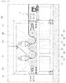
- FIG. 2 schematically illustrates a partial configuration of a case manufacturing device 100 according to the present disclosure.
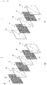
- FIG. 3 is an exploded perspective view schematically illustrating a multilayer sheet 3 according to the present disclosure.
- the multilayer sheet 3 is expressed in line type in FIG. 2 , the multilayer sheet 3 has a width in a direction parallel with the rotating shafts 311, 321, 331, 341, and 351 of respective rollers 310, 320, 330, 340, and 350.
- FIG. 3 is for the purpose of illustrating the laminated configuration of the multilayer sheet 3.
- the first fabric 10, the first resin 20, and the second resin 30 may have forms different from those illustrated in FIG. 3 , and may also have sizes larger than those illustrated in FIG. 3 .
- the case 2 of the travel bag 1 according to the present disclosure (hereinafter, simply referred to as the case 2) is shaped such that articles can be contained therein. As illustrated in FIG. 1 , a handle 4, casters 5, and the like may be coupled to the case 2, thereby configuring a travel bag 1 in a complete form.
- the case 2 may have various forms and sizes as long as articles can be contained therein.
- the case 2 may include two separate parts, the edges of which are coupled to each other by a zipper or the like.
- the two parts of the case 2, constituting a pair are separately manufactured and then assembled.
- a pre-molded multilayer sheet 3 is subjected to plastic working through plastic molding such that the form of the case 2 is made.
- the multilayer sheet 3 is configured in a flat plate type, and the case 2 is variously shaped to be curved or bent according to the mold for pressing molding.
- the multilayer sheet 3 refers to a multilayer sheet 3 that constitutes the case 2 of a travel bag in which articles are contained.
- the multilayer sheet 3 basically includes a first fabric 10, a first resin 20, and a second resin 30.
- the first fabric 10 is formed by coupling of fibers, and has multiple through-holes 13 that penetrate the fabric.
- the first fabric 10 is configured in a thin cloth type and has through-holes 13 that penetrate the same from one surface to the other surface thereof. Such through-holes 13 are repeatedly arranged throughout the entire area of the first fabric 10.
- the first fabric 10 may be made of a woven material, a knitted material, a non-woven fabric, or a combination thereof. Particularly, the first fabric 10 is preferably made of a woven material.
- a warp 11 (the warp 11 itself may be made of a combination of multiple fiber strands) and a weft 12 (the weft 12 itself may be made of a combination of multiple fiber strands) are woven to repeatedly intersect one above the other, as fibers that constitute the first fabric 10. Accordingly, the warp 11 and the weft 12 form a lattice shape, which is repeatedly penetrated by holes (through-holes 13).
- the width of the through-holes 13 (the length of one side of each through-hole when the first fabric 10 constitutes a lattice) may be 0.5-20mm. Particularly, the width is preferably 1-3mm.
- the first fabric 10 may be made of a natural fiber, a synthetic fiber, or a combination thereof, but is preferably made of a synthetic fiber. Particularly, the first fabric 10 is made of a polypropylene fiber.
- the first resin 20 is laminated on the first fiber 10 from one side surface of the first fabric 10, and is forced against and coupled to the first fabric 10.
- the first resin 20 may be made of a thermoplastic resin.
- the first resin 20 is preferably made of polypropylene.
- the first resin 20, made of the same material as that of the first fabric 10 as such, can be coupled to the first fabric 10 more tightly.
- the first fabric 10 is made of a combination of multiple fibers such that particles of the first resin 20 infiltrate between fiber strands that constitute the first fabric 10, thereby resulting in firm coupling between the two.
- the first resin 20 may be configured to be transparent.
- the second resin 30 is laminated on the first fiber 10 from the opposite side of the first resin 20, and is forced against and coupled to the first fabric 10.
- the first resin 20 and the second resin 30 are coupled to each other via the through-holes 13 of the first fabric 10.
- the second resin 30 may be made of a thermoplastic resin and, particularly, is preferably made of polypropylene.
- the first fabric 10 is made of a combination of multiple fibers such that particles of the second resin 30 infiltrate between fiber strands that constitute the first fabric 10, thereby resulting in firm coupling between the two.
- the second resin 30 contacts and is coupled to the first resin 20 via the through-holes of the first fabric 10 such that the first resin 20, the first fabric 10, and the second resin 30 are coupled in a very stable and robust manner.
- the second resin 30 may be configured to be transparent.
- the multilayer sheet 3 has the following advantages.
- the same includes a first resin 20, a first fabric 10, and a second resin 30.
- the first resin 20, the first fabric 10, and the second resin 30 are made of polypropylene.
- the first resin 20 and/or the second resin 30 are configured to be transparent. Accordingly, the first fabric 10, the first resin 20, and the second resin 30 can be coupled tightly, and the compactness and strength of the multilayer sheet 3 can be maximized.
- the unique color of the first fabric 10 appears through the first resin 20 and/or the second resin 30, making it unnecessary to mix or apply a master batch in a normal extrusion type such that a color is exhibited.
- the first fabric 10 is positioned at the center of the multilayer sheet 3, and the first resin 20 and the second resin 30 are coated and positioned on both sides of the first fabric 10. This advantageously increases the tensile strength and impact strength of the entire multilayer sheet 3 to a large extent.
- the first resin 20 and/or the second resin 30 are configured to be transparent, the aesthetic appearance unique to the first fabric 10 (the texture type, pattern, and the like specific to the fabric resulting from interweaving of a warp and a weft) and the naturalness thereof can be directly seen from and embedded in the case. It is also possible to provide a travel bag with a high quality even if the manufacturing cost and manufacturing process are reduced.
- first resin 20, the first fabric 10, and the second resin 30 are all made of the same polypropylene such that, compared with conventional travel bags simply made of polycarbonate (PC), acrylonitrile butadiene styrene (ABS), and the like, the product price can be reduced substantially, there is no need to add a separate impact resistance enhancer in order to increase the impact strength and tensile strength, and no master batch needs to be applied.
- PC polycarbonate
- ABS acrylonitrile butadiene styrene
- This provides a substantial advantage in terms of mass production and industrial applicability, and, since the weight can be reduced substantially, the user convenience and bag operability (mobility or the like) can be maximized.
- the multilayer sheet 3 according to the present disclosure has a first fabric 10 positioned between the first resin 20 and the second resin 30, thereby constituting a multilayered structure. This substantially lowers the possibility that the multilayer sheet 3 or the case will be torn by an external impact.
- the excellent elastically restoring power guarantees that, even if creased or recessed, the same can instantly return to the original condition. Furthermore, the possibility that whitening marks will be formed can be reduced substantially.
- the multilayer sheet 3 may solely include a first fabric 10, a first resin 20, and a second resin 30 as illustrated in FIG. 3 .
- the multilayer sheet 3 may further include a second fabric 40 and/or a third fabric 50 as illustrated in FIG. 5 and FIG. 6 .
- the multilayer sheet 3 may further include a separate resin layer 60.
- the case manufacturing device 100 is a device for manufacturing a case 2 finally.
- the above-mentioned multilayer sheet 3 is also made in the process of manufacturing a case 2 by the case manufacturing device 100.
- the case manufacturing device 100 includes a first fabric supply portion 110, a first resin supply portion 210, a first roller 310, a second roller 320, a second resin supply portion 220, a third roller 330, and a fourth roller 340.
- the case manufacturing device 100 may further include a fifth roller 350.
- the first fabric supply portion 110 is configured to continuously supply a first fabric 10.
- the first fabric 10 is manufactured in a fabric type and supplied to the case manufacturing device 100 according to the present disclosure. It could be understood that a separate drum may be provided before the first fabric supply portion 110 such that the first fabric 10 is wound around the same.
- the first fabric 10 supplied from the first fabric supply portion 110 is continuously supplied between the first roller 310 and the second roller 320, and is particularly supplied such that the same is forced against the outer peripheral surface of the second roller 320.
- the first resin supply portion 210 is configured in an extruder type and discharges a first resin 20, which has been heated and melted, in the directly downward direction such that the discharged first resin 20 is supplied between the first roller 310 and the second roller 320.
- the first resin supply portion 210 has a nozzle positioned right above the boundary between the first roller 310 and the second roller 320 such that the first resin 20, which is discharged through the nozzle of the first resin supply portion 210, is provided by gravity between the first roller 310 and the second roller 320.
- the first resin supply portion 210 may be configured to have a predetermined width in a direction parallel with the rotating shafts 311, 321, 331, 341, and 351 of respective rollers 310, 320, 330, 340, and 350, and the nozzle of the first resin supply portion 210 may also be configured to have a predetermined width in a direction parallel with the rotating shafts 311, 321, 331, 341, and 351 of respective rollers 310, 320, 330, 340, and 350.
- the first roller 310 and the second roller 320 are configured in conventional roller types, constitute a pair, and rotate in the opposite directions.
- the rotating shaft 311 of the first roller 310 and the rotating shaft 321 of the second roller 320 are parallel with each other.
- the second roller 320 rotates counterclockwise.
- the first roller 310 and the second roller 320 are not completely forced against each other, but are spaced apart such that a predetermined gap is formed therebetween.
- the first fabric 10 and the first resin 20 are laminated on each other and pass through the gap, thereby being coupled to each other.
- t3 is preferably smaller than the sum of t1 and t2.
- case manufacturing device 100 is configured such that the first resin 20 directly contacts the first roller 310, and the first fabric 10 directly contacts the second roller 320.
- the first resin 20 and the first fabric 10 are coupled to each other while passing through the gap between the first roller 310 and the second roller 320, and are forced against the outer peripheral surface of the second roller 320 in a predetermined range.
- the second resin supply portion 220 is configured in an extruder type and discharges a second resin 30, which has been heated and melted, in the directly downward direction such that the discharged second resin 30 is supplied between the third roller 330 and the fourth roller 340.
- the second resin supply portion 220 has a nozzle positioned right above the boundary between the third roller 330 and the fourth roller 340 such that the second resin 30, which is discharged through the nozzle of the second resin supply portion 220, is provided by gravity between the third roller 330 and the fourth roller 340.
- the second resin supply portion 220 may be configured to have a predetermined width in a direction parallel with the rotating shafts 311, 321, 331, 341, and 351 of respective rollers 310, 320, 330, 340, and 350, and the nozzle of the second resin supply portion 220 may also be configured to have a predetermined width in a direction parallel with the rotating shafts 311, 321, 331, 341, and 351 of respective rollers 310, 320, 330, 340, and 350.
- the third roller 330 and the fourth roller 340 are configured in conventional roller types, constitute a pair, and rotate in the opposite directions.
- the rotating shaft 331 of the third roller 330 and the rotating shaft 341 of the fourth roller 340 are parallel with each other.
- the fourth roller 340 rotates counterclockwise.
- the third roller 330 and the fourth roller 340 are not completely forced against each other, but are spaced apart such that a predetermined gap is formed therebetween.
- the second resin 30 is additionally laminated on the first resin 20 and the first fabric 10, which have been laminated on each other, while passing through the gap and thus become coupled to each other.
- the thickness of the first resin 20 discharged from the nozzle of the first resin supply portion 210 is t1
- the thickness of the first fabric 10 supplied from the first fabric supply portion 110 is t2
- the thickness of the second resin 30 discharged from the nozzle of the second resin supply portion 220 is t4
- the gap between the third roller 330 and the fourth roller 340 is t5
- t5 is preferably smaller than the sum of t1, t2, and t4.
- case manufacturing device 100 is configured such that the first resin 20 coupled to the first fabric 10 directly contacts the third roller 330, and the second resin 30 directly contacts the fourth roller 340.
- the first resin 20, the first fabric 10, and the second resin 30 are coupled to one another while passing through the gap between the third roller 330 and the fourth roller 340, and are forced against the outer peripheral surface of the fourth roller 340 in a predetermined range.
- first resin 20, the first fabric 10, and the second resin 30 are successively laminated while passing through the third roller 330 and the fourth roller 340. In this process, the first resin 20 and the second resin 30 are strongly coupled to each other via the through-holes 13 of the first fabric 10.
- the first roller 310, the second roller 320, the third roller 330, and the fourth roller 340 are preferably arranged continuously in a row.
- the fifth roller 350 is configured in a conventional roller type and is arranged adjacent to the fourth roller 340 so as to rotate in the opposite direction to that of the fourth roller 340.
- the rotating shaft 351 of the fifth roller 350 and the rotating shaft 341 of the fourth roller 340 are parallel with each other. When the fourth roller 340 rotates counterclockwise with reference to FIG. 2 , the fifth roller 350 rotates clockwise.
- the first roller 310, the second roller 320, the third roller 330, the fourth roller 340, and the fifth roller 350 are preferably arranged continuously in a row. Provision of the fifth roller 350 guarantees that the first resin 20, the first fabric 10, and the second resin 330, which have been laminated on one another, are sufficiently forced against the outer peripheral surface of the fourth roller 340. In this process, the first resin 20, the first fabric 10, and the second resin 30 are tightly couple to one another.
- respective surfaces of the first roller 310, the second roller 320, the third roller 330, the fourth roller 340, and the fifth roller 350 are preferably heated such that each can maintain a predetermined level of temperature, in order to facilitate coupling between the first resin 20 and the second resin 30, which have been melted, and the first fabric 10.
- respective rollers 310, 320, 330, 340, and 350 may have heating wires or the like provided therein.
- case manufacturing device 100 is preferably configured such that the surface temperature of the second roller 320 is higher than the surface temperature of the first roller 310, the surface temperature of the third roller 330 and the fourth roller 340 is higher than the surface temperature of the second roller 320, and the surface temperature of the fifth roller 350 is higher than the surface temperature of the third roller 330 and the fourth roller 340.
- the first roller 310 preferably has a surface temperature of about 70°C; the second roller 320 preferably has a surface temperature of about 75°C; the third roller 330 and the fourth roller 340 preferably have a surface temperature of about 80°C; and the fifth roller 350 preferably has a surface temperature of about 90°C.
- the temperatures preferably increase gradually along the direction in which the multilayer sheet 3 is manufactured (the direction in which the first fabric 10 moves).
- Such a configuration for a gradual temperature increase guarantees that the first resin 20, the first fabric 10, and the second resin 30 can maintain at least predetermined levels of temperatures without substantial temperature decreases while passing through the first roller 310, the second roller 320, the third roller 330, the fourth roller 340, and the fifth roller 350.
- the first resin 20, the first fabric 10, and the second resin 30 can be stably coupled to one another (unwanted hardening of the first resin 20 and the second resin 30 can be prevented).
- the surface temperature of the second roller 320 is slightly higher than the surface temperature of the first roller 310, a temperature loss resulting from the thickness of the first fabric 10 can be compensated for such that even ranges of temperatures can act on both surfaces of the first resin 20.
- the travel bag 1 can be endowed with a color expression without a separate process for coloring or the like after the multilayer sheet 3 is manufactured, thereby reducing the manufacturing process and cost, and the shape of the first fabric 10 (for example, the woven shape) is naturally expressed, thereby improving the completeness of the product (travel bag 1).
- the first resin 20, the first fabric 10, and the second resin 30 are coupled to one another while passing through the first roller 310, the second roller 320, the third roller 330, and the fourth roller (as well as the fifth roller 350), thereby manufacturing a multilayer sheet 3.
- the multilayer sheet 3 After passing through the fourth roller 340 and the fifth roller 350, the multilayer sheet 3 is transferred and cooled, and is then cut into a predetermined size suitable for manufacture of each case 2.
- the first resin 20, the first fabric 10, and the second resin 30 are laminated and coupled to one another, and the first resin 20 and the second resin 30 are coupled to each other via the through-holes 13 of the first fabric 10. Accordingly, the first resin 20 and the second resin 30 are evenly absorbed and coated on the surface of the first fabric 10, and the first resin 20, the first fabric 10, and the second resin 30 are tightly coupled to one another.
- the unique color of the first fabric 10 can be seen from the outside through the first resin 20 and/or the second resin 30; it is possible to manufacture a case 2 having very excellent compactness, tensile strength, and impact strength; and it is possible to provide a multilayer sheet 3 and a case 2.
- the first fabric 10 made of a combination of fibers makes it possible to form a multilayer sheet 3 and a case 2, the overall tensile strength and impact strength are additionally improved. As will be described later, the ratio of fracture during plastic deformation can be reduced in the process of press-working the multilayer sheet 3 to form a case 2, and the ratio of defective cases 2 manufactured can be decreased.
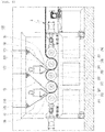
- FIG. 4 schematically illustrates a partial configuration of a case manufacturing device 100 according to another embodiment of the present disclosure.
- FIG. 5 is an exploded perspective view schematically illustrating a multilayer sheet 3 according to another embodiment of the present disclosure.
- FIG. 6 is an exploded perspective view schematically illustrating a multilayer sheet 3 according to still another embodiment of the present disclosure.
- the multilayer sheet 3 is expressed in a line type in FIG. 4 , the multilayer sheet 3 has a width in a direction parallel with the rotating shafts 311, 321, 331, 341, and 351 of respective rollers 310, 320, 330, 340, and 350.
- FIG. 5 is for the purpose of illustrating the laminated configuration of the multilayer sheet 3.
- the first fabric 10, the second fabric 40, the third fabric 50, the first resin 20, and the second resin 30 may be configured in forms different from those illustrated in FIG. 5 , and may also have sizes larger than those illustrated in FIG. 5 .
- the case manufacturing device 100 includes a first fabric supply portion 110, a first resin supply portion 210, a first roller 310, a second roller 320, a second resin supply portion 220, a third roller 330, a fourth roller 340, and a fifth roller 350, as described above.
- the case manufacturing device 100 may further include a second fabric supply portion 120 and a third fabric supply portion 130.
- the first fabric supply portion 110, the first resin supply portion 210, the first roller 310, the second roller 320, the second resin supply portion 220, the third roller 330, the fourth roller 340, the fifth roller 350, the first fabric 10, the first resin 20, and the second resin 30 may be configured in the same manner as described with reference to FIG. 2 and FIG. 3 .
- the second fabric supply portion 120 is configured to continuously supply a second fabric 40.
- the second fabric 40 is formed by coupling of fibers, and has multiple through-holes 43 that penetrate the fabric.
- the second fabric 40 is configured in a thin cloth type and has through-holes 43 that penetrate the same from one surface to the other surface thereof. Such through-holes 43 are repeatedly arranged throughout the entire area of the second fabric 40.
- the second fabric 40 according to the present disclosure may be made of a woven material, a knitted material, a non-woven fabric, or a combination thereof. Particularly, the second fabric 40 is preferably made of a woven material.
- the material, size, and shape of the second fabric 40 may differ from those of the first fabric 10, but are preferably configured in the same manner. Accordingly, detailed descriptions of the second fabric 40 identical to those of the first fabric 10 will be omitted herein.
- the second fabric 40 supplied from the second fabric supply portion 120 is continuously supplied between the first roller 310 and the second roller 320 and, after passing between the first roller 310 and the second roller 320, moves so as to surround the outer peripheral surface of the second roller 320.
- the case manufacturing device 100 is configured such that, in connection with supplying the second fabric 40 between the first roller 310 and the second roller 320, the second fabric 40 is positioned opposite the first fabric 10 with reference to the first resin 20 such that the second fabric 40 directly contacts the outer peripheral surface of the first roller 310, and the first resin 20 is coupled to the second fabric 40 and to the first fabric 10 so as to be interposed between the second fabric 40 and the first fabric 10.
- the thickness of the first resin 20 discharged from the nozzle of the first resin supply portion 210 is t1
- the thickness of the first fabric 10 supplied from the first fabric supply portion 110 is t2
- the thickness of the second fabric 40 supplied from the second fabric supply portion 120 is t6
- the gap between the first roller 310 and the second roller 320 is t3'
- t3' is preferably smaller than the sum of t1, t2 and t6.
- the coupling between the second fabric 40 and the first resin 20 proceeds in the same manner as that of the coupling between the first fabric 10 and the first resin 20 described above.
- the second fabric 40, the first resin 20, and the first fabric 10 are successively laminated and coupled while passing through the gap between the first roller 310 and the second roller 320, and the same then move in a predetermined range while being forced against the outer peripheral surface of the second roller 320.
- the surface temperature of the second roller 320 is preferably identical to the surface temperature of the first roller 310.
- the surface temperature of the first roller 310 and that of the second roller 320 are preferably about 70°C.
- the third fabric supply portion 130 is configured to continuously supply a third fabric 50.
- the third fabric 50 is formed by coupling of fibers, and has multiple through-holes 53 that penetrate the fabric.
- the third fabric 50 is configured in a thin cloth type and has through-holes 53 that penetrate the same from one surface to the other surface thereof. Such through-holes 53 are repeatedly arranged throughout the entire area of the third fabric 50.
- the third fabric 50 may be made of a woven material, a knitted material, a non-woven fabric, or a combination thereof. Particularly, the third fabric 50 is preferably made of a woven material.
- the material, size, and shape of the third fabric 50 may differ from those of the first fabric 10, but are preferably configured in the same manner. Accordingly, detailed descriptions of the third fabric 50 identical to those of the first fabric 10 will be omitted herein.
- the third fabric 50 supplied from the third fabric supply portion 130 is continuously supplied between the third roller 330 and the fourth roller 340 and, after passing between the third roller 330 and the fourth roller 340, moves so as to surround the outer peripheral surface of the fourth roller 340.
- the case manufacturing device 100 is configured such that, in connection with supplying the third fabric 50 between the third roller 330 and the fourth roller 340, the third fabric 50 is positioned opposite the first fabric 10 with reference to the second resin 30 such that the third fabric 50 directly contacts the outer peripheral surface of the fourth roller 340, and the second resin 30 is coupled to the first fabric 30 and to the third fabric 50 so as to be interposed between the first fabric 10 and the third fabric 50.
- the thickness of the first resin 20 discharged from the nozzle of the first resin supply portion 210 is t1
- the thickness of the fabric 10 supplied from the first fabric supply portion 110 is t2
- the thickness of the second resin 30 discharged from the nozzle of the second resin supply portion 220 is t4
- the thickness of the second fabric 40 supplied from the second fabric supply portion 120 is t6
- the thickness of the third fabric 50 supplied from the third fabric supply portion 130 is t7
- the gap between the third roller 330 and the fourth roller 340 is t5'
- t5' is preferably smaller than the sum of t1, t2, t4, t6, and t7.
- the coupling between the third fabric 50 and the second resin 30 proceeds in the same manner as that of the coupling between the first fabric 10 and the second resin 30 described above.
- the second fabric 40, the first resin 20, the first fabric 10, the second resin 30, and the third fabric 50 are successively laminated and coupled while passing through the gap between the third roller 330 and the fourth roller 340, and the same then move in a predetermined range while being forced against the outer peripheral surface of the fourth roller 340.
- the second fabric 40, the first resin 20, the first fabric 10, and the second resin 30 are coupled to one another while passing through the first roller 310, the second roller 320, the third roller 330, and the fourth roller 340 (as well as the fifth roller 350), thereby manufacturing a multilayer sheet 3.
- first resin 20, the first fabric 10, the second resin 30, and the third fabric 50 are coupled to one another while passing through the first roller 310, the second roller 320, the third roller 330, and the fourth roller 340 (as well as the fifth roller 350), thereby manufacturing a multilayer sheet 3.
- the second fabric 40, the first resin 20, the first fabric 10, the second resin 30, and the third fabric 50 are coupled to one another while passing through the first roller 310, the second roller 320, the third roller 330, and the fourth roller 340 (as well as the fifth roller 350), thereby manufacturing a multilayer sheet 3.
- the multilayer sheet 3 according to the present disclosure further includes a second fabric 40 and/or a third fabric 50. Accordingly, it is possible to form a multilayer sheet 3, a case 2, and a travel bag 1 that are more robust, and to form a product having excellent tensile strength and impact strength.
- the second fabric 40 and/or the third fabric 50 can overlap with the first fabric 10 and exhibit a unique aesthetic appearance. This makes it possible to form a multilayer sheet 3, a case 2, and a travel bag 1 with aesthetic appearances.
- the multilayer sheet 3 After passing through the fourth roller 340 and the fifth roller 350, the multilayer sheet 3 is transferred and cooled, and is then cut into a predetermined size suitable for manufacture of each case 2.
- case manufacturing device 100 may further include a separate resin supply portion (not illustrated) in addition to the first resin supply portion 210 and the second resin supply portion 220.
- a multilayer sheet 3 manufactured accordingly may further include a separate resin layer 60 as illustrated in FIG. 6 .
- FIG. 7 schematically illustrates a partial configuration of a case manufacturing device 100 according to the present disclosure.
- the case manufacturing device 100 may further include a sheet clamp 400, a preheater 500, and a molding machine 600.
- a series of continuous multilayer sheets 3 are cooled and then cut into predetermined sizes, respectively.
- the multilayer sheets 3 that have been cut into predetermined sizes are molded into cases 2, respectively.
- the multilayer sheets 3 are preferably cut in the shape of quadrangular plates.
- the sheet clamp 400 is configured to hold the edge of a multilayer sheet 3 and has the shape of a quadrangular frame.
- the sheet clamp 400 may be divided into a first clamp 410 and a second clamp 420.
- the first clamp 410 and the second clamp 420 may be configured as quadrangular frames having the same size and shape, and may be coupled to each other so as to support the edge of a multilayer sheet 3 that has been cut in a quadrangular shape (the edge of a quadrangular multilayer sheet 3 is interposed between the first clamp 410 and the second clamp 420).
- One corner of each of the first clamp 410 and the second clamp 420 may be hinge-coupled.
- the preheater 500 has multiple slots 510 into which the sheet clamp 400 is inserted, and is configured such that a hot wind is supplied and circulated therein. Particularly, the preheater 500 is configured such that multiple multilayer sheets 3 held by sheet clamps 400 can be inserted therein.
- the multiple slots 510 of the preheater 500 are arranged to be spaced apart from each other in the leftward/rightward direction, and respective slots 510 are preferably elongated in the vertical direction. This guarantees that a hot wind efficiently circulates inside the preheater 500.
- a boiler and a blower may be formed inside the preheater 500, thereby steadily heating multiple sheet clamps 400 inserted into the preheater 500.
- the multilayer sheets 3 heated inside the preheater 500 are again withdrawn from the preheater 500 while being held by the sheet clamps 400, and are then molded in the shape of cases 2 by the molding machine 600.
- the molding machine 600 is configured in a conventional press molding machine type, and may include a first mold 610 and a second mold 620 combined with each other with a multilayer sheet 3 interposed between the same.
- a multilayer sheet including a fabric and a resin, a case of a travel bag including the sheet, and a device for manufacturing the same, according to the present disclosure, are for the purpose of manufacturing a travel bag in a card case type, the strength of which can be further improved. Not only the tensile strength and impact strength of the entire multilayer sheet can be improved substantially and become advantageous, the aesthetic appearance and naturalness unique to the first fabric can be directly seen from and embedded in the manufactured case. It is possible to provide a travel bag with an excellent quality even if the manufacturing cost and manufacturing process are reduced. Considering this, the present disclosure is beyond the limits of conventional technologies and, besides uses regarding relevant technologies, devices to which the present disclosure is applied have a sufficient potential for commercial availability or marketing. It would also be obvious that the present disclosure could be implemented practically. Therefore, the present disclosure has an industrial applicability.
Landscapes
- Engineering & Computer Science (AREA)
- Mechanical Engineering (AREA)
- Chemical & Material Sciences (AREA)
- Composite Materials (AREA)
- Textile Engineering (AREA)
- Materials Engineering (AREA)
- Laminated Bodies (AREA)
- Purses, Travelling Bags, Baskets, Or Suitcases (AREA)
Applications Claiming Priority (3)
| Application Number | Priority Date | Filing Date | Title |
|---|---|---|---|
| KR1020160075037A KR101691178B1 (ko) | 2016-06-16 | 2016-06-16 | 원단과 수지를 포함하는 멀티레이어시트, 이에 의하여 이루어지는 여행용 가방의 케이스 및 그 제조장치 |
| KR1020160162858A KR101798512B1 (ko) | 2016-12-01 | 2016-12-01 | 원단과 수지를 포함하는 멀티레이어시트, 이에 의하여 이루어지는 여행용 가방의 케이스, 그 제조방법 및 그 제조장치 |
| PCT/KR2017/006243 WO2017217783A1 (ko) | 2016-06-16 | 2017-06-15 | 원단과 수지를 포함하는 멀티레이어시트, 이에 의하여 이루어지는 여행용 가방의 케이스 및 그 제조장치 |
Publications (2)
| Publication Number | Publication Date |
|---|---|
| EP3473129A1 true EP3473129A1 (de) | 2019-04-24 |
| EP3473129A4 EP3473129A4 (de) | 2020-02-19 |
Family
ID=60664368
Family Applications (1)
| Application Number | Title | Priority Date | Filing Date |
|---|---|---|---|
| EP17813606.5A Withdrawn EP3473129A4 (de) | 2016-06-16 | 2017-06-15 | Mehrschichtige folie mit gewebe und harz, reisetasche daraus und vorrichtung zur herstellung davon |
Country Status (4)
| Country | Link |
|---|---|
| US (1) | US20200093234A1 (de) |
| EP (1) | EP3473129A4 (de) |
| CN (1) | CN109310190A (de) |
| WO (1) | WO2017217783A1 (de) |
Cited By (3)
| Publication number | Priority date | Publication date | Assignee | Title |
|---|---|---|---|---|
| WO2021058714A1 (en) * | 2019-09-25 | 2021-04-01 | Covestro Intellectual Property Gmbh & Co. Kg | Thermoplastic composite sheet and prepartion method therefor and article made therefrom |
| EP3848192A1 (de) * | 2020-01-10 | 2021-07-14 | Covestro Deutschland AG | Thermoplastische verbundfolie und herstellungsverfahren dafür und daraus hergestellter artikel |
| GB2623852A (en) * | 2022-10-31 | 2024-05-01 | Cygnet Texkimp Ltd | Compactor assembly |
Families Citing this family (5)
| Publication number | Priority date | Publication date | Assignee | Title |
|---|---|---|---|---|
| CN108819289A (zh) * | 2018-08-06 | 2018-11-16 | 泰安石英复合材料有限公司 | 一种行李箱箱体的制造生产线及制造方法 |
| EP3833210A1 (de) * | 2018-08-10 | 2021-06-16 | Louis Vuitton Malletier | Verfahren zur herstellung einer starren gepäckschale, gepäckschale und gepäck |
| CN110696386A (zh) * | 2019-09-26 | 2020-01-17 | 安徽天恩旅行用品科技有限公司 | 一种硬质行李箱外壳制造工艺 |
| CN111572059B (zh) * | 2020-05-13 | 2021-07-06 | 株洲时代工程塑料科技有限责任公司 | 一种连续玻纤增强热塑性复合材料及其制备方法 |
| CN120751634A (zh) * | 2024-06-19 | 2025-10-03 | 荣耀终端股份有限公司 | 结构件及其制备方法、电子设备 |
Family Cites Families (11)
| Publication number | Priority date | Publication date | Assignee | Title |
|---|---|---|---|---|
| JPH0633107B2 (ja) * | 1983-12-28 | 1994-05-02 | 富士写真フイルム株式会社 | 包装材料 |
| ATE89461T1 (de) * | 1987-08-28 | 1993-06-15 | Gates Formed Fibre Products | Halbsteife gepaeckschale und verfahren zu ihrer herstellung. |
| US6475932B1 (en) * | 1999-01-29 | 2002-11-05 | Ato Findley, Inc. | High strength through-bonding technique for elastomeric laminates |
| JP2004024433A (ja) * | 2002-06-24 | 2004-01-29 | Iris Ohyama Inc | 鞄及び収納ボックス並びにその製造方法 |
| KR100821322B1 (ko) * | 2007-02-21 | 2008-04-11 | 김소자 | 합성수지시트를 제조하는 장치 및 이에 사용되는 롤러 장치 |
| KR101067507B1 (ko) * | 2008-08-28 | 2011-09-27 | 심재훈 | 쇼핑 백 원단 및 엠보스드 쇼핑백 |
| KR101934602B1 (ko) * | 2010-10-29 | 2019-01-02 | 삼소나이트 아이피 홀딩스 에스.에이.알.엘. | 수화물 케이스의 다중재료 구조와 그 제조방법 |
| TWM479216U (zh) * | 2013-07-31 | 2014-06-01 | Cheng-Sheng Chen | 多層複合材料 |
| IN2014MU00164A (de) * | 2014-01-17 | 2015-04-24 | Kamakshi Flexiprints Pvt Ltd | |
| TWM522610U (zh) * | 2016-03-16 | 2016-06-01 | Jian-Zhi Chen | 花樣旅行箱 |
| KR101691178B1 (ko) * | 2016-06-16 | 2016-12-30 | 주식회사 캐리맥스통상 | 원단과 수지를 포함하는 멀티레이어시트, 이에 의하여 이루어지는 여행용 가방의 케이스 및 그 제조장치 |
-
2017
- 2017-06-15 US US16/310,347 patent/US20200093234A1/en not_active Abandoned
- 2017-06-15 EP EP17813606.5A patent/EP3473129A4/de not_active Withdrawn
- 2017-06-15 WO PCT/KR2017/006243 patent/WO2017217783A1/ko not_active Ceased
- 2017-06-15 CN CN201780034741.3A patent/CN109310190A/zh active Pending
Cited By (4)
| Publication number | Priority date | Publication date | Assignee | Title |
|---|---|---|---|---|
| WO2021058714A1 (en) * | 2019-09-25 | 2021-04-01 | Covestro Intellectual Property Gmbh & Co. Kg | Thermoplastic composite sheet and prepartion method therefor and article made therefrom |
| EP3848192A1 (de) * | 2020-01-10 | 2021-07-14 | Covestro Deutschland AG | Thermoplastische verbundfolie und herstellungsverfahren dafür und daraus hergestellter artikel |
| GB2623852A (en) * | 2022-10-31 | 2024-05-01 | Cygnet Texkimp Ltd | Compactor assembly |
| GB2623852B (en) * | 2022-10-31 | 2025-01-15 | Cygnet Texkimp Ltd | Compactor assembly |
Also Published As
| Publication number | Publication date |
|---|---|
| US20200093234A1 (en) | 2020-03-26 |
| CN109310190A (zh) | 2019-02-05 |
| EP3473129A4 (de) | 2020-02-19 |
| WO2017217783A1 (ko) | 2017-12-21 |
Similar Documents
| Publication | Publication Date | Title |
|---|---|---|
| EP3473129A1 (de) | Mehrschichtige folie mit gewebe und harz, reisetasche daraus und vorrichtung zur herstellung davon | |
| ES2315319T3 (es) | Transferible afelpado y articulo de fabricacion que incluye la aplicacion del transferible mediante pelicula polimerica termoplastica. | |
| JP7037200B2 (ja) | ニードルパンチ不織布の製造方法 | |
| KR101691178B1 (ko) | 원단과 수지를 포함하는 멀티레이어시트, 이에 의하여 이루어지는 여행용 가방의 케이스 및 그 제조장치 | |
| CN102666085A (zh) | 成形体、衣料品、层叠体的制造方法及成形体的制造方法 | |
| EP0685014A1 (de) | Verbundkörper. | |
| KR101242139B1 (ko) | 입체 무늬형성 합성수지시트 및 그 제조장치와 제조방법 | |
| KR20190127551A (ko) | 승화 잉크로 인쇄하기 위한 층상 물품 및 그 제조 방법 | |
| US20190118505A1 (en) | Decorative Sheet, Emboss Processing Method and Emboss Processing Mold | |
| TW201912884A (zh) | 薄膜立體網布及其製造方法 | |
| KR101798512B1 (ko) | 원단과 수지를 포함하는 멀티레이어시트, 이에 의하여 이루어지는 여행용 가방의 케이스, 그 제조방법 및 그 제조장치 | |
| KR101523518B1 (ko) | 직물지 원단의 부분 엠보싱 제조방법 | |
| KR20110000088U (ko) | 친환경 우레탄 시트 | |
| KR20170078298A (ko) | 합성피혁용 복합시트 | |
| KR102534138B1 (ko) | 가죽 질감을 가지는 원단 및 그 제조방법 | |
| KR20190137713A (ko) | 동조엠보 바닥재 제조방법 및 이 제조방법에 의해 제조된 바닥재 | |
| KR101006533B1 (ko) | 기능성 원단 | |
| CN114851674A (zh) | 一种复合型再生防水布料制造方法、再生防水布料及制品 | |
| JP3546433B2 (ja) | 装飾シートの製造法 | |
| TW201127601A (en) | Decorated molded article, process for producing same, and laminate used therefor | |
| US12600080B2 (en) | Digital printed 3-D patterned emblem with graphics for soft goods | |
| KR100943290B1 (ko) | 천연피혁 질감의 직물 및 그 제조방법 | |
| KR20020082382A (ko) | 직물의 입체무늬 성형장치 | |
| KR100726285B1 (ko) | 폴리염화비닐 원단 인쇄 방법 | |
| KR200243307Y1 (ko) | 입체문양 직물지 |
Legal Events
| Date | Code | Title | Description |
|---|---|---|---|
| STAA | Information on the status of an ep patent application or granted ep patent |
Free format text: STATUS: THE INTERNATIONAL PUBLICATION HAS BEEN MADE |
|
| PUAI | Public reference made under article 153(3) epc to a published international application that has entered the european phase |
Free format text: ORIGINAL CODE: 0009012 |
|
| STAA | Information on the status of an ep patent application or granted ep patent |
Free format text: STATUS: REQUEST FOR EXAMINATION WAS MADE |
|
| 17P | Request for examination filed |
Effective date: 20181126 |
|
| AK | Designated contracting states |
Kind code of ref document: A1 Designated state(s): AL AT BE BG CH CY CZ DE DK EE ES FI FR GB GR HR HU IE IS IT LI LT LU LV MC MK MT NL NO PL PT RO RS SE SI SK SM TR |
|
| AX | Request for extension of the european patent |
Extension state: BA ME |
|
| DAV | Request for validation of the european patent (deleted) | ||
| DAX | Request for extension of the european patent (deleted) | ||
| A4 | Supplementary search report drawn up and despatched |
Effective date: 20200117 |
|
| RIC1 | Information provided on ipc code assigned before grant |
Ipc: B44C 5/00 20060101ALI20200113BHEP Ipc: B29C 48/15 20190101ALI20200113BHEP Ipc: A45C 5/00 20060101ALI20200113BHEP Ipc: B32B 37/15 20060101AFI20200113BHEP |
|
| STAA | Information on the status of an ep patent application or granted ep patent |
Free format text: STATUS: THE APPLICATION HAS BEEN WITHDRAWN |
|
| 18W | Application withdrawn |
Effective date: 20200703 |