EP3473141B1 - Knife holder with sharpening system - Google Patents
Knife holder with sharpening system Download PDFInfo
- Publication number
- EP3473141B1 EP3473141B1 EP18200579.3A EP18200579A EP3473141B1 EP 3473141 B1 EP3473141 B1 EP 3473141B1 EP 18200579 A EP18200579 A EP 18200579A EP 3473141 B1 EP3473141 B1 EP 3473141B1
- Authority
- EP
- European Patent Office
- Prior art keywords
- base
- knife holder
- sharpening
- storage position
- piston
- Prior art date
- Legal status (The legal status is an assumption and is not a legal conclusion. Google has not performed a legal analysis and makes no representation as to the accuracy of the status listed.)
- Active
Links
Images


Classifications
-
- A—HUMAN NECESSITIES
- A47—FURNITURE; DOMESTIC ARTICLES OR APPLIANCES; COFFEE MILLS; SPICE MILLS; SUCTION CLEANERS IN GENERAL
- A47J—KITCHEN EQUIPMENT; COFFEE MILLS; SPICE MILLS; APPARATUS FOR MAKING BEVERAGES
- A47J47/00—Kitchen containers, stands or the like, not provided for in other groups of this subclass; Cutting-boards, e.g. for bread
- A47J47/16—Stands, or holders for kitchen articles
-
- A—HUMAN NECESSITIES
- A47—FURNITURE; DOMESTIC ARTICLES OR APPLIANCES; COFFEE MILLS; SPICE MILLS; SUCTION CLEANERS IN GENERAL
- A47G—HOUSEHOLD OR TABLE EQUIPMENT
- A47G21/00—Table-ware
- A47G21/14—Knife racks or stands; Holders for table utensils attachable to plates
-
- B—PERFORMING OPERATIONS; TRANSPORTING
- B24—GRINDING; POLISHING
- B24B—MACHINES, DEVICES, OR PROCESSES FOR GRINDING OR POLISHING; DRESSING OR CONDITIONING OF ABRADING SURFACES; FEEDING OF GRINDING, POLISHING, OR LAPPING AGENTS
- B24B3/00—Sharpening cutting edges, e.g. of tools; Accessories therefor, e.g. for holding the tools
- B24B3/36—Sharpening cutting edges, e.g. of tools; Accessories therefor, e.g. for holding the tools of cutting blades
-
- B—PERFORMING OPERATIONS; TRANSPORTING
- B24—GRINDING; POLISHING
- B24B—MACHINES, DEVICES, OR PROCESSES FOR GRINDING OR POLISHING; DRESSING OR CONDITIONING OF ABRADING SURFACES; FEEDING OF GRINDING, POLISHING, OR LAPPING AGENTS
- B24B41/00—Component parts such as frames, beds, carriages, headstocks
- B24B41/06—Work supports, e.g. adjustable steadies
Definitions
- the present invention relates to a support for holding cutlery items, comprising in particular knives and/or other utensils, for example scissors.
- the present invention relates more particularly to a knife holder, such as a knife block, comprising a system for sharpening a knife blade.
- a knife blade After repeated use, a knife blade requires to improve the cutting performance of the blade. Thus, it is important to have a sharpening accessory that is available in the kitchen in order to regularly sharpen the blade to restore its cutting performance.
- a knife holder comprising a frame, a holding device intended to receive knives, and a sharpening system intended to sharpen a blade of said knives.
- the sharpening system comprises a base and at least one sharpening member which is secured to the base.
- the base is movable relative to the frame between a storage position in which the base is inside the frame and a gripping position in which the base is removed from the frame.
- other knife storage blocks incorporating sharpening devices from the documents US2013/306500 And EP 3189753 .
- the base of such a sharpening system is retractable from the knife holder.
- the base is rotatably mounted on the frame between its storage position in which the sharpening member is stored inside the frame and is not accessible to perform a sharpening operation and a gripping position in which the sharpening member is out of the frame and can be engaged by a blade.
- Such a knife holder has a sharpening system that can be deployed to perform a knife blade sharpening operation and which can also be stowed and stored in the frame for the rest of the time.
- the base of such a sharpening system is integral with the frame, that is to say there always remains a physical attachment between the sharpening system and the frame and cannot be separated from the frame.
- the user is forced to carry out a blade sharpening operation at a specific location near the knife holder, with limited accessibility.
- the object of the present invention is to remedy the aforementioned drawbacks and to propose a knife holder with a removable sharpening system, which can be removed or removed from the knife holder, having improved ergonomics for safer use.
- Another object of the invention is to provide a knife support with sharpening system having a design that is simple and economical to implement.
- a knife holder comprising a frame, a holding device intended to receive knives, and a sharpening system intended to sharpen a blade of said knives, the sharpening system comprising a base and at least one member sharpening which is secured to the base, the base being movable relative to the frame between a storage position in which the base is inside the frame and a gripping position in which the base is partially removed from the frame, the base being held to the sharpening system by at least one magnetic element, the base being able to be separated from the knife support without a physical link when it is in its gripping position to carry out an operation blade sharpening.
- the base provided with at least one sharpening member can be both stored and stored in the frame of the support to save storage space in the kitchen, and separated from the support to allow the user to carry out a knife blade sharpening operation in good conditions of use in a suitable place, for example on the edge of a work surface.
- the sharpening system is not attached to the frame, that is to say it can be removed and become independent of the frame, so there remains no physical attachment between the sharpening system and the frame.
- holding the base by at least one magnetic element is very simple and intuitive to use.
- the base When the base is held in the sharpening system in its gripping position, the user can easily and quickly separate the base from the support by making a simple gesture.
- the base which is partially removed from the frame, has a grip zone that the user can easily grasp.
- the base is held to the sharpening system by two magnetic elements or by a magnetic element and a ferromagnetic element.
- Either one of the two magnetic elements or either the magnetic element or the ferromagnetic element is secured to the frame and the other element is secured to the base.
- the two elements are configured to attract each other in order to maintain the base in the support.
- the base is movable in translation relative to the frame between its storage position and its gripping position.
- the user pushes the base to move it from its storage position to its gripping position where he then applies an additional force in order to overcome the force of attraction of the at least one magnetic element in order to separate the support base.
- the user approaches the base towards its gripping position in which the base is attracted and held to the support by the at least one magnetic element. The user then pushes the base to move it from its gripping position to its storage position.
- the base is movable in translation along a transverse direction perpendicular to a direction of vertical extension of the frame.
- the base when the frame is placed on a horizontal plane, the base can be removed and stored horizontally.
- the sharpening system comprises a retractable mechanism of the retractable ballpoint pen type, pressure applied to the base in its storage position allowing it to pass into its gripping position, and vice versa.
- the use of the retractable mechanism of the retractable ballpoint pen type makes it possible to maneuver the base quickly between its storage position and its gripping position, by simply pushing on the base.
- the retractable ballpoint pen type retractable mechanism is a compact and efficient system.
- the retractable mechanism comprises a plug, a cam and a piston, the piston being movable in translation relative to the frame between a retracted position in which the base is in its storage position and an extended position in which the base is in his position of gripping, the base being held to the piston by the at least one magnetic element.
- the base follows the translational movement of the piston of the retractable mechanism when the base is held to the piston by the at least one magnetic element.
- the at least one magnetic element is integral with the piston, and the base comprises a ferromagnetic plate, the at least one magnetic element exerting a force of attraction on the ferromagnetic plate to hold the base to the piston.
- the surface of the ferromagnetic plate is larger than that of the at least one magnetic element.
- the ferromagnetic plate does not need to be positioned perfectly in the center of the piston to ensure good contact holding the base.
- such a construction makes it possible to absorb the manufacturing and positioning tolerances of the ferromagnetic plate while ensuring good retention by the at least one magnetic element. Consequently, such a construction is inexpensive and easy to implement.
- the base comprises a plastic body, the ferromagnetic plate being arranged inside the plastic body.
- the ferromagnetic plate is made of a ferromagnetic material which may be sensitive to oxidation. Thus, the ferromagnetic plate is protected by the plastic body against oxidation.
- the sharpening system comprises a device for holding the base in its storage position.
- the piston of the retracting mechanism is not held in position when it is in its retracted position. Indeed, the piston in the retracted position has a free stroke due to the construction of the retractable mechanism.
- the base is integral with the piston when it is in the storage position. Thus, the base also presents the free run in its storage position.
- the holding device makes it possible to hold the base in its storage position and to prevent it from moving on its free travel. Consequently, the base is immobilized in its storage position thanks to the holding device.
- the holding device comprises a slat, one free end of which is provided with a protrusion as well as a boss placed on a bottom wall of the base, the protuberance cooperating with the boss to make it possible to hold the base when it is in its storage position.
- the protuberance at the free end of the slat is arranged behind the boss when the base is in its storage position, making it possible to block the base in its storage position.
- the elastic deformation of the lamella allows the protrusion to pass below the boss so that the base leaves its storage position towards its gripping position when the piston passes from its in position to its out position.
- the retractable mechanism is removable without tools from the knife holder.
- the retractable mechanism is designed to be easily disassembled without tools for cleaning, replacement and/or repair of parts.
- the support 1 in the shape of a rectangular parallelepiped, has a holding device 3 which is intended to receive and hold cutlery items, in particular knives.
- the support 1 also comprises a frame 2 which extends along a direction of extension 22 vertical.
- the holding device 3 is arranged above the frame 2 in a removable manner via a clipping system 32.
- the frame 2 comprises a side wall 20 which is made of a transparent material such as glass or styrene-acrylonitrile copolymer (SAN) to allow the user to recognize the type of knife inserted into the frame 2 through the side wall 20.
- SAN styrene-acrylonitrile copolymer
- the support 1 comprises a system 4 for sharpening the knife blade which is arranged on a lower part of the support 1, below the frame 2.
- the sharpening system 4 comprises a base 44 which is arranged below the frame 2.
- the base 44 is removable from the frame 2 to facilitate cleaning of the entire sharpening system 4.
- the sharpening system 4 comprises a base 40 which is arranged inside the base 44.
- the base 40 is movable in translation relative to the base 44 in a transverse direction 11 perpendicular to the vertical direction of extension 22 of the frame 2.
- the base 40 is movable between a position storage in which the base 40 is inside the frame 2 as illustrated in figure 2 , 4 and a gripping position in which the base 40 is partially removed from the frame 2 as illustrated in figure 3 , 5 .
- the sharpening system 4 comprises a retractable mechanism 42 which is arranged on a side wall 440 of the base 44.
- the retractable mechanism 42 is a system of the retractable ballpoint pen type.
- the retractable mechanism 42 includes a spring 42D, a cam 42B, a plug 42A and a piston 42C.
- the principle of such a retractable mechanism is well known to those skilled in the art, in particular in the document US3137276 . Thus, we will not detail in the present invention the principle of the retractable mechanism 42.
- the retracting mechanism 42 includes a disc-shaped magnetic element 41 which is arranged in a cylindrical cavity 42c of the piston 42C.
- magnetic element we understand a permanent magnet which can exert an attraction force on any ferromagnetic material.
- the magnetic element 41 can for example be a neodymium magnet.
- the base 40 comprises a ferromagnetic plate 401 which is arranged vertically on a bottom wall 435 of the base 40.
- the magnetic element 41 exerts an attraction force on the ferromagnetic plate 401 to allow the base 40 to be held to the piston 42C of the mechanism. retractable 42.
- the base 40 comprises a plastic body 402.
- the ferromagnetic plate 401 is arranged inside the plastic body 402.
- the plastic body 402 comprises an intermediate wall 402a which is placed between the magnetic element 41 and the ferromagnetic plate 401 in order to avoid direct contact between the magnetic element 41 and the ferromagnetic plate 401. Thus, the ferromagnetic plate 401 is protected by the plastic body 402 against oxidation.
- the piston 42C of the retractable mechanism 42 is movable in translation along the transverse direction 11 between an in position in which the base 40 is in its storage position and an out position in which the base 40 is in its gripping position.
- the base 40 follows the translational movement of the piston 42C when the base 40 is held to the piston 42C by the element magnetic 41.
- the retractable mechanism 42 makes it possible to maneuver the base 40 quickly between its storage position and its gripping position, by simply pushing on the plastic body 402 of the base 40.
- the sharpening system 4 comprises a device 43 for holding the base 40 in its storage position.
- the piston 42C of the retractable mechanism 42 is not held in position and has a free stroke due to the construction of the retractable mechanism 42.
- this free stroke of the piston 42C is in particular linked to the geometry of the grooves 42a of the plug 42A.
- the holding device 43 therefore makes it possible to hold the base 40 in its storage position and to prevent it from moving on its free stroke.
- the holding device 43 comprises a lamella 431, one free end 432 of which is provided with a protrusion 433 as well as a boss 434 arranged on the bottom wall 435 of the base 40.
- the protuberance 433 at the free end 432 of the strip 431 is arranged behind the boss 434 when the base 40 is in its storage position allowing the base 40 to be locked in its storage position.
- the spring 42D of the retractable mechanism 42 is configured to apply a return force on the base 40 to cause a deformation of the slat 431 allowing the protrusion 433 to pass below the boss 434 so that the base 40 leaves its storage position towards its gripping position.
- the sharpening system 4 comprises two sharpening members 40a which are installed on the base 40, the two sharpening members 40a being integral with the base 40.
- the two sharpening members 40a in the form of a cylinder are made made of a very hard material, for example tungsten.
- Each sharpening member 40a has an upper end 40H and a lower end 40B.
- a knife blade insertion inlet 40E is formed between two upper ends 40H of the two sharpening members 40a.
- the two sharpening members 40a are arranged side by side so that they form a V-shaped sharpening zone along a longitudinal direction 33 perpendicular to the transverse direction 11.
- the user when the user wishes to perform a sharpening operation of the blade of a knife, he first pushes with his finger in the transverse direction 11 on an outer surface 402b of the plastic body 402 of the base 40 in position of storage. Under the action of the user, the spring 42D of the retractable mechanism 42 is compressed to restore a return force on the base 40 to cause a deformation of the strip 431 allowing the protuberance 433 to pass below the boss 434. Thus, the base 40 leaves its storage position towards its gripping position.
- the user grasps a gripping zone of the plastic body 402 which has come out of the frame 2 and pulls the assembly of the base 40 in order to overcome the force of attraction of the magnetic element 41 to make it possible to separate the base 40 from the support 1.
- the user can carry the base 40 comprising the sharpening members 40a in a suitable place, for example on the edge of a work surface to carry out a sharpening operation of the blade of a knife.
- the user grasps the base 40 and approaches it towards its gripping position in the frame 2.
- the base 40 is then attracted and held to the retractable mechanism 42 by the magnetic element 41.
- the user pushes the base 40 to move it from its gripping position to its storage position and the protuberance 433 of the slat 431 passes behind the boss 434 in order to immobilize the base 40 in its storage position . Consequently, the base 40 is stored in the frame 2.
- the holding of the base to the sharpening system can be achieved by two magnetic elements which attract each other, one of which is fixed to the base and the other is fixed to the retractable mechanism.
- the base is movable in translation along the direction of vertical extension of the frame.
Landscapes
- Engineering & Computer Science (AREA)
- Mechanical Engineering (AREA)
- Food Science & Technology (AREA)
- Finish Polishing, Edge Sharpening, And Grinding By Specific Grinding Devices (AREA)
- Knives (AREA)
- Workshop Equipment, Work Benches, Supports, Or Storage Means (AREA)
- Crystals, And After-Treatments Of Crystals (AREA)
- Processing Of Stones Or Stones Resemblance Materials (AREA)
Description
La présente invention concerne un support pour maintenir des articles de coutellerie, comprenant notamment des couteaux et/ou d'autres ustensiles, par exemple des ciseaux. La présente invention concerne plus particulièrement un support de couteaux, tel qu'un bloc-couteau, comportant un système d'affûtage d'une lame de couteaux.The present invention relates to a support for holding cutlery items, comprising in particular knives and/or other utensils, for example scissors. The present invention relates more particularly to a knife holder, such as a knife block, comprising a system for sharpening a knife blade.
On notera que, dans ce document, les termes « longitudinal », « transversal », « horizontal », « vertical », « inférieur », « supérieur », « haut », « bas », employés pour décrire le support, font référence à ce support en situation d'usage, lorsqu'il est posé sur un plan horizontal.It should be noted that, in this document, the terms "longitudinal", "transverse", "horizontal", "vertical", "lower", "upper", "top", "bottom", used to describe the support, refer to this support in use, when placed on a horizontal plane.
Après une utilisation répétée, une lame de couteau nécessite afin d'améliorer les performances de coupe de la lame. Ainsi, il est important d'avoir un accessoire d'affûtage qui est disponible dans la cuisine afin d'affûter régulièrement la lame pour restaurer sa performance de coupe.After repeated use, a knife blade requires to improve the cutting performance of the blade. Thus, it is important to have a sharpening accessory that is available in the kitchen in order to regularly sharpen the blade to restore its cutting performance.
Il est connu du document
Le socle d'un tel système d'affûtage est escamotable du support de couteaux. Le socle est monté en rotation sur le bâti entre sa position de rangement dans laquelle l'organe d'affûtage est rangé à l'intérieur du bâti et n'est pas accessible pour effectuer une opération d'affûtage et une position de préhension dans laquelle l'organe d'affûtage est sorti du bâti et peut être engagé par une lame. Un tel support de couteau comporte un système d'affûtage qui peut être déployé pour effectuer une opération d'affûtage de la lame de couteaux et qui peut être aussi rangé et stocké dans le bâti pendant le reste du temps.The base of such a sharpening system is retractable from the knife holder. The base is rotatably mounted on the frame between its storage position in which the sharpening member is stored inside the frame and is not accessible to perform a sharpening operation and a gripping position in which the sharpening member is out of the frame and can be engaged by a blade. Such a knife holder has a sharpening system that can be deployed to perform a knife blade sharpening operation and which can also be stowed and stored in the frame for the rest of the time.
Cependant, le socle d'un tel système d'affûtage est solidaire du bâti, c'est-à-dire qu'il reste toujours un attachement physique entre le système d'affûtage et le bâti et ne peut être séparé du bâti. L'utilisateur est obligé d'effectuer une opération d'affûtage de la lame à un endroit précis près du support de couteaux, avec une accessibilité limitée.However, the base of such a sharpening system is integral with the frame, that is to say there always remains a physical attachment between the sharpening system and the frame and cannot be separated from the frame. The user is forced to carry out a blade sharpening operation at a specific location near the knife holder, with limited accessibility.
De plus, lorsque le support est placé dans un endroit où l'espace est insuffisant pour que l'utilisateur puisse affûter la lame de couteaux, l'utilisateur doit déplacer l'ensemble du support qui est généralement lourd afin d'avoir plus d'espace pour réaliser l'opération d'affutage. Il est aussi dangereux pour l'utilisateur de porter un support rempli de couteaux et de le déplacer. Les couteaux risquent de glisser et tomber du support pendant son déplacement.In addition, when the stand is placed in a place where there is insufficient space for the user to sharpen the blade of knives, the user must move the whole stand which is usually heavy in order to have more space to carry out the sharpening operation. It is also dangerous for the user to carry a rack full of knives and move it. The knives may slip and fall from the holder while it is being moved.
Le but de la présente invention est de remédier aux inconvénients précités et de proposer un support de couteaux avec système d'affûtage amovible, qui peut être enlevé ou retiré du support de couteaux, présentant une ergonomie améliorée pour une utilisation plus sûre.The object of the present invention is to remedy the aforementioned drawbacks and to propose a knife holder with a removable sharpening system, which can be removed or removed from the knife holder, having improved ergonomics for safer use.
Un autre but de l'invention est de proposer un support de couteaux avec système d'affûtage présentant une conception simple et économique à mettre en oeuvre.Another object of the invention is to provide a knife support with sharpening system having a design that is simple and economical to implement.
Ces buts sont atteints avec un support de couteaux comportant un bâti, un dispositif de maintien destiné à recevoir des couteaux, et un système d'affûtage destiné à affûter une lame desdits couteaux, le système d'affûtage comprenant un socle et au moins un organe d'affûtage qui est solidaire du socle, le socle étant mobile par rapport au bâti entre une position de rangement dans laquelle le socle est à l'intérieur du bâti et une position de préhension dans laquelle le socle est partiellement sorti du bâti, le socle étant maintenu au système d'affûtage par au moins un élément magnétique, le socle pouvant être séparé du support de couteaux sans lien physique lorsqu'il est dans sa position de préhension pour effectuer une opération d'affûtage de la lame.These objects are achieved with a knife holder comprising a frame, a holding device intended to receive knives, and a sharpening system intended to sharpen a blade of said knives, the sharpening system comprising a base and at least one member sharpening which is secured to the base, the base being movable relative to the frame between a storage position in which the base is inside the frame and a gripping position in which the base is partially removed from the frame, the base being held to the sharpening system by at least one magnetic element, the base being able to be separated from the knife support without a physical link when it is in its gripping position to carry out an operation blade sharpening.
Avec une telle construction, le socle muni d'au moins un organe d'affûtage peut être à la fois rangé et stocké dans le bâti du support pour économiser de l'espace de rangement dans la cuisine, et séparé du support pour permettre à l'utilisateur d'effectuer une opération d'affûtage de la lame de couteaux dans de bonnes conditions d'utilisation dans un endroit adapté, par exemple sur le bord d'un plan de travail. Ainsi le système d'affûtage n'est pas solidaire du bâti, c'est-à-dire qu'il peut être enlevé et devenir indépendant du bâti, ainsi il ne reste aucun attachement physique entre le système d'affûtage et le bâti.With such a construction, the base provided with at least one sharpening member can be both stored and stored in the frame of the support to save storage space in the kitchen, and separated from the support to allow the user to carry out a knife blade sharpening operation in good conditions of use in a suitable place, for example on the edge of a work surface. Thus the sharpening system is not attached to the frame, that is to say it can be removed and become independent of the frame, so there remains no physical attachment between the sharpening system and the frame.
De plus, le maintien du socle par au moins un élément magnétique présente une utilisation très simple et intuitive. Lorsque le socle est maintenu au système d'affûtage dans sa position de préhension, l'utilisateur peut séparer facilement et rapidement le socle du support en faisant un simple geste.In addition, holding the base by at least one magnetic element is very simple and intuitive to use. When the base is held in the sharpening system in its gripping position, the user can easily and quickly separate the base from the support by making a simple gesture.
Par l'expression « positon de préhension », il faut comprendre au sens de l'invention que le socle qui est sorti partiellement du bâti, présente une zone de préhension que l'utilisateur peut facilement saisir.By the expression “grip position”, it should be understood within the meaning of the invention that the base, which is partially removed from the frame, has a grip zone that the user can easily grasp.
Par le terme « séparer », il faut comprendre au sens de l'invention détacher, disjoindre, dissocier, isoler, c'est-à-dire non lié physiquement ou indépendant.The term “separate” should be understood within the meaning of the invention to detach, disjoin, dissociate, isolate, that is to say not physically linked or independent.
De préférence, le socle est maintenu au système d'affûtage par deux éléments magnétiques ou par un élément magnétique et un élément ferromagnétique.Preferably, the base is held to the sharpening system by two magnetic elements or by a magnetic element and a ferromagnetic element.
Soit l'un des deux éléments magnétiques ou soit l'élément magnétique ou l'élément ferromagnétique est solidaire du bâti et l'autre élément est solidaire du socle. Les deux éléments sont configurés pour s'attirer afin de maintenir le socle dans le support.Either one of the two magnetic elements or either the magnetic element or the ferromagnetic element is secured to the frame and the other element is secured to the base. The two elements are configured to attract each other in order to maintain the base in the support.
De préférence, le socle est mobile en translation par rapport au bâti entre sa position de rangement et sa position de préhension.Preferably, the base is movable in translation relative to the frame between its storage position and its gripping position.
Ainsi, l'utilisateur pousse le socle pour le faire passer de sa position de rangement dans sa position de préhension où il applique ensuite une force supplémentaire afin de vaincre la force d'attraction de l'au moins un élément magnétique pour permettre de séparer le socle du support. Réciproquement, l'utilisateur approche le socle vers sa position de préhension dans laquelle le socle est attiré et maintenu au support par l'au moins un élément magnétique. L'utilisateur pousse ensuite le socle pour le faire passer de sa position de préhension dans sa position de rangement.Thus, the user pushes the base to move it from its storage position to its gripping position where he then applies an additional force in order to overcome the force of attraction of the at least one magnetic element in order to separate the support base. Conversely, the user approaches the base towards its gripping position in which the base is attracted and held to the support by the at least one magnetic element. The user then pushes the base to move it from its gripping position to its storage position.
De manière avantageuse, le socle est mobile en translation selon une direction transversale perpendiculaire à une direction d'extension verticale du bâti.Advantageously, the base is movable in translation along a transverse direction perpendicular to a direction of vertical extension of the frame.
Ainsi, lorsque le bâti est posé sur un plan horizontal, le socle peut être retiré et rangé horizontalement.Thus, when the frame is placed on a horizontal plane, the base can be removed and stored horizontally.
De préférence, le système d'affûtage comporte un mécanisme rétractable du type stylo à bille rétractable, une pression appliquée sur le socle dans sa position de rangement permettant de le faire passer dans sa position de préhension, et réciproquement.Preferably, the sharpening system comprises a retractable mechanism of the retractable ballpoint pen type, pressure applied to the base in its storage position allowing it to pass into its gripping position, and vice versa.
L'utilisation du mécanisme rétractable du type stylo à bille rétractable permet de manoeuvrer rapidement le socle entre sa position de rangement et sa position de préhension, en poussant simplement sur le socle. Le mécanisme rétractable du type stylo à bille rétractable est un système compact et efficace.The use of the retractable mechanism of the retractable ballpoint pen type makes it possible to maneuver the base quickly between its storage position and its gripping position, by simply pushing on the base. The retractable ballpoint pen type retractable mechanism is a compact and efficient system.
De plus, l'utilisation d'un tel mécanisme rétractable permet de ne pas avoir de bouton de préhension sur une face externe du socle.In addition, the use of such a retractable mechanism makes it possible not to have a gripping button on an external face of the base.
Dans une réalisation préférentielle, le mécanisme rétractable comporte un bouchon, une came et un piston, le piston étant mobile en translation par rapport au bâti entre une position rentrée dans laquelle le socle est dans sa position de rangement et une position sortie dans laquelle le socle est dans sa position de préhension, le socle étant maintenu au piston par l'au moins un élément magnétique.In a preferred embodiment, the retractable mechanism comprises a plug, a cam and a piston, the piston being movable in translation relative to the frame between a retracted position in which the base is in its storage position and an extended position in which the base is in his position of gripping, the base being held to the piston by the at least one magnetic element.
Le socle suit le mouvement en translation du piston du mécanisme rétractable lorsque le socle est maintenu au piston par l'au moins un élément magnétique.The base follows the translational movement of the piston of the retractable mechanism when the base is held to the piston by the at least one magnetic element.
De préférence, l'au moins un élément magnétique est solidaire du piston, et le socle comporte une plaque ferromagnétique, l'au moins un élément magnétique exerçant une force d'attraction sur la plaque ferromagnétique pour maintenir le socle au piston.Preferably, the at least one magnetic element is integral with the piston, and the base comprises a ferromagnetic plate, the at least one magnetic element exerting a force of attraction on the ferromagnetic plate to hold the base to the piston.
La surface de la plaque ferromagnétique est plus grande que celle de l'au moins un élément magnétique. La plaque ferromagnétique n'a pas besoin d'être positionnée parfaitement au centre du piston pour assurer un bon contact de maintien du socle. Ainsi, une telle construction permet d'absorber les tolérances de fabrication et de positionnement de la plaque ferromagnétique tout en assurant un bon maintien par l'au moins un élément magnétique. En conséquence, une telle construction est peu coûteuse et facile à mettre en oeuvre.The surface of the ferromagnetic plate is larger than that of the at least one magnetic element. The ferromagnetic plate does not need to be positioned perfectly in the center of the piston to ensure good contact holding the base. Thus, such a construction makes it possible to absorb the manufacturing and positioning tolerances of the ferromagnetic plate while ensuring good retention by the at least one magnetic element. Consequently, such a construction is inexpensive and easy to implement.
Avantageusement, le socle comprend un corps plastique, la plaque ferromagnétique étant agencée à l'intérieur du corps plastique.Advantageously, the base comprises a plastic body, the ferromagnetic plate being arranged inside the plastic body.
La plaque ferromagnétique est faite d'un matériau ferromagnétique qui peut être sensible à l'oxydation. Ainsi, la plaque ferromagnétique est protégée par le corps plastique contre l'oxydation.The ferromagnetic plate is made of a ferromagnetic material which may be sensitive to oxidation. Thus, the ferromagnetic plate is protected by the plastic body against oxidation.
De préférence, le système d'affûtage comporte un dispositif de maintien du socle dans sa position de rangement.Preferably, the sharpening system comprises a device for holding the base in its storage position.
Le piston du mécanisme rétractable n'est pas maintenu en position lorsqu'il est dans sa position rentrée. En effet, le piston en position rentrée présente une course libre dû à la construction du mécanisme rétractable. Le socle est solidaire du piston lorsqu'il est en position de rangement. Ainsi, le socle présente aussi la course libre dans sa position de rangement. Le dispositif de maintien permet de maintenir le socle dans sa position de rangement et de l'empêcher de se déplacer sur sa course libre. En conséquence, le socle est immobilisé dans sa position de rangement grâce au dispositif de maintien.The piston of the retracting mechanism is not held in position when it is in its retracted position. Indeed, the piston in the retracted position has a free stroke due to the construction of the retractable mechanism. The base is integral with the piston when it is in the storage position. Thus, the base also presents the free run in its storage position. The holding device makes it possible to hold the base in its storage position and to prevent it from moving on its free travel. Consequently, the base is immobilized in its storage position thanks to the holding device.
De préférence, le dispositif de maintien comporte une lamelle dont une extrémité libre est munie d'une protubérance ainsi qu'un bossage disposé sur une paroi de fond du socle, la protubérance coopérant avec le bossage pour permettre de maintenir le socle lorsqu'il est dans sa position de rangement.Preferably, the holding device comprises a slat, one free end of which is provided with a protrusion as well as a boss placed on a bottom wall of the base, the protuberance cooperating with the boss to make it possible to hold the base when it is in its storage position.
Ainsi, la protubérance à l'extrémité libre de la lamelle est agencée derrière le bossage lorsque le socle est dans sa position de rangement permettant de bloquer le socle dans sa position de rangement. La déformation élastique de la lamelle permet à la protubérance de passer au-dessous du bossage pour que le socle quitte sa position de rangement vers sa position de préhension lorsque le piston passe de sa position entrée à sa position sortie.Thus, the protuberance at the free end of the slat is arranged behind the boss when the base is in its storage position, making it possible to block the base in its storage position. The elastic deformation of the lamella allows the protrusion to pass below the boss so that the base leaves its storage position towards its gripping position when the piston passes from its in position to its out position.
De préférence, le mécanisme rétractable est démontable sans outils du support de couteaux.Preferably, the retractable mechanism is removable without tools from the knife holder.
Le mécanisme rétractable est conçu pour être facilement démontable sans outils pour le nettoyage, le remplacement et/ou la réparation des pièces.The retractable mechanism is designed to be easily disassembled without tools for cleaning, replacement and/or repair of parts.
On comprendra mieux les buts, aspects et avantages de la présente invention, d'après la description donnée ci-après d'un mode particulier de réalisation de l'invention présenté à titre d'exemples non limitatifs, en se référant aux dessins annexés dans lesquels :
- La
figure 1 est une vue en perspective d'un support de couteaux selon un mode particulier de réalisation de l'invention, - La
figure 2 est une vue en perspective d'un système d'affûtage de lafigure 1 , le socle étant dans sa position de rangement, - La
figure 3 est une vue en perspective du système d'affûtage de lafigure 1 , le socle étant dans sa position de préhension,
- La
figure 4 est une vue de coupe du système d'affûtage, suivant la ligne de coupe IV-IV de lafigure 2 , - La
figure 5 est une vue de coupe du système d'affûtage, suivant la ligne de coupe V-V de lafigure 3 , - La
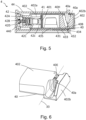
figure 6 est une vue en perspective du socle de lafigure 3 avec le corps plastique, - La
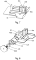
figure 7 est une vue en perspective du socle de lafigure 6 sans le corps plastique, - La
figure 8 est une vue en éclaté du mécanisme rétractable de lafigure 1 .
- There
figure 1 is a perspective view of a knife holder according to a particular embodiment of the invention, - There
figure 2 is a perspective view of a sharpening system of thefigure 1 , the base being in its storage position, - There
picture 3face 1
- There
figure 4 is a sectional view of the sharpening system, along section line IV-IV of thefigure 2 , - There
figure 5 is a sectional view of the sharpening system, along section line VV of thepicture 3 - There
figure 6 is a perspective view of the base of thepicture 3 - There
figure 7 is a perspective view of the base of thefigure 6 without the plastic body, - There
figure 8 is an exploded view of the retractable mechanism of thefigure 1 .
Le mode particulier de réalisation de la présente invention décrit ci-dessous concerne un support de couteaux, tel qu'un bloc-couteau, comportant un système d'affûtage d'une lame d'un des couteaux. Comme illustré à la
Le support 1 comporte un système d'affûtage 4 de la lame de couteaux qui est agencé sur une partie inférieure du support 1, en dessous du bâti 2. Tel qu'illustré à la
Conformément aux
En se référant aux
En plus, le mécanisme rétractable 42 comporte un élément magnétique 41 en forme de disque qui est agencé dans une cavité 42c cylindrique du piston 42C. Par élément magnétique, on comprend un aimant permanent qui peut exercer une force d'attraction sur tout matériau ferromagnétique. L'élément magnétique 41 peut être par exemple un aimant néodyme. Le socle 40 comporte une plaque ferromagnétique 401 qui est agencée verticalement sur une paroi de fond 435 du socle 40. L'élément magnétique 41 exerce une force d'attraction sur la plaque ferromagnétique 401 pour permettre de maintenir le socle 40 au piston 42C du mécanisme rétractable 42. Le socle 40 comporte un corps plastique 402. La plaque ferromagnétique 401 est agencée à l'intérieur du corps plastique 402. Le corps plastique 402 comporte une paroi intermédiaire 402a qui est disposée entre l'élément magnétique 41 et la plaque ferromagnétique 401 afin d'éviter un contact direct entre l'élément magnétique 41 et la plaque ferromagnétique 401. Ainsi, la plaque ferromagnétique 401 est protégée par le corps plastique 402 contre l'oxydation.In addition, the
Le piston 42C du mécanisme rétractable 42 est mobile en translation selon la direction transversale 11 entre une position entrée dans laquelle le socle 40 est dans sa position de rangement et une position sortie dans laquelle le socle 40 est dans sa position de préhension. Le socle 40 suit le mouvement en translation du piston 42C lorsque le socle 40 est maintenu au piston 42C par l'élément magnétique 41. Le mécanisme rétractable 42 permet de manoeuvrer rapidement le socle 40 entre sa position de rangement et sa position de préhension, en poussant simplement sur le corps plastique 402 du socle 40.The
Comme le montrent les
En se référant aux
De plus, Le système d'affûtage 4 comporte deux organes d'affûtage 40a qui sont installés sur le socle 40, les deux organes d'affûtage 40a étant solidaires du socle 40. Les deux organes d'affûtage 40a sous forme de cylindre sont réalisés en une matière très dure, par exemple en tungstène. Chaque organe d'affûtage 40a comporte une extrémité haute 40H et une extrémité basse 40B. Tel qu'illustrée aux
En fonctionnement, lorsque l'utilisateur souhaite effectuer une opération d'affûtage de la lame d'un couteau, il pousse d'abord avec son doigt selon la direction transversale 11 sur une surface externe 402b du corps plastique 402 du socle 40 en position de rangement. Sous l'action de l'utilisateur, le ressort 42D du mécanisme rétractable 42 est comprimé pour restituer une force de rappel sur le socle 40 pour entrainer une déformation de la lamelle 431 permettant à la protubérance 433 de passer au-dessous du bossage 434. Ainsi, le socle 40 quitte sa position de rangement vers sa position de préhension. Lorsque le socle 40 est arrivé à sa position de préhension dans laquelle le corps plastique 402 du socle 40 est partiellement sorti du bâti 2, l'utilisateur saisit une zone de préhension du corps plastique 402 qui est sortie du bâti 2 et tire l'ensemble du socle 40 afin de vaincre la force d'attraction de l'élément magnétique 41 pour permettre de séparer le socle 40 du support 1. Enfin, l'utilisateur peut porter le socle 40 comportant les organes d'affûtage 40a dans un endroit adapté, par exemple sur le bord d'un plan de travail pour effectuer une opération d'affûtage de la lame d'un couteau.In operation, when the user wishes to perform a sharpening operation of the blade of a knife, he first pushes with his finger in the
Une fois que l'opération d'affûtage est terminée, l'utilisateur saisit le socle 40 et l'approche vers sa position de préhension dans le bâti 2. Le socle 40 est ensuite attiré et maintenu au mécanisme rétractable 42 par l'élément magnétique 41. Puis, l'utilisateur pousse le socle 40 pour le faire passer de sa position de préhension dans sa position de rangement et la protubérance 433 de la lamelle 431 passe derrière le bossage 434 afin d'immobiliser le socle 40 dans sa position de rangement. En conséquence, le socle 40 est rangé dans le bâti 2.Once the sharpening operation is complete, the user grasps the
Bien entendu, l'invention n'est nullement limitée au mode de réalisation décrit et illustré qui n'a été donné qu'à titre d'exemple. Des modifications restent possibles, notamment du point de vue de la constitution des divers éléments ou par substitution d'équivalents techniques, sans sortir pour autant du domaine de protection de l'invention.Of course, the invention is in no way limited to the embodiment described and illustrated which has been given only by way of example. Modifications remain possible, in particular from the point of view of the constitution of the various elements or by substitution of technical equivalents, without departing from the scope of protection of the invention.
Dans une variante de réalisation, le maintien du socle au système d'affûtage peut être réalisé par deux éléments magnétiques qui s'attirent, dont l'un est solidaire du socle et l'autre est solidaire du mécanisme rétractable.In a variant embodiment, the holding of the base to the sharpening system can be achieved by two magnetic elements which attract each other, one of which is fixed to the base and the other is fixed to the retractable mechanism.
Dans une variante de réalisation, le socle est mobile en translation selon la direction d'extension verticale du bâti.In a variant embodiment, the base is movable in translation along the direction of vertical extension of the frame.
Claims (10)
- Knife holder (1) comprising- a casing (2),- a holding device (3) intended to receive knives, and- a sharpening system (4) intended to sharpen a blade of said knives, said sharpening system comprising a base (40) and at least one sharpening member (40a) which is integral with the base (40), the base (40) being movable with respect to the casing (2) between a storage position wherein the base (40) is inside the casing (2) and a gripping position wherein the base (40) partially exits from the casing (2),the base (40) being held to the sharpening system (4) by at least one magnetic element (41), characterised in that the base can be separated from the knife holder (1) without a physical link when it is in its gripping position to perform an operation of sharpening the blade.
- Knife holder (1) according to claim 1, characterised in that the base (40) is held to the sharpening system (4) by two magnetic elements or by a magnetic element (41) and a ferromagnetic element.
- Knife holder (1) according to any one of the preceding claims, characterised in that the base (40) is movable in translation with respect to the casing (2) between its storage position and its gripping position.
- Knife holder (1) according to claim 3, characterised in that the base (40) is movable in translation in a transverse direction (11) perpendicular to a vertical extension direction (22) of the casing (2).
- Knife holder (1) according to any one of the preceding claims, characterised in that the sharpening system (4) comprises a retractable mechanism (42) of the retractable ball pen type, a pressure applied on the base (40) in its storage position making it possible make it pass into its gripping position, and reciprocally.
- Knife holder (1) according to claim 5, characterised in that the retractable mechanism (42) comprises a stopper (42A), a cam (42B) and a piston (42C), the piston (42C) being movable in translation with respect to the casing (2) between a retracted position wherein the base (40) is in its storage position and an exit position wherein the base (40) is in its gripping position, the base (40) being held to the piston (42C) by the at least one magnetic element (41).
- Knife holder (1) according to claim 6, characterised in that the at least one magnetic element (41) is integral with the piston (42C), and in that the base (40) comprises a ferromagnetic plate (401), the at least one magnetic element (41) exerting an attraction force on the ferromagnetic plate (401) to hold the base (40) to the piston (42C).
- Knife holder (1) according to claim 7, characterised in that the base (40) comprises a plastic body (402), the ferromagnetic plate (401) being arranged inside the plastic body (402).
- Knife holder (1) according to any one of the preceding claims, characterised in that the sharpening system (4) comprises a device for holding (43) the base (40) in its storage position.
- Knife holder (1) according to claim 8, characterised in that the holding device (43) comprises a blade (431), a free end (432) of which is equipped with a projection (433) as well as a boss (434) disposed on a bottom wall (435) of the base (40), the projection (433) engaging with the boss (434) to make it possible to hold the base (40) in its storage position.
Applications Claiming Priority (1)
| Application Number | Priority Date | Filing Date | Title |
|---|---|---|---|
| FR1759857A FR3072550B1 (en) | 2017-10-19 | 2017-10-19 | KNIFE HOLDER WITH SHARPENING SYSTEM |
Publications (2)
| Publication Number | Publication Date |
|---|---|
| EP3473141A1 EP3473141A1 (en) | 2019-04-24 |
| EP3473141B1 true EP3473141B1 (en) | 2023-03-22 |
Family
ID=61003141
Family Applications (1)
| Application Number | Title | Priority Date | Filing Date |
|---|---|---|---|
| EP18200579.3A Active EP3473141B1 (en) | 2017-10-19 | 2018-10-16 | Knife holder with sharpening system |
Country Status (5)
| Country | Link |
|---|---|
| EP (1) | EP3473141B1 (en) |
| JP (1) | JP7325174B2 (en) |
| CN (2) | CN109691916A (en) |
| ES (1) | ES2942412T3 (en) |
| FR (1) | FR3072550B1 (en) |
Families Citing this family (5)
| Publication number | Priority date | Publication date | Assignee | Title |
|---|---|---|---|---|
| FR3072550B1 (en) * | 2017-10-19 | 2021-01-01 | Seb Sa | KNIFE HOLDER WITH SHARPENING SYSTEM |
| JP6704558B1 (en) | 2020-01-29 | 2020-06-03 | 株式会社貝印刃物開発センター | Cutlery storage |
| EP3884824B1 (en) | 2020-01-29 | 2022-03-23 | Kai R & D Center Co., Ltd. | Storage device set for edged tools |
| US11376713B1 (en) | 2021-03-09 | 2022-07-05 | Sharkninja Operating Llc | Knife sharpening systems |
| CN218500163U (en) * | 2022-09-21 | 2023-02-21 | V尼维斯有限责任公司 | Knife and fork storage box with knife sharpener |
Family Cites Families (10)
| Publication number | Priority date | Publication date | Assignee | Title |
|---|---|---|---|---|
| DE20319328U1 (en) * | 2003-12-12 | 2004-03-04 | Warimex Waren-Import-Export Handels Gmbh | Block used as a knife block comprises fixing points, recesses or holders allowing the insertion of other objects in addition to knives and/or tool sharpening steels |
| CN2862928Y (en) * | 2005-10-21 | 2007-01-31 | 曾令东 | A knife holder with a knife sharpener |
| US9149914B2 (en) * | 2012-05-10 | 2015-10-06 | Elemental Tools, Llc | Knife block systems |
| CN103519721B (en) | 2013-10-28 | 2015-07-01 | 无锡艾科瑞思产品设计与研究有限公司 | Combined knife rest with knife sharpener |
| CN104552040A (en) * | 2014-12-23 | 2015-04-29 | 中山市泰帝科技有限公司 | A multifunctional portable knife sharpener |
| CN204394348U (en) * | 2015-01-28 | 2015-06-17 | 瑞安市金裕铝业有限公司 | Multifunctional knife rack |
| CN205083336U (en) * | 2015-10-25 | 2016-03-16 | 石佳潼 | Can prevent unrestrained chopping board of vegetables |
| US9744649B2 (en) | 2016-01-07 | 2017-08-29 | Richard A. Williams | SUB (sound utility block) |
| FR3072550B1 (en) * | 2017-10-19 | 2021-01-01 | Seb Sa | KNIFE HOLDER WITH SHARPENING SYSTEM |
| CN210697069U (en) | 2019-11-12 | 2020-06-09 | 北京林业大学 | Tool apron and tool combination |
-
2017
- 2017-10-19 FR FR1759857A patent/FR3072550B1/en active Active
-
2018
- 2018-10-15 JP JP2018194518A patent/JP7325174B2/en active Active
- 2018-10-16 ES ES18200579T patent/ES2942412T3/en active Active
- 2018-10-16 EP EP18200579.3A patent/EP3473141B1/en active Active
- 2018-10-19 CN CN201811221854.7A patent/CN109691916A/en active Pending
- 2018-10-19 CN CN201821700589.6U patent/CN209518793U/en active Active
Also Published As
| Publication number | Publication date |
|---|---|
| ES2942412T3 (en) | 2023-06-01 |
| EP3473141A1 (en) | 2019-04-24 |
| JP2019077030A (en) | 2019-05-23 |
| FR3072550B1 (en) | 2021-01-01 |
| FR3072550A1 (en) | 2019-04-26 |
| CN209518793U (en) | 2019-10-22 |
| CN109691916A (en) | 2019-04-30 |
| JP7325174B2 (en) | 2023-08-14 |
Similar Documents
| Publication | Publication Date | Title |
|---|---|---|
| EP3473141B1 (en) | Knife holder with sharpening system | |
| EP1273399B1 (en) | Cutting device with retractable blade | |
| FR2929354A1 (en) | LATCHING DEVICE FOR TELESCOPIC ROD AND APPARATUS PROVIDED WITH SUCH A LOCKING DEVICE | |
| WO2014029949A1 (en) | Removable attachment device for attaching to longer linear or filiform objects | |
| EP4135930A1 (en) | Sharpening sheath adapted to receive a knife, and combination of such a sheath and a knife | |
| WO2013114018A1 (en) | Writing instrument having a protective element for the retractable tip | |
| EP2493661B1 (en) | Device for holding a hand tool and kit including such a device | |
| FR3058136A1 (en) | CAPPER WITH DOUBLE LEVER. | |
| EP3728059B1 (en) | Bottle provided with a locking device in the closure | |
| FR2643022A1 (en) | DEVICE FOR USE WITH REMOVABLE SELF-ADHESIVE LABELS | |
| EP0468899B1 (en) | System to detachably connect a part to a fixed member, said part being in particular a wheel-cover | |
| WO2021209196A1 (en) | Combination of a sheath and a knife | |
| FR3006642A1 (en) | MECHANISM FOR MAINTAINING A PLANAR OBJECT IN THE BACK OF A SEAT OF A MOTOR VEHICLE | |
| EP1712434A1 (en) | Retractable schock absorbing stop for motor vehicle | |
| MC1028A1 (en) | Pen or similar object, with retractable clip | |
| FR2925422A1 (en) | Object e.g. bottle, maintaining device for e.g. lateral door of motor vehicle, has strip with free end such that end passes from rest position in which strip is plated against wall to usage position in which strip is plated against object | |
| FR2726217A1 (en) | Trimming and cleaning tool for vehicle windscreen | |
| WO2021209195A1 (en) | Sharpening sheath adapted to receive a knife, and combination of such a sheath and a knife | |
| FR2666268A1 (en) | Cutting-out knife with retractable blade | |
| FR3012567A1 (en) | LATCHING SYSTEM OF SUPPORT FOR APPARATUS APPARATUS ADJUSTABLE AT HEIGHT | |
| FR3058350A1 (en) | CUTTER WITH A ROULETTE TO CONTROL CUTTING PRESSURE | |
| FR3072316A1 (en) | TOOL EQUIPPED WITH A BLOCKING DEVICE IN AT LEAST ONE POSITION OF A MOBILE PART OF THE TOOL | |
| FR2801239A1 (en) | Windscreen scraper for vehicle has a palm fit grip with a slider to hold a replaceable thin blade | |
| EP0725707B1 (en) | Exceptionally flat hand tool for polishing or deburring | |
| EP1798008B1 (en) | Pocket knife with a nailclipper |
Legal Events
| Date | Code | Title | Description |
|---|---|---|---|
| PUAI | Public reference made under article 153(3) epc to a published international application that has entered the european phase |
Free format text: ORIGINAL CODE: 0009012 |
|
| STAA | Information on the status of an ep patent application or granted ep patent |
Free format text: STATUS: THE APPLICATION HAS BEEN PUBLISHED |
|
| AK | Designated contracting states |
Kind code of ref document: A1 Designated state(s): AL AT BE BG CH CY CZ DE DK EE ES FI FR GB GR HR HU IE IS IT LI LT LU LV MC MK MT NL NO PL PT RO RS SE SI SK SM TR |
|
| AX | Request for extension of the european patent |
Extension state: BA ME |
|
| STAA | Information on the status of an ep patent application or granted ep patent |
Free format text: STATUS: REQUEST FOR EXAMINATION WAS MADE |
|
| 17P | Request for examination filed |
Effective date: 20191018 |
|
| RBV | Designated contracting states (corrected) |
Designated state(s): AL AT BE BG CH CY CZ DE DK EE ES FI FR GB GR HR HU IE IS IT LI LT LU LV MC MK MT NL NO PL PT RO RS SE SI SK SM TR |
|
| STAA | Information on the status of an ep patent application or granted ep patent |
Free format text: STATUS: EXAMINATION IS IN PROGRESS |
|
| 17Q | First examination report despatched |
Effective date: 20210426 |
|
| GRAP | Despatch of communication of intention to grant a patent |
Free format text: ORIGINAL CODE: EPIDOSNIGR1 |
|
| STAA | Information on the status of an ep patent application or granted ep patent |
Free format text: STATUS: GRANT OF PATENT IS INTENDED |
|
| INTG | Intention to grant announced |
Effective date: 20221020 |
|
| GRAS | Grant fee paid |
Free format text: ORIGINAL CODE: EPIDOSNIGR3 |
|
| GRAA | (expected) grant |
Free format text: ORIGINAL CODE: 0009210 |
|
| STAA | Information on the status of an ep patent application or granted ep patent |
Free format text: STATUS: THE PATENT HAS BEEN GRANTED |
|
| AK | Designated contracting states |
Kind code of ref document: B1 Designated state(s): AL AT BE BG CH CY CZ DE DK EE ES FI FR GB GR HR HU IE IS IT LI LT LU LV MC MK MT NL NO PL PT RO RS SE SI SK SM TR |
|
| REG | Reference to a national code |
Ref country code: GB Ref legal event code: FG4D Free format text: NOT ENGLISH |
|
| REG | Reference to a national code |
Ref country code: CH Ref legal event code: EP |
|
| REG | Reference to a national code |
Ref country code: IE Ref legal event code: FG4D Free format text: LANGUAGE OF EP DOCUMENT: FRENCH |
|
| REG | Reference to a national code |
Ref country code: DE Ref legal event code: R096 Ref document number: 602018047432 Country of ref document: DE |
|
| REG | Reference to a national code |
Ref country code: AT Ref legal event code: REF Ref document number: 1554771 Country of ref document: AT Kind code of ref document: T Effective date: 20230415 |
|
| REG | Reference to a national code |
Ref country code: ES Ref legal event code: FG2A Ref document number: 2942412 Country of ref document: ES Kind code of ref document: T3 Effective date: 20230601 |
|
| REG | Reference to a national code |
Ref country code: LT Ref legal event code: MG9D |
|
| REG | Reference to a national code |
Ref country code: NL Ref legal event code: MP Effective date: 20230322 |
|
| PG25 | Lapsed in a contracting state [announced via postgrant information from national office to epo] |
Ref country code: RS Free format text: LAPSE BECAUSE OF FAILURE TO SUBMIT A TRANSLATION OF THE DESCRIPTION OR TO PAY THE FEE WITHIN THE PRESCRIBED TIME-LIMIT Effective date: 20230322 Ref country code: NO Free format text: LAPSE BECAUSE OF FAILURE TO SUBMIT A TRANSLATION OF THE DESCRIPTION OR TO PAY THE FEE WITHIN THE PRESCRIBED TIME-LIMIT Effective date: 20230622 Ref country code: LV Free format text: LAPSE BECAUSE OF FAILURE TO SUBMIT A TRANSLATION OF THE DESCRIPTION OR TO PAY THE FEE WITHIN THE PRESCRIBED TIME-LIMIT Effective date: 20230322 Ref country code: LT Free format text: LAPSE BECAUSE OF FAILURE TO SUBMIT A TRANSLATION OF THE DESCRIPTION OR TO PAY THE FEE WITHIN THE PRESCRIBED TIME-LIMIT Effective date: 20230322 Ref country code: HR Free format text: LAPSE BECAUSE OF FAILURE TO SUBMIT A TRANSLATION OF THE DESCRIPTION OR TO PAY THE FEE WITHIN THE PRESCRIBED TIME-LIMIT Effective date: 20230322 |
|
| REG | Reference to a national code |
Ref country code: AT Ref legal event code: MK05 Ref document number: 1554771 Country of ref document: AT Kind code of ref document: T Effective date: 20230322 |
|
| PG25 | Lapsed in a contracting state [announced via postgrant information from national office to epo] |
Ref country code: SE Free format text: LAPSE BECAUSE OF FAILURE TO SUBMIT A TRANSLATION OF THE DESCRIPTION OR TO PAY THE FEE WITHIN THE PRESCRIBED TIME-LIMIT Effective date: 20230322 Ref country code: NL Free format text: LAPSE BECAUSE OF FAILURE TO SUBMIT A TRANSLATION OF THE DESCRIPTION OR TO PAY THE FEE WITHIN THE PRESCRIBED TIME-LIMIT Effective date: 20230322 Ref country code: GR Free format text: LAPSE BECAUSE OF FAILURE TO SUBMIT A TRANSLATION OF THE DESCRIPTION OR TO PAY THE FEE WITHIN THE PRESCRIBED TIME-LIMIT Effective date: 20230623 Ref country code: FI Free format text: LAPSE BECAUSE OF FAILURE TO SUBMIT A TRANSLATION OF THE DESCRIPTION OR TO PAY THE FEE WITHIN THE PRESCRIBED TIME-LIMIT Effective date: 20230322 |
|
| PG25 | Lapsed in a contracting state [announced via postgrant information from national office to epo] |
Ref country code: SM Free format text: LAPSE BECAUSE OF FAILURE TO SUBMIT A TRANSLATION OF THE DESCRIPTION OR TO PAY THE FEE WITHIN THE PRESCRIBED TIME-LIMIT Effective date: 20230322 Ref country code: RO Free format text: LAPSE BECAUSE OF FAILURE TO SUBMIT A TRANSLATION OF THE DESCRIPTION OR TO PAY THE FEE WITHIN THE PRESCRIBED TIME-LIMIT Effective date: 20230322 Ref country code: PT Free format text: LAPSE BECAUSE OF FAILURE TO SUBMIT A TRANSLATION OF THE DESCRIPTION OR TO PAY THE FEE WITHIN THE PRESCRIBED TIME-LIMIT Effective date: 20230724 Ref country code: EE Free format text: LAPSE BECAUSE OF FAILURE TO SUBMIT A TRANSLATION OF THE DESCRIPTION OR TO PAY THE FEE WITHIN THE PRESCRIBED TIME-LIMIT Effective date: 20230322 Ref country code: AT Free format text: LAPSE BECAUSE OF FAILURE TO SUBMIT A TRANSLATION OF THE DESCRIPTION OR TO PAY THE FEE WITHIN THE PRESCRIBED TIME-LIMIT Effective date: 20230322 |
|
| PG25 | Lapsed in a contracting state [announced via postgrant information from national office to epo] |
Ref country code: SK Free format text: LAPSE BECAUSE OF FAILURE TO SUBMIT A TRANSLATION OF THE DESCRIPTION OR TO PAY THE FEE WITHIN THE PRESCRIBED TIME-LIMIT Effective date: 20230322 Ref country code: PL Free format text: LAPSE BECAUSE OF FAILURE TO SUBMIT A TRANSLATION OF THE DESCRIPTION OR TO PAY THE FEE WITHIN THE PRESCRIBED TIME-LIMIT Effective date: 20230322 Ref country code: IS Free format text: LAPSE BECAUSE OF FAILURE TO SUBMIT A TRANSLATION OF THE DESCRIPTION OR TO PAY THE FEE WITHIN THE PRESCRIBED TIME-LIMIT Effective date: 20230722 |
|
| REG | Reference to a national code |
Ref country code: DE Ref legal event code: R097 Ref document number: 602018047432 Country of ref document: DE |
|
| PLBE | No opposition filed within time limit |
Free format text: ORIGINAL CODE: 0009261 |
|
| STAA | Information on the status of an ep patent application or granted ep patent |
Free format text: STATUS: NO OPPOSITION FILED WITHIN TIME LIMIT |
|
| PG25 | Lapsed in a contracting state [announced via postgrant information from national office to epo] |
Ref country code: SI Free format text: LAPSE BECAUSE OF FAILURE TO SUBMIT A TRANSLATION OF THE DESCRIPTION OR TO PAY THE FEE WITHIN THE PRESCRIBED TIME-LIMIT Effective date: 20230322 Ref country code: DK Free format text: LAPSE BECAUSE OF FAILURE TO SUBMIT A TRANSLATION OF THE DESCRIPTION OR TO PAY THE FEE WITHIN THE PRESCRIBED TIME-LIMIT Effective date: 20230322 Ref country code: CZ Free format text: LAPSE BECAUSE OF FAILURE TO SUBMIT A TRANSLATION OF THE DESCRIPTION OR TO PAY THE FEE WITHIN THE PRESCRIBED TIME-LIMIT Effective date: 20230322 |
|
| 26N | No opposition filed |
Effective date: 20240102 |
|
| PG25 | Lapsed in a contracting state [announced via postgrant information from national office to epo] |
Ref country code: IT Free format text: LAPSE BECAUSE OF FAILURE TO SUBMIT A TRANSLATION OF THE DESCRIPTION OR TO PAY THE FEE WITHIN THE PRESCRIBED TIME-LIMIT Effective date: 20230322 Ref country code: MC Free format text: LAPSE BECAUSE OF FAILURE TO SUBMIT A TRANSLATION OF THE DESCRIPTION OR TO PAY THE FEE WITHIN THE PRESCRIBED TIME-LIMIT Effective date: 20230322 |
|
| REG | Reference to a national code |
Ref country code: CH Ref legal event code: PL |
|
| PG25 | Lapsed in a contracting state [announced via postgrant information from national office to epo] |
Ref country code: LU Free format text: LAPSE BECAUSE OF NON-PAYMENT OF DUE FEES Effective date: 20231016 |
|
| PG25 | Lapsed in a contracting state [announced via postgrant information from national office to epo] |
Ref country code: LU Free format text: LAPSE BECAUSE OF NON-PAYMENT OF DUE FEES Effective date: 20231016 |
|
| PG25 | Lapsed in a contracting state [announced via postgrant information from national office to epo] |
Ref country code: CH Free format text: LAPSE BECAUSE OF NON-PAYMENT OF DUE FEES Effective date: 20231031 |
|
| PG25 | Lapsed in a contracting state [announced via postgrant information from national office to epo] |
Ref country code: CH Free format text: LAPSE BECAUSE OF NON-PAYMENT OF DUE FEES Effective date: 20231031 |
|
| PG25 | Lapsed in a contracting state [announced via postgrant information from national office to epo] |
Ref country code: IE Free format text: LAPSE BECAUSE OF NON-PAYMENT OF DUE FEES Effective date: 20231016 |
|
| PG25 | Lapsed in a contracting state [announced via postgrant information from national office to epo] |
Ref country code: IE Free format text: LAPSE BECAUSE OF NON-PAYMENT OF DUE FEES Effective date: 20231016 |
|
| PG25 | Lapsed in a contracting state [announced via postgrant information from national office to epo] |
Ref country code: BG Free format text: LAPSE BECAUSE OF FAILURE TO SUBMIT A TRANSLATION OF THE DESCRIPTION OR TO PAY THE FEE WITHIN THE PRESCRIBED TIME-LIMIT Effective date: 20230322 |
|
| PG25 | Lapsed in a contracting state [announced via postgrant information from national office to epo] |
Ref country code: BG Free format text: LAPSE BECAUSE OF FAILURE TO SUBMIT A TRANSLATION OF THE DESCRIPTION OR TO PAY THE FEE WITHIN THE PRESCRIBED TIME-LIMIT Effective date: 20230322 |
|
| PGFP | Annual fee paid to national office [announced via postgrant information from national office to epo] |
Ref country code: DE Payment date: 20241010 Year of fee payment: 7 |
|
| PGFP | Annual fee paid to national office [announced via postgrant information from national office to epo] |
Ref country code: BE Payment date: 20241016 Year of fee payment: 7 |
|
| PGFP | Annual fee paid to national office [announced via postgrant information from national office to epo] |
Ref country code: GB Payment date: 20241028 Year of fee payment: 7 |
|
| PGFP | Annual fee paid to national office [announced via postgrant information from national office to epo] |
Ref country code: FR Payment date: 20241024 Year of fee payment: 7 |
|
| PGFP | Annual fee paid to national office [announced via postgrant information from national office to epo] |
Ref country code: ES Payment date: 20241108 Year of fee payment: 7 |
|
| PG25 | Lapsed in a contracting state [announced via postgrant information from national office to epo] |
Ref country code: CY Free format text: LAPSE BECAUSE OF FAILURE TO SUBMIT A TRANSLATION OF THE DESCRIPTION OR TO PAY THE FEE WITHIN THE PRESCRIBED TIME-LIMIT; INVALID AB INITIO Effective date: 20181016 |
|
| PG25 | Lapsed in a contracting state [announced via postgrant information from national office to epo] |
Ref country code: HU Free format text: LAPSE BECAUSE OF FAILURE TO SUBMIT A TRANSLATION OF THE DESCRIPTION OR TO PAY THE FEE WITHIN THE PRESCRIBED TIME-LIMIT; INVALID AB INITIO Effective date: 20181016 |
|
| PG25 | Lapsed in a contracting state [announced via postgrant information from national office to epo] |
Ref country code: TR Free format text: LAPSE BECAUSE OF FAILURE TO SUBMIT A TRANSLATION OF THE DESCRIPTION OR TO PAY THE FEE WITHIN THE PRESCRIBED TIME-LIMIT Effective date: 20230322 |