EP3473183A1 - Dispositif d'imagerie par rayonnement - Google Patents
Dispositif d'imagerie par rayonnement Download PDFInfo
- Publication number
- EP3473183A1 EP3473183A1 EP17812955.7A EP17812955A EP3473183A1 EP 3473183 A1 EP3473183 A1 EP 3473183A1 EP 17812955 A EP17812955 A EP 17812955A EP 3473183 A1 EP3473183 A1 EP 3473183A1
- Authority
- EP
- European Patent Office
- Prior art keywords
- image
- grating
- absorption
- self
- radiation
- Prior art date
- Legal status (The legal status is an assumption and is not a legal conclusion. Google has not performed a legal analysis and makes no representation as to the accuracy of the status listed.)
- Withdrawn
Links
Images











Classifications
-
- G—PHYSICS
- G01—MEASURING; TESTING
- G01N—INVESTIGATING OR ANALYSING MATERIALS BY DETERMINING THEIR CHEMICAL OR PHYSICAL PROPERTIES
- G01N23/00—Investigating or analysing materials by the use of wave or particle radiation, e.g. X-rays or neutrons, not covered by groups G01N3/00 – G01N17/00, G01N21/00 or G01N22/00
- G01N23/02—Investigating or analysing materials by the use of wave or particle radiation, e.g. X-rays or neutrons, not covered by groups G01N3/00 – G01N17/00, G01N21/00 or G01N22/00 by transmitting the radiation through the material
- G01N23/04—Investigating or analysing materials by the use of wave or particle radiation, e.g. X-rays or neutrons, not covered by groups G01N3/00 – G01N17/00, G01N21/00 or G01N22/00 by transmitting the radiation through the material and forming images of the material
- G01N23/041—Phase-contrast imaging, e.g. using grating interferometers
-
- A—HUMAN NECESSITIES
- A61—MEDICAL OR VETERINARY SCIENCE; HYGIENE
- A61B—DIAGNOSIS; SURGERY; IDENTIFICATION
- A61B6/00—Apparatus or devices for radiation diagnosis; Apparatus or devices for radiation diagnosis combined with radiation therapy equipment
-
- A—HUMAN NECESSITIES
- A61—MEDICAL OR VETERINARY SCIENCE; HYGIENE
- A61B—DIAGNOSIS; SURGERY; IDENTIFICATION
- A61B6/00—Apparatus or devices for radiation diagnosis; Apparatus or devices for radiation diagnosis combined with radiation therapy equipment
- A61B6/42—Arrangements for detecting radiation specially adapted for radiation diagnosis
- A61B6/4291—Arrangements for detecting radiation specially adapted for radiation diagnosis the detector being combined with a grid or grating
-
- A—HUMAN NECESSITIES
- A61—MEDICAL OR VETERINARY SCIENCE; HYGIENE
- A61B—DIAGNOSIS; SURGERY; IDENTIFICATION
- A61B6/00—Apparatus or devices for radiation diagnosis; Apparatus or devices for radiation diagnosis combined with radiation therapy equipment
- A61B6/48—Diagnostic techniques
- A61B6/484—Diagnostic techniques involving phase contrast X-ray imaging
-
- G—PHYSICS
- G01—MEASURING; TESTING
- G01N—INVESTIGATING OR ANALYSING MATERIALS BY DETERMINING THEIR CHEMICAL OR PHYSICAL PROPERTIES
- G01N23/00—Investigating or analysing materials by the use of wave or particle radiation, e.g. X-rays or neutrons, not covered by groups G01N3/00 – G01N17/00, G01N21/00 or G01N22/00
- G01N23/02—Investigating or analysing materials by the use of wave or particle radiation, e.g. X-rays or neutrons, not covered by groups G01N3/00 – G01N17/00, G01N21/00 or G01N22/00 by transmitting the radiation through the material
- G01N23/04—Investigating or analysing materials by the use of wave or particle radiation, e.g. X-rays or neutrons, not covered by groups G01N3/00 – G01N17/00, G01N21/00 or G01N22/00 by transmitting the radiation through the material and forming images of the material
- G01N23/046—Investigating or analysing materials by the use of wave or particle radiation, e.g. X-rays or neutrons, not covered by groups G01N3/00 – G01N17/00, G01N21/00 or G01N22/00 by transmitting the radiation through the material and forming images of the material using tomography, e.g. computed tomography [CT]
-
- G—PHYSICS
- G01—MEASURING; TESTING
- G01N—INVESTIGATING OR ANALYSING MATERIALS BY DETERMINING THEIR CHEMICAL OR PHYSICAL PROPERTIES
- G01N2223/00—Investigating materials by wave or particle radiation
- G01N2223/30—Accessories, mechanical or electrical features
- G01N2223/303—Accessories, mechanical or electrical features calibrating, standardising
-
- G—PHYSICS
- G01—MEASURING; TESTING
- G01N—INVESTIGATING OR ANALYSING MATERIALS BY DETERMINING THEIR CHEMICAL OR PHYSICAL PROPERTIES
- G01N2223/00—Investigating materials by wave or particle radiation
- G01N2223/60—Specific applications or type of materials
- G01N2223/612—Specific applications or type of materials biological material
- G01N2223/6126—Specific applications or type of materials biological material tissue
-
- G—PHYSICS
- G01—MEASURING; TESTING
- G01N—INVESTIGATING OR ANALYSING MATERIALS BY DETERMINING THEIR CHEMICAL OR PHYSICAL PROPERTIES
- G01N23/00—Investigating or analysing materials by the use of wave or particle radiation, e.g. X-rays or neutrons, not covered by groups G01N3/00 – G01N17/00, G01N21/00 or G01N22/00
- G01N23/02—Investigating or analysing materials by the use of wave or particle radiation, e.g. X-rays or neutrons, not covered by groups G01N3/00 – G01N17/00, G01N21/00 or G01N22/00 by transmitting the radiation through the material
- G01N23/04—Investigating or analysing materials by the use of wave or particle radiation, e.g. X-rays or neutrons, not covered by groups G01N3/00 – G01N17/00, G01N21/00 or G01N22/00 by transmitting the radiation through the material and forming images of the material
- G01N23/044—Investigating or analysing materials by the use of wave or particle radiation, e.g. X-rays or neutrons, not covered by groups G01N3/00 – G01N17/00, G01N21/00 or G01N22/00 by transmitting the radiation through the material and forming images of the material using laminography or tomosynthesis
Definitions
- the present invention relates to a radiation imaging apparatus capable of imaging an internal structure of an object by utilizing radiation transmitted through the object.
- a commonly-used radiation imaging apparatus is configured to capture a radiation projection image by irradiating radiation to an object to make the radiation transmit through the object.
- the contrasting density appears depending on the ease of permeation of radiation, which represents the internal structure of the object.
- a radiation phase contrast imaging device that images an internal structure of an object by utilizing a phase contrast of transmitted radiation.
- Such a device is configured to image an internal structure of an object using Talbot interference.
- phase-aligned radiation is irradiated.
- the image of the phase grating 55 appears on the projection plane which is apart from the phase grating 55 by a predetermined distance (Talbot distance).
- This image is called a self-image.
- this self-image is not just a projection image of the phase grating 55.
- the self-image occurs only at the position where the projection plane is separated from the phase grating 55 by the Talbot distance.
- the self-image is configured by the interference fringes caused by interference of light.
- the reason that the self-image of the phase grating 55 appears at the Talbot distance is that the phase of radiation generated from the radiation source 53 is aligned. When the phase of radiation is disturbed, the self-image appearing at the Talbot distance is also disturbed.
- the radiation phase contrast imaging device is configured to image an internal structure of an object by utilizing the self-image disturbance. It is assumed that an object is placed between the radiation source and the phase grating 55. Since this object hardly absorbs radiation, most of the radiation incident on the object exits to the phase grating 55 side.
- the radiation has not passed through the object completely as it is. The reason is that the phase of the radiation changes while passing through the object.
- the radiation exited the object passes through the phase grating 55 with the phase changed.
- the observation of the radiation on the projection plane arranged at the Talbot distance shows disturbances in the self-image of the phase grating 55.
- the degree of disturbances of this self-image represents the radiation phase change.
- the specific magnitude of the phase change of the radiation transmitted the object changes depends on where the radiation passed through the object. If the object has a homogeneous configuration, the change of the radiation phase remains the same no matter where the radiation transmits through the object. In general, however, an object has some internal structure. When radiation is made to transmit such an object, the phase change does not remain the same.
- the internal structure of the object can be grasped.
- the phase change can be known by observing the self-image of the phase grating 55 at the Talbot distance.
- the detection of such a self-image is performed by a radiation detector.
- the radiation detector has a detection surface that detects radiation. By projecting a self-image on this detection surface, the radiation detector can perform imaging of the self-image (see, for example, Patent Document 1).
- the state of interference changes according to the change of the positional relationship. Based on the plural interference images thus obtained, it is possible to grasp the original self-image.
- To change the positional relationship between the self-image and the absorption grating it is realized by relatively moving the radiation source, the phase grating, and the absorption grating.
- the method of imaging using the interference between the radiation beam of a stripe pattern and the absorption grating of a stripe pattern is not limited to the imaging related to the Talbot interference. Even in the case of imaging using edge illumination, it uses interference between the radiation beam of a stripe pattern and an absorption grating of a stripe pattern. Further, a method of directly detecting a self-image in the absence of an absorption grating has been proposed. Further, as described in Talbot interference, a method of imaging with a plurality of fan beams or pencil beams by replacing a phase grating with a mask grid has also been proposed.
- Patent Document 1 International Patent Publication No. 2012/056724
- the conventional radiation phase contrast imaging device has the following problems.
- a self-image cannot be captured directly.
- a self-image is reconstructed by computation.
- the processing is executed on the premise that each of the interference images is captured when the self-image and the absorption grating become a predetermined positional relationship. It is possible to predict that each of the interference images will become what kind of images before image capturing. However, the actually obtained interference image is different from the predicted image since the subject is reflected. The difference from this prediction represents the internal structure of the subject.
- the self-image and the absorption grating have fine stripe patterns.
- the capturing of the interference image must be performed when the self-image and the absorption grating are in specific positions. However, it is difficult to make the positional relationship between the self-image and the absorption grating ideal.
- the image capturing of the interference image is performed in a state in which the self-image and the absorption grating have a positional relationship deviated from the ideal positional relationship. In such a case, the arithmetic processing related to the reconstruction of the self-image is not operated properly, which in turn generates a self-image different from the actual.
- imaging before imaging a subject, imaging must be performed in the absence of a subject. It takes time and effort to perform the imaging. Such a problem becomes serious, especially when performing CT imaging.
- CT imaging tomographic images of an internal structure of a subject are captured by repeatedly capturing the self-image while rotating the subject.
- the number of the interference images becomes considerably large, and therefore it takes time for the imaging. So, the positional relationship of the grating changes during the imaging. For this reason, even if the continuous imaging in the absence of a subject is performed and then the positional relationship of the gratings is calculated before CT imaging, it could happen that the self-image obtained at the end of the imaging is far apart from the self-image of the calculated grating position.
- the present invention has been made in view of the aforementioned circumstances, and an object of the present invention is to provide a radiation imaging apparatus capable of performing precise imaging without performing pre-imaging in the absence of a subject immediately before.
- the present invention has the following configuration.
- the radiation imaging method according to the present invention includes:
- the apparatus of the present invention is provided with a grating provided with a subject area and a reference area. Both areas each have a predetermined pattern that absorbs radiation, but the patterns are different from each other.
- the image of the grating (grating image) focused on the detection surface is captured with a detection element provided so as to cover the detection surface.
- the change in the relative position between the grating and the detection surface which is equal to or less than the pitch / integer multiple of the detection element is more difficult to detect than in the subject area image.
- the integer multiple is about 2 to 8
- the change in the relative position which is difficult to detect becomes a large error factor.
- a reference area having a pattern different from that of the subject area is provided. In this area, an image of the grating is observed in a moire pattern of a long period.
- This moire-like image of a long period is changed by the minute change of the relative position between the grating and the detection surface, so it is possible to detect minute changes of the relative position of the radiation source, the grating, and the detection surface from the image of the reference area. Even if the subject appears in the reference area, it is possible to detect the change in the relative position by averaging the direction in which the grating absorption extends, but it is preferable that there is no subject in the reference area.
- the same effects can be obtained by providing the reference areas having a different pitch in the detection surface, instead of providing a reference area to the grating.
- the relative position among the radiation source, the grating, and the detection surface can be accurately known. By correcting it, it becomes possible to improve the imaging spatial resolution of the subject arranged near the grating.
- the radiation imaging apparatus includes:
- the present invention can also be applied to a configuration having no absorption grating. That is, in the present invention, the moire generated between the image of the pattern of the reference area appearing on the detection surface and the array of each detection element can be used to find the relative position between the grating and the detection surface.
- the reference area of the grating be provided at an end portion of the subject area in one direction.
- the reference area of the grating be provided at both end portions of the subject area in one direction.
- the positional displacement of the grating in the rotational direction can also be detected by providing the reference area at both ends.
- the pattern in the reference area be configured by arranging dark lines for absorbing radiation
- the pattern in the absorption grating be configured by arranging dark lines for absorbing radiation
- an array pitch of the dark lines in the reference area be not an integer multiple of an array pitch of the dark lines in the absorption grating.
- a pattern in the reference area be configured by arranging dark lines for absorbing radiation, and an array pitch of the dark lines be not an integer multiple of an array pitch of the detection element.
- the pattern in the subject area of the grating be for a moire single imaging method.
- the present invention can also be applied to imaging using a moire single imaging method.
- a plurality of images be added based on the relative position calculated by the position calculation unit.
- the apparatus of the present invention is provided with a grating provided with a subject area and a reference area. Both areas each have a predetermined pattern that absorbs radiation, but both the patterns are different from each other. In this area, the image of the grating is observed in a moire pattern of a long period. The position of the moire-like image of this long period changes by the minute change of the relative position between the grating and the detection surface, so it becomes possible to detect minute changes of the relative position of the radiation source, the grating, and the detection surface from the image of the reference area.
- X-rays correspond to the radiation of the present invention.
- An FPD is an abbreviation of a flat panel detector.
- an image of a phase grating which appears on a detection surface where X-rays are incident is a self-image of the phase grating caused by Talbot interference.
- FIG. 1 is a functional block diagram illustrating the configuration of an X-ray phase contrast imaging apparatus according to the present invention.
- the X-ray source 3 according to the present invention is provided with a positive electrode 3a on which electrons collide and a multi-slit 3b on which X-rays irradiated from the positive electrode 3a are incident, and is configured to irradiate X-rays.
- the positive electrode 3a is a target of electrons, and X-rays are generated when a fast electron collides against the positive electrode. X-rays are generated at a single focal point.
- the X-ray source 3 irradiates X-rays.
- the X-ray source 3 is configured to output X-rays having a specific wavelength.
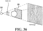
- a subject M is placed between the phase grating 5 and the FPD 4. Note that, as shown in FIG. 36 , it may be configured such that the subject M is placed between the multi-slit 3b and the phase grating 5.
- the X-ray source 3 corresponds to the radiation source of the present invention.
- the FPD 4 corresponds to the detection unit of the present invention
- the phase grating 5 corresponds to the grating of the present invention.
- the fan-shaped X-ray beam emitted from the positive electrode 3a is incident on the multi-slit 3b.
- the multi-slit 3b is made of a material, such as, e.g., gold, which is easy to be processed, and has a thickness to the extent that X-rays are not transmitted.
- the multi-slit 3b is configured such that slits extending in the vertical direction are arranged in the lateral direction. Each of the slits is a through-hole of the multi-slit 3b.
- slits that allow transmission of radiation generated at a single generation point are arranged at a constant pitch in a direction orthogonal to the extending direction of the slit, and X-rays incident on portions where no slits S are provided are absorbed.
- the X-ray beam generated at the positive electrode 3a passes through one of the slits provided in the multi-slit 3b and exits from the multi-slit 3b. At this time, each of the X-ray beams that have passed through the slits of the multi-slit 3b interferes, turns into an X-ray beam with high coherency, and goes toward the phase grating 5 (see FIG. 1 ).
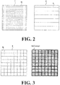
- the left side of FIG. 2 shows the phase grating 5.
- the phase grating 5 has a plurality of absorption lines 5a which absorb X-rays and extend in a linear shape.
- the absorption lines 5a are arranged in a vertical direction at a predetermined pitch in a direction perpendicular to the extending direction (lateral direction).
- the X-ray beam emitted from the multi-slit 3b passes through the phase grating 5. At that time, a part of the X-ray beam is absorbed by the phase grating 5.
- the X-ray beam emitted from the phase grating 5 has a pattern in which a plurality of bright lines remained without being absorbed by the absorption lines 5a is reflected.
- the X-rays emitted from the phase grating 5 are directed to the FPD 4 (see FIG. 1 ).
- the FPD 4 is configured to detect a self-image of the phase grating 5 caused by the Talbot interference at a detection surface 4a for detecting X-rays.
- the FPD 4 is, for example, a direct conversion type X-ray detector. That is, the FPD 4 has a conversion layer for converting X-rays into electrons and a hole pair (charge carrier pair). The carriers generated in the conversion layer are captured by and accumulated in each of the detection elements 4p. When a signal for outputting a carrier is sent to the detection element 4p, the detection element 4p outputs the accumulated carriers as a detection signal.
- the fineness of this detection element 4p is a main factor determining the spatial resolution of the FPD 4. The smaller the detection element 4p, the better the spatial resolution of the FPD 4, so that it is possible to detect a finer structure.
- the conversion layer corresponds to the conversion portion of the present invention.
- the FPD 4 according to Example 1 may be configured to detect fluorescence caused by X-rays.
- the FPD 4 has a configuration in which the image of the phase grating 5 is projected onto the detection surface 4a in which detection elements 4p for detecting X-rays are arranged in a matrix and the image of the phase grating 5 is detected.
- the absorption grating 6 is provided so as to cover the detection surface 4a on the FPD 4.
- the absorption grating 6 has a plurality of absorption lines 6a which absorb X-rays and extend in a linear shape.
- the absorption lines 6a are arranged at a predetermined pitch in a direction perpendicular to the extending direction.
- the pattern of this absorption line 6a of the stripe pattern and the pattern of the phase grating 5 of the stripe pattern interfere with each other. The state of this interference is detected by the FPD 4.
- an elongated absorption line 6a which absorbs X-rays is arranged in a direction orthogonal to the direction in which the absorption line 6a extends.
- the extending direction of the absorption line 6a of the absorption grating 6 matches the extending direction of the absorption line 5a of the phase grating 5.
- the absorption grating 6 corresponds to the secondary grating of the present invention.
- the absorption grating 6 is provided with a predetermined repetitive pattern for absorbing X-rays.
- the left side of FIG. 3 explains the configuration of the X-ray detection surface 4a of the FPD 4.
- the detection surface 4a of the FPD 4 has such a shape that the rectangular self-image of the phase grating 5 is reflected thereon. Therefore, the detection surface 4a of the FPD 4 has a rectangular structure like the phase grating 5.
- rectangular detection elements 4p are arranged in a matrix.
- the extending direction of the absorption line 5a of the phase grating 5 coincides with the vertical direction which is the direction in which the detection elements 4p in the detection surface 4a of the FPD 4 are arranged.
- the array direction of the absorption lines 5a of the phase grating 5 coincides with the horizontal direction of the detection surface 4a of the FPD 4.
- absorption lines which absorb X-rays and extend in one direction are arranged in a direction orthogonal to the one direction.
- the vertical direction of the array of detection elements 4p coincides with the array direction of absorption lines 6a of the absorption grating 6.
- the lateral direction of the array of the detection elements 4p coincides with the extending direction of the absorption line 6a of the absorption grating 6.
- FIG. 3 shows how the self-image of the phase grating 5 is reflected on the detection surface 4a.
- the detection element 4p on the detection surface 4a is depicted and emphasized with thick lines.
- two dark lines constituting the self-image are reflected on a single detection element 4p.
- This configuration is for convenience of explanation.
- four dark lines constituting a self-image are reflected on a single detection element 4p.
- the array pitch of the detection elements 4p in the vertical direction is an integer multiple of the array pitch of the dark lines of the self-image of the phase grating 5 appearing on the detection surface 4a.
- the array pitch of the detection elements 4p is not necessarily an integer multiple of the array pitch of the absorption lines 5a of the phase grating 5.
- the self-image of the phase grating 5 is larger than the phase grating 5. Since X-rays spread radially from the X-ray source 3, the image of the phase grating 5 is enlarged and reflected on the detection surface 4a.
- the array pitch of the absorption line 5a of the phase grating 5 is set to be an integer multiple of the array pitch of the dark lines of the self-image of the phase grating 5 appearing on the detection surface 4a.
- the self-image has a finer structure than the structure that can be grasped by the detection element 4p. Therefore, it should be inherently impossible to capture the self-image in this FPD 4. However, it is possible to capture the self-image by repeating the imaging many times. This point will be described later.
- the self-image according to the present invention has a characteristic configuration at the right end and the left end. However, on the right side of FIG. 3 , this characteristic configuration is omitted for convenience of explanation. The structure at both ends of the self-image will also be described later.
- FIG. 4 shows the state in which the detection surface 4a is covered with the absorption grating 6.
- the detection element 4p on the detection surface 4a is highlighted with thick lines.
- two absorption lines 6a of the absorption grating 6 are reflected on a single detection element 4p.
- This configuration is for convenience of explanation.
- four absorption lines 6a are reflected on a single detection element 4p. That is, the array pitch of the detection element 4p in the vertical direction is an integer multiple of the array pitch of the absorption lines 6a.
- the array pitch of the self-image appearing on the detection surface 4a and the array pitch of the absorption line 6a constituting the absorption grating 6 are the same.
- the absorption grating moving mechanism 15 explained in FIG. 1 will be described.
- the absorption grating moving mechanism 15 is configured to move the absorption grating 6 in the array direction of the absorption lines 6a (vertical direction: the direction orthogonal to the direction in which the absorption line 6a extends) with respect to the detection surface 4a.
- the absorption grating movement control unit 16 is provided for the purpose of controlling the absorption grating moving mechanism 15.
- the absorption grating moving mechanism 15 is configured to change the positional relationship between the image of the phase grating 5 appearing on the detection surface and the absorption grating 6 in a direction orthogonal to one direction.
- This absorption grating moving mechanism 15 is provided for the purpose of changing the relative position between the absorption grating 6 and the self-image of the phase grating 5. Therefore, the absorption grating moving mechanism 15 and the absorption grating movement control unit 16 are specific means for changing the relative position between the absorption grating 6 and the self-image of the phase grating 5.
- the absorption grating moving mechanism 15 corresponds to the relative position changing unit of the present invention.
- the relative position can be changed.
- the relative position can be changed by moving the positive electrode 3a in the array direction (vertical direction) of the absorption lines 6a, and the relative position can also be changed by moving the multi-slit 3b in the array direction (vertical direction) of the absorption lines 6a.
- the relative position can be changed.
- a moving mechanism source moving mechanism, multi-slit moving mechanism, phase grating moving mechanism for moving each part to be moved is provided instead of the absorption grating moving mechanism 15.
- a control unit (light source movement control unit, multi-slit movement control unit, phase grating movement control unit) that controls the moving mechanism is provided instead of the absorption grating movement control unit 16.
- the configuration for moving the absorption grating 6 will be described.
- FIG. 5 shows how the absorption grating 6 is moved by the absorption grating moving mechanism 15.
- FIG. 5 shows one range in which the detection elements 4p are arranged in the vertical 2 ⁇ horizontal 2 on the detection surface. Therefore, there are four absorption lines 6a of the absorption grating 6 in this range.
- the abruption line 6a and the dark lines constituting the self-image of the phase grating 5 are just overlapped. In this state, the X-rays can pass through the gap between the adjacent absorption lines 6a.
- FIG. 6 shows an interference image (interference image) obtained by capturing how the self-image of the phase grating 5 and the absorption grating 6 interfere while moving the absorption grating 6 in the array direction of the absorption lines 6a.
- the array pitch of the absorption lines 6a constituting the absorption grating 6 and the array pitch of the dark lines constituting the self-image of the phase grating 5 are the same, and it is configured such that when integer multiplying the array pitch, it becomes the array pitch of the detection elements 4p. Therefore, no moire occurs between the phase grating 5 and the array of the detection elements 4p, and no moire occurs between the absorption grating 6 and the array of detection elements 4 p. Therefore, no interference fringe appears in any interference image.
- the interference image is continuously captured while moving the absorption grating 6, a bright interference image is acquired at the beginning of the continuous imaging. Eventually, the resulting interference image gets darker gradually, after the darkest, it gradually gets brighter and returns to its original brightness. Such a change in the brightness of the interference image is caused by the relative movement between the absorption grating 6 and the self-image of the phase grating 5 described with reference to FIG. 5 .
- Such movement of the absorption grating 6 is realized by the absorption grating moving mechanism 15.
- the absorption grating moving mechanism 15 moves the absorption grating 6 by at least the array pitch of the absorption lines 6a of the absorption grating 6.
- the continuous imaging of the interference image is executed during that time.
- the number of interference images to be captured is, for example, eight (8). As shown in FIG. 6 , nine (9) interference images may be captured.
- a series of interference images are sent to the self-image generation unit 12.
- the self-image generation unit 12 as shown in FIG. 7 , it is configured such that the original self-image is calculated based on a series of interference images continuously captured while changing the relative position between the absorption grating 6 and the self-image of the phase grating 5. Since the self-image generation unit 12 of the present invention is configured to accurately reproduce the self-image taking into account the degree to which the relative position between the absorption grating 6 and the self-image of the phase grating 5 is deviated from the ideal, the point will be explained.
- the self-image generation unit 12 corresponds to the grating image generation unit of the present invention.
- FIG. 8 shows the change of the relative position between the absorption grating 6 and the self-image of the phase grating 5 related to the actual interference image continuous imaging.
- the imaging start state is different. That is, ideally, at the start of imaging in a state in which the absorption line 6a of the absorption grating 6 is overlapped with the self-image of the phase grating 5. But, actually, the positioning of the absorption grating 6 and the self-image of the phase grating 5 is not sufficient, so the imaging is started in a state in which they are displaced from each other. It is assumed that the continuous imaging is performed while moving the absorption grating 6 from this state. In this case, the absorption grating 6 moves at the same speed as in the ideal case described with reference to FIG. 5 , so that the initial displacement will not be eliminated. As a result, the relative position does not become ideal in all interference images.
- the self-image generation unit 12 cannot accurately generate the original self-image based on the interference image which could not perform continuous imaging as ideal as described above.
- the self-image reflected on the detection surface 4a is disturbed under the influence of the subject M.
- the influence of the positional deviation between the absorption grating 6 and the self-image of the phase grating 5 is included in the interference image in the disturbance, it becomes considerably difficult to grasp the original self-image.
- FIG. 9 explains the circumstances.
- the upper row of FIG. 9 shows an ideal transition of an interference image obtained when performing continuous imaging while moving the absorption grating 6.
- the lower row of FIG. 9 shows an interference image obtained when performing continuous imaging while actually moving the absorption grating 6.
- interference images are continuously captured while moving the absorption grating 6 in the absence of the subject M. Then, based on this series of interference images, the positional deviation between the absorption grating 6 and the self-image of the phase grating 5 is calculated. As described above, by measuring the positional deviation in advance, based on a series of interference images captured in a state in which the subject M is reflected, it is possible to accurately acquire the self-image disturbed by the influence of the subject M.
- the present invention even without performing the image capturing in the absence of the subject M, it is devised so that the positional deviation between the absorption grating 6 and the self-image of the phase grating 5 can be calculated. So, this point will be explained below.
- FIG. 10 explains the phase grating 5 described with reference to the left side of FIG. 2 in more detail. That is, assuming that the direction in which the absorption line 5a of the phase grating 5 extends is a lateral direction of the phase grating 5, the array pitch of the absorption line 5a at the left end and right end of the phase grating 5 is different from the array pitch of the absorption line 5a at the center part of the phase grating 5. As can be seen with reference to FIG. 10 , the direction in which the absorption line 5a extends is a lateral direction in both end areas, and also is the same lateral direction in the central area.
- the absorption line 5a at the left end portion of the phase grating 5 and the absorption line 5a at the central portion thereof are not continuous with each other. Between the array of the absorption lines 5a arranged in the vertical direction at the left end portion and the array of the absorption lines 5a arranged in the vertical direction at the central portion, a gap not having the absorption lines 5a is provided. In the same manner, the absorption line 5a at the right end portion of the phase grating 5 and the absorption line 5a at the central portion thereof are not continuous with each other.
- a gap not having the absorption lines 5a is provided.
- the central portion corresponds to the subject area of the present invention, and both end portions each correspond to the reference area of the present invention.
- the phase grating 5 is provided with a subject area which is an area provided with a predetermined repeating pattern for absorbing X-rays and through which an X-ray beam that passes through the subject passes and a reference area which is an area provided with a repeating pattern different from the subject area.
- the array pitch of the pattern repeated in the subject area is different from the array pitch of the pattern repeated in the reference area.
- the phase grating 5 according to Example 1 is provided with a center portion which is an area in which the absorption lines 5a each extending in one direction and absorbing X-rays are arranged in a direction orthogonal to the one direction and through which the X-ray beam that passes through the subject M passes and both end portions which is an area in which absorption lines 5a are arranged so that the pitch of the array is different from the center portion and through which the X-ray beam not passing through the subject M passes.
- the array pitch of the detection elements 4p in the vertical direction is not an integer multiple of the array pitch of the dark lines appearing at both end portions of the self-image of the phase grating 5.
- the self-image of the phase grating 5 is larger than the phase grating 5. Since X-rays spread radially from the X-ray source 3, the image of the phase grating 5 is enlarged and reflected on the detection surface 4a.
- the array pitch of the absorption line 5a of the phase grating 5 is set so as not to be the integer multiple of the array pitch of the dark lines of the self-image of the phase grating 5 appearing on the detection surface 4a, which does not mean that the detection elements 4p is not an integer multiple of the array pitch of the absorption lines 5a.
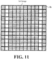
- FIG. 11 is a diagram again showing how the self-image of the phase grating 5 appears on the detection surface 4a, and this time it also includes the end portions of the self-image of the phase grating 5.
- the detection element 4p on the detection surface 4a is highlighted with thick lines.
- the detection element 4p is divided into four rows for each of the detection elements 4p located at the portion where the central portion of the self-image is projected, one dark line appears at the first row, and one dark line appears at the third row. In the detection elements 4p located at the center, all of the self-image dark lines appear with this pattern.
- the dark line of the self-image does not appear as the same pattern.
- the position and number of appearance of the dark line of the self-image are different for each detection element 4p.
- the reason that the pattern of the dark line appearing on the detection element 4p is changed is that the array of absorption lines 5a arranged at both end portions of the self-image is devised.
- the array pitch of the dark lines constituting the self-image of the phase grating 5 on the detection surface 4a is different between the center portion of the self-image and both end portions.
- the array pitch of the dark lines of the self-image at both end portions is shorter than the array pitch of the dark lines of the self-image at the center portion. Therefore, the position and number of dark lines appearing on the detection element 4p are not constant between detection elements 4p.
- the array pitch at both end portions is shorter than the array pitch at the center portion is merely an example of the embodiment.
- the array pitch at both end portions may be longer than the array pitch at the center portion.
- the array pitch of the dark lines of phase grating 5 at both end portions is not an integer multiple of the array pitch of the detection elements 4p 4a and the absorption pitch of the absorption lines 6a of the absorption grating 6a.
- the dark lines of the self-image and the detection elements 4p are arranged at a constant pitch, so the position and number of the dark lines appearing on the detection elements 4p do not differ at all detection elements 4p. Focusing on a certain detection element 4p, the appearance pattern of dark lines on the detection element 4p is taken as a reference pattern. Then, looking at each of the detection elements 4p of the detection element 4p arranged in the vertical direction, the appearance pattern of the dark line changes little by little from the reference pattern. After reaching a certain pattern, it approaches the reference pattern again and returns to the reference pattern. After that, this pattern change is repeated.
- detection elements 4p having the same position and number of dark lines appearing on the detection element 4p appear at equal intervals.
- the detection elements 4p whose dark line appearance patterns are the same are located, for example, 20 positions apart in the vertical direction.
- the subject M in the X-ray phase contrast imaging apparatus of the present invention is configured to appear in the center portion of the self-image of the phase grating 5. Therefore, both end portions of the self-image of the phase grating 5 are the result of imaging of the X-rays not passing through subject M, and have no disturbance due to the influence of the subject M.
- FIG. 12 shows how the self-image of the phase grating 5 and the absorption grating 6 interfere at both end portions of the self-image.
- the array pitch of the dark lines of the self-image of the phase grating 5 and the array pitch of the absorption lines 6a of the absorption grating 6 are identical on the detection surface 4a of the FPD 4, and therefore, the self-image of the phase grating 5 and the absorption grating 6 do not cause interference fringe with each other.
- This description is directed to the center portion of the self-image.
- the absorption grating 6 and the self-image interfere with each other to cause an interference fringe as shown on the right side of FIG. 12 .
- the array pitch of the self-image of the phase grating 5 is shorter than the array pitch of the absorption lines 6a of the absorption grating 6.
- the array pitch of the dark lines of the phase grating 5 at both end portions is not an integer multiple of the array pitch of the absorption lines 6a of the absorption grating 6. Therefore, at both end portions of the self-image, the position of the dark line of the self-image appearing in the vicinity of each absorption line 6a is not constant between absorption lines 6a.
- the dark lines of the self-image and the absorption lines 6a are arranged at a constant pitch, so the position of the dark lines appearing in the vicinity of the absorption line 6a does not differ at all absorption lines 6a.
- the dark line gradually deviates from the absorption line 6a.
- the absorption line 6a and the dark line have reached a state in which they do not overlap
- the absorption line 6a again overlaps the dark line
- the dark line just again overlaps the absorption line 6a.
- this change is repeated.
- the array pitch of the detection elements 4p is twice the array pitch of the absorption lines 6a
- the dark line of the self-image just overlaps every 40 absorption lines 6a arrayed in the vertical direction.
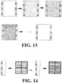
- FIG. 13 again shows the interference image obtained when imaging how the self-image of the phase grating 5 and the absorption grating 6 interfere while moving the absorption grating 6 in the array direction of the absorption lines 6a, and this time, it also includes the end portions of the self-image of the phase grating 5.
- an interference fringe appears at both end portions.
- the center portion of the interference image the center portion of the self-image of the phase grating 5 appears.
- the fact that no interference fringe appears in this portion has already been explained with reference to FIG. 6 .
- both end portions of the self-image of the phase grating 5 both end portions of the interference image appear.
- the fact that an interference fringe appears in this portion has already been explained with reference to FIG. 12 .
- the interference fringe caused by the interference of the self-image of the phase grating 5 and the absorption grating 6 is reflected as shown in FIG. 13 .
- This interference fringe is configured by alternatingly arranging bright and dark areas.
- the bright portion of the interference fringe is located at the upper end of the interference image.
- the light portion gradually moves toward the lower side of the interference image.
- the upper end of the interference image returns to the bright portion again.
- Such a movement of the interference fringe is caused by the relative movement of the absorption grating 6 and the self-image of the phase grating 5 described with reference to FIG. 12 .
- the place where the absorption line 6a and the dark line of the self-image just overlap moves toward the lower side of the self-image.
- the bright portion in the interference fringe on the interference image also moves downward following this.
- FIG. 14 shows the state in which the bright portion of the interference fringe appears at the upper end of the interference image at both ends of the interference image.
- the absorption line 6a of the absorption grating 6 and the dark line of the phase grating 5 are just overlapped.
- the right side of FIG. 14 shows the state in which the bright portion of the interference fringe appears at the upper end of the interference image at both ends of the interference image.
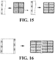
- the left side of FIG. 15 shows the state in which the bright portion of the interference fringe is further shifted downward from the state shown in the right side of FIG. 14 at both ends of the interference image.
- the absorption line 6a of the absorption grating 6 and the dark line of the phase grating 5 are further shifted.
- the right side of FIG. 15 shows the state in which the bright portion of the interference fringe appears at a position further shifted toward the lower side of the interference image at both ends of the interference image.
- the absorption line 6a of the absorption grating 6 and the dark line of the phase grating 5 are not overlapped.
- the position calculation unit 11 in FIG. 1 detects the relative position of the self-image of the phase grating 5 with respect to the absorption grating 6 based on the above-described principle. At both ends of the consecutively captured interference image, the interference fringe inherent in the interference image is reflected. Therefore, the position calculation unit 11 can detect the relative position of the self-image of the phase grating 5 with respect to the absorption grating 6 for each of the interference images. The position calculation unit 11 calculates the relative position of the phase grating 5 and the absorption grating 6 on the basis of the difference in the detected amount of X-rays that differs between detection elements 4p located in the area where both end portions of the phase grating 5 on the detection surface 4a appear.
- the position calculation unit 11 detects the moire (interference fringe) occurred between the image of the pattern of the reference area appeared on the detection surface and the pattern on the absorption grating and calculate the relative position between the phase grating 5 and the absorption grating 6. Further, at this time, the position calculation unit 11 also calculates the position of the X-ray source 3 with respect to the phase grating 5 and the absorption grating 6. This is because the way of appearing the interference fringe changes depends on the relative position of the three members, i.e., the X-ray source 3, the phase grating 5, and the absorption grating 6.
- the detection result on the relative position of the self-image of the phase grating 5 with respect to the absorption grating 6 detected by the position calculation unit 11 is sent to the self-image generation unit 12 together with the interference image.
- the self-image generation unit 12 corrects the calculation related to the self-image generation, generates a self-image of the phase grating 5, and generates a self-image in which the self-image is reflected.
- the self-image generation unit 12 is configured to generate an image of the phase grating 5 based on an image in which the images of the phase grating 5 obtained by continuous image capturing while changing the positional relationship between the image of the phase grating 5 and the absorption grating 6 are overlapped.
- the self-image generation unit 12 according to the present invention is characterized in that a correction is performed by referring to the calculated relative position particularly when generating an image of the phase grating 5 based on the output of the FPD 4.
- the generated self-image image is sent to the fluoroscopic image generation unit 13.
- the fluoroscopic image generation unit 13 generates a fluoroscopic image in which the distribution of the phase contrast inside the subject M is imaged based on the self-image. Based on this operation, the operation of the X-ray phase contrast imaging apparatus of the present invention is completed.
- the left end of the center portion of the self-image of the phase grating 5 is in a state in which the absorption line 6a just overlaps the self-image as shown in FIG. 16 .
- the interference fringe appeared on the right side of the interference image in FIG. 16 is actually the same as the interference fringe described with reference to the right side of FIG. 15 . Therefore, the right end of the center portion of the self-image of the phase grating 5 is in a state in which the absorption line 6a does not overlap the self-image as shown in FIG. 16 .
- the subject rotation mechanism 17 is provided for the purpose of rotating the subject M with respect to each of the parts 3, 4, 5, and 6.
- the subject rotation control unit 18 is provided for the purpose of controlling the subject rotation mechanism 17.
- a plurality of fluoroscopic images generated while rotating the subject M is sent to the tomographic image generation unit 14.
- the tomographic image generation unit 14 reconstructs a plurality of fluoroscopic images to generate a tomographic image of the subject M in which the phase contrast distribution of the subject M is mapped.
- it is necessary to perform image capturing of the self-image a plurality of times. Therefore, in order to acquire the tomographic image, a considerable number of self-images have to be captured.
- the part for fixing the phase grating 5 thermally expands, which moves the self-image of the phase grating 5 little by little on the detection surface 4a.
- CT imaging of the subject M can also be performed.
- each of the parts 11, 12, 13, 14, 16, and 18 according to the present invention is realized by executing various programs by the CPU provided in the apparatus. Instead of the CPU, each part may be realized by an individual microcomputer.
- the apparatus of the present invention is provided with the phase grating 5 in which a center portion and both end portions are provided. Although grating absorbers are arrayed in each area, their array pitches are different.
- the image (grating image) of the phase grating 5 focused on the detection surface interferes with the absorption grating 6 provided so as to cover the detection surface.
- image capturing with a fringe scanning method or an edge illumination method since no interference fringe occurs in the portion where the center portion of the detection surface appears. Therefore, in cases where no subject M is arranged, there is no difference in the detection amount of X-rays between detection elements 4p.
- the self-image of the phase grating 5 and the absorption grating 6 interfere and an interference fringe occurs.
- the appearance position of this interference fringe represents the relative position between the self-image and the absorption grating 6 on the detection surface.
- Both end portions of the phase grating 5 are reflected in the captured interference image, and in the interference image, the center portion of the phase grating 5 is located in a different part.
- the present invention is not limited to the above-described configuration and may be modified as follows.
- FIG. 18 shows a phase grating 5 according to this modified example.
- the phase grating 5 according to this modified example is also provided with a center portion that passes an X-ray beam which passes through the subject M and both end portions that pass an X-ray beam which does not pass through the subject M.
- the configuration of both end portions is the same as that of the phase grating 5 of Example 1.
- the absorption line 5a of the phase grating 5 is inclined with respect to the direction that the absorption line 6a of the absorption grating 6 extends.
- the array pitch of the absorption lines 5a of the phase grating 5 is the same as the array pitch of the absorption lines 6a.
- the direction of the array differs between the absorption line 6a and the absorption line 5a in the center portion of the phase grating 5.
- the direction that the grating absorber extends in the center portion of the phase grating 5 is inclined from the direction that the grating absorber extends at both end portions of the phase grating 5, and the direction that the absorption line 6a in the absorption grating 6 extends coincides with the direction that the grating absorber at both end portions of phase grating 5 extends.
- this modified example it is possible to perform imaging of the self-image of the phase grating 5 without moving the absorption grating 6 with respect to the FPD 4.
- this modified example since the phase grating 5 is inclined with respect to the absorption grating 6, an interference fringe occurs between the absorption grating 6 and the phase grating 5. It should be careful that this interference fringe is about the self-image related to the center portion of the phase grating 5 and is different from the interference fringe about the self-image at the end portion of the phase grating 5 described with reference to FIG. 12 .
- the interference image obtained in FIG. 19 can be regarded as a single interference image obtained by combining a plurality of interference images different in the relative position between the self-image of the phase grating 5 and the absorption grating 6 described with reference to FIG. 7 in a stripe form. Therefore, the self-image generation unit 12 can generate a self-image based on the interference image of the interference fringe obtained in FIG. 19 .
- the present invention can be applied to an apparatus related to a moire single imaging method as described above.
- an interference fringe also occurs at the center portion, so it is not impossible in principle to know the relative position between the absorption grating 6 and the grating image using the method.
- the interference fringe appearing in the center portion of the self-image of the phase grating by the moire single imaging method is not suitable for finding the relative position between the absorption grating 6 and the grating image because the pitch is too fine.
- it is configured such that both end portions in which the pitch of the grating absorber is adjusted so that a pattern of the interference fringe suitable for knowing the relative position is generated are provided separately from the center portion. So, it is possible to accurately know the positional relationship between the grating image and the absorption grating 6.
- FIG. 20 shows an apparatus configuration related to an edge illumination imaging apparatus.
- the multi-slit 3b is not provided, and the shadow of the grating S is reflected on the FPD 4.
- This grating S is provided in place of the phase grating 5 in Example 1, and has the same shape as that of the phase grating 5 described in FIG. 10 .
- the phase grating in Example 1 is a term used when describing Talbot interference.
- it is merely called a grating S since no Talbot interference is utilized.
- the array pitch of the absorption lines in the grating S is wider than the array pitch of the absorption lines 5a in the phase grating 5.
- FIG. 21 shows the configuration of the detection surface and the absorption grating 6 of the FPD 4 in this modified example.
- the detection surface 4a of the FPD 4 is configured by arranging detection elements 4p in matrix.
- the absorption line 6a of the absorption grating 6 extends in the lateral direction of the detection surface 4a in the same manner as in Example 1, and is arrayed in the vertical direction of the detection surface 4a.
- the gap of the adjacent absorption lines 6a in the vertical direction is half the width of the detection element 4p
- the width of the absorption line 6a in the array direction is half the width of the detection element 4p.
- the absorption lines 6a are arrayed in the vertical direction at an array pitch corresponding to one detection element 4p.
- the absorption grating 6 is aligned with the FPD 4 so that the absorption line 6a is positioned so as to straddle the adjacent detection elements 4p.
- the edge illumination imaging device is configured to generate an interference image related to the internal structure of the subject M by repeating the image capturing twice. This point will be briefly described.
- FIG. 22 shows a first image capturing of two image capturing.
- the X-rays that have passed through the grating S becomes a striped beam, passes through the subject M, and is incident on the absorption grating 6.
- the striped beam is configured by an array of an X-ray beam that has passed through the slit and is elongated in shape and has a width half the width of the detection element 4p of the FPD 4. Since the absorption grating 6 is located at the position where the lower half of each of the elongated X-ray beams is incident on the absorption line 6a, each of the elongated X-ray beams is absorbed in the lower half, narrowed further and enters the FPD 4.
- This X-ray beam further narrowed in width is incident on a certain detection element 4p.
- the X-ray beam is configured to be incident on the center portion of the detection element 4p.
- the detection element 4p on which this X-ray beam is incident will be referred to as a detection element 4p of an incident target.
- the X-ray beam is merely incident on the center portion of the detection element 4p.
- the traveling direction changes while the X-ray beam passes through the subject M.
- the X-ray beam is incident in a manner shifted in the downward direction of the detection element 4p of the incident target.
- the X-ray beam is prevented by the absorption line 6a of the absorption grating 6 from reaching the detection element 4p of the incident target indicated by hatching.
- the edge illumination imaging device captures the interference image showing the degree to which the X-ray is bent in a downward direction.
- the FPD 4 and the absorption grating 6 are moved upward by half of the detection element 4p with respect to the stripe-shaped X-ray beam. By this operation, the positional relationship between the striped beam and the absorption grating 6 changes.
- FIG. 24 shows a second image capturing of two image capturing.
- the X-rays which has passed through the grating S becomes a striped beam, passes through the subject M, and is incident on the absorption grating 6.
- the striped beam is configured by an array of X-ray beams that have passed through the slit and are formed in an elongated shape. Since the absorption grating 6 is located at the position where the upper half of each of the elongated X-ray beams is incident on the absorption line 6a, each of the elongated X-ray beams is absorbed by the lower half, narrowed further and enters the FPD 4. This X-ray beam further narrowed in width is incident on a certain detection element 4p. At this time, the X-ray beam is configured to be incident on the center portion of the detection element 4p.
- the detection element 4p on which this X-ray beam is incident will be referred to as a detection element 4p of an incident target.
- the X-ray beam is merely incident on the lower half of the detection element 4p.
- the traveling direction changes while the X-ray beam passes through the subject M.
- the elongated X-ray beam is bent downward as shown in the arrow, the X-ray beam is incident in a manner shifted in the upward direction of the detection element 4p of the incident target.
- the X-ray beam is prevented by the absorption line 6a of the absorption grating 6 from reaching the detection element 4p of the incident target indicated by hatching.
- the edge illumination imaging device captures the interference image showing the degree to which the X-ray is bent in an upward direction.
- the edge illumination imaging device generates an interference image in which the changes in the travelling direction of the X-ray by the subject M are imaged based on two captured interference images.
- the interference fringe indicating the relative position between the shadow of the grating S and the absorption grating 6 appears at both ends of the interference image (see FIG. 12 ). According to the apparatus of the present invention, even if the relative position between the shadow of the grating S and the absorption grating 6 is not ideal, without being affected by that, it is possible to perform accurate imaging of the inside of the subject M.
- the principle of the present invention can also be applied to an edge illumination imaging device having no absorption grating 6.
- the device according to this modified example is equipped with an X-ray detector having a scintillator which causes fluorescence when X-rays are incident.
- detection elements are arranged in a two-dimensional matrix. This detection element is configured to detect fluorescence caused by a scintillator.
- An X-ray detector of this type is called an indirect type detector.
- a layer in which the detection elements are arranged will be called a two-dimensional matrix layer.
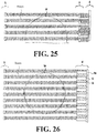
- FIG. 26 shows how the edge illumination imaging is performed using the X-ray detector of this modified example.
- the FPD 4 in this modified example has alternative layers formed by alternately arranging a scintillator element C having a width half of the detection element 4p and a glass element G having a width half of the detection element 4p.
- the scintillator element is made of a material that emits fluorescence when X-rays are incident, and the glass element G is made of glass that does not emit fluorescence even when X-rays are incident.
- the alternative layers are aligned with the two-dimensional matrix layer so that the scintillator elements straddle the adjacent detection elements 4p.
- the configuration of FIG. 26 it is possible to perform the same imaging as in the above-described FIG. 22 . That is, in the detection element 4p of FIG. 22 , the portion where the absorption line 6a of the absorption grating 6 is provided corresponds to the portion where the glass element G of the alternative layer is provided in the detection element 4p of FIG. 26 . In addition, in the detection element 4p of FIG. 22 , the portion exposed from the absorption line 6a corresponds to the portion where the scintillator element C of the alternative layer is provided in the detection element 4p of FIG. 26 . Therefore, by using the configuration of FIG. 26 , it is possible to capture an interference image showing the degree to which the X-rays bend downward.
- the configuration of this modified example is also configured to perform the image capturing of the interference image twice. After the image capturing according to FIG. 26 is completed, before the subsequent second image capturing is performed, the FPD 4 is moved upward by half of the detection element 4p with respect to the stripe-shaped X-ray beam. By this operation, the positional relationship between the striped beam and the FPD 4 changes as shown in FIG. 27 .
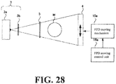
- FIG. 28 illustrates the configuration for moving the FPD 4.
- the FPD moving mechanism 15a is configured to move the FPD 4, and the FPD movement control unit 16a is configured to control the FPD moving mechanism 15a.
- the FPD moving mechanism 15a is provided for the purpose of changing the relative position between the self-image of the phase grating 5 and the FPD 4. The change of this relative position is the same as in Example 1 in that it can be realized by moving the X-ray source 3, the multi-slit 3b, and the phase grating 5.
- the configuration of FIG. 27 it is possible to perform the same imaging as in the above-described FIG. 24 . That is, in the detection element 4p of FIG. 24 , the portion where the absorption line 6a of the absorption grating 6 is provided corresponds to the portion where the glass element G of the alternative layer is provided in the detection element 4p of FIG. 27 . In addition, in the detection element 4p of FIG. 24 , the portion exposed from the absorption line 6a corresponds to the portion where the scintillator element C of the alternative layer is provided in the detection element 4p of FIG. 27 . Therefore, by using the configuration of FIG. 27 , it is possible to capture an interference image showing the degree to which the X-rays bend upward.
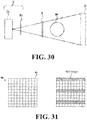
- the detection elements 4p are arranged in a matrix as shown in FIG. 31 . Since the detection element 4p is sufficiently fine, the width of the dark line of the self-image is about the same as the width of the detection element 4p. And the array pitch of the detection elements 4p of the detection surface is smaller than the array pitch of the image of the grating absorber at the detection surface.
- the detection element 4p may be configured to be fine so that the width of the dark line of the self-image becomes wider than the width of the detection element 4p.
- FIG. 32 shows how the array of the detection elements 4p and the self-image of the phase grating 5 interfere at both end portions of the detection surface at the end of the FPD 4.
- the array pitch of the dark lines constituting the self-image is an integer multiple of the width of the detection element 4p, only the self-image is detected as it is on the detection surface.
- the detection element 4p array and the self-image of the phase grating 5 interfere.
- the dark line of the self-image just overlaps the detection element 4p. Focusing on the vertical row located at the right end of the detection element 4p, it is understood that the dark line of the self-image is superimposed every four.
- the array pitch of the dark lines is not an integer multiple of the width of the detection element 4p
- the dark line which just overlaps the detection element 4p on the upper side gradually shifts from the detection element 4p as it goes downward when looking in order of the detection element 4p apart from the detection element 4p by four (4), the detection element 4p apart from the detection element 4p by eight (8), and the detection element 4p apart from the detection element 4p by twelve (12).
- the position calculation unit 11 calculates the relative position between the phase grating 5 and the FPD 4 based on the difference in the detected amount of X-rays that differs among the respective detection elements 4p located in the area where both end portions of the phase grating 5 on the detection surface appears.
- the position calculation unit 11 detects the moire (interference fringe) occurred between the image of the pattern of the reference area appeared on the detection surface and the pattern on the absorption grating and calculate the relative position between the phase grating 5 and the FPD 4. Further, at this time, the position calculation unit 11 also calculates the position of the X-ray source 3 with respect to the phase grating 5 and the FPD 4. This is because the way of appearing the interference fringe changes depends on the relative position of the three members, i.e., the X-ray source 3, the phase grating 5, and the FPD 4.
- This misalignment between the detection element 4p and dark line can be observed by the change of the X-ray dose detected by the detection element 4p. That is, since the detection element 4p at the upper end position just overlap the dark line of the self-image, almost no X-ray is detected. Looking at the output of the detection element 4p in order of a detection element away by four (4), the detection element 4p away from by eight (8), the detection element 4p away from twelve (12), and the detection element 4p away from by sixteen (16), the detection element gradually detects more X-rays. This is because overlapping of dark lines is gradually eliminated.
- the relative position between the array of the detection element 4p and the self-image of the phase grating 5 can be calculated.
- the calculated relative position can be used to correct the captured self-image. That is, the captured self-image is disturbed by the fact that the relative position between the array of the detection element 4p and the self-image of the phase grating 5 is not ideal. If the relative position can be accurately measured, this disturbance can be removed by correction.
- the present invention can also be applied to a device other than a device having the absorption grating 6. That is, in a detection surface, detection elements 4p each having a predetermined size are arranged in a matrix. Therefore, the FPD 4 discretely samples the X-rays to generate an interference image. Therefore, interference may occur between the array of the detection element 4p and the grating image on the detection surface. Based on this principle, an interference fringe is generated at the portion where the reference area of the phase grating 5 appears in the interference image output from the FPD 4. This interference fringe represents the relative position between the phase grating 5 and the FPD 4.
- Both end portions of the phase grating 5 are reflected in the captured interference image, and in the interference image, the center portion of the phase grating 5 is located at a different portion. For this reason, according to the present invention, there is no need to separately perform image capturing in the absence of the subject M to grasp the relative position between the phase grating 5 and the FPD 4. This is because in the interference image, an interference fringe representing the relative position between the grating image and the FPD 4 appears apart from the area in which the subject M appears.
- Example 1 In the configuration of Example 1, the interference image is captured in one shot, but the present invention is not limited to this configuration. It is also possible to generate an interference image by consecutively capturing a plurality of images and adding them together.
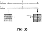
- FIG. 33 illustrates the imaging method of the interference image in Example 1.
- Example 1 it is configured such that an X-ray detection is continuously performed during one X-ray irradiation and the detection data accumulated in the FPD 4 is read after completion of the X-ray irradiation.
- an imaging method only one image is obtained during one X-ray irradiation.
- Such an imaging method has the following problems. Due to the thermal expansion of the optical system, vibration, etc., during imaging, the position of the phase grating 5 shifts or the radiation generation point of the radiation source 3 deviates from the ideal position. Therefore, there is a possibility that errors occur. That is, as shown in FIG.
- the absorption line 6a of the absorption grating 6 and the self-image of the phase grating 5 are just overlapped.
- the relative position between the phase grating 5 and the absorption grating 6 gradually changes and the position of the absorption line 6a and the position of the self-image of the phase grating 5 also deviate accordingly.
- this situation is not taken into consideration, and an interference image is generated assuming that the relative position of the phase grating 5 and the absorption grating 6 does not change from the start of imaging.
- FIG. 34 illustrates the configuration of this modified example.
- the FPD 4 is read many times during one radiation imaging and a plurality of images is generated based on the result.
- the image generated at this time is an image in which the interference image is insufficiently exposed and it is called an instantaneous interference image.
- the interference fringe formed by the interference of the absorption grating 6 and the self-image of the phase grating 5 appears.
- the interference fringe at the start of imaging represents that the absorption line 6a of the absorption grating 6 and the dark line of the self-image of the phase grating 5 are just overlapped.
- the interference image of this modified example is generated by adding only the instantaneous interference images captured when the relative position between the absorption grating 6 and the phase grating 5 in the consecutively captured instantaneous interference image has not changed from the start of imaging.
- By generating the interference image as described above it is possible to generate an interference image captured with the positional relationship between the absorption grating 6 and the phase grating 5 certainly in a certain state. Further, when it is detected that the relative position has changed from the start of imaging, it is possible to perform long-time exposure imaging by continuously performing imaging by performing an operation of returning the relative position to the imaging start position without adding the changed instantaneous interference image.
- the optical system is vibrating.
- the interference fringe appeared at the end portion of the instantaneous interference image changes periodically.
- the interference image in this case is also generated by adding only the instantaneous interference images captured when the relative position between the absorption grating 6 and the phase grating 5 in the consecutively captured instantaneous interference image has not changed from the start of imaging. Therefore, the instantaneous interference image to be added becomes those captured at a certain time interval that is longer than the temporal interval necessary for image continuous capturing. Note that in this case, it is more preferable to determine the interval of the consecutive imaging in consideration of the natural frequency of the anti-vibration function.
- This modified example can be applied not only to Example 1 but also to imaging of other modified examples.
- the patterns provided in the phase grating and the absorption grating in the present invention are in the form of stripes, the present invention is not limited to this configuration.
- the pattern may be other patterns such as, e.g., a checkered pattern.
Landscapes
- Health & Medical Sciences (AREA)
- Life Sciences & Earth Sciences (AREA)
- Engineering & Computer Science (AREA)
- Medical Informatics (AREA)
- Pathology (AREA)
- General Health & Medical Sciences (AREA)
- Physics & Mathematics (AREA)
- Nuclear Medicine, Radiotherapy & Molecular Imaging (AREA)
- Radiology & Medical Imaging (AREA)
- Surgery (AREA)
- Veterinary Medicine (AREA)
- Biomedical Technology (AREA)
- Heart & Thoracic Surgery (AREA)
- Molecular Biology (AREA)
- High Energy & Nuclear Physics (AREA)
- Animal Behavior & Ethology (AREA)
- Biophysics (AREA)
- Public Health (AREA)
- Optics & Photonics (AREA)
- Chemical & Material Sciences (AREA)
- Analytical Chemistry (AREA)
- Biochemistry (AREA)
- General Physics & Mathematics (AREA)
- Immunology (AREA)
- Pulmonology (AREA)
- Theoretical Computer Science (AREA)
- Apparatus For Radiation Diagnosis (AREA)
- Measurement Of Radiation (AREA)
Applications Claiming Priority (2)
| Application Number | Priority Date | Filing Date | Title |
|---|---|---|---|
| JP2016118933 | 2016-06-15 | ||
| PCT/JP2017/010511 WO2017217049A1 (fr) | 2016-06-15 | 2017-03-15 | Dispositif d'imagerie par rayonnement |
Publications (2)
| Publication Number | Publication Date |
|---|---|
| EP3473183A1 true EP3473183A1 (fr) | 2019-04-24 |
| EP3473183A4 EP3473183A4 (fr) | 2020-02-12 |
Family
ID=60664049
Family Applications (1)
| Application Number | Title | Priority Date | Filing Date |
|---|---|---|---|
| EP17812955.7A Withdrawn EP3473183A4 (fr) | 2016-06-15 | 2017-03-15 | Dispositif d'imagerie par rayonnement |
Country Status (5)
| Country | Link |
|---|---|
| US (1) | US10859512B2 (fr) |
| EP (1) | EP3473183A4 (fr) |
| JP (1) | JP6680356B2 (fr) |
| CN (1) | CN109328035B (fr) |
| WO (1) | WO2017217049A1 (fr) |
Families Citing this family (1)
| Publication number | Priority date | Publication date | Assignee | Title |
|---|---|---|---|---|
| EP3821810A1 (fr) * | 2019-11-13 | 2021-05-19 | Koninklijke Philips N.V. | Suivi de position de réseaux actifs dans l'imagerie sur fond noir à contraste de phase à base de réseaux |
Family Cites Families (17)
| Publication number | Priority date | Publication date | Assignee | Title |
|---|---|---|---|---|
| JP5586986B2 (ja) * | 2010-02-23 | 2014-09-10 | キヤノン株式会社 | X線撮像装置 |
| JP5548085B2 (ja) | 2010-03-30 | 2014-07-16 | 富士フイルム株式会社 | 回折格子の調整方法 |
| JP2012020107A (ja) * | 2010-06-16 | 2012-02-02 | Fujifilm Corp | 放射線位相画像撮影装置 |
| JP2012103237A (ja) * | 2010-10-14 | 2012-05-31 | Canon Inc | 撮像装置 |
| EP2633813B1 (fr) | 2010-10-29 | 2015-02-25 | FUJIFILM Corporation | Dispositif d'imagerie de rayonnement par contraste de phase |
| US20130225692A1 (en) | 2010-11-04 | 2013-08-29 | Peter Stein | Formulations comprising polyethylene glycol |
| JP2012166010A (ja) * | 2011-01-26 | 2012-09-06 | Fujifilm Corp | 放射線画像撮影装置および放射線画像検出器 |
| JP5787597B2 (ja) * | 2011-04-26 | 2015-09-30 | キヤノン株式会社 | 撮像装置 |
| JP5885405B2 (ja) * | 2011-06-13 | 2016-03-15 | キヤノン株式会社 | 撮像装置、干渉縞解析プログラム及び干渉縞解析方法 |
| JP2013050441A (ja) * | 2011-08-03 | 2013-03-14 | Canon Inc | 波面測定装置、波面測定方法、及びプログラム並びにx線撮像装置 |
| JP2013063099A (ja) * | 2011-09-15 | 2013-04-11 | Canon Inc | X線撮像装置 |
| JP2013070867A (ja) * | 2011-09-28 | 2013-04-22 | Canon Inc | 撮像装置及び撮像方法 |
| JP6182840B2 (ja) | 2012-06-25 | 2017-08-23 | ソニー株式会社 | 放射線検出器の製造方法 |
| JP2014090967A (ja) | 2012-11-06 | 2014-05-19 | Canon Inc | X線撮像装置 |
| CN103829964A (zh) * | 2012-11-27 | 2014-06-04 | Ge医疗系统环球技术有限公司 | X射线检测器、准直仪、ct设备及其所用的方法 |
| JP2014178130A (ja) * | 2013-03-13 | 2014-09-25 | Canon Inc | X線撮像装置及びx線撮像システム |
| US9726622B2 (en) * | 2013-10-31 | 2017-08-08 | Tohoku University | Non-destructive inspection device |
-
2017
- 2017-03-15 CN CN201780037450.XA patent/CN109328035B/zh not_active Expired - Fee Related
- 2017-03-15 JP JP2018523320A patent/JP6680356B2/ja active Active
- 2017-03-15 WO PCT/JP2017/010511 patent/WO2017217049A1/fr not_active Ceased
- 2017-03-15 EP EP17812955.7A patent/EP3473183A4/fr not_active Withdrawn
- 2017-03-15 US US16/309,820 patent/US10859512B2/en not_active Expired - Fee Related
Also Published As
| Publication number | Publication date |
|---|---|
| CN109328035B (zh) | 2022-05-10 |
| WO2017217049A1 (fr) | 2017-12-21 |
| JP6680356B2 (ja) | 2020-04-15 |
| EP3473183A4 (fr) | 2020-02-12 |
| CN109328035A (zh) | 2019-02-12 |
| US20190175126A1 (en) | 2019-06-13 |
| US10859512B2 (en) | 2020-12-08 |
| JPWO2017217049A1 (ja) | 2019-01-10 |
Similar Documents
| Publication | Publication Date | Title |
|---|---|---|
| RU2562879C2 (ru) | Устройство для фазоконтрастного формирования изображений, содержащее перемещаемый элемент детектора рентгеновского излучения, и соответствующий способ | |
| KR101668219B1 (ko) | 비파괴 검사 장치 | |
| US9402594B2 (en) | X-ray detector of a grating-based phase contrast x-ray device and method for operating a grating-based phase contrast x-ray device | |
| US7983381B2 (en) | X-ray CT system for x-ray phase contrast and/or x-ray dark field imaging | |
| US8451975B2 (en) | Radiographic system, radiographic method and computer readable medium | |
| US9750465B2 (en) | Scanning system for differential phase contrast imaging | |
| US8005185B2 (en) | Method to determine phase and/or amplitude between interfering, adjacent x-ray beams in a detector pixel in a talbot interferometer | |
| JP5961614B2 (ja) | 位相差イメージングのための格子装置、位相差イメージングのための装置、当該装置を有するx線システム、当該装置の使用方法 | |
| JP6460226B2 (ja) | X線撮影装置 | |
| US10365235B2 (en) | Radiation phase-contrast imaging device | |
| US20140286477A1 (en) | Radiation photographing apparatus | |
| JP2011224330A (ja) | 放射線撮影システム及びそのオフセット補正方法 | |
| JP2013164339A (ja) | X線撮像装置 | |
| US10859512B2 (en) | X-ray phase contrast imaging apparatus | |
| JP6656391B2 (ja) | 放射線位相差撮影装置 | |
| JP2014012029A (ja) | 放射線撮影システム及び画像処理方法 | |
| JP6631707B2 (ja) | X線位相差撮像システム | |
| JP2013150780A (ja) | 放射線撮影装置及び放射線撮影方法 | |
| JP2011206161A (ja) | 放射線撮影システム及びその画像生成方法 | |
| JP6641725B2 (ja) | X線撮影装置 | |
| JP2011206162A (ja) | 放射線撮影システム及び方法 | |
| WO2013027519A1 (fr) | Dispositif de radiographie et procédé de déroulement | |
| JP6732169B2 (ja) | 放射線位相差撮影装置 | |
| US10276276B1 (en) | Radiation phase-contrast image capturing device | |
| JP6287813B2 (ja) | 放射線位相差撮影装置 |
Legal Events
| Date | Code | Title | Description |
|---|---|---|---|
| STAA | Information on the status of an ep patent application or granted ep patent |
Free format text: STATUS: THE INTERNATIONAL PUBLICATION HAS BEEN MADE |
|
| PUAI | Public reference made under article 153(3) epc to a published international application that has entered the european phase |
Free format text: ORIGINAL CODE: 0009012 |
|
| STAA | Information on the status of an ep patent application or granted ep patent |
Free format text: STATUS: REQUEST FOR EXAMINATION WAS MADE |
|
| 17P | Request for examination filed |
Effective date: 20181213 |
|
| AK | Designated contracting states |
Kind code of ref document: A1 Designated state(s): AL AT BE BG CH CY CZ DE DK EE ES FI FR GB GR HR HU IE IS IT LI LT LU LV MC MK MT NL NO PL PT RO RS SE SI SK SM TR |
|
| AX | Request for extension of the european patent |
Extension state: BA ME |
|
| DAV | Request for validation of the european patent (deleted) | ||
| DAX | Request for extension of the european patent (deleted) | ||
| A4 | Supplementary search report drawn up and despatched |
Effective date: 20200115 |
|
| RIC1 | Information provided on ipc code assigned before grant |
Ipc: G01N 23/04 20180101ALI20200109BHEP Ipc: G01N 23/041 20180101ALI20200109BHEP Ipc: A61B 6/00 20060101AFI20200109BHEP |
|
| STAA | Information on the status of an ep patent application or granted ep patent |
Free format text: STATUS: THE APPLICATION HAS BEEN WITHDRAWN |
|
| 18W | Application withdrawn |
Effective date: 20220204 |