EP3473187B1 - Appareil à rayons x et méthode - Google Patents
Appareil à rayons x et méthode Download PDFInfo
- Publication number
- EP3473187B1 EP3473187B1 EP18204140.0A EP18204140A EP3473187B1 EP 3473187 B1 EP3473187 B1 EP 3473187B1 EP 18204140 A EP18204140 A EP 18204140A EP 3473187 B1 EP3473187 B1 EP 3473187B1
- Authority
- EP
- European Patent Office
- Prior art keywords
- ray
- image
- ray emitter
- user
- ray apparatus
- Prior art date
- Legal status (The legal status is an assumption and is not a legal conclusion. Google has not performed a legal analysis and makes no representation as to the accuracy of the status listed.)
- Active
Links
Images


Classifications
-
- A—HUMAN NECESSITIES
- A61—MEDICAL OR VETERINARY SCIENCE; HYGIENE
- A61B—DIAGNOSIS; SURGERY; IDENTIFICATION
- A61B6/00—Apparatus or devices for radiation diagnosis; Apparatus or devices for radiation diagnosis combined with radiation therapy equipment
- A61B6/44—Constructional features of apparatus for radiation diagnosis
- A61B6/4417—Constructional features of apparatus for radiation diagnosis related to combined acquisition of different diagnostic modalities
-
- A—HUMAN NECESSITIES
- A61—MEDICAL OR VETERINARY SCIENCE; HYGIENE
- A61B—DIAGNOSIS; SURGERY; IDENTIFICATION
- A61B6/00—Apparatus or devices for radiation diagnosis; Apparatus or devices for radiation diagnosis combined with radiation therapy equipment
- A61B6/08—Auxiliary means for directing the radiation beam to a particular spot, e.g. using light beams
-
- A—HUMAN NECESSITIES
- A61—MEDICAL OR VETERINARY SCIENCE; HYGIENE
- A61B—DIAGNOSIS; SURGERY; IDENTIFICATION
- A61B6/00—Apparatus or devices for radiation diagnosis; Apparatus or devices for radiation diagnosis combined with radiation therapy equipment
- A61B6/44—Constructional features of apparatus for radiation diagnosis
- A61B6/4476—Constructional features of apparatus for radiation diagnosis related to motor-assisted motion of the source unit
-
- A—HUMAN NECESSITIES
- A61—MEDICAL OR VETERINARY SCIENCE; HYGIENE
- A61B—DIAGNOSIS; SURGERY; IDENTIFICATION
- A61B6/00—Apparatus or devices for radiation diagnosis; Apparatus or devices for radiation diagnosis combined with radiation therapy equipment
- A61B6/46—Arrangements for interfacing with the operator or the patient
- A61B6/461—Displaying means of special interest
- A61B6/463—Displaying means of special interest characterised by displaying multiple images or images and diagnostic data on one display
-
- A—HUMAN NECESSITIES
- A61—MEDICAL OR VETERINARY SCIENCE; HYGIENE
- A61B—DIAGNOSIS; SURGERY; IDENTIFICATION
- A61B6/00—Apparatus or devices for radiation diagnosis; Apparatus or devices for radiation diagnosis combined with radiation therapy equipment
- A61B6/52—Devices using data or image processing specially adapted for radiation diagnosis
-
- A—HUMAN NECESSITIES
- A61—MEDICAL OR VETERINARY SCIENCE; HYGIENE
- A61B—DIAGNOSIS; SURGERY; IDENTIFICATION
- A61B6/00—Apparatus or devices for radiation diagnosis; Apparatus or devices for radiation diagnosis combined with radiation therapy equipment
- A61B6/54—Control of apparatus or devices for radiation diagnosis
-
- A—HUMAN NECESSITIES
- A61—MEDICAL OR VETERINARY SCIENCE; HYGIENE
- A61B—DIAGNOSIS; SURGERY; IDENTIFICATION
- A61B6/00—Apparatus or devices for radiation diagnosis; Apparatus or devices for radiation diagnosis combined with radiation therapy equipment
- A61B6/44—Constructional features of apparatus for radiation diagnosis
- A61B6/4429—Constructional features of apparatus for radiation diagnosis related to the mounting of source units and detector units
- A61B6/4452—Constructional features of apparatus for radiation diagnosis related to the mounting of source units and detector units the source unit and the detector unit being able to move relative to each other
-
- A—HUMAN NECESSITIES
- A61—MEDICAL OR VETERINARY SCIENCE; HYGIENE
- A61B—DIAGNOSIS; SURGERY; IDENTIFICATION
- A61B6/00—Apparatus or devices for radiation diagnosis; Apparatus or devices for radiation diagnosis combined with radiation therapy equipment
- A61B6/44—Constructional features of apparatus for radiation diagnosis
- A61B6/4429—Constructional features of apparatus for radiation diagnosis related to the mounting of source units and detector units
- A61B6/4464—Constructional features of apparatus for radiation diagnosis related to the mounting of source units and detector units the source unit or the detector unit being mounted to ceiling
-
- A—HUMAN NECESSITIES
- A61—MEDICAL OR VETERINARY SCIENCE; HYGIENE
- A61B—DIAGNOSIS; SURGERY; IDENTIFICATION
- A61B6/00—Apparatus or devices for radiation diagnosis; Apparatus or devices for radiation diagnosis combined with radiation therapy equipment
- A61B6/54—Control of apparatus or devices for radiation diagnosis
- A61B6/545—Control of apparatus or devices for radiation diagnosis involving automatic set-up of acquisition parameters
-
- A—HUMAN NECESSITIES
- A61—MEDICAL OR VETERINARY SCIENCE; HYGIENE
- A61B—DIAGNOSIS; SURGERY; IDENTIFICATION
- A61B6/00—Apparatus or devices for radiation diagnosis; Apparatus or devices for radiation diagnosis combined with radiation therapy equipment
- A61B6/58—Testing, adjusting or calibrating thereof
- A61B6/587—Alignment of source unit to detector unit
Definitions
- the X-ray apparatus 100 may be controlled via the workstation 110 or may be controlled by the controller 150 included in the X-ray apparatus 100. Accordingly, the user may control the X-ray apparatus 100 via the workstation 110 or may control the X-ray apparatus 100 via the manipulator 140 and the controller 150 included in the X-ray apparatus 100. In other words, the user may remotely control the X-ray apparatus 100 via the workstation 110 or may directly control the X-ray apparatus 100.
- a prepare command for performing a pre-heating operation for X-ray radiation may be input through the switch, and then, when the user pushes the switch once more, the radiation command for performing substantial X-ray radiation may be input through the switch.
- the controllers 113 and 150 generate signals corresponding to the commands input through the switch manipulation, that is, a prepare signal, and transmit the generated signals to the high voltage generator 121 for generating a high voltage for generating the X-ray.
- the communicator may include one or more elements enabling communication with external apparatuses.
- the communicator may include a local area communication module, a wired communication module, and a wireless communication module.
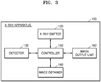
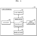
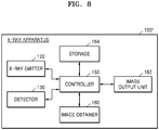
- the X-ray system 1000 may include the X-ray apparatus 100 and the workstation 110.
- the X-ray apparatus 100 may include the X-ray emitter 120 that radiates X-rays to an object 10, the detector 130 that detects X-rays radiated from the X-ray emitter 120 and transmitted through the object 10, the manipulator 140 that provides a user interface (UI) for manipulating the X-ray apparatus 100, and an image obtainer 160 that is attached to a side of the X-ray emitter 120 and photographs the object 10.
- UI user interface
- the workstation 110 may include the controller 113.
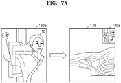
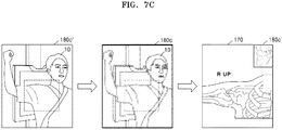
- the controller 113 may generate the image marker 180 (see FIG. 2 ) by performing image processing on a captured image of the object 10 obtained by the image obtainer 160. Also, the controller 113 may generate the X-ray image 170 (see FIG. 2 ) of the object 10 based on X-rays detected by the detector 130, and may cause the image marker 180 to overlap the generated X-ray image 170.
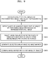
- the X-ray apparatus obtains a captured image of an object by continuously photographing the object and selects a representative still image that represents a candidate body part of the object.
- the X-ray apparatus may obtain a plurality of still images of the object by continuously photographing the object.
- the captured image of the object may be different from an X-ray image obtained by X-ray imaging the object.
- the plurality of still images may be obtained by a camera for obtaining an image.
- the image obtainer 160 (see FIG. and 3) may obtain a plurality of still images of the object 10 (see FIG. 2 ) by continuously photographing the object 10.
- an X-ray apparatus obtains a plurality of still images by continuously photographing an object, and selects a representative still image that represents a candidate body part of the object among the plurality of still images.
- the representative still image may be a still image obtained by photographing the candidate body part of the object among still images obtained immediately before X-ray imaging among the plurality of still images.
- the obtaining of the plurality of still images and the selecting of the representative still image are the same as those described in operation S501 of FIG. 5 , and thus a repeated explanation thereof will not be provided.
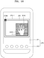
- the image marker 180 may be formed on a region of the X-ray image 170, and the guide image 190 may be included in the image marker 180.
- the guide image 190 may be an image that enables a user to recognize a vertical/horizontal direction of the image marker 180.
- the guide image 190 may be a figure image or a cartoon image including text and/or an arrow.
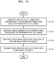
- FIG. 11 is a flowchart of a method performed by the X-ray apparatus 100 of FIG. 3 to generate an image marker including a guide image.
- the X-ray apparatus combines the image marker and the guide image with an X-ray image of the object.
- the guide image may be combined to overlap a region of the image marker.
- the image marker combined with the guide image may overlap a region of the X-ray image obtained by X-ray imaging the object and may be simultaneously displayed along with the X-ray image.
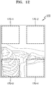
- FIG. 12 is a view for explaining a method of determining a position of an image marker according to an embodiment.
- an X-ray apparatus obtains a plurality of still images by continuously photographing an object and selects a representative still image.
- the obtaining of the plurality of still images and the selecting of the representative still image are the same as those described in operation S501 of FIG. 5 , and thus a repeated explanation thereof will not be provided.
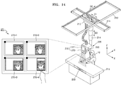
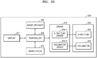
- the X-ray apparatus 200 may include an X-ray emitter 220 that generates X-rays and radiates the X-rays to the object 10, an X-ray detector 230 that detects X-rays transmitted through the object 10, an image obtainer 260 that photographs the object 10 and obtains a captured image of the object 10, and a manipulator 270 that provides an interface for manipulating the X-ray apparatus 200.
- the X-ray emitter 220 and the X-ray detector 230 are respectively the same as the X-ray emitter 120 and the detector 130 of FIG. 1 , and thus a repeated explanation thereof will not be provided.
- the X-ray apparatus 200 may display on the display 271 a UI for displaying information about the irradiation region of the X-ray emitter 220 and the central point of the X-ray emitter 220 to overlap the captured image.
- the information about the irradiation region of the X-ray emitter 220 and the central point of the X-ray emitter 220 may be a plurality of combinations of information, and each of the plurality of combinations of information may overlap the captured image to form a plurality of thumbnail images, for example, first through fourth thumbnail images 270-1 through 270-4.
- the first through fourth thumbnail images 270-1 through 270-4 may be displayed on the display 271.
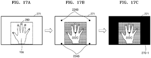
- the X-ray apparatus 200 may match the central point of the X-ray tube to the central point marker 222C' of the object 10a, and may generate the first thumbnail image 270-1 for adjusting the shutter-blade of the collimator based on the collimator coordinates 224B.
- the first thumbnail image 270-1 may be updated in real time.
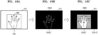
- the X-ray apparatus 200 may generate the second thumbnail image 270-2 including the central point marker 222C" of the object 10a and the X-ray imaged region UI 240A.
- the X-ray apparatus 200 may control a central point of the X-ray tube 222 (see FIG. 20 ) to be matched to the central point marker 222C" and a shutter-blade of the collimator 224 (see FIG. 20 ) to be matched to the X-ray imaged region UI 240A.
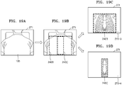
- FIGS. 19A through 19D are views for explaining a method performed by the X-ray apparatus 200 to generate the third thumbnail image 270-3 and the fourth thumbnail image 270-4 based on user experience-based learning data of an object 10b.
- Different guide UIs may be displayed on the third thumbnail image 270-3 and the fourth thumbnail image 270-4 according to an imaging protocol.
- a captured image of the object 10b may be displayed on the display 271.
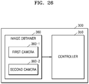
- the second camera 360-2 may be attached to a side of the X-ray emitter 320. In an embodiment, the second camera 360-2 may be attached to a collimator of the X-ray emitter 320. The second camera 360-2 may photograph the object 10 and a candidate region of the object 10 and may obtain captured images of the object 10 and the candidate region of the object 10.
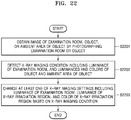
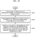
- the X-ray apparatus 300 detects an X-ray imaging condition including a luminance of the examination room, and luminances and colors of the object and the ambient area of the object by performing image processing on the captured image.
- the X-ray apparatus 300 may detect the X-ray imaging condition by performing image recognition on the captured image based on appropriate software and/or algorithms known to those skilled in the art.
- the X-ray apparatus 300 may obtain information about the luminance of the examination room by applying image recognition to the captured image of the examination room obtained by photographing the examination room.
- the X-ray apparatus 300 may obtain information about the luminances and colors of the object and/or the ambient area of the object by applying image recognition to the captured image of the object obtained by photographing the object.
- FIG. 23 is a flowchart of a method performed by the X-ray apparatus 300 of FIG. 21 to change imaging settings according to a luminance of an examination room and a luminance of an X-ray irradiation region.
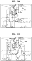
- the X-ray apparatus 300 may determine that the user 20 who stands up performs an action of talking to the object 10.
- the action of the user 20 who is standing and taking to the object 10 may mean that X-ray imaging has ended.
- the X-ray apparatus 300 may recognize an action of the object 10 as well as a behavior of the user 20.
- the X-ray apparatus 300 may recognize a current position of the user 20, that is, information about whether the user 20 is located in front of a door of the examination room or in front of the X-ray apparatus 300.
- the X-ray apparatus 300 may recognize that the user 20 is spaced apart by a predetermined distance from the X-ray apparatus 300 and the object 10 sits up and talks to the user 20, may determine that the X-ray imaging has ended, and may control a brightness of the collimator light source 322 to be reduced and a brightness of the examination room light source 370 to be increased.
- a brightness of the examination room light source 370 may be controlled according to a section or the whole of the examination room.
Landscapes
- Health & Medical Sciences (AREA)
- Life Sciences & Earth Sciences (AREA)
- Engineering & Computer Science (AREA)
- Medical Informatics (AREA)
- Radiology & Medical Imaging (AREA)
- Molecular Biology (AREA)
- Biophysics (AREA)
- Nuclear Medicine, Radiotherapy & Molecular Imaging (AREA)
- Optics & Photonics (AREA)
- Pathology (AREA)
- Physics & Mathematics (AREA)
- Biomedical Technology (AREA)
- Heart & Thoracic Surgery (AREA)
- High Energy & Nuclear Physics (AREA)
- Surgery (AREA)
- Animal Behavior & Ethology (AREA)
- General Health & Medical Sciences (AREA)
- Public Health (AREA)
- Veterinary Medicine (AREA)
- Human Computer Interaction (AREA)
- Computer Vision & Pattern Recognition (AREA)
- Apparatus For Radiation Diagnosis (AREA)
Claims (11)
- Appareil de radiographie (100, 100', 100", 200) permettant de commander la position d'un émetteur de rayons X (120, 220), l'appareil de radiographie (100, 100', 100", 200) comprenant :- un émetteur de rayons X (120, 220) conçu pour générer des rayons X et rayonner les rayons X en direction d'un objet (10, 10a, 10b) ;- un détecteur de rayons X (130, 230) conçu pour détecter les rayons X émis à travers l'objet (10, 10a, 10b) ;- une caméra conçue pour obtenir une image de l'objet (10, 10a, 10b) par photographie de l'objet (10, 10a, 10b), l'image prise étant différente d'une image radiographique obtenue par radiographie de l'objet (10, 10a, 10b) ;caractérisé en ce qu'il comprend en outre :- un organe de commande (113, 150, 250, 350) comportant un processeur d'image conçu pour identifier une zone candidate de l'objet (10, 10a, 10b) et un point central de l'objet (10, 10a, 10b) par réalisation d'un traitement d'image sur l'image obtenue,l'organe de commande (113, 150, 250, 350) étant conçu pour :- calculer une pluralité de formes de zones de rayonnement de l'émetteur de rayons X (120, 220) et de positions de l'émetteur de rayons X (120, 220) par mise en correspondance de la zone candidate de l'objet (10, 10a, 10b) et du point central de l'objet (10, 10a, 10b) avec une pluralité de zones de rayonnement de l'émetteur de rayons X (120, 220) et la pluralité de points centraux de l'émetteur de rayons X (120, 220) correspondant respectivement aux différentes positions de l'émetteur de rayons X (120, 220), la zone candidate étant une zone de l'objet (10, 10a, 10b) à radiographier ; et- générer une pluralité de vignettes dans lesquelles chacune des formes de zones de rayonnement calculées et chacun des points centraux calculés de l'émetteur de rayons X (120, 220) sont en chevauchement avec l'image obtenue ;dans lequel l'appareil de radiographie (100, 100', 100", 200) comprend en outre :- un dispositif d'affichage (111, 141, 162, 271) conçu pour afficher la pluralité de vignettes,- un récepteur d'entrée utilisateur (112, 142) conçu pour recevoir une entrée utilisateur qui sélectionne une vignette parmi la pluralité de vignettes affichées sur le dispositif d'affichage (111, 141, 162, 271), et- un organe d'entraînement (254) conçu pour régler une zone de rayonnement de l'émetteur de rayons X (120, 220) et une position de l'émetteur de rayons X (120, 220) compte tenu de l'entrée utilisateur.
- Appareil de radiographie (100, 100', 100", 200) selon la revendication 1, dans lequel le récepteur d'entrée utilisateur (112, 142) comprend :
un écran tactile intégré dans le dispositif d'affichage (111, 141, 162, 271) et conçu pour recevoir une entrée tactile provenant d'un utilisateur touchant une vignette parmi la pluralité de vignettes affichées sur le dispositif d'affichage (111, 141, 162, 271). - Appareil de radiographie (100, 100', 100", 200) selon la revendication 1, dans lequel le processeur d'image est conçu en outre pour convertir les formes de zones de rayonnement calculées de l'émetteur de rayons X et les points centraux calculés de l'émetteur de rayons X en interfaces utilisateurs (UI) graphiques virtuelles, et
le dispositif d'affichage (111, 141, 162, 271) est conçu en outre pour afficher les UI graphiques virtuelles de telle façon que les UI graphiques virtuelles sont en chevauchement avec l'image obtenue. - Appareil de radiographie (100, 100', 100", 200) selon la revendication 1, dans lequel le dispositif d'affichage (111, 141, 162, 271) est conçu en outre pour afficher une UI affichant le point central de l'objet (10, 10a, 10b) sous la forme d'un premier marqueur et affichant les points centraux calculés de l'émetteur de rayons X (120, 220) sous la forme de deuxièmes marqueurs.
- Appareil de radiographie (100, 100', 100", 200) selon la revendication 4, dans lequel les positions des deuxièmes marqueurs sont corrigées compte tenu d'une entrée utilisateur.
- Appareil de radiographie (100, 100', 100", 200) selon la revendication 1, dans lequel l'organe de commande (113, 150, 250, 350) est conçu en outre pour identifier un utilisateur utilisant l'appareil de radiographie et pour obtenir des informations de paramètre, saisies par l'utilisateur, concernant les zones de rayonnement de l'émetteur de rayons X (120, 220) et les points centraux calculés de l'émetteur de rayons X (120, 220), et
le processeur d'image est conçu en outre pour générer la pluralité de vignettes compte tenu des informations de paramètre correspondant à l'utilisateur identifié. - Appareil de radiographie (100, 100', 100", 200) selon la revendication 6, comprenant en outre un dispositif de stockage (164) conçu pour stocker les informations de paramètre, concernant la pluralité de zones de rayonnement de l'émetteur de rayons X (120, 220) et les points centraux calculés de l'émetteur de rayons X (120, 220), qui sont saisies par l'utilisateur,
dans lequel le processeur d'image est conçu en outre pour obtenir des informations concernant la zone de rayonnement de l'émetteur de rayons X (120, 220) et le point central de l'émetteur de rayons X (120, 220) par analyse des informations de paramètre stockées dans le dispositif de stockage (164). - Procédé de commande de la position d'un émetteur de rayons X (120, 220), le procédé comprenant :- l'obtention (S1501) d'une image d'un objet (10, 10a, 10b) par photographie de l'objet (10, 10a, 10b), ladite image obtenue étant différente d'une image radiographique obtenue par radiographie de l'objet ;caractérisé en ce que le procédé comprend en outre :- l'identification (S1502) d'une zone candidate de l'objet (10, 10a, 10b) et d'un point central de l'objet (10, 10a, 10b) par réalisation d'un traitement d'image sur l'image obtenue ;- le calcul (S1502) d'une pluralité de formes de zones de rayonnement de l'émetteur de rayons X (120, 220) et de positions de l'émetteur de rayons X (120, 220) par mise en correspondance de la zone candidate identifiée de l'objet (10, 10a, 10b) et du point central identifié de l'objet (10, 10a, 10b) avec une pluralité de zones de rayonnement de l'émetteur de rayons X (120, 220) et une pluralité de points centraux de l'émetteur de rayons X (120, 220) correspondant respectivement aux différentes positions de l'émetteur de rayons X (120, 220), la zone candidate étant une zone de l'objet (10, 10a, 10b) à radiographier ;- la génération (S1504) d'une pluralité de vignettes dans lesquelles chacune des formes de zones de rayonnement calculées et chacun des points centraux calculés de l'émetteur de rayons X (120, 220) sont en chevauchement avec l'image obtenue ;- l'affichage de la pluralité de vignettes ;- la réception d'une entrée utilisateur qui sélectionne une vignette parmi la pluralité de vignettes affichées sur un dispositif d'affichage (111, 141, 162, 271) ; et- le réglage (S1505) d'une zone de rayonnement de l'émetteur de rayons X (120, 220) et d'une position de l'émetteur de rayons X (120, 220) compte tenu de l'entrée utilisateur.
- Procédé selon la revendication 8, dans lequel la génération de la pluralité de vignettes comprend :la conversion de la zone candidate de l'objet (10, 10a, 10b) et du point central de l'objet (10, 10a, 10b) en des graphismes virtuels, etl'affichage d'une interface utilisateur (UI) de telle façon que les graphismes virtuels sont en chevauchement avec l'image obtenue.
- Procédé selon la revendication 8, dans lequel l'affichage de la pluralité de vignettes comprend :
l'affichage d'une interface utilisateur (UI) affichant le point central de l'objet (10, 10a, 10b) sous la forme d'un premier marqueur et affichant les points centraux calculés de l'émetteur de rayons X (120, 220) sous la forme de deuxièmes marqueurs. - Procédé selon la revendication 8, dans lequel la génération des vignettes comprend :l'identification d'un utilisateur utilisant l'appareil de radiographie (100, 100', 100", 200) comprenant l'émetteur de rayons X (120, 220), etla génération de la pluralité de vignettes compte tenu d'informations de paramètre, concernant les zone de rayonnement de l'émetteur de rayons X (120, 220) et le point central de l'émetteur de rayons X (120, 220), qui sont saisies par l'utilisateur identifié.
Applications Claiming Priority (3)
| Application Number | Priority Date | Filing Date | Title |
|---|---|---|---|
| KR20150104359 | 2015-07-23 | ||
| KR1020160088711A KR102366255B1 (ko) | 2015-07-23 | 2016-07-13 | 엑스선 장치 및 동작 방법 |
| EP16180815.9A EP3120774B1 (fr) | 2015-07-23 | 2016-07-22 | Appareil à rayons x et système |
Related Parent Applications (2)
| Application Number | Title | Priority Date | Filing Date |
|---|---|---|---|
| EP16180815.9A Division-Into EP3120774B1 (fr) | 2015-07-23 | 2016-07-22 | Appareil à rayons x et système |
| EP16180815.9A Division EP3120774B1 (fr) | 2015-07-23 | 2016-07-22 | Appareil à rayons x et système |
Publications (2)
| Publication Number | Publication Date |
|---|---|
| EP3473187A1 EP3473187A1 (fr) | 2019-04-24 |
| EP3473187B1 true EP3473187B1 (fr) | 2020-10-28 |
Family
ID=56883506
Family Applications (2)
| Application Number | Title | Priority Date | Filing Date |
|---|---|---|---|
| EP18204140.0A Active EP3473187B1 (fr) | 2015-07-23 | 2016-07-22 | Appareil à rayons x et méthode |
| EP16180815.9A Active EP3120774B1 (fr) | 2015-07-23 | 2016-07-22 | Appareil à rayons x et système |
Family Applications After (1)
| Application Number | Title | Priority Date | Filing Date |
|---|---|---|---|
| EP16180815.9A Active EP3120774B1 (fr) | 2015-07-23 | 2016-07-22 | Appareil à rayons x et système |
Country Status (2)
| Country | Link |
|---|---|
| US (2) | US10172578B2 (fr) |
| EP (2) | EP3473187B1 (fr) |
Families Citing this family (22)
| Publication number | Priority date | Publication date | Assignee | Title |
|---|---|---|---|---|
| JP2017184875A (ja) * | 2016-04-01 | 2017-10-12 | キヤノン株式会社 | 放射線撮影システム、情報端末、放射線撮影装置、放射線撮影方法、及びプログラム |
| KR101907786B1 (ko) | 2017-04-28 | 2018-10-12 | 한국과학기술원 | 캐시 메모리를 이용한 다수의 보조 노드 무선 통신에서 노드간 협력을 통해 사용자의 체감 효과를 향상시키는 분산 저장 방법 및 장치 |
| US10925561B2 (en) * | 2017-11-17 | 2021-02-23 | Konica Minolta Healthcare Americas, Inc. | Portable digital radiography apparatus comprising a frame including a base, a digital radiography panel, and a computer |
| CN108209949A (zh) * | 2017-12-26 | 2018-06-29 | 南京巨鲨显示科技有限公司 | 一种用于医用x射线摄影系统的监测装置及监测方法 |
| JP7180104B2 (ja) | 2018-04-03 | 2022-11-30 | コニカミノルタ株式会社 | 放射線画像表示装置及び放射線撮影システム |
| CN110870779A (zh) * | 2018-08-30 | 2020-03-10 | 上海西门子医疗器械有限公司 | 数字化x线摄影设备、计算机断层扫描设备和相关方法 |
| EP3646790A1 (fr) * | 2018-10-31 | 2020-05-06 | Koninklijke Philips N.V. | Orientation pendant l'imagerie par rayons x |
| JP7350519B2 (ja) * | 2019-05-29 | 2023-09-26 | キヤノン株式会社 | 放射線撮影システム、放射線撮影制御装置及びその制御方法、並びに、プログラム |
| EP3788962A1 (fr) | 2019-09-03 | 2021-03-10 | Koninklijke Philips N.V. | Système d'imagerie par rayons x |
| US10702224B1 (en) * | 2019-10-24 | 2020-07-07 | Jonathan Ross Vanhooser | Positioning guidance system For X-ray exams |
| US11013477B2 (en) * | 2019-10-24 | 2021-05-25 | Jonathan Ross Vanhooser | Positioning guidance system for x-ray exams |
| CN115334974A (zh) * | 2020-03-31 | 2022-11-11 | 富士胶片株式会社 | 信息处理装置、信息处理方法及信息处理程序 |
| JP7851086B2 (ja) * | 2020-10-09 | 2026-04-24 | 株式会社島津製作所 | X線撮影システムおよびx線撮影装置 |
| JP7571303B2 (ja) * | 2020-12-24 | 2024-10-22 | ディアールテック コーポレーション | 放射線撮影装置および放射束制御方法 |
| US11382582B1 (en) | 2021-08-02 | 2022-07-12 | Oxos Medical, Inc. | Imaging systems and methods |
| JP2023028949A (ja) * | 2021-08-20 | 2023-03-03 | キヤノンメディカルシステムズ株式会社 | X線撮影装置、x線撮影システム、及びx線撮影装置の制御方法 |
| JP2025510580A (ja) | 2022-03-22 | 2025-04-15 | オクソス メディカル,インコーポレイテッド | 改良された撮像システムおよび方法 |
| EP4321101A1 (fr) | 2022-08-11 | 2024-02-14 | Koninklijke Philips N.V. | Détection de mouvements de patient dans l'imagerie diagnostique |
| JP2024052321A (ja) * | 2022-09-30 | 2024-04-11 | 富士フイルム株式会社 | 情報処理装置、情報処理方法及び情報処理プログラム |
| WO2024143305A1 (fr) * | 2022-12-27 | 2024-07-04 | 富士フイルム株式会社 | Dispositif de traitement d'informations, dispositif d'irradiation de rayonnement, procédé de traitement d'informations et programme de traitement d'informations |
| KR102654367B1 (ko) * | 2023-09-27 | 2024-04-03 | 주식회사 일렉필드퓨처 | 포터블 엑스레이 촬영 장치 |
| US20250107764A1 (en) * | 2023-09-29 | 2025-04-03 | Canon Kabushiki Kaisha | Radiographic imaging system, information processing device and method of controlling same, and program |
Family Cites Families (24)
| Publication number | Priority date | Publication date | Assignee | Title |
|---|---|---|---|---|
| GB9623575D0 (en) * | 1996-11-13 | 1997-01-08 | Univ Glasgow | Medical imaging systems |
| US6088424A (en) * | 1998-09-22 | 2000-07-11 | Vf Works, Inc. | Apparatus and method for producing a picture-in-a-picture motion x-ray image |
| DE10046091C1 (de) * | 2000-09-18 | 2002-01-17 | Siemens Ag | Computertomographiegerät und Verfahren für ein Computertomographiegerät |
| DE10315242B4 (de) * | 2003-04-03 | 2006-02-23 | Siemens Ag | Verfahren und Vorrichtung zur realitätsnahen dreidimensionalen Bildgebung |
| DE10327293A1 (de) * | 2003-06-17 | 2005-01-20 | Siemens Ag | Röntgenuntersuchungsverfahren mit automatischer Kollimation sowie zugehörige Vorrichtung |
| JP4143859B2 (ja) | 2004-09-22 | 2008-09-03 | 株式会社島津製作所 | X線透視装置 |
| JP2006204329A (ja) * | 2005-01-25 | 2006-08-10 | Hitachi Medical Corp | X線断層撮影装置 |
| DE102005062582B4 (de) * | 2005-12-27 | 2017-08-03 | Siemens Healthcare Gmbh | Abbilduingssystem und Verfahren zur Anfertigung von Röntgen- und optischen Bildern |
| JP4665774B2 (ja) | 2006-01-23 | 2011-04-06 | 株式会社島津製作所 | X線検査装置 |
| JP2009131323A (ja) * | 2007-11-28 | 2009-06-18 | Canon Inc | 撮像装置 |
| WO2009104318A1 (fr) | 2008-02-22 | 2009-08-27 | 株式会社 日立メディコ | Appareil de radiographie mobile |
| DE102008035412A1 (de) * | 2008-07-29 | 2010-02-04 | Sirona Dental Systems Gmbh | Verfahren zur Erstellung einer dentalen 3D-Röntgenaufnahme und Röntgengerät hierfür |
| JP5451010B2 (ja) | 2008-08-29 | 2014-03-26 | キヤノン株式会社 | X線検出装置、情報処理方法および記録媒体 |
| JP2012147978A (ja) | 2011-01-20 | 2012-08-09 | Shimadzu Corp | X線撮影装置 |
| JP2012187142A (ja) | 2011-03-08 | 2012-10-04 | Toshiba Corp | X線コンピュータ断層撮影装置 |
| CN102961154B (zh) * | 2011-08-31 | 2016-07-06 | Ge医疗系统环球技术有限公司 | 调节x射线系统的曝光视场的方法及装置和x射线系统 |
| US9433395B2 (en) * | 2012-07-12 | 2016-09-06 | Samsung Electronics Co., Ltd. | X-ray imaging apparatus and method for controlling X-ray imaging apparatus |
| JP5959972B2 (ja) | 2012-07-25 | 2016-08-02 | 株式会社日立製作所 | X線診断装置 |
| US9314219B2 (en) | 2013-02-27 | 2016-04-19 | Paul J Keall | Method to estimate real-time rotation and translation of a target with a single x-ray imager |
| KR102085178B1 (ko) * | 2013-06-26 | 2020-03-05 | 삼성전자주식회사 | 의료 기기를 통한 대상체의 위치 관련 정보를 제공하는 방법 및 장치 |
| CN104345351A (zh) * | 2013-07-23 | 2015-02-11 | 清华大学 | 人体安全检查的隐私保护方法和人体安全检查系统 |
| JP2015077251A (ja) | 2013-10-16 | 2015-04-23 | 株式会社東芝 | X線撮影装置及びx線検出器収納容器 |
| US10456102B2 (en) * | 2013-11-27 | 2019-10-29 | Washington University | Automated apparatus to improve image quality in x-ray and associated method of use |
| JP2014198271A (ja) | 2014-07-29 | 2014-10-23 | 株式会社島津製作所 | X線撮影装置 |
-
2016
- 2016-07-22 EP EP18204140.0A patent/EP3473187B1/fr active Active
- 2016-07-22 EP EP16180815.9A patent/EP3120774B1/fr active Active
- 2016-07-25 US US15/218,455 patent/US10172578B2/en active Active
-
2018
- 2018-11-29 US US16/204,480 patent/US10542949B2/en active Active
Also Published As
| Publication number | Publication date |
|---|---|
| EP3120774B1 (fr) | 2018-12-12 |
| US10542949B2 (en) | 2020-01-28 |
| EP3120774A3 (fr) | 2017-03-29 |
| EP3473187A1 (fr) | 2019-04-24 |
| US10172578B2 (en) | 2019-01-08 |
| US20190110768A1 (en) | 2019-04-18 |
| US20170020469A1 (en) | 2017-01-26 |
| EP3120774A2 (fr) | 2017-01-25 |
Similar Documents
| Publication | Publication Date | Title |
|---|---|---|
| EP3473187B1 (fr) | Appareil à rayons x et méthode | |
| US10380718B2 (en) | Method and apparatus for displaying medical image | |
| US11564647B2 (en) | Medical imaging apparatus and method of operating same | |
| EP3206583B1 (fr) | Appareil et procédé de radiographie | |
| US10188365B2 (en) | X-ray apparatus and controlling method of the same | |
| US20160106389A1 (en) | X-ray apparatus and x-ray imaging method | |
| EP3185773B1 (fr) | Appareil d'imagerie médicale et son procédé de fonctionnement | |
| EP3524158B1 (fr) | Appareil à rayons x et système | |
| EP3097855B1 (fr) | Procédé et appareil de photographie d'image médicale | |
| US9471980B2 (en) | Image processing apparatus, image processing method thereof, and image processing system thereof | |
| EP3197363B1 (fr) | Appareil d'imagerie médicale et procédé de commande correspondant | |
| KR102366255B1 (ko) | 엑스선 장치 및 동작 방법 | |
| US10390781B2 (en) | X-ray apparatus and method of controlling X-ray apparatus | |
| KR102487533B1 (ko) | 엑스선 장치 및 엑스선 촬영 방법 | |
| KR20170000337A (ko) | 엑스선 장치 및 그 제어 방법 |
Legal Events
| Date | Code | Title | Description |
|---|---|---|---|
| PUAI | Public reference made under article 153(3) epc to a published international application that has entered the european phase |
Free format text: ORIGINAL CODE: 0009012 |
|
| STAA | Information on the status of an ep patent application or granted ep patent |
Free format text: STATUS: THE APPLICATION HAS BEEN PUBLISHED |
|
| AC | Divisional application: reference to earlier application |
Ref document number: 3120774 Country of ref document: EP Kind code of ref document: P |
|
| AK | Designated contracting states |
Kind code of ref document: A1 Designated state(s): AL AT BE BG CH CY CZ DE DK EE ES FI FR GB GR HR HU IE IS IT LI LT LU LV MC MK MT NL NO PL PT RO RS SE SI SK SM TR |
|
| STAA | Information on the status of an ep patent application or granted ep patent |
Free format text: STATUS: REQUEST FOR EXAMINATION WAS MADE |
|
| 17P | Request for examination filed |
Effective date: 20190722 |
|
| RBV | Designated contracting states (corrected) |
Designated state(s): AL AT BE BG CH CY CZ DE DK EE ES FI FR GB GR HR HU IE IS IT LI LT LU LV MC MK MT NL NO PL PT RO RS SE SI SK SM TR |
|
| GRAP | Despatch of communication of intention to grant a patent |
Free format text: ORIGINAL CODE: EPIDOSNIGR1 |
|
| STAA | Information on the status of an ep patent application or granted ep patent |
Free format text: STATUS: GRANT OF PATENT IS INTENDED |
|
| INTG | Intention to grant announced |
Effective date: 20200630 |
|
| GRAS | Grant fee paid |
Free format text: ORIGINAL CODE: EPIDOSNIGR3 |
|
| GRAA | (expected) grant |
Free format text: ORIGINAL CODE: 0009210 |
|
| STAA | Information on the status of an ep patent application or granted ep patent |
Free format text: STATUS: THE PATENT HAS BEEN GRANTED |
|
| AC | Divisional application: reference to earlier application |
Ref document number: 3120774 Country of ref document: EP Kind code of ref document: P |
|
| AK | Designated contracting states |
Kind code of ref document: B1 Designated state(s): AL AT BE BG CH CY CZ DE DK EE ES FI FR GB GR HR HU IE IS IT LI LT LU LV MC MK MT NL NO PL PT RO RS SE SI SK SM TR |
|
| REG | Reference to a national code |
Ref country code: GB Ref legal event code: FG4D |
|
| REG | Reference to a national code |
Ref country code: CH Ref legal event code: EP |
|
| REG | Reference to a national code |
Ref country code: DE Ref legal event code: R096 Ref document number: 602016046953 Country of ref document: DE |
|
| REG | Reference to a national code |
Ref country code: AT Ref legal event code: REF Ref document number: 1327376 Country of ref document: AT Kind code of ref document: T Effective date: 20201115 |
|
| REG | Reference to a national code |
Ref country code: IE Ref legal event code: FG4D |
|
| REG | Reference to a national code |
Ref country code: AT Ref legal event code: MK05 Ref document number: 1327376 Country of ref document: AT Kind code of ref document: T Effective date: 20201028 |
|
| REG | Reference to a national code |
Ref country code: NL Ref legal event code: MP Effective date: 20201028 |
|
| PG25 | Lapsed in a contracting state [announced via postgrant information from national office to epo] |
Ref country code: GR Free format text: LAPSE BECAUSE OF FAILURE TO SUBMIT A TRANSLATION OF THE DESCRIPTION OR TO PAY THE FEE WITHIN THE PRESCRIBED TIME-LIMIT Effective date: 20210129 Ref country code: NO Free format text: LAPSE BECAUSE OF FAILURE TO SUBMIT A TRANSLATION OF THE DESCRIPTION OR TO PAY THE FEE WITHIN THE PRESCRIBED TIME-LIMIT Effective date: 20210128 Ref country code: RS Free format text: LAPSE BECAUSE OF FAILURE TO SUBMIT A TRANSLATION OF THE DESCRIPTION OR TO PAY THE FEE WITHIN THE PRESCRIBED TIME-LIMIT Effective date: 20201028 Ref country code: PT Free format text: LAPSE BECAUSE OF FAILURE TO SUBMIT A TRANSLATION OF THE DESCRIPTION OR TO PAY THE FEE WITHIN THE PRESCRIBED TIME-LIMIT Effective date: 20210301 Ref country code: FI Free format text: LAPSE BECAUSE OF FAILURE TO SUBMIT A TRANSLATION OF THE DESCRIPTION OR TO PAY THE FEE WITHIN THE PRESCRIBED TIME-LIMIT Effective date: 20201028 |
|
| REG | Reference to a national code |
Ref country code: LT Ref legal event code: MG4D |
|
| PG25 | Lapsed in a contracting state [announced via postgrant information from national office to epo] |
Ref country code: SE Free format text: LAPSE BECAUSE OF FAILURE TO SUBMIT A TRANSLATION OF THE DESCRIPTION OR TO PAY THE FEE WITHIN THE PRESCRIBED TIME-LIMIT Effective date: 20201028 Ref country code: LV Free format text: LAPSE BECAUSE OF FAILURE TO SUBMIT A TRANSLATION OF THE DESCRIPTION OR TO PAY THE FEE WITHIN THE PRESCRIBED TIME-LIMIT Effective date: 20201028 Ref country code: IS Free format text: LAPSE BECAUSE OF FAILURE TO SUBMIT A TRANSLATION OF THE DESCRIPTION OR TO PAY THE FEE WITHIN THE PRESCRIBED TIME-LIMIT Effective date: 20210228 Ref country code: PL Free format text: LAPSE BECAUSE OF FAILURE TO SUBMIT A TRANSLATION OF THE DESCRIPTION OR TO PAY THE FEE WITHIN THE PRESCRIBED TIME-LIMIT Effective date: 20201028 Ref country code: BG Free format text: LAPSE BECAUSE OF FAILURE TO SUBMIT A TRANSLATION OF THE DESCRIPTION OR TO PAY THE FEE WITHIN THE PRESCRIBED TIME-LIMIT Effective date: 20210128 Ref country code: AT Free format text: LAPSE BECAUSE OF FAILURE TO SUBMIT A TRANSLATION OF THE DESCRIPTION OR TO PAY THE FEE WITHIN THE PRESCRIBED TIME-LIMIT Effective date: 20201028 Ref country code: ES Free format text: LAPSE BECAUSE OF FAILURE TO SUBMIT A TRANSLATION OF THE DESCRIPTION OR TO PAY THE FEE WITHIN THE PRESCRIBED TIME-LIMIT Effective date: 20201028 |
|
| PG25 | Lapsed in a contracting state [announced via postgrant information from national office to epo] |
Ref country code: HR Free format text: LAPSE BECAUSE OF FAILURE TO SUBMIT A TRANSLATION OF THE DESCRIPTION OR TO PAY THE FEE WITHIN THE PRESCRIBED TIME-LIMIT Effective date: 20201028 Ref country code: NL Free format text: LAPSE BECAUSE OF FAILURE TO SUBMIT A TRANSLATION OF THE DESCRIPTION OR TO PAY THE FEE WITHIN THE PRESCRIBED TIME-LIMIT Effective date: 20201028 |
|
| REG | Reference to a national code |
Ref country code: DE Ref legal event code: R097 Ref document number: 602016046953 Country of ref document: DE |
|
| PG25 | Lapsed in a contracting state [announced via postgrant information from national office to epo] |
Ref country code: CZ Free format text: LAPSE BECAUSE OF FAILURE TO SUBMIT A TRANSLATION OF THE DESCRIPTION OR TO PAY THE FEE WITHIN THE PRESCRIBED TIME-LIMIT Effective date: 20201028 Ref country code: EE Free format text: LAPSE BECAUSE OF FAILURE TO SUBMIT A TRANSLATION OF THE DESCRIPTION OR TO PAY THE FEE WITHIN THE PRESCRIBED TIME-LIMIT Effective date: 20201028 Ref country code: SM Free format text: LAPSE BECAUSE OF FAILURE TO SUBMIT A TRANSLATION OF THE DESCRIPTION OR TO PAY THE FEE WITHIN THE PRESCRIBED TIME-LIMIT Effective date: 20201028 Ref country code: SK Free format text: LAPSE BECAUSE OF FAILURE TO SUBMIT A TRANSLATION OF THE DESCRIPTION OR TO PAY THE FEE WITHIN THE PRESCRIBED TIME-LIMIT Effective date: 20201028 Ref country code: LT Free format text: LAPSE BECAUSE OF FAILURE TO SUBMIT A TRANSLATION OF THE DESCRIPTION OR TO PAY THE FEE WITHIN THE PRESCRIBED TIME-LIMIT Effective date: 20201028 Ref country code: RO Free format text: LAPSE BECAUSE OF FAILURE TO SUBMIT A TRANSLATION OF THE DESCRIPTION OR TO PAY THE FEE WITHIN THE PRESCRIBED TIME-LIMIT Effective date: 20201028 |
|
| PG25 | Lapsed in a contracting state [announced via postgrant information from national office to epo] |
Ref country code: DK Free format text: LAPSE BECAUSE OF FAILURE TO SUBMIT A TRANSLATION OF THE DESCRIPTION OR TO PAY THE FEE WITHIN THE PRESCRIBED TIME-LIMIT Effective date: 20201028 |
|
| PLBE | No opposition filed within time limit |
Free format text: ORIGINAL CODE: 0009261 |
|
| STAA | Information on the status of an ep patent application or granted ep patent |
Free format text: STATUS: NO OPPOSITION FILED WITHIN TIME LIMIT |
|
| 26N | No opposition filed |
Effective date: 20210729 |
|
| PG25 | Lapsed in a contracting state [announced via postgrant information from national office to epo] |
Ref country code: IT Free format text: LAPSE BECAUSE OF FAILURE TO SUBMIT A TRANSLATION OF THE DESCRIPTION OR TO PAY THE FEE WITHIN THE PRESCRIBED TIME-LIMIT Effective date: 20201028 Ref country code: AL Free format text: LAPSE BECAUSE OF FAILURE TO SUBMIT A TRANSLATION OF THE DESCRIPTION OR TO PAY THE FEE WITHIN THE PRESCRIBED TIME-LIMIT Effective date: 20201028 |
|
| PG25 | Lapsed in a contracting state [announced via postgrant information from national office to epo] |
Ref country code: SI Free format text: LAPSE BECAUSE OF FAILURE TO SUBMIT A TRANSLATION OF THE DESCRIPTION OR TO PAY THE FEE WITHIN THE PRESCRIBED TIME-LIMIT Effective date: 20201028 |
|
| REG | Reference to a national code |
Ref country code: CH Ref legal event code: PL |
|
| PG25 | Lapsed in a contracting state [announced via postgrant information from national office to epo] |
Ref country code: MC Free format text: LAPSE BECAUSE OF FAILURE TO SUBMIT A TRANSLATION OF THE DESCRIPTION OR TO PAY THE FEE WITHIN THE PRESCRIBED TIME-LIMIT Effective date: 20201028 |
|
| REG | Reference to a national code |
Ref country code: BE Ref legal event code: MM Effective date: 20210731 |
|
| PG25 | Lapsed in a contracting state [announced via postgrant information from national office to epo] |
Ref country code: LI Free format text: LAPSE BECAUSE OF NON-PAYMENT OF DUE FEES Effective date: 20210731 Ref country code: CH Free format text: LAPSE BECAUSE OF NON-PAYMENT OF DUE FEES Effective date: 20210731 |
|
| PG25 | Lapsed in a contracting state [announced via postgrant information from national office to epo] |
Ref country code: IS Free format text: LAPSE BECAUSE OF FAILURE TO SUBMIT A TRANSLATION OF THE DESCRIPTION OR TO PAY THE FEE WITHIN THE PRESCRIBED TIME-LIMIT Effective date: 20210228 Ref country code: LU Free format text: LAPSE BECAUSE OF NON-PAYMENT OF DUE FEES Effective date: 20210722 Ref country code: FR Free format text: LAPSE BECAUSE OF NON-PAYMENT OF DUE FEES Effective date: 20210731 |
|
| PG25 | Lapsed in a contracting state [announced via postgrant information from national office to epo] |
Ref country code: IE Free format text: LAPSE BECAUSE OF NON-PAYMENT OF DUE FEES Effective date: 20210722 Ref country code: BE Free format text: LAPSE BECAUSE OF NON-PAYMENT OF DUE FEES Effective date: 20210731 |
|
| PG25 | Lapsed in a contracting state [announced via postgrant information from national office to epo] |
Ref country code: CY Free format text: LAPSE BECAUSE OF FAILURE TO SUBMIT A TRANSLATION OF THE DESCRIPTION OR TO PAY THE FEE WITHIN THE PRESCRIBED TIME-LIMIT Effective date: 20201028 |
|
| PG25 | Lapsed in a contracting state [announced via postgrant information from national office to epo] |
Ref country code: HU Free format text: LAPSE BECAUSE OF FAILURE TO SUBMIT A TRANSLATION OF THE DESCRIPTION OR TO PAY THE FEE WITHIN THE PRESCRIBED TIME-LIMIT; INVALID AB INITIO Effective date: 20160722 |
|
| PG25 | Lapsed in a contracting state [announced via postgrant information from national office to epo] |
Ref country code: MK Free format text: LAPSE BECAUSE OF FAILURE TO SUBMIT A TRANSLATION OF THE DESCRIPTION OR TO PAY THE FEE WITHIN THE PRESCRIBED TIME-LIMIT Effective date: 20201028 |
|
| PG25 | Lapsed in a contracting state [announced via postgrant information from national office to epo] |
Ref country code: MT Free format text: LAPSE BECAUSE OF FAILURE TO SUBMIT A TRANSLATION OF THE DESCRIPTION OR TO PAY THE FEE WITHIN THE PRESCRIBED TIME-LIMIT Effective date: 20201028 |
|
| PGFP | Annual fee paid to national office [announced via postgrant information from national office to epo] |
Ref country code: GB Payment date: 20250624 Year of fee payment: 10 |
|
| PGFP | Annual fee paid to national office [announced via postgrant information from national office to epo] |
Ref country code: DE Payment date: 20250624 Year of fee payment: 10 |
|
| PG25 | Lapsed in a contracting state [announced via postgrant information from national office to epo] |
Ref country code: TR Free format text: LAPSE BECAUSE OF FAILURE TO SUBMIT A TRANSLATION OF THE DESCRIPTION OR TO PAY THE FEE WITHIN THE PRESCRIBED TIME-LIMIT Effective date: 20201028 |