EP3473292A1 - Appareil de pliage de ballon - Google Patents
Appareil de pliage de ballon Download PDFInfo
- Publication number
- EP3473292A1 EP3473292A1 EP17853157.0A EP17853157A EP3473292A1 EP 3473292 A1 EP3473292 A1 EP 3473292A1 EP 17853157 A EP17853157 A EP 17853157A EP 3473292 A1 EP3473292 A1 EP 3473292A1
- Authority
- EP
- European Patent Office
- Prior art keywords
- balloon
- blades
- section
- shaft
- pleating
- Prior art date
- Legal status (The legal status is an assumption and is not a legal conclusion. Google has not performed a legal analysis and makes no representation as to the accuracy of the status listed.)
- Granted
Links
Images






Classifications
-
- A—HUMAN NECESSITIES
- A61—MEDICAL OR VETERINARY SCIENCE; HYGIENE
- A61M—DEVICES FOR INTRODUCING MEDIA INTO, OR ONTO, THE BODY; DEVICES FOR TRANSDUCING BODY MEDIA OR FOR TAKING MEDIA FROM THE BODY; DEVICES FOR PRODUCING OR ENDING SLEEP OR STUPOR
- A61M25/00—Catheters; Hollow probes
- A61M25/10—Balloon catheters
- A61M25/1027—Making of balloon catheters
- A61M25/1038—Wrapping or folding devices for use with balloon catheters
-
- A—HUMAN NECESSITIES
- A61—MEDICAL OR VETERINARY SCIENCE; HYGIENE
- A61M—DEVICES FOR INTRODUCING MEDIA INTO, OR ONTO, THE BODY; DEVICES FOR TRANSDUCING BODY MEDIA OR FOR TAKING MEDIA FROM THE BODY; DEVICES FOR PRODUCING OR ENDING SLEEP OR STUPOR
- A61M25/00—Catheters; Hollow probes
- A61M25/10—Balloon catheters
-
- A—HUMAN NECESSITIES
- A61—MEDICAL OR VETERINARY SCIENCE; HYGIENE
- A61M—DEVICES FOR INTRODUCING MEDIA INTO, OR ONTO, THE BODY; DEVICES FOR TRANSDUCING BODY MEDIA OR FOR TAKING MEDIA FROM THE BODY; DEVICES FOR PRODUCING OR ENDING SLEEP OR STUPOR
- A61M25/00—Catheters; Hollow probes
- A61M25/10—Balloon catheters
- A61M25/1027—Making of balloon catheters
-
- A—HUMAN NECESSITIES
- A61—MEDICAL OR VETERINARY SCIENCE; HYGIENE
- A61M—DEVICES FOR INTRODUCING MEDIA INTO, OR ONTO, THE BODY; DEVICES FOR TRANSDUCING BODY MEDIA OR FOR TAKING MEDIA FROM THE BODY; DEVICES FOR PRODUCING OR ENDING SLEEP OR STUPOR
- A61M25/00—Catheters; Hollow probes
- A61M25/10—Balloon catheters
- A61M25/1027—Making of balloon catheters
- A61M25/1029—Production methods of the balloon members, e.g. blow-moulding, extruding, deposition or by wrapping a plurality of layers of balloon material around a mandril
-
- B—PERFORMING OPERATIONS; TRANSPORTING
- B23—MACHINE TOOLS; METAL-WORKING NOT OTHERWISE PROVIDED FOR
- B23P—METAL-WORKING NOT OTHERWISE PROVIDED FOR; COMBINED OPERATIONS; UNIVERSAL MACHINE TOOLS
- B23P19/00—Machines for simply fitting together or separating metal parts or objects, or metal and non-metal parts, whether or not involving some deformation; Tools or devices therefor so far as not provided for in other classes
- B23P19/04—Machines for simply fitting together or separating metal parts or objects, or metal and non-metal parts, whether or not involving some deformation; Tools or devices therefor so far as not provided for in other classes for assembling or disassembling parts
-
- B—PERFORMING OPERATIONS; TRANSPORTING
- B29—WORKING OF PLASTICS; WORKING OF SUBSTANCES IN A PLASTIC STATE IN GENERAL
- B29C—SHAPING OR JOINING OF PLASTICS; SHAPING OF MATERIAL IN A PLASTIC STATE, NOT OTHERWISE PROVIDED FOR; AFTER-TREATMENT OF THE SHAPED PRODUCTS, e.g. REPAIRING
- B29C33/00—Moulds or cores; Details thereof or accessories therefor
- B29C33/76—Cores
-
- A—HUMAN NECESSITIES
- A61—MEDICAL OR VETERINARY SCIENCE; HYGIENE
- A61M—DEVICES FOR INTRODUCING MEDIA INTO, OR ONTO, THE BODY; DEVICES FOR TRANSDUCING BODY MEDIA OR FOR TAKING MEDIA FROM THE BODY; DEVICES FOR PRODUCING OR ENDING SLEEP OR STUPOR
- A61M25/00—Catheters; Hollow probes
- A61M25/10—Balloon catheters
- A61M25/1002—Balloon catheters characterised by balloon shape
- A61M2025/1004—Balloons with folds, e.g. folded or multifolded
-
- A—HUMAN NECESSITIES
- A61—MEDICAL OR VETERINARY SCIENCE; HYGIENE
- A61M—DEVICES FOR INTRODUCING MEDIA INTO, OR ONTO, THE BODY; DEVICES FOR TRANSDUCING BODY MEDIA OR FOR TAKING MEDIA FROM THE BODY; DEVICES FOR PRODUCING OR ENDING SLEEP OR STUPOR
- A61M25/00—Catheters; Hollow probes
- A61M25/10—Balloon catheters
- A61M25/1027—Making of balloon catheters
- A61M25/1029—Production methods of the balloon members, e.g. blow-moulding, extruding, deposition or by wrapping a plurality of layers of balloon material around a mandril
- A61M2025/1031—Surface processing of balloon members, e.g. coating or deposition; Mounting additional parts onto the balloon member's surface
Definitions
- the present invention relates to a balloon wrapping apparatus for wrapping a balloon of a balloon catheter.
- a balloon catheter is used for improving blood flow by pushing open a lesion part of a coronary artery.
- a balloon catheter includes an elongated hollow shaft, a balloon provided on the distal side of the shaft, and a hub provided on the proximal side of the shaft.
- the balloon catheter may be provided with a drug eluting balloon having a surface coated with a drug.
- the balloon of a balloon catheter is required to be as small as possible in diameter when deflated, for good passing properties in a blood vessel.
- the balloon is formed in a small diameter form by being wrapped at the time of manufacturing the catheter.
- the wrapping of the balloon is conducted by a pleating step of bending the balloon to form a plurality of wing shapes, for example, three or four wing shapes in the circumferential direction, and a folding step of folding the thus formed wing shapes toward one side in the circumferential direction.
- the balloon wrapping apparatus has a pleating section for performing pleating, and a folding section for performing folding.
- the balloon wrapping apparatus has a support base which supports the shaft of the balloon catheter and which is slidable such that the balloon can be inserted into each head.
- the pleating section has a plurality of blades in the circumferential direction for shaping the balloon to have the wings. Between the plurality of blades, a space part extending along an insertion direction of the balloon is formed. In addition, the blades can be moved rotationally in such a manner as to change the shape of the space part. The balloon is inserted into the space part between the blades, and the balloon is narrowed by the blades moved rotationally, whereby wing shapes are formed.
- the folding section has a plurality of blades movable rotationally, and the wing shapes formed in the balloon can be folded in the manner of winding the wing shapes along the circumferential direction.
- the balloon is inserted into a region surrounded by the plurality of blades, and the blades are moved rotationally such as to close the region between the blades, whereby the wing shapes formed in the balloon are folded along the circumferential direction.
- the balloon catheter When wrapping the balloon, the balloon catheter is placed on the support base, and the support base is slid toward the pleating section, whereby the balloon is advanced into the pleating section, and pleating is conducted.
- the balloon When the balloon is drawn out of the pleating section, the balloon is subsequently advanced into the folding section, and folding is conducted.
- Patent Document 1 JP-T-2004-525704
- the wing shapes should be formed into an accurate shape on the basis of a predetermined interval along the circumferential direction in wrapping of the balloon.
- the balloon should be positioned accurately at a center position of the pleating section. If the position of the balloon is deviated from the center position of the pleating section, the wing shapes formed in pleating may not become uniform. In addition, if the position of the balloon is deviated from the center position of the folding section, back folding may occur in which the wing shape is folded in the reverse direction in the circumferential direction.
- the present invention has been made for solving the above-mentioned problems. It is therefore an object of the present invention to provide a balloon wrapping apparatus by which a balloon can be accurately positioned for insertion in relation to a pleating section and to a folding section.
- a balloon wrapping apparatus for achieving the aforesaid object is a balloon wrapping apparatus for wrapping a balloon provided at a distal portion of an elongated shaft, the balloon wrapping apparatus including: a pleating section that forms the balloon with wing shapes; a folding section that folds the wing shapes formed in the balloon, along a circumferential direction; and a support base that supports the shaft, can be moved closer to and away from at least one of the pleating section and the folding section, and can insert the balloon into at least one of the pleating section and the folding section.
- At least one of the pleating section and the folding section includes an insertion hole through which the balloon can be inserted, and a back surface hole that is provided in a back surface on a side opposite to the side on which the insertion hole is provided and that communicates with the insertion hole
- at least one of the pleating section and the folding section includes an assisting shaft which can be inserted into the back surface hole from a back surface side, and a interlock portion interlocking a part of the assisting shaft which part is not inserted in the back surface hole with the support base in such a manner that the assisting shaft can be moved together with the support base, and the assisting shaft is formed with a cavity portion from a side opposed to the back surface hole.
- the assisting shaft can be inserted into the back surface hole and caused to reach the insertion hole, and the shaft of the balloon catheter or the core metal member inserted in the shaft can be inserted into and held in the cavity portion of the assisting shaft. Further, since the assisting shaft is moved together with the support base by interlocking the assisting shaft with the support base by the interlock portion, the balloon can be inserted into the insertion hole while maintaining the state in which the balloon is held by the assisting shaft. By this, the distal portion of the shaft is supported by the assisting shaft such as not to bend, and, therefore, the balloon can be accurately positioned in relation to and inserted into the pleating section and the folding section. For this reason, the wing shapes of the balloon can be formed uniformly in the circumferential direction at the pleating section, and generation of back folding can be restrained when the wing shapes are folded at the folding section.
- the balloon wrapping apparatus may further include a metal core member to be inserted in and passed through the shaft, and the core metal may be insertable into the cavity portion of the assisting shaft.
- This configuration ensures that by the combination of the assisting shaft and the core metal member, the distal portion of the shaft can be supported such as not to bend, in a more assured manner. Therefore, the balloon can be accurately positioned in relation to and inserted into the pleating section and the folding section.
- At least one of the pleating section and the folding section may include a plurality of blades aligned in the circumferential direction for giving a shape to the balloon, and two films passing through a central portion surrounded by the plurality of blades, and the assisting shaft may have the decreasing diameter portion decreasing in outside diameter toward the back surface hole. This permits the decreasing diameter portion of the assisting shaft to smoothly pass between the two films.
- the blades may extend in the direction from the insertion hole toward the back surface hole, and the direction in which the assisting shaft can be moved together with the support base may be parallel to the extending direction of the blades. This permits the balloon supported by the assisting shaft to be accurately positioned at a central portion of the blades. With the balloon accurately positioned at the central portion of the blades, the wing shapes can be formed uniformly in the circumferential direction at the pleating section, and generation of back folding can be restrained when the wing shapes are folded at the folding section.
- the assisting shaft may include an elongated shaft main body, and an inner surface member which is disposed on the shaft main body, is formed with the cavity portion, and is formed of a material higher in frictional coefficient than the shaft main body. This makes it possible to restrain the shaft or the core metal member of the balloon catheter inserted in the cavity portion from slipping, and to favorably hold them on the assisting shaft.
- the assisting shaft may include an elongated shaft main body, and an inner surface member which is disposed on the shaft main body, is formed with the cavity portion, and is formed of an elastic material. This permits the shaft or the core metal member of the balloon catheter inserted in the cavity portion to be favorably held by being clamped by the inner surface member which is elastically deformed.
- the cavity portion of the assisting shaft may decrease in inside diameter toward the depth side. This permits the shaft or the core metal member of the balloon catheter to be favorably held by being clamped by the cavity portion.
- a maximum diameter of the assisting shaft may be greater than the diameter of the balloon. This makes it possible to restrain the balloon from making contact with other member when the balloon held by the assisting shaft is moved in the axial direction together with the assisting shaft.
- At least one of the pleating section and the folding section may have a plurality of blades aligned in the circumferential direction for giving a shape to the balloon, and the core metal member may be longer than the length in the extending direction of the blades by not less than 10 mm. This permits the metal core member to be placed on both the assisting shaft and the support base, and permits the shaft of the balloon catheter to be securely supported and restrained from bending.
- distal end or distal side
- proximal end or proximal side
- a balloon wrapping apparatus is an apparatus capable of wrapping a balloon 52 so as to wrap the balloon 52 around a shaft 51, at the time of manufacturing a balloon catheter 50 having a balloon 52 at a distal portion of an elongated shaft 51.
- the balloon catheter to be wrapped may be subjected to hydrophilic coating for the purpose of improving properties for delivery to a lesion part, or may have a balloon surface subjected to a surface treatment such as a plasma treatment or irradiation with UV rays, but this is not particularly restrictive.
- a balloon catheter in which the surface of a balloon has been subjected to a drug coating for delivery of a drug to a lesion part.
- the balloon catheter 50 includes an elongated hollow shaft 51, a balloon 52 provided at a distal-side end portion of the shaft 51, and a hub 56 secured to a proximal-side end portion of the shaft 51.
- this balloon catheter 50 is used in such a manner that the elongated shaft 15 is inserted into and passed through a body organ and the balloon 52 provided on the distal side thereof is inflated at a lesion part, it is thereby possible to push open the lesion part and to perform a treatment.
- the shaft 51 is provided, at a position near the distal side, with an opening 55 through which to introduce a guide wire 57.
- this balloon catheter 50 is a so-called rapid exchange type catheter.
- the balloon wrapping apparatus has a pleating section 2 and a folding section 3 and a support base 4 disposed on a base 1 formed in a base shape.
- the pleating section 2 is capable of forming the balloon 52 with wing shapes.
- the folding section 3 is capable of folding the wing shapes formed in the balloon 52 in the manner of winding the wing shapes around an inner tube 54 of the shaft 51.
- the balloon catheter 50 can be placed and held on the support base 4.
- the wing shapes formed in the balloon 52 are formed of pleats of balloon thin film material having a length extending substantially in a major axis direction of the balloon 52, and are so formed that the pleats project in the circumferential direction from the major axis of the balloon 52, as viewed in a section perpendicular to the major axis of the balloon 52.
- the length of the wing shapes in the major axis direction does not exceed the length of the balloon 52, and is approximately 3 to 400 mm, preferably approximately 3 to 300 mm, more preferably approximately 30 to 300 mm, and further preferably approximately 40 to 200 mm.
- the length by which the wing shape projects in the circumferential direction from the shaft 51 is 1 to 8 mm.
- the number of the wing shapes is not particularly limited, and can be selected from among two, three, four, five, six and seven. In the present embodiment, the number of the wing shapes is three.
- the length of the balloon 52 in a major axis direction is not particularly limited, and is greater than approximately 3 mm.
- the length of the balloon in the major axis direction is approximately 20 to 400 mm, more preferably 30 to 300 mm, and further preferably approximately 40 to 200 mm.
- the diameter of the balloon 52 in a minor axis direction (the direction orthogonal to the major axis direction) is not particularly restricted, and is preferably not less than 1 mm, more preferably 1 to 10 mm, still more preferably 2 to 8 mm, and further preferably 2 to 4 mm.
- the material of the balloon 52 is not specifically restricted so long as it is flexible, and is composed, for example, of one or more of polyamides and polyamide elastomers.
- the surface of the balloon 52 preferably has a smooth surface, but it may not necessarily be smooth.
- the surface of the balloon 52 may have minute pores that do not penetrate the film, but may not necessarily have minute pores.
- a film supplying section 5 for supplying a first film 45 and a second film 46 to the pleating section 2 is disposed on the base 1, adjacently to the pleating section 2.
- a film supplying section 8 is disposed on the base 1, adjacently to the folding section 3, whereby a first film 47 and a second film 48 can be supplied.
- the first film 47 and the second film 48 are independent separate films, but the same series of films may also be used.
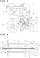
- the pleating section 2 has a front surface plate 10 and a back surface plate 11 (see FIG. 4 ) perpendicular to the base 1.
- the front surface plate 10 has an insertion hole 10a through which a distal portion of the balloon catheter 50 can be inserted.
- the back surface plate 11 has a back surface hole 11a (see FIG. 4 ) communicating with the insertion hole 10a.
- the pleating section 2 is provided with a first insertion assisting section 80 that assists insertion of the balloon catheter 50 into the insertion hole 10a.
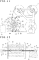
- the folding section 3 has a front surface plate 20 and a back surface plate 21 (see FIG. 12 ) perpendicular to the base 1.
- the front surface plate 20 has an insertion hole 20a through which the distal portion of the balloon catheter 50 can be inserted.
- the front surface plate 20 of the folding section 3 is oriented in a direction different by a predetermined angle from a direction in which the front surface plate 10 of the pleating section 2 is oriented.
- the back surface plate 11 has a back surface hole 21a (see FIG. 12 ) communicating with the insertion hole 20a.
- the folding section 3 is provided with a second insertion assisting section 90 that assists insertion of the balloon catheter 50 into the insertion hole 20a.
- a positioning section 1a capable of positioning the support base 4 to be oriented in two different directions is provided on the base 1.
- the support base 4 is positioned by the positioning section 1a in such a manner as to face the front surface plate 10 of the pleating section 2.
- the support base 4 can also be positioned in such a manner as to face the front surface plate 20 of the folding section 3.
- the support base 4 includes a base section 30 placed on the base 1, and a holding base section 31 which can be moved horizontally on the base section 30.
- the base section 30 includes a bottom surface portion 30a placed on an upper surface of the base 1 and positioned by the positioning section 1a, and a side surface portion 30b extending vertically upward from a side portion of the bottom surface portion 30a.
- a slide guide portion 30c for guiding the holding base section 31 is formed at an upper surface of the bottom surface portion 30a.
- the holding base section 31 is formed substantially in the shape of a rectangular parallelepiped which makes contact with the bottom surface portion 30a and the side surface portion 30b of the base section 30. A lower surface of the holding base section 31 is slidably guided by the slide guide portion 30c of the bottom surface portion 30a. Besides, an upper surface of the holding base section 31 has a groove-shaped placing portion 31a on which the shaft 51 of the balloon catheter 50 can be placed. Besides, the holding base section 31 is provided with a holding portion 31b such as to cover from above a part of the placing portion 31a. The holding portion 31b is capable of holding, and thereby fixing, the shaft 51 of the balloon catheter 50 placed on the placing portion 31a.
- the center of the insertion hole 10a formed in the front surface plate 10 and the center of the back surface hole 11a formed in the back surface plate 11 are located on an extension line of the placing portion 31a of the holding base section 31. Therefore, the balloon catheter 50 having the shaft 51 placed on the placing portion 31a is inserted into the pleating section 2 through the center position of the insertion hole 10a.
- the center of the insertion hole 20a formed in the front surface plate 20 and the center of the back surface hole 21a formed in the back surface plate 21 are located on an extension line of the placing portion 31a of the holding base section 31. For this reason, the balloon catheter 50 having the shaft 51 placed on the placing portion 31a is inserted into the folding section 3 through the center position of the insertion hole 20a.
- the pleating section 2 is provided therein with three blades 12.
- Each of the blades 12 is a plate-shaped member which is the same in sectional shape at each position along the axial direction of the balloon catheter 50 inserted.
- the blades 12 are disposed such that they are at an angle of 120° from one another, with the center position in regard of insertion of the balloon 52 as a reference. In other words, the blades 12 are disposed at regular angular intervals along the circumferential direction.
- the blade 12 has a rotational center portion 12a near an outer circumferential end portion thereof, and can be moved rotationally about the rotational center portion 12a.
- the blade 12 has a moving pin 12d extending in the axial direction, on the inner circumferential side of the rotational center portion 12a.
- the moving pin 12d is fitted in a fitting groove 14a formed in a rotary member 14 which is rotatable in the pleating section 2.
- the rotary member 14 is interlocked with a beam portion 16 extending substantially horizontally.
- the rotary member 14 is movable rotationally by receiving a rotating force from the beam portion 16 which is inclined by receiving a force from a drive source 15 such as a hydraulic cylinder or a motor.
- the blade 12 has a first shape forming portion 12b and a second shape forming portion 12c which are substantially arcuate in shape, at inner circumferential end portions on the side opposite to the rotational center portion 12a.
- the first shape forming portion 12b makes contact with the surface of the balloon 52 inserted in the pleating section 2, whereby the balloon 52 can be formed with a wing shape.
- the second shape forming portion 12c makes contact with the wing portion formed in the balloon 52, whereby the wing shape can be curved in a predetermined direction.
- the pleating section 2 has a heater (not depicted) for heating the blades 12. Note that the blades 12 may have a function of cooling.
- the blades 12 are supplied with the first film 45 and the second film 46 which are formed of resin, from the film supplying section 5.
- a plurality of rotary shaft portions 13 are provided in the pleating section 2.
- the first film 45 is supplied from a first film holding section 40 and through the rotary shaft portion 13 to be fed to a surface of the blade 12 disposed at an upper part.
- the first film 45 is fed through the blade 12 and the rotary shaft portion 13 to reach a film take-up section 42.
- the second film 46 is supplied from a second film holding section 41 and through the rotary shaft portion 13 to be fed to the two blades 12 disposed at lower parts.
- the second film 46 is fed through the rotary shaft portion 13 to reach the film take-up section 42.
- the first film 45 and the second film 46 have a protecting function for preventing direct contact of the balloon 52 with the surfaces of the blades 12 when the balloon 52 is inserted into the pleating section 2 and the blades 12 are moved rotationally to form the balloon 52 with wing shapes. After the wing shapes of the balloon 52 are formed, predetermined lengths of the first film 45 and the second film 46 are taken up by the film take-up section 42. In other words, the portions of the first film 45 and the second film 46 which portions have once made contact with the balloon 52 do not make contact with the balloon 52 again, and new portions of the films are supplied to the center position of the pleating section 2 every time the balloon 52 is inserted.
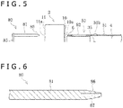
- the first insertion assisting section 80 includes an elongated assisting shaft 81, an interlock portion 82 interlocking the assisting shaft 81 with the support base 4, and support sections 83 supporting the interlock portion 82 in a slidable manner.
- the interlock portion 82 includes an elongated interlock shaft 84, and a fixing section 85 that fixes the assisting shaft 81 and the interlock shaft 84.
- the assisting shaft 81 holds the core metal member 6 inserted in the balloon catheter 50, and restrain the balloon catheter 50 from bending. Note that the assisting shaft 81 is also capable of holding the shaft 51 of the balloon catheter 50.
- the assisting shaft 81 is circular in sectional shape of an outer peripheral surface, and can enter the back surface hole 11a of the pleating section 2 and project to the exterior through the insertion hole 10a.
- the assisting shaft 81 has, on the side facing the back surface plate 11, a decreasing diameter portion 86 decreasing in outside diameter toward the back surface plate 11 in a tapered manner. An end portion of the assisting shaft 81 on the side opposite to the decreasing diameter portion 86 is interlocked with the fixing section 85 extending in a direction orthogonal to the assisting shaft 81.
- the decreasing diameter portion 86 of the assisting shaft 81 is formed therein with a cavity portion 87 opening at a distal end surface of the decreasing diameter portion 86.
- An axis of the cavity portion 87 coincides with the axis of the assisting shaft 81.
- the core metal member 6 can be inserted into the cavity portion 87 through the opening. With the core metal member 6 inserted in the cavity portion 87, the core metal member 6 is supported by the assisting shaft 81. This makes it possible to insert a distal portion of the balloon catheter 50 between the first film 45 and the second film 46 which two films are located between the blades 12, while restraining bending of the balloon catheter 50 by the assisting shaft 81 and the core metal member 6.
- An outside diameter of the assisting shaft 81 is greater than the outside diameter of the balloon 52 before wrapping of the balloon catheter 50 held. This makes it possible to restrain the balloon 52 from making contact with the first film 45 and the second film 46, at the time of inserting the balloon 52 between the first film 45 and the second film 46. This makes is possible to restrain a drug on a surface of the balloon 52 from dropping off due to contact with the first film 45 or the second film 46.
- the length of the assisting shaft 81 from the fixing section 85 to the distal end of the decreasing diameter portion 86 is preferably greater than the length in the extending direction of the blades 12 along the balloon catheter 50. This ensures that after the assisting shaft 81 passed through the blades 12 is caused to hold the core metal member 6, the assisting shaft 81 can be drawn out from between the blades 12 by retreating the assisting shaft 81. This permits the balloon 52 to be appropriately disposed between the plurality of blades 12.
- the length of the assisting shaft 81 from the fixing section 85 to the distal end of the decreasing diameter portion 86 is more preferably greater than the length from the insertion hole 10a to the back surface hole 11a. This permits the assisting shaft 81 to reach from the back surface hole 11a to the insertion hole 10a, and to be completely drawn out from the back surface hole 11a.
- the interlock shaft 84 is parallel to the assisting shaft 81, and part thereof penetrates the pleating section 2. Note that the interlock shaft 84 may not penetrate the pleating section 2.
- One end of the interlock shaft 84 is fixed to the assisting shaft 81 by the fixing section 85.
- the other end of the interlock shaft 84 can be interlocked with a holding base section 31 of the support base 4.
- the interlock shaft 84 by being interlocked with the holding base section 31, can be moved together with the holding base section 31.
- the assisting shaft 81 also is moved together with the holding base section 31.
- the holding base section 31 holding the shaft 51 on the proximal side relative to the balloon 50 of the balloon catheter 50 is moved along the axial direction of the balloon catheter 50, the assisting shaft 81 supporting a distal portion of the balloon catheter 50 is thereby also moved together with the holding base section 31. For this reason, the balloon catheter 50 can be restrained from bending at the time of inserting the balloon catheter 50 into the pleating section 2.
- the sectional shape of an outer peripheral surface of the interlock shaft 84 is not particularly limited, and is, for example, a rectangle. This ensures that the interlock shaft 84 is supported in a slidable but non-rotatable manner in relation to the support sections 83.
- the support sections 83 are disposed on the base 1, and each have a support hole 83a penetrating the interlock shaft 84.
- the support sections 83 support the interlock shaft 84 in a slidable manner.
- the number of the support sections 83 is not particularly limited.
- the holding base section 31 is provided with a holding base side interlock portion 33 to which an end portion of the interlock shaft 84 can be interlocked.
- the holding base side interlock portion 33 has an accommodation hole 34 that accommodates a distal portion of the interlock shaft 84.
- the holding base side interlock portion 33 has a fixing screw 35 screwed into the inside of the accommodation hole 34 from a lateral side. With the fixing screw 35 screwed in in a state in which the interlock shaft 84 is accommodated in the accommodation hole 34, the interlock shaft 84 can be fixed to the holding base section 31. Note that the method for interlocking the interlock shaft 84 and the holding base section 31 is not limited to the fixing screw 35.
- the holding base side interlock portion may be a part against which the distal portion of the interlock shaft 84 can only butts.
- the interlock shaft 84 is moved by being pushed by the holding base side interlock portion when the holding base section 31 is moved toward the pleating section 2.
- the interlocked state at the time of movement can be maintained.
- the shaft 51 includes a hollow outer tube 53, and a hollow inner tube 54.
- the inner tube 54 is accommodated in a hollow inside of the outer tube 53, and the shaft 51 is of a double-tube structure at the distal portion thereof.
- the hollow inside of the inner tube 54 forms a guide wire lumen 58 in and through which a guide wire 57 is inserted and passed.
- an inflation lumen 59 in which an inflation fluid for the balloon 52 flows is formed in the hollow inside of the outer tube 53 and on the outside of the inner tube 54.
- the inner tube 54 is open to the exterior at an opening portion 55.
- the inner tube 54 protrudes to the distal side beyond a distal end of the outer tube 53.
- the balloon 52 has a proximal-side end portion fixed to a distal portion of the outer tube 53, and has a distal-side end portion fixed to a distal portion of the inner tube 54.
- the balloon 52 can be inflated by injecting an inflation fluid into the balloon 52 through the inflation lumen 59.
- the inflation fluid may be either a gas or a liquid; for example, a gas such as helium gas, CO 2 gas and O 2 gas or a liquid such as a saline solution and a contrast medium can be used as the inflation fluid.
- the outer tube 53 and the inner tube 54 are preferably formed from a material that has a certain degree of flexibility.
- a material that has a certain degree of flexibility.
- examples of such a material include polyolefins such as polyethylene, polypropylene, polybutene, ethylene-propylene copolymer, ethylene-vinyl acetate copolymer, ionomers, or mixtures of two or more of them, flexible polyvinyl chloride resin, polyamides, polyamide elastomers, polyesters, polyester elastomers, polyurethane, fluoro-resin such as polytetrafluoroethylene, silicone rubbers and latex rubbers.
- the balloon catheter 50 to be inserted into the pleating section 2 has the shaft 51 placed on a placing portion 31a of the support base 4, and held and fixed by the holding portion 31b.
- the shaft 51 is disposed in such a manner that the opening portion 55 is located on the proximal side relative to the holding portion 31b.
- the core metal member 6 inserted in and passed through the guide wire lumen 58 is provided on the distal side relative to the opening portion 55.
- the core metal member 6 is formed in a thin elongated wire-like shape or a hollow shape from a metallic material.
- a metallic material for forming the core metal member 6 there is selected a material having such a degree of hardness that a distal portion of the shaft 51 inclusive of the balloon 52 will not bend due to its own weight where the core metal member 6 is inserted in the balloon 52 and the shaft 51.
- the metallic material for forming the core metal member 6 is not specifically restricted, and examples thereof include stainless steel, Ni-Ti alloys, tungsten, and hard metals.
- the core metal member 6 may be formed by annealing any of these metallic materials, for realizing a shape memory property.
- the core metal member 6 is formed in a substantially circular shape in section, and an outside diameter thereof is smaller than the inside diameter of the inner tube 54 by 0.01 to 0.1 mm. If the outside diameter of the core metal member 6 is smaller than the aforesaid appropriate value in relation to the inside diameter of the inner tube 54, the balloon 52 part cannot be held sufficiently by the core metal member 6 and bending of the balloon 52 would occur. As a result, the shaft 51 may be distorted when the balloon 52 is formed with wing shapes by the pleating section 2. In addition, if the outside shape of the core metal member 6 is greater than the aforesaid appropriate value in relation to the inside diameter of the inner tube 54, the core metal member 6 may interfere with the inner surface of the inner tube 54, possibly breaking the inner tube. With the outside diameter of the core metal member 6 set as above-mentioned, these problems can be prevented from occurring.
- the core metal member 6 has such a length as to extend from the distal side relative to the distal end of the balloon 52 to the proximal side relative to the opening portion 55 of the shaft 51. Since the opening portion 55 is located on the proximal side relative to the holding portion 31b of the support base 4, the core metal member 6 also is held by the holding portion 31b at the position where the shaft 51 is held by the holding portion 31b. In other words, the core metal member 6 is held by the assisting shaft 81 on the distal side, and by the holding portion 31b of the support base 4 on the proximal side, whereby the shaft 51 can be more effectively restrained from bending due to its own weight.
- the shaft 51 is restrained from bending due to its own weight, with respect to the distal side relative to its portion supported by the support base 4.
- the balloon 52 With the balloon 52 accurately positioned in relation to, and inserted into, the pleating section 2, the balloon 52 can be formed with the wing shapes accurately, and the wing shapes can be made uniform in the circumferential direction.
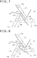
- first shape forming portions 12b and second shape forming portions 12c of the three blades 12 are in a mutually space-apart state.
- a central region between the blades 12 is surrounded by the first shape forming portions 12b which are substantially arcuate in shape.
- the assisting shaft 81 is not inserted in the back surface hole 11a of the back surface plate 11.
- the shaft 51 of the balloon catheter 50 is mounted to the holding base section 31 of the support base 4.
- the inflation fluid is injected into the balloon 52 through a hub 56 and the inner tube 54, putting the balloon 52 into a somewhat inflated state.
- the assisting shaft 81 is inserted into the back surface hole 11a of the pleating section 2, and is protruded to the exterior through the insertion hole 10a.
- the interlock shaft 84 slides on the support sections 83, and its distal portion butts against the holding base side interlock portion 33.
- the decreasing diameter portion 86 is formed at the distal portion of the assisting shaft 81, the decreasing diameter portion 86 can easily pass between the first film 45 and the second film 46. Therefore, the assisting shaft 81 can protrude to the exterior through the insertion hole 10a, without damaging the first film 45 or the second film 46.
- the distal portion of the core metal member 6 protruding from the balloon catheter 50 is inserted into the cavity portion 87 of the assisting shaft 81. This puts the core metal member 6 into a state in which its distal portion is held by the assisting shaft 81. Subsequently, in a state in which the distal portion of the interlock shaft 84 is inserted in the accommodation hole 34 of the holding base side interlock portion 33, the fixing screw 35 is screwed in. By this, the interlock shaft 84 is interlocked with the holding base section 31.
- the holding base section 31 is moved toward the pleating section 2.
- the interlock shaft 84 is interlocked with the holding base section 31, the assisting shaft 81 also is moved together with the holding base section 31.
- the balloon catheter 50 can be restrained from bending when the balloon catheter 50 is inserted into the pleating section 2. Therefore, the balloon 52 can be accurately positioned at a center position of the pleating section 2. Accordingly, the wing shapes of the balloon 52 can be formed uniformly in the circumferential direction.
- the outside diameter of the assisting shaft 81 is greater than the outside diameter of the balloon 52, the balloon 52 can be restrained from making contact with the first film 45 or the second film 46.
- the drug can be restrained from dropping off the balloon 52.
- the assisting shaft 81 reaches the exterior of the pleating section 2 by passing through the back surface hole 11a, the balloon 52 is located in the central region between the blades 12. Subsequently, the heated blades 12 of the pleating section 2 are rotated, whereby the balloon 52 is formed with the wing shapes.
- the first shape forming portions 12b of the blades 12 come closer to one another, and the central region between the blades 12 is narrowed, as depicted in FIG. 9 .
- the balloon 52 inserted in the central region between the blades 12 is pressed against the inner tube 54 by the first shape forming portions 12b.
- a portion of the balloon 52 which portion is not pressed by the first shape forming portion 12b is pushed out into a gap between a distal portion of one blade 12 and the second shape forming portion 12c of the blade 12 adjacent to the one blade 12, whereby a wing shape curved to one side is formed.
- the balloon 52 is heated by the blades 12, the wing shapes thus formed can be maintained in their shape. In this way, the balloon 52 is formed with three wing shapes in the circumferential direction. In the case where a surface of the balloon 52 is provided thereon with a coating which is low in resistance to heat, the blades 12 may not be heated, or may be cooled.
- the holding base section 31 is moved, and the balloon 52 is drawn out of the pleating section 2.
- the assisting shaft 81 since the interlock shaft 84 is interlocked with the holding base section 31, the assisting shaft 81 also is moved together with the holding base section 31. Therefore, bending of the balloon catheter 50 can be restrained by the assisting shaft 81 and the core metal member 6. Consequently, the balloon 52 can be restrained from making contact with the insertion hole 10a or the like in the pleating section 2, and the drug can be restrained from dropping off.
- the fixing screw 35 at the holding base side interlock portion 33 is loosened, to release the interlock between the holding base section 31 and the interlock shaft 84.
- the assisting shaft 81 is moved, to be drawn out from the back surface hole 11a of the pleating section 2.
- the core metal member 6 is drawn out of the cavity portion 87 of the assisting shaft 81.
- the support base 4 can be moved on the base 1, and the holding base section 31 is oriented toward the folding section 3.
- the interlock between the holding base section 31 and the interlock shaft 84 may be released before drawing the balloon 52 out of the pleating section 2.
- the balloon catheter 50 is drawn out of the pleating section 2, while being restrained by the core metal member 6 from bending.
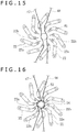
- the folding section 3 is provided therein with ten blades 22.
- Each of the blades 22 is a plate-shaped member formed to be the same in sectional shape at each position along the axial direction of the balloon catheter 50 to be inserted.
- the blades 22 are disposed such that they are at an angle of 36° from one another, with the center position in regard of insertion of the balloon as a reference. In other words, the blades 22 are disposed at regular angular intervals along the circumferential direction.
- the blade 22 has a rotational center portion 22a near an outer circumferential end portion thereof, and can be moved rotationally about the rotational center portion 22a.
- the blade 22 has a moving pin 22c extending in the axial direction, near a substantially outer circumferential end portion thereof.
- the moving pin 22c is fitted in a fitting groove 23a formed in a rotary member 23 which is rotatable in the folding section 3.
- the rotary member 23 is interlocked with a beam portion 25 extending substantially horizontally.
- the rotary member 23 is movable rotationally by receiving a rotating force from the beam portion 25 which is inclined by receiving a force from a drive source 24 such as a hydraulic cylinder or a motor.
- a drive source 24 such as a hydraulic cylinder or a motor.
- the blade 22 is bent on the distal side, and has a distal portion 22b in a pointing shape. Attendant on rotary movement of the blade 22, the distal portion 22b makes contact with a surface of the balloon 52 inserted in the folding section 3, whereby the wing shape formed in the balloon 52 can be folded in the manner of winding the wing shapes around the inner tube 54.
- the folding section 3 has a heater (not depicted) for heating the blades 22. Note that the blades 22 may have a function of cooling.
- the blades 22 are supplied with a first film 47 and a second film 48 from a film supplying section 8.
- the film supplying structure is the same as in the case of the pleating section 2.
- the first film 47 and the second film 48 are disposed opposite to each other in such a manner as to sandwich a central space region surrounded by the blades 22.
- the folding section 3 is provided with the second insertion assisting section 90 that assists insertion of the balloon catheter 50 into the insertion hole 20a.
- the second insertion assisting section 90 is similar in structure to the first insertion assisting section 80. Therefore, component members of the second insertion assisting section 90 are denoted by similar reference symbols to those for the first insertion assisting section 80, and descriptions of them will be omitted.
- the assisting shaft 81 of the second insertion assisting section 90 can enter the folding section 3 via the back surface hole 21a and can protrude to the exterior through the insertion hole 20a.
- the outside diameter of the assisting shaft 81 is greater than the outside diameter after pleating of the balloon 52 of the balloon catheter 50 held. This ensures that the balloon 52 is restrained from making contact with the first film 47 or the second film 48 when the balloon 52 is inserted between the first film 47 and the second film 48. As a result, the drug on the surface of the balloon 52 can be restrained from dropping off due to contact with the first film 47 or the second film 48.
- the length from the assisting shaft 81 from the fixing section 85 to the distal portion is preferably greater than the extending length of the blades 22 along the balloon catheter 50. This ensures that after the core metal member 6 is held by the assisting shaft 81 passed through the blades 22, the assisting shaft 81 can be retreated and thereby drawn out from between the blades 22. As a result, the balloon 52 can be suitably disposed between the plurality of blades 22.
- the length of the assisting shaft 81 from the fixing section 85 to the distal end of the decreasing diameter portion 86 is more preferably greater than the length from the insertion hole 20a to the back surface hole 21a. This permits the assisting shaft 81 to reach from the back surface hole 21a to the insertion hole 20a, and to be completely drawn out from the back surface hole 21a.
- the folding of the balloon 52 in the folding section 3 will be described.
- the balloon catheter 50 is directed toward the folding section 3 together with the holding base section 31 by a movement of the support base 4.
- the shaft 51 of the balloon catheter 50 is in a state of being held by the holding portion 31b of the support base 4.
- the core metal member 6 is inserted in and passed through the balloon 52.
- the distal portions 22b of the blades 22 are mutually spaced apart in the circumferential direction.
- the balloon 52 formed with the wing shapes can be inserted into a central region surrounded by the blades 22 and between the first film 47 and the second film 48.
- the assisting shaft 81 is not inserted in the back surface hole 21a of the back surface plate 21.
- the assisting shaft 81 is inserted into the back surface hole 21a of the folding section 3, and is protruded to the exterior through the insertion hole 20a.
- the interlock shaft 84 slides on the support section 83, and its distal portion butts against the holding base side interlock portion 33.
- the decreasing diameter portion 86 is formed at the distal portion of the assisting shaft 81, the decreasing diameter portion 86 can easily pass between the first film 47 and the second film 48. Therefore, the assisting shaft 81 can protrude to the exterior through the insertion hole 20a, without damaging the first film 47 or the second film 48.
- the holding base section 31 is moved toward the folding section 3.
- the assisting shaft 81 since the interlock shaft 84 is interlocked with the holding base section 31, the assisting shaft 81 also is moved together with the holding base section 31.
- the balloon catheter 50 can be restrained from being when the balloon catheter 50 is inserted into the folding section 3. Therefore, the balloon 52 can be accurately positioned at the center position of the folding section 3.
- the outside diameter of the assisting shaft 81 is greater than the outside diameter of the balloon 52, the balloon 52 can be restrained from making contact with the first film 47 or the second film 48. Consequently, the drug can be restrained from dropping off the balloon 52.
- the assisting shaft 81 reaches the exterior of the folding section 3 by passing through the back surface hole 21a, the balloon 52 is located in the central region between the blades 22.
- the folding section 3 is moved rotationally.
- the distal portions 22b of the blades 22 come closer to one another, and the central region between the blades 22 is narrowed.
- the balloon 52 inserted in the central region between the blades 22 is put into a state in which the wing shapes are laid flat in the circumferential direction by the distal portions 22b of the blades 22. Since the blades 22 are preliminarily heated before insertion of the balloon 52 and the balloon 52 is heated by the blades 22, the wing shapes laid flat in the circumferential direction by the blades 22 can be maintained in their shape. Note that the blades 22 may be preliminarily cooled.
- the surfaces of the blades 22 which surfaces make contact with the balloon 52 are covered with the first film 47 and the second film 48, so that the balloon 52 does not make direct contact with the surfaces of the blades 22. Since the balloon catheter 50 is restrained by the core metal member 6 and the assisting shaft 81 from bending, the balloon 52 is accurately positioned at the center position of the folding section 3. Therefore, generation of back folding at the time of folding the balloon 52 can be restrained. After the wing shapes of the balloon 52 are folded, the blades 22 are moved rotationally in the manner of being returned to their original positions.
- the holding base section 31 is moved, whereby the balloon 52 is withdrawn from the folding section 3.
- the assisting shaft 81 since the interlock shaft 84 is interlocked with the holding base section 31, the assisting shaft 81 also is moved together with the holding base section 31. Therefore, the balloon catheter 50 can be restrained by the assisting shaft 81 and the core metal member 6 from bending. Accordingly, the balloon 52 can be restrained from making contact with the insertion hole 20a or the like in the folding section 3, and the drug can be prevented from dropping off.
- the fixing screw 35 of the holding base side interlock portion 33 is untightened, to release the interlock between the holding base section 31 and the interlock shaft 84.
- the assisting shaft 81 is moved, to be withdrawn from the back surface hole 21a of the folding section 3.
- the wrapping of the balloon 52 by the balloon wrapping apparatus is completed.
- the interlock between the holding base section 31 and the interlock shaft 84 may be released before withdrawing the balloon 52 from the folding section 3.
- the balloon catheter 50 is withdrawn from the folding section 3 while being restrained by the core metal member 6 from bending.
- a balloon 62 of an over-the-wire type catheter can also be wrapped by the same balloon wrapping apparatus.
- this over-the-wire type balloon catheter 60 has a balloon 62 at a distal-side end portion of a shaft 61.
- the shaft 61 has a configuration in which, for the whole length on the proximal side relative to the balloon 62, an inner tube 64 is disposed in a hollow inside of an outer tube 63, and the outer tube 63 and the inner tube 64 extend to a hub (not depicted) provided at a proximal-side end portion of the shaft 61.
- the structure of the balloon 62 part is similar to that in the case of the rapid exchange type.
- the core metal member 70 is formed such that an intermediate portion is curved.
- the core metal member 70 is inserted into the rapid exchange type balloon catheter 50 drawn on the upper side.
- the core metal member 70 is curved in such a manner that when the core metal member 70 is inserted in the balloon catheter 50, a part located in the shaft 51 is projected to the upper side.
- the core metal member 70 has a flat surface portion 70a at part of a circumferential surface.
- the core metal member 70 in the present mode has its distal portion fixed to the assisting shaft 100, like in the aforementioned embodiment. That part of the assisting shaft 100 which fixes the core metal member 70 has a flat surface portion 101 corresponding to the flat surface portion 70a, and the core metal member 70 can be fixed in only a predetermined orientation in relation to the assisting shaft 100. This permits the core metal member 70 inserted in the shaft 51 to be in a predetermined orientation, specifically, an orientation in which the curved portion is projected to the upper side.
- the core metal member 70 has a curvature corresponding to an amount of bending at a distal portion of the shaft 51 due to its own weight. Therefore, in a state in which the core metal member 70 is inserted in the shaft 51, the downward bending of the shaft 51 due to its own weight and the upward curvature of the core metal member 70 cancel each other, whereby the shaft 51 is put in a more horizontal state.
- forming the core metal member in a curved shape is not limited to the case of the rapid exchange type balloon catheter 50, but may be applied also to the over-the-wire type balloon catheter 60.
- a cavity portion 111 of the assisting shaft 110 in the present mode is formed in a hollow inner surface member 112 formed from a material having a high frictional coefficient.
- the material having a high frictional coefficient is higher in static frictional coefficient and dynamic frictional coefficient than a shaft main body 114 of the assisting shaft 110 into which the inner surface member 112 is fitted. Examples of the material having a high frictional coefficient include silicone rubbers, latex rubbers and natural rubber.
- the inner surface member 112 may be an elastic material capable of elastic deformation. This ensures that the core metal member 6 or the shaft 51 of the balloon catheter 50 inserted into the cavity portion 111 can be held in the manner of being sandwiched by the inner surface member 112 which is elastically deformed.
- the elastic material include silicone rubbers, latex rubbers and natural rubber.
- the cavity portion 111 of the assisting shaft 110 may decrease in inside diameter toward the depth side. This ensures that by pushing the core metal member 6 or the shaft 51 of the balloon catheter 50 into the cavity portion 111, the shaft 51 can be highly accurately positioned at the center of the assisting shaft 110, and can be favorably held by being sandwiched by the cavity portion 111. Therefore, the wing shapes of the balloon 52 can be formed uniformly in the circumferential direction in the pleating section 2, and generation of back folding can be restrained at the time of folding the wing shapes in the folding section 3.
- the assisting shaft may have a mechanism for clamping and fixing the core metal member 6.
- the mechanism for clamping and fixing the core metal member 6 include a collet chuck, a scroll chuck, a drill chuck, and an independent chuck.
- the support base that supports the balloon catheter 50 may have a structure of being capable of rotation around an axis of the balloon catheter 50 in a state of holding the balloon catheter 50. In this case, by rotating the balloon catheter 50 in a direction reverse to a folding direction at the time of folding the wing shapes of the balloon 52 in the folding section 3, an effect of restraining back folding can be further enhanced.
- the balloon wrapping apparatus is a balloon wrapping apparatus for wrapping the balloon 52 provided at a distal portion of the elongated shaft 51, and includes: the pleating section 2 for forming the balloon 52 with the wing shapes; the folding section 3 for folding the wing shapes formed in the balloon 52, along the circumferential direction; and the support base 4 that supports the shaft 51, can be moved closer to and away from at least one of the pleating section 2 and the folding section 3, and causes the balloon 52 to be insertable into the pleating section 2 and the folding section 3.
- the pleating section 2 and the folding section 3 include the insertion holes 10a and 20a into which the balloon 52 can be inserted, and the back surface holes 11a and 21a that are provided in the back surfaces on the sides opposite to the sides where the insertion holes 10a and 20a are provided and that communicate with the insertion holes 10a and 20a.
- the pleating section 2 and the folding section 3 include: the assisting shaft 81 that can be inserted into the back surface holes 11a and 21a from the back surface side; and the interlock portion 82 interlocking a part of the assisting shaft 81 which part is not inserted in the back surface hole 11a or 21a with the support base 4 in such a manner that the assisting shaft 81 can be moved together with the support base 4.
- the assisting shaft 81 is formed with the cavity portion 87 from the side of facing the back surface hole 11a or 21a.
- the balloon wrapping apparatus configured as above-mentioned has a configuration in which by inserting the assisting shaft 81 into the back surface hole 11a or 21a and causing the assisting shaft 81 to reach the insertion hole 10a or 20a, the core meal member 6 inserted in the shaft 51 can be inserted in and held by the cavity portion 87 of the assisting shaft 81.
- the assisting shaft 81 is interlocked with the support base 4 by the interlock portion 82, the assisting shaft 81 is moved together with the support base 4, and, therefore, the balloon 52 can be inserted into the insertion hole 10a or 20a while maintaining the state in which the balloon 52 is held by the assisting shaft 81.
- This ensures that the distal portion of the shaft 51 of the balloon catheter 50 is supported by the assisting shaft 81 in such a manner as not to bend, and, therefore, the balloon 52 can be accurately positioned in relation to and inserted into the pleating section 2 and the folding section 3.
- the wing shapes of the balloon 52 can be formed uniformly in the circumferential direction in the pleating section 2, and generation of back folding can be restrained at the time of folding the wing shapes in the folding section 3.
- the balloon wrapping apparatus further includes the core metal member 6 to be inserted in the shaft 51, and the core metal member 6 can be inserted into the cavity portion 87 of the assisting shaft 81.
- At least one of the pleating section 2 and the folding section 3 includes the plurality of blades 12, 22 aligned in the circumferential direction for giving a shape to the balloon 52, and the two films passing through a central portion surrounded by the plurality of blades 12, 22.
- the assisting shaft 81 has the decreasing diameter portion 86 decreasing in outside diameter toward the back surface hole 11a, 21a. This permits the decreasing diameter portion 86 of the assisting shaft 81 to smoothly pass between the two films.
- the blades 12, 22 extend in a direction from the insertion hole 10a, 20a toward the back surface hole 11a, 21a, and the direction in which the assisting shaft 81 can be moved together with the support base 4 is parallel to the extending direction of the blades 12, 22.
- the wing shapes of the balloon 52 can be formed uniformly in the circumferential direction in the pleating section 2, and generation of back folding can be restrained at the time of folding the wing shapes in the folding section 3.
- the maximum diameter of the assisting shaft 81 is greater than the diameter of the balloon 52. This ensures that when the balloon 52 held by the assisting shaft 81 is moved in the axial direction together with the assisting shaft 81, the balloon 52 can be restrained from making contact with other member. Therefore, the drug on the surface of the balloon 52 can be restrained from dropping off.
- the core metal member 6 is longer than the length in the extending direction of the blades by not less than 10 mm. This permits the core metal member 6 to be placed on both the assisting shaft 81 and the support base 4, and the shaft 51 of the balloon catheter 50 can be securely supported and restrained from bending.
- Example 1 Example 2
- Example 3 Example 4
- Example 5 Diameter/length of balloon 2.0 mm/40 mm 4.0 mm/200 mm 3.0 mm/200 mm 2.0 mm/200 mm 6.0 mm/200 mm
- Amount of paclitaxel 3.2 ⁇ g/mm 2 3.6 ⁇ g/mm 2 3.6 ⁇ g/mm 2 3.2 ⁇ g/mm 2 3.2 ⁇ g/mm 2 3.2 ⁇ g/mm 2
- Diameter/length of core metal member 0.39 mm/700 mm 0.38 mm/500
- a coating liquid was prepared by dissolving L-serine ethyl ester hydrochloride (CAS No.: 26348-61-8) and paclitaxel (CAS No.: 33069-62-4) in a mixed liquid of anhydrous ethanol, tetrahydrofuran, acetone and distilled water.
- a three-way cock was attached to a hub portion of a balloon catheter (material of balloon: nylon, the surface being smooth and non-porous) 2.0 mm in diameter and 40 mm in length when inflated, the balloon was inflated at 4 atm, and coating with the coating liquid was slowly conducted such that the amount of paclitaxel on the balloon would be approximately 3.2 ⁇ g/mm 2 . After the coating, the balloon catheter was dried, to produce a drug-coated balloon.
- a core metal member (material: SUS) in the form of wire (solid) 0.39 mm in diameter and 700 mm in length was inserted into a guide wire lumen (0.014 inch specification: 0.40 to 0.44 mm) of the dried drug-coated balloon, the balloon catheter was placed on a support base of a balloon wrapping apparatus such that the drug coating portion did not make contact with the support base, and a shaft of the balloon catheter was fixed to a holding base section by a holding portion fitted with silicone rubber.
- a guide wire lumen (0.014 inch specification: 0.40 to 0.44 mm) means a guide wire lumen for passing therethrough and using a guide wire having a diameter of 0.014 inch, the diameter (inside diameter) of the guide wire lumen being 0.40 to 0.44 mm (the same applies hereinafter).
- the three-way cock of the hub of the balloon catheter was attached to an air injection and suction mechanism for inflating and deflating the balloon of the wrapping apparatus.
- the core metal member protruding from a distal portion of the balloon catheter was inserted into a distal support (assisting shaft) of a pleating section 2.
- the balloon was pushed in between a first film and a second film (material: PTFE, thickness: 0.001 mm) which are difficult to electrostatically charge and smooth and which were passed between blades of the pleating section having three blades.
- a first film and a second film material: PTFE, thickness: 0.001 mm
- the heated blades were slowly closed simultaneously with starting of pleating, to press the blades against the balloon, and air inside the balloon was slowly sucked to deflate the balloon.
- the blades were held in the closed state for a while, to form wings, and then the blades were slowly opened, to spread the films. Thereafter, the balloon was drawn back from the pleating section.
- the support base was slid to a folding section.
- the core metal member protruding from the distal portion of the balloon catheter was inserted into a distal support (assisting shaft) of the folding section, and the balloon portion was pushed in between a first film and a second film (material: PTFE, thickness: 0.001 mm) which are difficult to electrostatically charge and smooth and which were passed between blades of the folding section having ten blades.
- the heated blades were slowly closed, then, from the point of time when the first film and the second film were made contact with the wings, the balloon catheter was slowly rotated in the direction reverse to the rotary movement direction of the blades, and the rotation of the balloon was finished before the blades were closed completely.
- the ten blades were held in a closed state for a while, after which the blades were slowly opened, to spread the first film and the second film. Thereafter, the balloon was drawn back from the folding section.
- a coating liquid was prepared by dissolving L-serine ethyl ester hydrochloride (CAS No.: 26348-61-8) and paclitaxel (CAS No.: 33069-62-4) in a mixed liquid of anhydrous ethanol, tetrahydrofuran, acetone and distilled water.
- a three-way cock was attached to a hub portion of a balloon catheter (material of balloon: nylon, the surface being smooth and non-porous) 4.0 mm in diameter and 200 mm in length when inflated, the balloon was inflated at 4 atm, and coating with the coating liquid was slowly conducted such that the amount of paclitaxel on the balloon would be approximately 3.6 ⁇ g/mm 2 . After the coating, the balloon catheter was dried, to produce a drug-coated balloon.
- a core metal member (material: SUS) in the form of wire 0.38 mm in diameter and 500 mm in length was inserted into a guide wire lumen (0.014 inch specification: 0.40 to 0.44 mm) of the dried drug-coated balloon, the balloon catheter was placed on a support base of a balloon wrapping apparatus such that the drug coating portion did not make contact with the support base, and a shaft of the balloon catheter was fixed to the holding base section by the holding portion fitted with silicone rubber.
- the three-way cock of the hub of the balloon catheter was attached to the air injection and suction mechanism for inflating and deflating the balloon of the wrapping apparatus.
- the core metal member protruding from a distal portion of the balloon catheter was inserted into the distal support (assisting shaft) of the pleating section.
- the balloon was pushed in between a first film and a second film (material: PTFE, thickness: 0.001 mm) which are difficult to electrostatically charge and smooth and which were passed between blades of the pleating section having three blades.
- the heated blades were slowly closed simultaneously with starting of pleating, to press the blades against the balloon, and air inside the balloon was slowly sucked to deflate the balloon.
- the blades were held in the closed state for a while, to form wings, and then the blades were slowly opened, to spread the films. Thereafter, the balloon was drawn back from the pleating section.
- the support base was slid to the folding section.
- the core metal member protruding from the distal portion of the balloon catheter was inserted into the distal support (assisting shaft) of the folding section, and the balloon portion was pushed in between a first film and a second film (material: PTFE, thickness: 0.001 mm) which are difficult to electrostatically charge and smooth and which were passed between blades of the folding section having ten blades.
- the heated blades were slowly closed.
- the ten blades were held in a closed state for a while, after which the blades were slowly opened, to spread the first film and the second film. Thereafter, the balloon was drawn back from the folding section.
- a coating liquid was prepared by dissolving L-serine ethyl ester hydrochloride (CAS No.: 26348-61-8) and paclitaxel (CAS No.: 33069-62-4) in a mixed liquid of anhydrous ethanol, tetrahydrofuran, acetone and distilled water.
- a three-way cock was attached to a hub portion of a balloon catheter (material of balloon: nylon, the surface being smooth and non-porous) 3.0 mm in diameter and 200 mm in length when inflated, the balloon was inflated at 4 atm, and coating with the coating liquid was slowly conducted such that the amount of paclitaxel on the balloon would be approximately 3.6 ⁇ g/mm 2 . After the coating, the balloon catheter was dried, to produce a drug-coated balloon.
- a core metal member (material: SUS) in the form of wire 0.38 mm in diameter and 500 mm in length was inserted into a guide wire lumen (0.014 inch specification: 0.40 to 0.44 mm) of the dried drug-coated balloon, the balloon catheter was placed on the support base of the balloon wrapping apparatus such that the drug coating portion did not make contact with the support base, and a shaft of the balloon catheter was fixed to the holding base section by the holding portion fitted with silicone rubber.
- the three-way cock of the hub of the balloon catheter was attached to the air injection and suction mechanism for inflating and deflating the balloon of the wrapping apparatus.
- the core metal member protruding from a distal portion of the balloon catheter was inserted into the distal support (assisting shaft) of the pleating section.
- the balloon was pushed in between a first film and a second film (material: PTFE, thickness: 0.001 mm) which are difficult to electrostatically charge and smooth and which were passed between blades of the pleating section having three blades.
- a first film and a second film material: PTFE, thickness: 0.001 mm
- the heated blades were slowly closed simultaneously with starting of pleating, to press the blades against the balloon, and air inside the balloon was slowly sucked to deflate the balloon.
- the blades were held in the closed state for a while, to form wings, and then the blades were slowly opened, to spread the films. Thereafter, the balloon was drawn back from the pleating section.
- the support base was slid to the folding section.
- the core metal member protruding from the distal portion of the balloon catheter was inserted into the distal support (assisting shaft) of the folding section, and the balloon portion was pushed in between a first film and a second film (material: PTFE, thickness: 0.001 mm) which are difficult to electrostatically charge and smooth and which were passed between blades of the folding section having ten blades.
- the heated blades were slowly closed.
- the ten blades were held in a closed state for a while, after which the blades were slowly opened, to spread the first film and the second film. Thereafter, the balloon was drawn back from the folding section.
- a coating liquid was prepared by dissolving L-serine ethyl ester hydrochloride (CAS No.: 26348-61-8) and paclitaxel (CAS No.: 33069-62-4) in a mixed liquid of anhydrous ethanol, tetrahydrofuran, acetone and distilled water.
- a three-way cock was attached to a hub portion of a balloon catheter (material of balloon: nylon, the surface being smooth and non-porous) 2.0 mm in diameter and 200 mm in length when inflated, the balloon was inflated at 4 atm, and coating with the coating liquid was slowly conducted such that the amount of paclitaxel on the balloon would be approximately 3.2 ⁇ g/mm 2 . After the coating, the balloon catheter was dried, to produce a drug-coated balloon.
- a core metal member (material: SUS) in the form of wire 0.38 mm in diameter and 700 mm in length was inserted into a guide wire lumen (0.014 inch specification: 0.40 to 0.44 mm) of the dried drug-coated balloon, the balloon catheter was placed on the support base of the balloon wrapping apparatus such that the drug coating portion did not make contact with the support base, and a shaft of the balloon catheter was fixed to the holding base section by the holding portion fitted with silicone rubber.
- the three-way cock of the hub of the balloon catheter was attached to the air injection and suction mechanism for inflating and deflating the balloon of the wrapping apparatus.
- the core metal member protruding from a distal portion of the balloon catheter was inserted into the distal support (assisting shaft) of the pleating section.
- the balloon was pushed in between a first film and a second film (material: PTFE, thickness: 0.001 mm) which are difficult to electrostatically charge and smooth and which were passed between blades of the pleating section having three blades.
- a first film and a second film material: PTFE, thickness: 0.001 mm
- the heated blades were slowly closed simultaneously with starting of pleating, to press the blades against the balloon, and air inside the balloon was slowly sucked to deflate the balloon.
- the blades were held in the closed state for a while, to form wings, and then the blades were slowly opened, to spread the films. Thereafter, the balloon was drawn back from the pleating section.
- the support base was slid to a folding section.
- the core metal member protruding from the distal portion of the balloon catheter was inserted into a distal support (assisting shaft) of the folding section, and the balloon portion was pushed in between a first film and a second film (material: PTFE, thickness: 0.001 mm) which are difficult to electrostatically charge and smooth and which were passed between blades of the folding section having ten blades.
- the heated blades were slowly closed, then, from the point of time when the first film and the second film made contact with the wings, the balloon catheter was slowly rotated in the direction reverse to the rotary movement direction of the blades, and the rotation of the balloon was finished before the blades were closed completely.
- the ten blades were held in a closed state for a while, after which the blades were slowly opened, to spread the first film and the second film. Thereafter, the balloon was drawn back from the folding section.
- a coating liquid was prepared by dissolving L-serine ethyl ester hydrochloride (CAS No.: 26348-61-8) and paclitaxel (CAS No.: 33069-62-4) in a mixed liquid of anhydrous ethanol, tetrahydrofuran, acetone and distilled water.
- a three-way cock was attached to a hub portion of a balloon catheter (material of balloon: nylon, the surface being smooth and non-porous) 6.0 mm in diameter and 200 mm in length when inflated, the balloon was inflated at 4 atm, and coating with the coating liquid was slowly conducted such that the amount of paclitaxel on the balloon would be approximately 3.2 ⁇ g/mm 2 . After the coating, the balloon catheter was dried, to produce a drug-coated balloon.
- a core metal member (material: SUS) in the form of wire 0.48 mm in diameter and 700 mm in length was inserted into a guide wire lumen (0.018 inch specification: 0.50 to 0.54 mm) of the dried drug-coated balloon, the balloon catheter was placed on the support base of the balloon wrapping apparatus such that the drug coating portion did not make contact with the support base, and a shaft of the balloon catheter was fixed to the holding base section by the holding portion fitted with silicone rubber.
- a guide wire lumen (0.018 inch specification: 0.50 to 0.54 mm) means a guide wire lumen for passing therethrough and using a guide wire having a diameter of 0.018 inch, the diameter (inside diameter) of the guide wire lumen being 0.50 to 0.54 mm (the same applies hereinafter).
- the three-way cock of the hub of the balloon catheter was attached to the air injection and suction mechanism for inflating and deflating the balloon of the wrapping apparatus.
- the core metal member protruding from a distal portion of the balloon catheter was inserted into the distal support (assisting shaft) of the pleating section.
- the balloon was pushed in between a first film and a second film (material: PTFE, thickness: 0.001 mm) which are difficult to electrostatically charge and smooth and which were passed between blades of the pleating section having four blades.
- the heated blades were slowly closed simultaneously with starting of pleating, to press the blades against the balloon, and air inside the balloon was slowly sucked to deflate the balloon.
- the blades were held in the closed state for a while, to form wings, and then the blades were slowly opened, to spread the films. Thereafter, the balloon was drawn back from the pleating section.
- the support base was slid to the folding section.
- the core metal member protruding from the distal portion of the balloon catheter was inserted into the distal support (assisting shaft) of the folding section, and the balloon portion was pushed in between a first film and a second film (material: PTFE, thickness: 0.001 mm) which are difficult to electrostatically charge and smooth and which were passed between blades of the folding section having ten blades.
- the heated blades were slowly closed.
- the ten blades were held in a closed state for a while, after which the blades were slowly opened, to spread the first film and the second film. Thereafter, the balloon was drawn back from the folding section.
- a core metal member (material: SUS) in the form of wire 0.48 mm in diameter and 700 mm in length was inserted into a guide wire lumen (0.018 inch specification: 0.50 to 0.54 mm) of the dried drug-coated balloon, the balloon catheter was placed on the support base of the balloon wrapping apparatus such that the drug coating portion did not make contact with the support base, and a shaft of the balloon catheter was fixed to the holding base section by the holding portion fitted with silicone rubber.
- the three-way cock of the hub of the balloon catheter was attached to the air injection and suction mechanism for inflating and deflating the balloon of the wrapping apparatus.
- the core metal member protruding from a distal portion of the balloon catheter was inserted into, and fixed to, a collet chuck affixed to the distal support (assisting shaft) of the pleating section.
- the balloon was pushed in between a first film and a second film (material: PTFE, thickness: 0.001 mm) which are difficult to electrostatically charge and smooth and which were passed between blades of the pleating section having four blades.
- the position of the distal support was fixed.
- the support base section with the shaft of the balloon catheter fixed thereto was pulled backward by 5 mm and was fixed.
- the heated blades were slowly closed simultaneously with starting of pleating, to press the blades against the balloon, and air inside the balloon was slowly sucked to deflate the balloon.
- the blades were held in the closed state for a while, to form wings, and then the blades were slowly opened, to spread the films. Thereafter, the balloon was drawn back from the pleating section.
- the support base was slid to a folding section.
- the core metal member protruding from the distal portion of the balloon catheter was inserted into, and fixed to, a collet chuck affixed to a distal support (assisting shaft) of the folding section.
- the balloon portion was pushed in between a first film and a second film (material: PTFE, thickness: 0.001 mm) which are difficult to electrostatically charge and smooth and which were passed between blades of the folding section having eight blades.
- the position of the distal support was fixed, and the support base section with the shaft of the balloon catheter fixed thereto was pulled backward by 5 mm and was fixed.
- the heated blades were slowly closed, then, from the point of time when the first film and the second film made contact with the wings, the balloon catheter was slowly rotated in the direction reverse to the rotary movement direction of the blades, and the rotation of the balloon was finished before the blades were closed completely.
- the eight blades were held in a closed state for a while, after which the blades were slowly opened, to spread the first film and the second film, and the balloon was drawn back from the folding section.
- a hollow core metal member material: SUS 0.48 mm in diameter and 700 mm in length was inserted into a guide wire lumen (0.018 inch specification: 0.50 to 0.54 mm) of the dried drug-coated balloon, the balloon catheter was placed on the support base of the balloon wrapping apparatus such that the drug coating portion did not make contact with the support base, and a shaft of the balloon catheter was fixed to the holding base section by the holding portion fitted with silicone rubber.
- the three-way cock of the hub of the balloon catheter was attached to the air injection and suction mechanism for inflating and deflating the balloon of the wrapping apparatus.
- the core metal member protruding from a distal portion of the balloon catheter was inserted into, and fixed to, a collet chuck affixed to the distal support (assisting shaft) of the pleating section.
- the balloon was pushed in between a first film and a second film (material: PTFE, thickness: 0.001 mm) which are difficult to electrostatically charge and smooth and which were passed between blades of the pleating section having four blades.
- PTFE thickness: 0.001 mm
- the heated blades were slowly closed simultaneously with starting of pleating, to press the blades against the balloon, and air inside the balloon was slowly sucked to deflate the balloon.
- the blades were held in the closed state for a while, to form wings, and then the blades were slowly opened, to spread the films. Thereafter, the balloon was drawn back from the pleating section.
- the support base was slid to a folding section.
- the core metal member protruding from the distal portion of the balloon catheter was inserted into, and fixed to, the collet chuck affixed to the distal support (assisting shaft) of the folding section.
- the balloon portion was pushed in between a first film and a second film (material: PTFE, thickness: 0.001 mm) which are difficult to electrostatically charge and smooth and which were passed between blades of the folding section having twelve blades.
- the distal support was pulled forward by 5 mm and was then fixed.
- the heated blades were slowly closed, then, from the point of time when the first film and the second film made contact with the wings, the balloon catheter was slowly rotated in the direction reverse to the rotary movement direction of the blades, and the rotation of the balloon was finished before the blades were closed completely.
- the twelve blades were held in a closed state for a while, after which the blades were slowly opened, to spread the first films, and the balloon was drawn back from the folding section.
- a hollow core metal member material: SUS 0.48 mm in diameter and 700 mm in length was inserted into a guide wire lumen (0.018 inch specification: 0.50 to 0.54 mm) of the dried drug-coated balloon, the balloon catheter was placed on the support base of the balloon wrapping apparatus such that the drug coating portion did not make contact with the support base, and a shaft of the balloon catheter was fixed to the holding base section by the holding portion fitted with silicone rubber.
- the three-way cock of the hub of the balloon catheter was attached to the air injection and suction mechanism for inflating and deflating the balloon of the wrapping apparatus.
- the core metal member protruding from a distal portion of the balloon catheter was inserted into, and fixed to, a collet chuck affixed to the distal support (assisting shaft) of the pleating section.
- the balloon was pushed in between a first film and a second film (material: PTFE, thickness: 0.001 mm) which are difficult to electrostatically charge and smooth and which were passed between blades of the pleating section having four blades.
- the position of the distal support was fixed.
- the support base section with the shaft of the balloon catheter fixed thereto was pulled backward with a force of 5 N, and was then fixed.
- the heated blades were slowly closed simultaneously with starting of pleating, to press the blades against the balloon, and air inside the balloon was slowly sucked to deflate the balloon.
- the blades were held in the closed state for a while, to form wings, and then the blades were slowly opened, to spread the films. Thereafter, the balloon was drawn back from the pleating section.
- the support base was slid to a folding section.
- the core metal member protruding from the distal portion of the balloon catheter was inserted into, and fixed to, the collet chuck affixed to the distal support (assisting shaft) of the folding section.
- the balloon portion was pushed in between a first film and a second film (material: PTFE, thickness: 0.001 mm) which are difficult to electrostatically charge and smooth and which were passed between blades of the folding section having twelve blades.
- the position of the distal support was fixed, and the support base section with the shaft of the balloon catheter fixed thereto was pulled backward by a force of 5 N and was fixed.
- the heated blades were slowly closed, then, from the point of time when the first film and the second film made contact with the wings, the balloon catheter was slowly rotated in the direction reverse to the rotary movement direction of the blades, and the rotation of the balloon was finished before the blades were closed completely.
- the twelve blades were held in a closed state for a while, after which the blades were slowly opened, to spread the films, and the balloon was drawn back from the folding section.
- a hollow core metal member material: SUS 0.48 mm in diameter and 700 mm in length was inserted into a guide wire lumen (0.018 inch specification: 0.50 to 0.54 mm) of the dried drug-coated balloon, the balloon catheter was placed on the support base of the balloon wrapping apparatus such that the drug coating portion did not make contact with the support base, and a shaft of the balloon catheter was fixed to the holding base section by the holding portion fitted with silicone rubber.
- the three-way cock of the hub of the balloon catheter was attached to the air injection and suction mechanism for inflating and deflating the balloon of the wrapping apparatus.
- the core metal member protruding from a distal portion of the balloon catheter was inserted into, and fixed to, a collet chuck affixed to the distal support (assisting shaft) of the pleating section.
- the balloon was pushed in between a first film and a second film (material: PTFE, thickness: 0.001 mm) which are difficult to electrostatically charge and smooth and which were passed between blades of the pleating section having four blades.
- the position of the support base section with the shaft of the balloon catheter fixed thereto was fixed.
- the distal support was pulled forward with a force of 1 N, and was then fixed.
- the heated blades were slowly closed simultaneously with starting of pleating, to press the blades against the balloon, and air inside the balloon was slowly sucked to deflate the balloon.
- the blades were held in the closed state for a while, to form wings, and then the blades were slowly opened, to spread the films. Thereafter, the balloon was drawn back from the pleating section.
- the support base was slid to a folding section.
- the core metal member protruding from the distal portion of the balloon catheter was inserted into, and fixed to, the collet chuck affixed to the distal support (assisting shaft) of the folding section.
- the balloon portion was pushed in between a first film and a second film (material: PTFE, thickness: 0.001 mm) which are difficult to electrostatically charge and smooth and which were passed between blades of the folding section having twelve blades.
- the distal support was pulled forward with a force of 1 N, and was then fixed.
- the heated blades were slowly closed, then, from the point of time when the first film and the second film made contact with the wings, the balloon catheter was slowly rotated in the direction reverse to the rotary movement direction of the blades, and the rotation of the balloon was finished before the blades were closed completely.
- the twelve blades were held in a closed state for a while, after which the blades were slowly opened, to spread the films, and the balloon was drawn back from the folding section.
- a core metal member (material: SUS) in the form of wire 0.38 mm in diameter and 500 mm in length was inserted into a guide wire lumen (0.014 inch specification: 0.40 to 0.44 mm) of the dried drug-coated balloon, the balloon catheter was placed on a support base of a balloon wrapping apparatus such that the drug coating portion did not make contact with the support base, and a shaft of the balloon catheter was fixed to the holding base section by the holding portion fitted with silicone rubber.
- the three-way cock of the hub of the balloon catheter was attached to the air injection and suction mechanism for inflating and deflating the balloon of the wrapping apparatus.
- the core metal member protruding from a distal portion of the balloon catheter was inserted into the distal support (assisting shaft) of the pleating section. Subsequently, the balloon was pushed in between a first film and a second film (material: PTFE, thickness: 0.001 mm) which are difficult to electrostatically charge and smooth and which were passed between blades of the pleating section having three blades.
- a first film and a second film material: PTFE, thickness: 0.001 mm
- the support base was slid to a folding section.
- the core metal member protruding from the distal portion of the balloon catheter was inserted into a distal support (assisting shaft) of the folding section.
- the balloon portion was pushed in between a first film and a second film (material: PTFE, thickness: 0.001 mm) which are difficult to electrostatically charge and smooth and which were passed between blades of the folding section having twelve blades.
- the heated blades were slowly closed, then, from the point of time when the first film and the second film made contact with the wings, the balloon catheter was slowly rotated in the direction reverse to the rotary movement direction of the blades, and the rotation of the balloon was finished before the blades were closed completely.
- the twelve blades were held in a closed state for a while, after which the blades were slowly opened, to spread the first film and the second film. Thereafter, the balloon was drawn back from the folding section.
- a core metal member (material: SUS) in the form of wire 0.38 mm in diameter and 500 mm in length was inserted into a guide wire lumen (0.014 inch specification: 0.40 to 0.44 mm) of the dried drug-coated balloon, the balloon catheter was placed on a support base of a balloon wrapping apparatus such that the drug coating portion did not make contact with the support base, and a shaft of the balloon catheter was fixed to the holding base section by the holding portion fitted with silicone rubber.
- the three-way cock of the hub of the balloon catheter was attached to the air injection and suction mechanism for inflating and deflating the balloon of the wrapping apparatus.
- the core metal member protruding from a distal portion of the balloon catheter was inserted into the distal support (assisting shaft) of the pleating section. Subsequently, the balloon was pushed in between the blades of the pleating section having three blades. Note that the pleating section was not provided with films.
- the heated blades were slowly closed simultaneously with starting of pleating, to press the blades against the balloon, and air inside the balloon was slowly sucked to deflate the balloon. The blades were held in the closed state for a while, to form wings, and then the blades were slowly opened, to spread the films. Thereafter, the balloon was drawn back from the pleating section.
- the support base was slid to a folding section.
- the core metal member protruding from the distal portion of the balloon catheter was inserted into a distal support (assisting shaft) of the folding section, and the balloon portion was pushed in between the blades of the folding section having ten blades. Note that the pleating section was not provided with films.
- the heated blades were slowly closed. The ten blades were held in a closed state for a while, after which the blades were slowly opened, and the balloon was drawn back from the folding section.
- a drug-coated balloon of a balloon catheter material of balloon: nylon, the surface being smooth and non-porous 3.0 mm in diameter and 200 mm in length was produced. Coating was conducted such that the amount of paclitaxel on the balloon would be approximately 3.6 ⁇ g/mm 2 .
- a core metal member (material: SUS) in the form of wire 0.38 mm in diameter and 500 mm in length was inserted into a guide wire lumen (0.014 inch specification: 0.40 to 0.44 mm) of the dried drug-coated balloon, the balloon catheter was placed on a support base of a balloon wrapping apparatus such that the drug coating portion did not make contact with the support base, and a shaft of the balloon catheter was fixed to the holding base section by the holding portion fitted with silicone rubber.
- the three-way cock of the hub of the balloon catheter was attached to the air injection and suction mechanism for inflating and deflating the balloon of the wrapping apparatus.
- the core metal member protruding from a distal portion of the balloon catheter was inserted into the distal support (assisting shaft) of the pleating section. Subsequently, the balloon was pushed in between the blades of the pleating section having three blades. Note that the pleating section was not provided with films.
- the heated blades were slowly closed simultaneously with starting of pleating, to press the blades against the balloon, and air inside the balloon was slowly sucked to deflate the balloon. The blades were held in the closed state for a while, to form wings, and then the blades were slowly opened, to spread the films. Thereafter, the balloon was drawn back from the pleating section.
- the support base was slid to a folding section.
- the core metal member protruding from the distal portion of the balloon catheter was inserted into a distal support (assisting shaft) of the folding section, and the balloon portion was pushed in between the blades of the folding section having ten blades. Note that the pleating section was not provided with films.
- the heated blades were slowly closed. The ten blades were held in a closed state for a while, after which the blades were slowly opened, and the balloon was drawn back from the folding section.
- a core metal member (material: SUS) in the form of wire 0.38 mm in diameter and 700 mm in length was inserted into a guide wire lumen (0.014 inch specification: 0.40 to 0.44 mm) of the dried drug-coated balloon, the balloon catheter was placed on the support base of the balloon wrapping apparatus such that the drug coating portion did not make contact with the support base, and a shaft of the balloon catheter was fixed to the holding base section by the holding portion fitted with silicone rubber.
- the three-way cock of the hub of the balloon catheter was attached to the air injection and suction mechanism for inflating and deflating the balloon of the wrapping apparatus.
- the core metal member protruding from a distal portion of the balloon catheter was inserted into, and fixed to, a collet chuck affixed to the distal support (assisting shaft) of the pleating section.
- the balloon was pushed in between a first film and a second film (material: PTFE, thickness: 0.001 mm) which are difficult to electrostatically charge and smooth and which were passed between blades of the pleating section having four blades.
- the heated blades were slowly closed simultaneously with starting of pleating, to press the blades against the balloon, and air inside the balloon was slowly sucked to deflate the balloon.
- the blades were held in the closed state for a while, to form wings, and then the blades were slowly opened, to spread the films. Thereafter, the balloon was drawn back from the pleating section.
- the support base was slid to the folding section.
- the core metal member protruding from the distal portion of the balloon catheter was inserted into, and fixed to, a collet chuck affixed to the distal support (assisting shaft) of the folding section.
- the balloon portion was pushed in between a first film and a second film (material: PTFE, thickness: 0.001 mm) which are difficult to electrostatically charge and smooth and which were passed between blades of the folding section having ten blades.
- the heated blades were slowly closed.
- the ten blades were held in a closed state for a while, after which the blades were slowly opened, to spread the first film and the second film. Thereafter, the balloon was drawn back from the folding section.
- a coating liquid was prepared by dissolving L-serine ethyl ester hydrochloride (CAS No.: 26348-61-8) and paclitaxel (CAS No.: 33069-62-4) in a mixed liquid of anhydrous ethanol, tetrahydrofuran, acetone and distilled water.
- a three-way cock was attached to a hub portion of a balloon catheter (material of balloon: nylon, the surface being smooth and non-porous) 6.0 mm in diameter and 80 mm in length when inflated, the balloon was inflated at 4 atm, and coating with the coating liquid was slowly conducted such that the amount of paclitaxel on the balloon would be approximately 3.2 ⁇ g/mm 2 . After the coating, the balloon catheter was dried, to produce a drug-coated balloon.
- a core metal member (material: SUS) in the form of wire 0.91 mm in diameter and 700 mm in length was inserted into a guide wire lumen (0.035 inch specification: 0.93 to 0.97 mm) of the dried drug-coated balloon, the balloon catheter was placed on a support base of a balloon wrapping apparatus such that the drug coating portion did not make contact with the support base, and a shaft of the balloon catheter was fixed to a holding base section by a holding portion fitted with silicone rubber.
- a guide wire lumen (0.035 inch specification: 0.93 to 0.97 mm) means a guide wire lumen for passing therethrough and using a guide wire having a diameter of 0.035 inch, the diameter (inside diameter) of the guide wire lumen being 0.93 to 0.97 mm (the same applies hereinafter).
- the three-way cock of the hub of the balloon catheter was attached to an air injection and suction mechanism for inflating and deflating the balloon of the wrapping apparatus.
- the core metal member protruding from a distal portion of the balloon catheter was inserted into a distal support (assisting shaft) of a pleating section.
- the balloon was pushed in between a first film and a second film (material: PTFE, thickness: 0.001 mm) which are difficult to electrostatically charge and smooth and which were passed between blades of the pleating section having four blades.
- a first film and a second film material: PTFE, thickness: 0.001 mm
- the heated blades were slowly closed simultaneously with starting of pleating, to press the blades against the balloon, and air inside the balloon was slowly sucked to deflate the balloon.
- the blades were held in the closed state for a while, to form wings, and then the blades were slowly opened, to spread the films. Thereafter, the balloon was drawn back from the pleating section.
- the support base was slid to the folding section.
- the core metal member protruding from the distal portion of the balloon catheter was inserted into the distal support (assisting shaft) of the folding section, and the balloon portion was pushed in between a first film and a second film (material: PTFE, thickness: 0.001 mm) which are difficult to electrostatically charge and smooth and which were passed between blades of the folding section having ten blades.
- the heated blades were slowly closed.
- the ten blades were held in a closed state for a while, after which the blades were slowly opened, to spread the first film and the second film. Thereafter, the balloon was drawn back from the folding section.
- a coating liquid was prepared by dissolving L-serine ethyl ester hydrochloride (CAS No.: 26348-61-8) and paclitaxel (CAS No.: 33069-62-4) in a mixed liquid of anhydrous ethanol, tetrahydrofuran, acetone and distilled water.
- a three-way cock was attached to a hub portion of a balloon catheter (material of balloon: nylon, the surface being smooth and non-porous) 6.0 mm in diameter and 80 mm in length when inflated, the balloon was inflated at 4 atm, and coating with the coating liquid was slowly conducted such that the amount of paclitaxel on the balloon would be approximately 3.2 ⁇ g/mm 2 . After the coating, the balloon catheter was dried, to produce a drug-coated balloon.
- a core metal member (material: SUS) in the form of wire 0.83 mm in diameter and 700 mm in length was inserted into a guide wire lumen (0.035 inch specification: 0.93 to 0.97 mm) of the dried drug-coated balloon, the balloon catheter was placed on a support base of a balloon wrapping apparatus such that the drug coating portion did not make contact with the support base, and a shaft of the balloon catheter was fixed to the holding base section by the holding portion fitted with silicone rubber.
- the three-way cock of the hub of the balloon catheter was attached to the air injection and suction mechanism for inflating and deflating the balloon of the wrapping apparatus.
- the core metal member protruding from a distal portion of the balloon catheter was inserted into the distal support (assisting shaft) of the pleating section.
- the balloon was pushed in between a first film and a second film (material: PTFE, thickness: 0.001 mm) which are difficult to electrostatically charge and smooth and which were passed between blades of the pleating section having four blades.
- the heated blades were slowly closed simultaneously with starting of pleating, to press the blades against the balloon, and air inside the balloon was slowly sucked to deflate the balloon.
- the blades were held in the closed state for a while, to form wings, and then the blades were slowly opened, to spread the films. Thereafter, the balloon was drawn back from the pleating section.
- the support base was slid to the folding section.
- the core metal member protruding from the distal portion of the balloon catheter was inserted into the distal support (assisting shaft) of the folding section, and the balloon portion was pushed in between a first film and a second film (material: PTFE, thickness: 0.001 mm) which are difficult to electrostatically charge and smooth and which were passed between blades of the folding section having ten blades.
- the heated blades were slowly closed.
- the ten blades were held in a closed state for a while, after which the blades were slowly opened, to spread the first film and the second film. Thereafter, the balloon was drawn back from the folding section.
- a coating liquid was prepared by dissolving L-serine ethyl ester hydrochloride (CAS No.: 26348-61-8) and paclitaxel (CAS No.: 33069-62-4) in a mixed liquid of anhydrous ethanol, tetrahydrofuran, acetone and distilled water.
- a three-way cock was attached to a hub portion of a balloon catheter (material of balloon: nylon, the surface being smooth and non-porous) 2.0 mm in diameter and 200 mm in length when inflated, the balloon was inflated at 4 atm, and coating with the coating liquid was slowly conducted such that the amount of paclitaxel on the balloon would be approximately 3.2 ⁇ g/mm 2 . After the coating, the balloon catheter was dried, to produce a drug-coated balloon.
- a core metal member (material: SUS) in the form of wire 0.30 mm in diameter and 700 mm in length was inserted into a guide wire lumen of the dried drug-coated balloon, the balloon catheter was placed on a support base of a balloon wrapping apparatus such that the drug coating portion did not make contact with the support base, and a shaft of the balloon catheter was fixed to the holding base section by the holding portion fitted with silicone rubber.
- the three-way cock of the hub of the balloon catheter was attached to the air injection and suction mechanism for inflating and deflating the balloon of the wrapping apparatus.
- the core metal member protruding from a distal portion of the balloon catheter was inserted into the distal support (assisting shaft) of the pleating section.
- the balloon was pushed in between a first film and a second film (material: PTFE, thickness: 0.001 mm) which are difficult to electrostatically charge and smooth and which were passed between blades of the pleating section having three blades.
- a first film and a second film material: PTFE, thickness: 0.001 mm
- the heated blades were slowly closed simultaneously with starting of pleating, to press the blades against the balloon, and air inside the balloon was slowly sucked to deflate the balloon.
- the blades were held in the closed state for a while, to form wings, and then the blades were slowly opened, to spread the films. Thereafter, the balloon was drawn back from the pleating section.
- the support base was slid to the folding section.
- the core metal member protruding from the distal portion of the balloon catheter was inserted into the distal support (assisting shaft) of the folding section, and the balloon portion was pushed in between a first film and a second film (material: PTFE, thickness: 0.001 mm) which are difficult to electrostatically charge and smooth and which were passed between blades of the folding section having ten blades.
- the heated blades were slowly closed.
- the ten blades were held in a closed state for a while, after which the blades were slowly opened, to spread the first film and the second film. Thereafter, the balloon was drawn back from the folding section.
- a coating liquid was prepared by dissolving L-serine ethyl ester hydrochloride (CAS No.: 26348-61-8) and paclitaxel (CAS No.: 33069-62-4) in a mixed liquid of anhydrous ethanol, tetrahydrofuran, acetone and distilled water.
- a three-way cock was attached to a hub portion of a balloon catheter (material of balloon: nylon, the surface being smooth and non-porous) 7.0 mm in diameter and 200 mm in length when inflated, the balloon was inflated at 4 atm, and coating with the coating liquid was slowly conducted such that the amount of paclitaxel on the balloon would be approximately 3.2 ⁇ g/mm 2 . After the coating, the balloon catheter was dried, to produce a drug-coated balloon.
- a core metal member (material: SUS) in the form of wire 0.38 mm in diameter and 500 mm in length was inserted into a guide wire lumen (0.018 inch specification: 0.50 to 0.54 mm) of the dried drug-coated balloon, the balloon catheter was placed on a support base of a balloon wrapping apparatus such that the drug coating portion did not make contact with the support base, and a shaft of the balloon catheter was fixed to the holding base section by the holding portion fitted with silicone rubber.
- the three-way cock of the hub of the balloon catheter was attached to the air injection and suction mechanism for inflating and deflating the balloon of the wrapping apparatus.
- the core metal member protruding from a distal portion of the balloon catheter was inserted into the distal support (assisting shaft) of the pleating section.
- the balloon was pushed in between a first film and a second film (material: PTFE, thickness: 0.001 mm) which are difficult to electrostatically charge and smooth and which were passed between blades of the pleating section having four blades.
- the heated blades were slowly closed simultaneously with starting of pleating, to press the blades against the balloon, and air inside the balloon was slowly sucked to deflate the balloon.
- the blades were held in the closed state for a while, to form wings, and then the blades were slowly opened, to spread the films. Thereafter, the balloon was drawn back from the pleating section.
- the support base was slid to the folding section.
- the core metal member protruding from the distal portion of the balloon catheter was inserted into the distal support (assisting shaft) of the folding section, and the balloon portion was pushed in between a first film and a second film (material: PTFE, thickness: 0.001 mm) which are difficult to electrostatically charge and smooth and which were passed between blades of the folding section having ten blades.
- the heated blades were slowly closed.
- the ten blades were held in a closed state for a while, after which the blades were slowly opened, to spread the first film and the second film. Thereafter, the balloon was drawn back from the folding section.
- a coating liquid was prepared by dissolving L-serine ethyl ester hydrochloride (CAS No.: 26348-61-8) and paclitaxel (CAS No.: 33069-62-4) in a mixed liquid of anhydrous ethanol, tetrahydrofuran, acetone and distilled water.
- a three-way cock was attached to a hub portion of a balloon catheter (material of balloon: nylon, the surface being smooth and non-porous) 2.0 mm in diameter and 200 mm in length when inflated, the balloon was inflated at 4 atm, and coating with the coating liquid was slowly conducted such that the amount of paclitaxel on the balloon would be approximately 3.2 ⁇ g/mm 2 . After the coating, the balloon catheter was dried, to produce a drug-coated balloon.
- the dried drug-coated balloon was placed on a support base of a balloon wrapping apparatus such that the drug coating portion did not make contact with the support base, and a shaft of the balloon catheter was fixed to the holding base section by the holding portion fitted with silicone rubber.
- the three-way cock of the hub of the balloon catheter was attached to the air injection and suction mechanism for inflating and deflating the balloon of the wrapping apparatus.
- a distal portion of the balloon catheter was inserted into the distal support (assisting shaft) of the pleating section.
- the balloon was pushed in between a first film and a second film (material: PTFE, thickness: 0.001 mm) which are difficult to electrostatically charge and smooth and which were passed between blades of the pleating section having three blades.
- the heated blades were slowly closed simultaneously with starting of pleating, to press the blades against the balloon, and air inside the balloon was slowly sucked to deflate the balloon.
- the blades were held in the closed state for a while, to form wings, and then the blades were slowly opened, to spread the films. Thereafter, the balloon was drawn back from the pleating section.
- the support base was slid to the folding section.
- the distal portion of the balloon catheter was inserted into the distal support (assisting shaft) of the folding section, and the balloon portion was pushed in between a first film and a second film (material: PTFE, thickness: 0.001 mm) which are difficult to electrostatically charge and smooth and which were passed between blades of the folding section having ten blades.
- the heated blades were slowly closed. The ten blades were held in a closed state for a while, after which the blades were slowly opened, to spread the first film and the second film. Thereafter, the balloon was drawn back from the folding section.
- the amount of paclitaxel remaining on the balloon was measured in the following procedure.
- the drug-coated balloon after folding was immersed in a methanol solution, followed by shaking by use of a shaker for 10 minutes, to extract paclitaxel present in the coating on the balloon.
- the light absorbance, at 227 nm, of the methanol solution into which paclitaxel had been extracted was measured by highspeed liquid chromatography using an ultraviolet-and-visible absorptiometer, and the amount of paclitaxel per balloon ([ ⁇ g/balloon]) was determined. Further, from the amount of paclitaxel thus obtained and the surface area of the balloon, the amount of paclitaxel per unit area of balloon ([ ⁇ g/mm 2 ]) was calculated.
- the amount of paclitaxel (theoretical value) on the balloon upon coating and the amount of paclitaxel (measured value) on the balloon after folding are depicted as amount per unit area.
- retention rate of paclitaxel after folding was calculated by dividing the amount of paclitaxel on the balloon after folding by the amount of paclitaxel on the balloon upon coating, and multiplying the quotient by 100.
- Table 6 depicts the number of drug-coated balloons in which back folding was generated, the total number of drug-coated balloons subjected to folding, and generation rate of back folding.
- the generation rate of back folding was calculated by dividing the number of drug-coated balloons in which back folding was generated by the total number of drug-coated balloons subjected to folding, and multiplying the quotient by 100.
- Table 7 depicts the number of defective pleats generated, the total number of pleats formed, and a value obtained by dividing the number of defective pleats generated by the total number of pleats formed and multiplying the quotient by 100.
- Example 7 As depicted in Table 7, according to the method of Example 4 in which the core metal was inserted at the time of pleating, few defective pleats were generated. On the other hand, according to the method of Comparative Example 1 in which the core metal was not inserted at the time of pleating, many defective pleats were generated. It was confirmed that insertion of the core metal at the time of pleating has an effect to reduce the generation of defective pleats. [Table 7] Examples Presence or absence of core metal at the time of pleating Number of defective pleats generated [(number generated )/(total number of pleats formed)] Generation rate of defective pleats [%] Example 4 present 1/142 0.7 Comparative Example 1 absent 4/5 80
Landscapes
- Health & Medical Sciences (AREA)
- Heart & Thoracic Surgery (AREA)
- Life Sciences & Earth Sciences (AREA)
- Engineering & Computer Science (AREA)
- Biomedical Technology (AREA)
- General Health & Medical Sciences (AREA)
- Biophysics (AREA)
- Anesthesiology (AREA)
- Child & Adolescent Psychology (AREA)
- Hematology (AREA)
- Animal Behavior & Ethology (AREA)
- Pulmonology (AREA)
- Public Health (AREA)
- Veterinary Medicine (AREA)
- Mechanical Engineering (AREA)
- Manufacturing & Machinery (AREA)
- Media Introduction/Drainage Providing Device (AREA)
- Surgical Instruments (AREA)
Applications Claiming Priority (2)
| Application Number | Priority Date | Filing Date | Title |
|---|---|---|---|
| JP2016185601 | 2016-09-23 | ||
| PCT/JP2017/034208 WO2018056389A1 (fr) | 2016-09-23 | 2017-09-22 | Appareil de pliage de ballon |
Publications (3)
| Publication Number | Publication Date |
|---|---|
| EP3473292A1 true EP3473292A1 (fr) | 2019-04-24 |
| EP3473292A4 EP3473292A4 (fr) | 2020-02-26 |
| EP3473292B1 EP3473292B1 (fr) | 2023-01-11 |
Family
ID=61690496
Family Applications (1)
| Application Number | Title | Priority Date | Filing Date |
|---|---|---|---|
| EP17853157.0A Active EP3473292B1 (fr) | 2016-09-23 | 2017-09-22 | Appareil de pliage de ballon |
Country Status (5)
| Country | Link |
|---|---|
| US (1) | US11135409B2 (fr) |
| EP (1) | EP3473292B1 (fr) |
| JP (1) | JP6942711B2 (fr) |
| CN (2) | CN112933378B (fr) |
| WO (1) | WO2018056389A1 (fr) |
Families Citing this family (5)
| Publication number | Priority date | Publication date | Assignee | Title |
|---|---|---|---|---|
| CN113260406B (zh) * | 2019-03-22 | 2023-06-06 | 泰尔茂株式会社 | 球囊折叠方法 |
| CN112791297A (zh) * | 2020-12-22 | 2021-05-14 | 江苏常美医疗器械有限公司 | 球囊折叠机及其工作方法 |
| CN116867455A (zh) * | 2021-02-05 | 2023-10-10 | 卡迪奥焦点公司 | 内窥镜引导的带耐热球囊的消融导管 |
| CN114918874B (zh) * | 2022-06-06 | 2025-07-08 | 丹源医学科技(杭州)有限公司 | 一种管状结构与连接器装配装置 |
| CN119658337B (zh) * | 2025-01-09 | 2025-08-05 | 惠州市澳迪星光电科技有限公司 | 一种背光模组自动组装设备 |
Family Cites Families (15)
| Publication number | Priority date | Publication date | Assignee | Title |
|---|---|---|---|---|
| US5350361A (en) * | 1993-11-10 | 1994-09-27 | Medtronic, Inc. | Tri-fold balloon for dilatation catheter and related method |
| US6033380A (en) * | 1998-02-13 | 2000-03-07 | Cordis Corporation | Six-pleated catheter balloon and device for forming same |
| JP2004525704A (ja) | 2001-03-26 | 2004-08-26 | マシーン ソリューションズ インコーポレイテッド | バルーン折り重ね技術 |
| JP2006271678A (ja) * | 2005-03-29 | 2006-10-12 | Naka Eco Keiei Kenkyusho:Kk | バルーンカテーテル、バルーンカテーテルの製造方法、バルーン部の翼片形成装置、及びバルーン部の巻回装置 |
| US7618252B1 (en) * | 2006-10-24 | 2009-11-17 | Ed Goff | Balloon pleating mechanism |
| WO2012084024A1 (fr) * | 2010-12-21 | 2012-06-28 | Invatec Technology Center Gmbh | Ballonnet à élution médicamenteuse pour le traitement de la sténose et procédé de fabrication du ballonnet |
| JP5883254B2 (ja) * | 2011-09-09 | 2016-03-09 | 株式会社グッドマン | バルーンカテーテルの製造方法 |
| WO2014179505A1 (fr) * | 2013-04-30 | 2014-11-06 | Interface Associates, Inc. | Système de préhension pour redressement d'un cathéter à ballonnet pendant plissage |
| EP2848225A1 (fr) * | 2013-09-13 | 2015-03-18 | Covidien LP | Catheter monté avec un ballon ridé ou plissé |
| CN103660264B (zh) * | 2013-11-18 | 2015-12-09 | 广州医科大学附属第一医院 | 球囊三褶折叠机 |
| CN105899253B (zh) * | 2013-12-21 | 2019-07-19 | 泰尔茂株式会社 | 球囊涂敷方法及球囊涂敷装置 |
| CN204379958U (zh) * | 2014-12-29 | 2015-06-10 | 江苏常美医疗器械有限公司 | 球囊导管快速折叠装置 |
| CN113244507A (zh) * | 2015-09-25 | 2021-08-13 | 泰尔茂株式会社 | 球囊折叠机 |
| WO2017051879A1 (fr) * | 2015-09-25 | 2017-03-30 | テルモ株式会社 | Appareil de pliage de ballon |
| WO2017051878A1 (fr) * | 2015-09-25 | 2017-03-30 | テルモ株式会社 | Appareil de pliage de ballon, et procédé de pliage de ballon |
-
2017
- 2017-09-22 EP EP17853157.0A patent/EP3473292B1/fr active Active
- 2017-09-22 WO PCT/JP2017/034208 patent/WO2018056389A1/fr not_active Ceased
- 2017-09-22 JP JP2018540310A patent/JP6942711B2/ja active Active
- 2017-09-22 CN CN202110262683.8A patent/CN112933378B/zh active Active
- 2017-09-22 CN CN201780058574.6A patent/CN109789299B/zh active Active
-
2019
- 2019-02-28 US US16/288,538 patent/US11135409B2/en active Active
Also Published As
| Publication number | Publication date |
|---|---|
| EP3473292B1 (fr) | 2023-01-11 |
| CN109789299B (zh) | 2021-07-23 |
| CN109789299A (zh) | 2019-05-21 |
| JP6942711B2 (ja) | 2021-09-29 |
| CN112933378A (zh) | 2021-06-11 |
| US11135409B2 (en) | 2021-10-05 |
| US20190192833A1 (en) | 2019-06-27 |
| JPWO2018056389A1 (ja) | 2019-07-11 |
| EP3473292A4 (fr) | 2020-02-26 |
| WO2018056389A1 (fr) | 2018-03-29 |
| CN112933378B (zh) | 2022-07-15 |
Similar Documents
| Publication | Publication Date | Title |
|---|---|---|
| EP3473292B1 (fr) | Appareil de pliage de ballon | |
| EP3338850B1 (fr) | Appareil de pliage de ballon et procédé de pliage de ballon | |
| CN111491687A (zh) | 药物递送球囊导管 | |
| EP3338849B1 (fr) | Appareil de pliage de ballon, et procédé de pliage de ballon | |
| EP3338851B1 (fr) | Appareil de pliage de ballon | |
| JP6628532B2 (ja) | バルーン折り畳み方法 | |
| JP6545057B2 (ja) | バルーン折り畳み機 | |
| JP6623014B2 (ja) | バルーン折り畳み機及びバルーン折り畳み方法 | |
| JP6578174B2 (ja) | バルーン折り畳み機およびバルーン折り畳み方法 | |
| JP6574121B2 (ja) | バルーン折り畳み機及びバルーン折り畳み方法 | |
| CN113226430A (zh) | 球囊导管以及球囊配置方法 | |
| JP6639848B2 (ja) | バルーン折り畳み機およびバルーン折り畳み方法 | |
| JP7394836B2 (ja) | バルーン折りたたみ装置 |
Legal Events
| Date | Code | Title | Description |
|---|---|---|---|
| STAA | Information on the status of an ep patent application or granted ep patent |
Free format text: STATUS: THE INTERNATIONAL PUBLICATION HAS BEEN MADE |
|
| PUAI | Public reference made under article 153(3) epc to a published international application that has entered the european phase |
Free format text: ORIGINAL CODE: 0009012 |
|
| STAA | Information on the status of an ep patent application or granted ep patent |
Free format text: STATUS: REQUEST FOR EXAMINATION WAS MADE |
|
| 17P | Request for examination filed |
Effective date: 20190117 |
|
| AK | Designated contracting states |
Kind code of ref document: A1 Designated state(s): AL AT BE BG CH CY CZ DE DK EE ES FI FR GB GR HR HU IE IS IT LI LT LU LV MC MK MT NL NO PL PT RO RS SE SI SK SM TR |
|
| AX | Request for extension of the european patent |
Extension state: BA ME |
|
| DAV | Request for validation of the european patent (deleted) | ||
| DAX | Request for extension of the european patent (deleted) | ||
| A4 | Supplementary search report drawn up and despatched |
Effective date: 20200124 |
|
| RIC1 | Information provided on ipc code assigned before grant |
Ipc: A61M 25/10 20130101AFI20200120BHEP |
|
| GRAP | Despatch of communication of intention to grant a patent |
Free format text: ORIGINAL CODE: EPIDOSNIGR1 |
|
| STAA | Information on the status of an ep patent application or granted ep patent |
Free format text: STATUS: GRANT OF PATENT IS INTENDED |
|
| INTG | Intention to grant announced |
Effective date: 20220818 |
|
| GRAS | Grant fee paid |
Free format text: ORIGINAL CODE: EPIDOSNIGR3 |
|
| GRAA | (expected) grant |
Free format text: ORIGINAL CODE: 0009210 |
|
| STAA | Information on the status of an ep patent application or granted ep patent |
Free format text: STATUS: THE PATENT HAS BEEN GRANTED |
|
| AK | Designated contracting states |
Kind code of ref document: B1 Designated state(s): AL AT BE BG CH CY CZ DE DK EE ES FI FR GB GR HR HU IE IS IT LI LT LU LV MC MK MT NL NO PL PT RO RS SE SI SK SM TR |
|
| REG | Reference to a national code |
Ref country code: GB Ref legal event code: FG4D |
|
| REG | Reference to a national code |
Ref country code: CH Ref legal event code: EP |
|
| REG | Reference to a national code |
Ref country code: DE Ref legal event code: R096 Ref document number: 602017065470 Country of ref document: DE |
|
| REG | Reference to a national code |
Ref country code: IE Ref legal event code: FG4D |
|
| REG | Reference to a national code |
Ref country code: AT Ref legal event code: REF Ref document number: 1543033 Country of ref document: AT Kind code of ref document: T Effective date: 20230215 |
|
| REG | Reference to a national code |
Ref country code: LT Ref legal event code: MG9D |
|
| REG | Reference to a national code |
Ref country code: NL Ref legal event code: MP Effective date: 20230111 |
|
| REG | Reference to a national code |
Ref country code: AT Ref legal event code: MK05 Ref document number: 1543033 Country of ref document: AT Kind code of ref document: T Effective date: 20230111 |
|
| PG25 | Lapsed in a contracting state [announced via postgrant information from national office to epo] |
Ref country code: NL Free format text: LAPSE BECAUSE OF FAILURE TO SUBMIT A TRANSLATION OF THE DESCRIPTION OR TO PAY THE FEE WITHIN THE PRESCRIBED TIME-LIMIT Effective date: 20230111 |
|
| PG25 | Lapsed in a contracting state [announced via postgrant information from national office to epo] |
Ref country code: RS Free format text: LAPSE BECAUSE OF FAILURE TO SUBMIT A TRANSLATION OF THE DESCRIPTION OR TO PAY THE FEE WITHIN THE PRESCRIBED TIME-LIMIT Effective date: 20230111 Ref country code: PT Free format text: LAPSE BECAUSE OF FAILURE TO SUBMIT A TRANSLATION OF THE DESCRIPTION OR TO PAY THE FEE WITHIN THE PRESCRIBED TIME-LIMIT Effective date: 20230511 Ref country code: NO Free format text: LAPSE BECAUSE OF FAILURE TO SUBMIT A TRANSLATION OF THE DESCRIPTION OR TO PAY THE FEE WITHIN THE PRESCRIBED TIME-LIMIT Effective date: 20230411 Ref country code: LV Free format text: LAPSE BECAUSE OF FAILURE TO SUBMIT A TRANSLATION OF THE DESCRIPTION OR TO PAY THE FEE WITHIN THE PRESCRIBED TIME-LIMIT Effective date: 20230111 Ref country code: LT Free format text: LAPSE BECAUSE OF FAILURE TO SUBMIT A TRANSLATION OF THE DESCRIPTION OR TO PAY THE FEE WITHIN THE PRESCRIBED TIME-LIMIT Effective date: 20230111 Ref country code: HR Free format text: LAPSE BECAUSE OF FAILURE TO SUBMIT A TRANSLATION OF THE DESCRIPTION OR TO PAY THE FEE WITHIN THE PRESCRIBED TIME-LIMIT Effective date: 20230111 Ref country code: ES Free format text: LAPSE BECAUSE OF FAILURE TO SUBMIT A TRANSLATION OF THE DESCRIPTION OR TO PAY THE FEE WITHIN THE PRESCRIBED TIME-LIMIT Effective date: 20230111 Ref country code: AT Free format text: LAPSE BECAUSE OF FAILURE TO SUBMIT A TRANSLATION OF THE DESCRIPTION OR TO PAY THE FEE WITHIN THE PRESCRIBED TIME-LIMIT Effective date: 20230111 |
|
| PG25 | Lapsed in a contracting state [announced via postgrant information from national office to epo] |
Ref country code: SE Free format text: LAPSE BECAUSE OF FAILURE TO SUBMIT A TRANSLATION OF THE DESCRIPTION OR TO PAY THE FEE WITHIN THE PRESCRIBED TIME-LIMIT Effective date: 20230111 Ref country code: PL Free format text: LAPSE BECAUSE OF FAILURE TO SUBMIT A TRANSLATION OF THE DESCRIPTION OR TO PAY THE FEE WITHIN THE PRESCRIBED TIME-LIMIT Effective date: 20230111 Ref country code: IS Free format text: LAPSE BECAUSE OF FAILURE TO SUBMIT A TRANSLATION OF THE DESCRIPTION OR TO PAY THE FEE WITHIN THE PRESCRIBED TIME-LIMIT Effective date: 20230511 Ref country code: GR Free format text: LAPSE BECAUSE OF FAILURE TO SUBMIT A TRANSLATION OF THE DESCRIPTION OR TO PAY THE FEE WITHIN THE PRESCRIBED TIME-LIMIT Effective date: 20230412 Ref country code: FI Free format text: LAPSE BECAUSE OF FAILURE TO SUBMIT A TRANSLATION OF THE DESCRIPTION OR TO PAY THE FEE WITHIN THE PRESCRIBED TIME-LIMIT Effective date: 20230111 |
|
| REG | Reference to a national code |
Ref country code: DE Ref legal event code: R097 Ref document number: 602017065470 Country of ref document: DE |
|
| PG25 | Lapsed in a contracting state [announced via postgrant information from national office to epo] |
Ref country code: SM Free format text: LAPSE BECAUSE OF FAILURE TO SUBMIT A TRANSLATION OF THE DESCRIPTION OR TO PAY THE FEE WITHIN THE PRESCRIBED TIME-LIMIT Effective date: 20230111 Ref country code: RO Free format text: LAPSE BECAUSE OF FAILURE TO SUBMIT A TRANSLATION OF THE DESCRIPTION OR TO PAY THE FEE WITHIN THE PRESCRIBED TIME-LIMIT Effective date: 20230111 Ref country code: EE Free format text: LAPSE BECAUSE OF FAILURE TO SUBMIT A TRANSLATION OF THE DESCRIPTION OR TO PAY THE FEE WITHIN THE PRESCRIBED TIME-LIMIT Effective date: 20230111 Ref country code: DK Free format text: LAPSE BECAUSE OF FAILURE TO SUBMIT A TRANSLATION OF THE DESCRIPTION OR TO PAY THE FEE WITHIN THE PRESCRIBED TIME-LIMIT Effective date: 20230111 Ref country code: CZ Free format text: LAPSE BECAUSE OF FAILURE TO SUBMIT A TRANSLATION OF THE DESCRIPTION OR TO PAY THE FEE WITHIN THE PRESCRIBED TIME-LIMIT Effective date: 20230111 |
|
| PLBE | No opposition filed within time limit |
Free format text: ORIGINAL CODE: 0009261 |
|
| STAA | Information on the status of an ep patent application or granted ep patent |
Free format text: STATUS: NO OPPOSITION FILED WITHIN TIME LIMIT |
|
| PG25 | Lapsed in a contracting state [announced via postgrant information from national office to epo] |
Ref country code: SK Free format text: LAPSE BECAUSE OF FAILURE TO SUBMIT A TRANSLATION OF THE DESCRIPTION OR TO PAY THE FEE WITHIN THE PRESCRIBED TIME-LIMIT Effective date: 20230111 |
|
| 26N | No opposition filed |
Effective date: 20231012 |
|
| PG25 | Lapsed in a contracting state [announced via postgrant information from national office to epo] |
Ref country code: SI Free format text: LAPSE BECAUSE OF FAILURE TO SUBMIT A TRANSLATION OF THE DESCRIPTION OR TO PAY THE FEE WITHIN THE PRESCRIBED TIME-LIMIT Effective date: 20230111 |
|
| REG | Reference to a national code |
Ref country code: CH Ref legal event code: PL |
|
| PG25 | Lapsed in a contracting state [announced via postgrant information from national office to epo] |
Ref country code: LU Free format text: LAPSE BECAUSE OF NON-PAYMENT OF DUE FEES Effective date: 20230922 |
|
| REG | Reference to a national code |
Ref country code: BE Ref legal event code: MM Effective date: 20230930 |
|
| GBPC | Gb: european patent ceased through non-payment of renewal fee |
Effective date: 20230922 |
|
| PG25 | Lapsed in a contracting state [announced via postgrant information from national office to epo] |
Ref country code: LU Free format text: LAPSE BECAUSE OF NON-PAYMENT OF DUE FEES Effective date: 20230922 Ref country code: IT Free format text: LAPSE BECAUSE OF FAILURE TO SUBMIT A TRANSLATION OF THE DESCRIPTION OR TO PAY THE FEE WITHIN THE PRESCRIBED TIME-LIMIT Effective date: 20230111 Ref country code: MC Free format text: LAPSE BECAUSE OF FAILURE TO SUBMIT A TRANSLATION OF THE DESCRIPTION OR TO PAY THE FEE WITHIN THE PRESCRIBED TIME-LIMIT Effective date: 20230111 |
|
| REG | Reference to a national code |
Ref country code: IE Ref legal event code: MM4A |
|
| PG25 | Lapsed in a contracting state [announced via postgrant information from national office to epo] |
Ref country code: IE Free format text: LAPSE BECAUSE OF NON-PAYMENT OF DUE FEES Effective date: 20230922 |
|
| PG25 | Lapsed in a contracting state [announced via postgrant information from national office to epo] |
Ref country code: GB Free format text: LAPSE BECAUSE OF NON-PAYMENT OF DUE FEES Effective date: 20230922 |
|
| PG25 | Lapsed in a contracting state [announced via postgrant information from national office to epo] |
Ref country code: CH Free format text: LAPSE BECAUSE OF NON-PAYMENT OF DUE FEES Effective date: 20230930 |
|
| PG25 | Lapsed in a contracting state [announced via postgrant information from national office to epo] |
Ref country code: IE Free format text: LAPSE BECAUSE OF NON-PAYMENT OF DUE FEES Effective date: 20230922 Ref country code: GB Free format text: LAPSE BECAUSE OF NON-PAYMENT OF DUE FEES Effective date: 20230922 Ref country code: FR Free format text: LAPSE BECAUSE OF NON-PAYMENT OF DUE FEES Effective date: 20230930 Ref country code: CH Free format text: LAPSE BECAUSE OF NON-PAYMENT OF DUE FEES Effective date: 20230930 |
|
| PG25 | Lapsed in a contracting state [announced via postgrant information from national office to epo] |
Ref country code: BE Free format text: LAPSE BECAUSE OF NON-PAYMENT OF DUE FEES Effective date: 20230930 |
|
| PG25 | Lapsed in a contracting state [announced via postgrant information from national office to epo] |
Ref country code: BG Free format text: LAPSE BECAUSE OF FAILURE TO SUBMIT A TRANSLATION OF THE DESCRIPTION OR TO PAY THE FEE WITHIN THE PRESCRIBED TIME-LIMIT Effective date: 20230111 |
|
| PG25 | Lapsed in a contracting state [announced via postgrant information from national office to epo] |
Ref country code: BG Free format text: LAPSE BECAUSE OF FAILURE TO SUBMIT A TRANSLATION OF THE DESCRIPTION OR TO PAY THE FEE WITHIN THE PRESCRIBED TIME-LIMIT Effective date: 20230111 |
|
| PG25 | Lapsed in a contracting state [announced via postgrant information from national office to epo] |
Ref country code: CY Free format text: LAPSE BECAUSE OF FAILURE TO SUBMIT A TRANSLATION OF THE DESCRIPTION OR TO PAY THE FEE WITHIN THE PRESCRIBED TIME-LIMIT; INVALID AB INITIO Effective date: 20170922 |
|
| PG25 | Lapsed in a contracting state [announced via postgrant information from national office to epo] |
Ref country code: HU Free format text: LAPSE BECAUSE OF FAILURE TO SUBMIT A TRANSLATION OF THE DESCRIPTION OR TO PAY THE FEE WITHIN THE PRESCRIBED TIME-LIMIT; INVALID AB INITIO Effective date: 20170922 |
|
| PGFP | Annual fee paid to national office [announced via postgrant information from national office to epo] |
Ref country code: DE Payment date: 20250730 Year of fee payment: 9 |
|
| PG25 | Lapsed in a contracting state [announced via postgrant information from national office to epo] |
Ref country code: TR Free format text: LAPSE BECAUSE OF FAILURE TO SUBMIT A TRANSLATION OF THE DESCRIPTION OR TO PAY THE FEE WITHIN THE PRESCRIBED TIME-LIMIT Effective date: 20230111 |