EP3473297B1 - Système de surveillance à distance d'un défibrillateur externe automatisé - Google Patents
Système de surveillance à distance d'un défibrillateur externe automatisé Download PDFInfo
- Publication number
- EP3473297B1 EP3473297B1 EP18199800.6A EP18199800A EP3473297B1 EP 3473297 B1 EP3473297 B1 EP 3473297B1 EP 18199800 A EP18199800 A EP 18199800A EP 3473297 B1 EP3473297 B1 EP 3473297B1
- Authority
- EP
- European Patent Office
- Prior art keywords
- aed
- monitoring system
- self
- coil
- monitor
- Prior art date
- Legal status (The legal status is an assumption and is not a legal conclusion. Google has not performed a legal analysis and makes no representation as to the accuracy of the status listed.)
- Active
Links
Images



Classifications
-
- A—HUMAN NECESSITIES
- A61—MEDICAL OR VETERINARY SCIENCE; HYGIENE
- A61N—ELECTROTHERAPY; MAGNETOTHERAPY; RADIATION THERAPY; ULTRASOUND THERAPY
- A61N1/00—Electrotherapy; Circuits therefor
- A61N1/18—Applying electric currents by contact electrodes
- A61N1/32—Applying electric currents by contact electrodes alternating or intermittent currents
- A61N1/38—Applying electric currents by contact electrodes alternating or intermittent currents for producing shock effects
- A61N1/39—Heart defibrillators
- A61N1/3925—Monitoring; Protecting
-
- A—HUMAN NECESSITIES
- A61—MEDICAL OR VETERINARY SCIENCE; HYGIENE
- A61N—ELECTROTHERAPY; MAGNETOTHERAPY; RADIATION THERAPY; ULTRASOUND THERAPY
- A61N1/00—Electrotherapy; Circuits therefor
- A61N1/18—Applying electric currents by contact electrodes
- A61N1/32—Applying electric currents by contact electrodes alternating or intermittent currents
- A61N1/38—Applying electric currents by contact electrodes alternating or intermittent currents for producing shock effects
- A61N1/39—Heart defibrillators
- A61N1/3904—External heart defibrillators [EHD]
-
- A—HUMAN NECESSITIES
- A61—MEDICAL OR VETERINARY SCIENCE; HYGIENE
- A61N—ELECTROTHERAPY; MAGNETOTHERAPY; RADIATION THERAPY; ULTRASOUND THERAPY
- A61N1/00—Electrotherapy; Circuits therefor
- A61N1/18—Applying electric currents by contact electrodes
- A61N1/32—Applying electric currents by contact electrodes alternating or intermittent currents
- A61N1/38—Applying electric currents by contact electrodes alternating or intermittent currents for producing shock effects
- A61N1/39—Heart defibrillators
- A61N1/3925—Monitoring; Protecting
- A61N1/3931—Protecting, e.g. back-up systems
-
- G—PHYSICS
- G07—CHECKING-DEVICES
- G07C—TIME OR ATTENDANCE REGISTERS; REGISTERING OR INDICATING THE WORKING OF MACHINES; GENERATING RANDOM NUMBERS; VOTING OR LOTTERY APPARATUS; ARRANGEMENTS, SYSTEMS OR APPARATUS FOR CHECKING NOT PROVIDED FOR ELSEWHERE
- G07C3/00—Registering or indicating the condition or the working of machines or other apparatus, other than vehicles
Definitions
- the present invention generally relates to methods and systems related to the monitoring and diagnostics of automatic external defibrillators (AEDs).
- AEDs automatic external defibrillators
- AEDs Automated External Defibrillators
- EMTs Emergency Medical Technicians
- AEDs are generally powered by primary lithium batteries with a life of 1 to 4 years.
- AEDs also require pads that have a limited life and must be replaced if used in a life saving event before the expiration date.
- those maintaining the devices have good intentions regarding the regular maintenance required to keep them operational, however with the turnover of personnel managing these devices, and over time with this being a limited responsibility for those assigned, they are quickly forgotten. This often leads to negative consequences.
- AEDs hang on walls with dead batteries, expired pads, and in faulty conditions. Fire departments, the FDA, and AED distributors report that a large percentage of these devices are forgotten within 5 years and left for dead. Multiple lawsuits have resulted from rescue attempts with dead or faulty devices.
- AEDs attempt to support their customers in the maintenance of AEDs with software that notifies the safety personnel in charge of the AEDs when it is time to replace pads and batteries. This is strictly done by time on a spreadsheet, and does not actually monitor what is going on with the AED.
- the AEDs do a daily, weekly, and monthly self test to determine if maintenance is required. If they determine that a problem has occurred they start beeping and display an indicator on the front of the AED that varies by AED, all in hope that a passerby notices and responds to its request for maintenance. This is unlikely if stored in a cabinet or closet unless the safety program requires a visual inspection that is adhered to.
- AED automatic external defibrillator
- the '871 Patent describes automatic external defibrillator (AED) includes an integral wireless modem configured so that, upon activation, the AED automatically connects to a wireless network and reports the event to an emergency services center or remote server to call for an ambulance.
- the activation report may be accomplished by calling an emergency services center and playing a prerecorded voice message that includes AED location information.
- the activation report may be transmitted via a wireless data network to a remote server which routes the information to appropriate authorities.
- the AED may transmit patient and treatment data to the server.
- the AED may include a speaker phone capability so a caregiver can talk with a dispatcher or medical team.
- the AED may also automatically report activation data and periodic self-diagnostic testing results to a manufacturer or service provider via a wireless data call to a remote server.
- United States Patent No. 8,854194 ('194 Patent), which issued to McSheffrey et al. , discloses Remote Monitoring.
- the '194 Patent essentially describes remote monitoring and inspection of measurement devices, emergency equipment, parking spaces, and other items is accomplished by using an image sensor (e.g., a CMOS sensor) to capture an image containing information about the monitored item.
- a signal containing information about the image (e.g., data representing the captured image or data indicating the state of the captured image) is transmitted to a remote central station.
- United States Patent No. 9,220,912 ('912 Patent), which issued to Elghazzawi , discloses Medical Equipment Servicing.
- the '912 Patent describes Systems and techniques for centralized management and servicing of medical equipment such as automated external defibrillators (AEDs) are described herein.
- an automatic external defibrillator includes an integral wireless modem configured so that, upon activation, the AED automatically connects to a wireless network and reports the event to an emergency services center or remote server to call for an ambulance.
- the activation report may be accomplished by calling an emergency services center and playing a prerecorded voice message that includes AED location information.
- the activation report may be transmitted via a wireless data network to a remote server which routes the information to appropriate authorities.
- the AED may transmit patient and treatment data to the server.
- the AED may include a speaker phone capability so a caregiver can talk with a dispatcher or medical team.
- the AED may also automatically report activation data and periodic self-diagnostic testing results to a manufacturer or service provider via a wireless data call to a remote server.
- WO2017/162627 A1 discloses a monitoring device for monitoring the readiness state of an automated external defibrillator (AED) and communicating the state to a remote receiver.
- the monitoring device captures both a parameter related to the activation of the AED fault alert indicator and a second parameter that indicates a positive AED battery state via a microphone, infrared sensor or optical sensor.
- Another monitoring device for monitoring an automated external defibrillator is disclosed by US2014097964 A1 .
- An optimal solution would be to have a means to identify when an AED goes into a fault mode and to report the problem remotely to a monitoring system. This system would then report the problem to a person that can maintain the device without the regular, physical presence of the person with the AED.
- one approach would be applicable to all AEDs despite various indicators of failure and various locations of these indicators on the AEDs.
- a further goal would be to have the solution be a retrofit to all existing AED cabinets and not only new cabinets.
- An even further goal would be to have the device operate on batteries, capable of at least a 5 year operation.
- a camera It is possible to use a camera as a way to monitor an AED in its cabinet.
- challenges with this approach are in being able to accommodate multiple indicators with various AEDs. Different color and shape indicators are used. The most popular just uses a blinking green LED. Some are in dark locations. Some AEDs are the same colors as the indicators (greens and reds). Complex analysis would be required to distinguish a fault condition without user interaction. Also, most AEDs have their faces right against the door of the AED cabinet so there is not room for a camera in existing cabinets. Additionally the camera would likely have to be setup on the door and because AEDs come in various sizes camera alignment would be tedious. Additionally, a camera requires a significant amount of electricity to operate, resulting in battery drain.
- the present monitoring system utilizes certain features of AEDs to monitor them and report their condition to a remote system. All AEDs turn on at a selected interval for a self inspection. Most turn on every 24 hours for a quick check, every week for a more thorough self inspection, and every month for a complete inspection. These inspections not only check the batteries and pads, but also the internal functions of the AED including the charge circuitry. Following these inspections a pass or fail visual indicator is set, as well as a periodic beep in a fault state.
- the current invention therefore is able to monitor the state of an AED without using significant power, which would result in battery drain.
- the basic method to achieve this result is as follows: 1) Wake up the monitoring system from sleep mode to the active state just prior to scheduled AED self inspection; 2)Sense the wake up of the AED for its self inspection; 3) Listen for a fault signal for a defined period of time, and if the fault signal is discovered a fault condition is present; 4) Report via wireless communication (Wi-Fi, Bluetooth, cellular, etc) the outcome of monitoring; 5) Return monitoring system to battery conservation, sleep mode.
- AED cabinets do not have line power (AC outlets) to power the battery of a monitoring system.
- AC outlets AC outlets
- a very low power microcontroller is used that has the capability to go into a deep sleep consuming only enough power to watch a timer programmed to wake up the device from sleep mode to the active state just prior to the scheduled self inspection of the AED.
- Each version of AED has a hard coded, defined time for its inspection. For example, all Cardiac Science G3 AEDs do a self check at 3:03 AM. This time can be hard coded into the AED monitor on installation, but the system also has a diagnostic method that lets an installed AED monitor discover the diagnostic setting of the AED it is monitoring with no user input.
- One component of the sensing system for sensing the AED waking up for its self-inspection, is a large diameter, multi-turn coil.
- This coil senses the electromagnetic field generated by the AED when it wakes up for diagnostics.
- a microcontroller will monitor the coil at the time of the status check to verify that the AED is present and that the AED battery is not dead. If coil signal is not observed a fault status for a missing or dead battery is sent via wireless communications to an online monitoring system. Knowing that the AED is present and powered, the microcontroller then uses a microphone and waits for a series of beeps at a defined frequency for a defined period of time for the specific AED (these can be preprogrammed or learned by the AED monitor).
- the AED is in fault mode and needs maintenance. If not, the AED has passed its self inspection.
- the wireless system can send a myriad of messages to the central monitoring system including: 1) AED missing or dead battery; 2) AED in fault mode; 3) AED operational.
- the central monitoring system will indicate a breakdown after a certain number of hours of inactivity.
- a combination of an automated external defibrillator, AED, and an AED monitoring system is disclosed according to claim 1 in order to alleviate such problems.
- a method for monitoring and reporting the state of an automated external defibrillator, AED, via an AED monitoring system is disclosed according to claim 7 in order to alleviate such problems.
- the remote monitor may further comprise a case and an antenna.
- the present invention essentially discloses a device for monitoring an automatic external defibrillator (AED).
- AED automatic external defibrillator
- an AED monitor 1 is shown.
- the AED monitor will have an exterior case 11 which is approximately 89mm ⁇ 89mm ⁇ 13mm (3.5"x3.5"x0.5") but smaller and larger devices are also contemplated.
- the case 11 contains the remaining components of the AED monitor 1.
- the AED monitor 1 contains a microprocessor 12 that is connected to the remaining components of the AED monitor and essentially controls the operation of AED monitor 1.
- the monitor 1 is powered by at least one battery 13.
- the battery life of the AED monitor 1 is a key feature of the present invention.
- the battery 13 should be capable of remaining in operation long enough such that the AED monitor's battery 13 does not run out until the AED itself needs to be replaced and/or have the AED batteries replaced.
- the battery life is typically improved by placing the AED monitor 1 into a sleep mode at certain points of the day.
- the AED monitor also has at least two sensing mechanisms: a microphone 14 and an electromagnetic coil 15. Both are preferably internally situated so as to resist damage.
- the Microphone 14 is configured to listen for beeps from an AED which indicate when the AED has failed an internal diagnostic test.
- the coil 15 is typically a radio frequency coil, more specifically a multi-turn coil, the coil is thus capable of sensing a magnetic field generated by the AED.
- the AED monitor communicates via an antenna 16, being a cellular, Bluetooth, or other wireless communication antenna.
- an internal antenna 16 is preferable, in certain applications (such as when the AED is placed into a metallic cabinet), it is preferable to have the antenna extend beyond case 11 and to be mounted to the exterior of an AED cabinet (see, e.g. Fig 3 ).
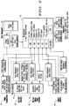
- Fig. 2 for a more detailed schematic of the workings of AED monitor 1.
- power management processes 101 communicate with microprocessor 12, the cellular communication 111, AED post detection 121, chirp detection 131, and the support hardware 141.
- the power management 101 typically will consists of a battery such as a lithium ion battery connected to a voltage regulator. As shown an aux RTC (real time clock) power source connects the power management to the microprocessor 12.
- aux RTC real time clock
- One skilled in the art may substitute or implement other suitable substitutes for powering the AED monitor 1.
- the cellular communication systems 111 are typically composed of power management circuitry and a cellular module.
- the communication devices can be SimCon (TM) or other similar link, however it should have HSDPA dual-band capabilities, while other protocols such as GSM/GPRS/EDGE capabilities may be preferred for certain applications.
- the cellular communications 111 report to a universal asynchronous receiver-transmitter (UART) or analogous part on the microprocessor 12.
- UART universal asynchronous receiver-transmitter
- the AED POST detection 121 systems generally relate to electromagnetic coil (or RF antenna) 15.
- the electromagnetic coil 15 is preferably a 100 kHz-1MHz PCB trace antenna for detecting electromagnetic fields emanating from the AED.
- a bandpass filter e.g. 3rd order Butterworth
- the signal may also need amplification (e.g. 2-stage Op-Amp) before reporting the signal to an analogue-to-digital converter (ADC) on the microprocessor 12.
- ADC analogue-to-digital converter
- the AED low-battery aka "chirp" detection 131 systems generally relate to Microphone 16.
- the microphone 16 is preferably a microphone electret or MEMS for detecting beeps, chirps, and other sounds emitted by the AED.
- the signal may also need amplification (e.g. Op-Amp) before reporting the signal to an analogue-to-digital converter (ADC) on the microprocessor 12.
- ADC analogue-to-digital converter
- Support hardware 141 may be implemented on microprocessor 12, or be connected to the chip. External memory and update storage may be connected with a serial peripheral interface (SPI). A crystal oscillator may perform RTC capabilities, or act as a secondary check for the processor 12. In addition a JTAG (joint test action group) or SWD (serial wire debug) Header may be implemented for debugging.
- SPI serial peripheral interface
- JTAG joint test action group
- SWD serial wire debug
- Diagnostics 151 may also be present on the AED monitor 1, for users to interface with the AED monitor. For example, LEDs may be used to show battery and network status of the AED monitor. To maintain low battery usage in the resting state, a button would cause the diagnostics 151 to trigger, thus activating the LED to show the AED monitor's 1 status.
- FIG. 3 an implementation of AED monitor 1 is shown.
- Automatic external defibrillator 2 and AED monitor 1 are placed inside a typical AED Cabinet 200.
- the door 201 is shut and the AED is visible through window 202.
- a hole is made in the cabinet 200 and antenna 16 is drawn through the cabinet so it is on the exterior. This reduces interference with signals to the AED monitor 1.
- the monitor 1 is typically placed in the back of the cabinet 200 where it will not interfere with operation of the AED in emergencies.
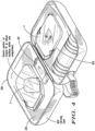
- FIG. 4 another implementation of AED monitor 1 is shown.
- Automatic external defibrillator 2 and AED monitor 1 are placed inside a mobile AED carrying case 300.
- AED carrying case 300 In a typical case there may be additional batteries 301 and a closable top 302. Some cases cause interference with signals to the AED, however, the AED monitor 1 according to the present invention has several advantages discussed herein to enable communication outside case 300.
- the monitor 1 is typically placed in case 300 where it will not interfere with operation of the AED in emergencies.
- FIG. 5 essentially illustrates a method 500 of operation for AED monitor 1.
- AED monitor 1 After installation into a cabinet 300, bag 400, or other AED installation, AED monitor 1 should begin the setup/startup processes. The startup process then begins to detect electromagnetic (RF) signals from the AED 502. This process can be improved by manually entering values into the monitor 1 prior to installation. However, the monitor can be installed without pre-programming, in such cases the AED monitor 1 then detects electromagnetic signals from the AED for a minimum of 2 self tests which then allows it to establish a time (T) that the AED conducts self tests, and a frequency (F) that it conducts tests. After T and F are established, the monitor then moves to start low-power monitoring 503 of the AED.
- T time
- F frequency
- the monitor 1 then remains in sleep mode 504 until the Time (T) for waking up to the active mode using the T & F variables stored previously.
- the monitor 1 inquires whether the AED's electromagnetic signal is detected 505, if not the AED is reported as missing or dead 506. If an electromagnetic signal is detected the monitor 1 listens for an audible beep 507, if the correct beep or beep sequence is detected the monitor reports the AED is in a fault state 508.
- the monitor 1 inquires whether it is time for a fixed 2-way communication with a remote monitor 509, typically this is done on a weekly basis, but may be adjusted to a bi-weekly or monthly basis to save battery, if it is not time the monitor 1 returns to low power monitoring 503, if it is time to report, then a report is issued 510, then the monitor 1 returns to low-power monitoring.
- the All AEDs turn on at a selected interval for a self inspection. Most turn on every 24 hours for a quick check, every week for a more thorough self inspection, and every month for a complete inspection. These inspections not only check the batteries and pads, but also the internal functions of the AED including the charge circuitry. Following these inspections a pass or fail visual indicator is set, as well as a periodic beep in a fault state.
- a basic method of operation contemplated by the AED monitor 1 of the present disclosure is as follows: 1) Wake up the monitoring system from sleep mode to the active state 1 just prior to scheduled AED self inspection; 2) Sense the wake up of the AED for its self inspection with electromagnetic monitor 15; 3) Listen with microphone 14 for a fault signal for a defined period of time, and if the fault signal is discovered a fault condition is present; 4) Report via wireless communication (Wi-Fi, Bluetooth, RF, etc) over antenna 16 the outcome of monitoring; 5) Return monitoring system to battery 13 conservation, sleep mode.
- AEDs go through a self test on a regular schedule. Most go through a 24 hour functional test that requires only minimal current draw from the battery. Most AEDs also go through a more extensive weekly test, often charging the capacitors to a percentage of their full capacity and discharging. Additionally, most AEDs go through a 4 week or monthly extensive self test where they fully charge and discharge the capacitors. It is this periodic turn on period that allows our interference sensing coil 16 to determine if the AED is present and if the AED battery has sufficient power to turn on. A useful aspect of the AED self check is that it turns on at a predetermined periodic interval.
- a common AED known to one skilled in the art turns on daily at 3:03am.
- the user can enter the AED type on setup, allowing the electronics to remain in sleep mode up to the point of test, and turn back off immediately after, preserving battery life 13.
- all AEDs will transmit a periodic beep if they detect a problem during their self test
- Microphone 14 listens for this periodic beep that will be used immediately following the positive output from the interference coil to determine the status of the AED, other than missing or a completely dead battery.
- AED monitor 1 Installation of AED monitor 1 is kept simple so AED technicians can easily install a monitor. Installation and setup can typically be done by the installer's phone through Bluetooth. Wi-Fi connection and setup parameters can be done using a phone application. Setup parameters may include AED model, Wi-Fi selection, fault communication method and phone/address, etc.
Landscapes
- Health & Medical Sciences (AREA)
- Cardiology (AREA)
- Heart & Thoracic Surgery (AREA)
- Engineering & Computer Science (AREA)
- Biomedical Technology (AREA)
- Nuclear Medicine, Radiotherapy & Molecular Imaging (AREA)
- Radiology & Medical Imaging (AREA)
- Life Sciences & Earth Sciences (AREA)
- Animal Behavior & Ethology (AREA)
- General Health & Medical Sciences (AREA)
- Public Health (AREA)
- Veterinary Medicine (AREA)
- Electrotherapy Devices (AREA)
Claims (8)
- Combinaison d'un défibrillateur externe automatisé, AED, et d'un système de surveillance d'AED comprenant :l'AED (2) qui comporte un sous-programme d'autodiagnostic et qui est adapté pour exécuter ledit sous-programme selon des intervalles réguliers, l'AED (2) comportant au moins un indicateur audio qui est adapté pour indiquer les résultats de l'autodiagnostic lorsque le diagnostic consiste en ce que l'AED a besoin d'une maintenance ;le système de surveillance d'AED, dans laquelle le système de surveillance d'AED (1) est à distance de l'AED (2), le système de surveillance d'AED comportant un microphone (14), une batterie (13), un microprocesseur (12), un dispositif de communication sans fil (16) et une bobine électromagnétique (15), la bobine (15) étant une bobine à multiples spires, la bobine (15) pouvant détecter un signal électromagnétique généré par l'AED lorsque l'AED est mis en fonctionnement,dans laquelle, lors d'une procédure de démarrage du système de surveillance d'AED, ledit système est adapté pour détecter un signal électromagnétique pour établir un temps et un intervalle lorsque l'AED (2) met en œuvre un test d'autodiagnostic ;dans laquelle le microprocesseur (12) est adapté pour mettre en fonctionnement le système de surveillance d'AED avant l'autodiagnostic d'AED conformément au temps et à l'intervalle établis ;dans laquelle le microprocesseur (12) est adapté pour surveiller la bobine (15) à l'instant de l'exécution du sous-programme d'autodiagnostic pour vérifier que l'AED est présent et que la batterie d'AED (13) n'est pas à plat ;dans laquelle le microprocesseur (12) est adapté pour utiliser le microphone (14) pour surveiller, en considération de l'indicateur audio d'AED, le fait que l'AED (2) a besoin d'une maintenance ;dans laquelle le microprocesseur (12) est adapté pour transmettre un signal sans fil par l'intermédiaire du dispositif de communication sans fil (16) à un système de surveillance en ligne pour indiquer si l'AED a besoin ou non d'une maintenance sur la base du signal électromagnétique en provenance de l'AED et du signal audible en provenance de l'AED ; etdans laquelle le microprocesseur (12) est adapté pour faire passer le système de surveillance d'AED d'un état d'activation dans un mode sommeil après la transmission du signal sans fil.
- Combinaison selon la revendication 1, comprenant en outre le système de surveillance en ligne, le système de surveillance en ligne étant adapté pour recevoir des transmissions en provenance du système de surveillance d'AED (1) et pour rapporter à un utilisateur si l'AED a besoin ou non d'une maintenance.
- Combinaison selon la revendication 1 ou 2, comprenant en outre un cabinet d'AED, le cabinet d'AED (200) renfermant l'AED et le système de surveillance d'AED (1) ;
le dispositif de communication sans fil étant monté sur le cabinet d'AED et étant connecté aux parties restantes du système de surveillance d'AED à distance (1) . - Combinaison selon l'une quelconque des revendications 1 et 2, comprenant en outre un contenant d'AED (400), le contenant d'AED contenant l'AED et le système de surveillance d'AED (1).
- Combinaison selon la revendication 1, dans laquelle le système de surveillance d'AED (1) comprend en outre :
un boîtier (11) et dans laquelle le dispositif de communication sans fil est une antenne (16). - Combinaison selon la revendication 5, dans laquelle le boîtier (11) présente :une largeur de 88,9 mm (trois pouces et demi (3.5")) ou moins ;une hauteur de 88,9 mm (trois pouces et demi (3.5")) ou moins ; etune profondeur de 12,7 mm (un demi-pouce (0.5")) ou moins.
- Procédé pour surveiller et rapporter l'état d'un défibrillateur externe automatisé, AED (2), via un système de surveillance d'AED (1), dans lequel le système de surveillance d'AED (1) est à distance de l'AED (2), dans lequel l'AED comprend un indicateur audio pour indiquer un résultat d'un test d'autodiagnostic lorsque le diagnostic consiste en ce que l'AED a besoin d'une maintenance, et dans lequel le système de surveillance d'AED (1) comprend :une batterie, un microprocesseur, un dispositif de communication sans fil et une bobine électromagnétique (15), la bobine (15) étant une bobine à multiples spires, la bobine (15) pouvant détecter un signal électromagnétique généré par l'AED lorsque l'AED est mis en fonctionnement ; et un microphone (14) permettant de détecter des signaux audibles en provenance de l'AED ;le procédé comprenant :la fourniture de l'AED (2) et du système de surveillance d'AED (1) ;la détection, par le système de surveillance d'AED, d'un signal électromagnétique en provenance de l'AED (2) pour établir un temps et un intervalle lorsque l'AED (2) met en œuvre le test d'autodiagnostic ;le placement (503) du système de surveillance d'AED (1) dans un mode sommeil ;le maintien (504) du système de surveillance d'AED (1) dans un mode sommeil ;la mise en fonctionnement, conformément au temps et à l'intervalle établis lorsque l'AED (2) met en œuvre un test d'autodiagnostic, du système de surveillance d'AED (1) dans un état actif à un temps sélectionné avant que l'AED ne mette en œuvre le test d'autodiagnostic ;la détection (505), en utilisant la bobine (15), de si un signal électromagnétique est émis ou non depuis l'AED ;la détection (507), en utilisant le microphone (14), de si un signal audible est émis ou non depuis l'AED, dans lequel le signal audible indique le résultat du test d'autodiagnostic ;la transmission sans fil (506, 508, 510), à un système de surveillance en ligne, d'une indication de si l'AED a besoin ou non d'une maintenance sur la base du signal électromagnétique en provenance de l'AED et du signal audible en provenance de l'AED ; etaprès la transmission, le retour du système de surveillance d'AED (1) dans le mode sommeil.
- Procédé selon la revendication 7, dans lequel l'AED est configuré pour effectuer le test d'autodiagnostic selon des intervalles de 24 heures.
Priority Applications (1)
| Application Number | Priority Date | Filing Date | Title |
|---|---|---|---|
| EP24199284.1A EP4494694A1 (fr) | 2017-10-18 | 2018-10-11 | Système de surveillance à distance d'un défibrillateur externe automatisé |
Applications Claiming Priority (1)
| Application Number | Priority Date | Filing Date | Title |
|---|---|---|---|
| US15/787,412 US11185708B2 (en) | 2017-10-18 | 2017-10-18 | Heartstation remote monitor system |
Related Child Applications (2)
| Application Number | Title | Priority Date | Filing Date |
|---|---|---|---|
| EP24199284.1A Division-Into EP4494694A1 (fr) | 2017-10-18 | 2018-10-11 | Système de surveillance à distance d'un défibrillateur externe automatisé |
| EP24199284.1A Division EP4494694A1 (fr) | 2017-10-18 | 2018-10-11 | Système de surveillance à distance d'un défibrillateur externe automatisé |
Publications (3)
| Publication Number | Publication Date |
|---|---|
| EP3473297A1 EP3473297A1 (fr) | 2019-04-24 |
| EP3473297B1 true EP3473297B1 (fr) | 2024-11-20 |
| EP3473297C0 EP3473297C0 (fr) | 2024-11-20 |
Family
ID=63833884
Family Applications (2)
| Application Number | Title | Priority Date | Filing Date |
|---|---|---|---|
| EP24199284.1A Pending EP4494694A1 (fr) | 2017-10-18 | 2018-10-11 | Système de surveillance à distance d'un défibrillateur externe automatisé |
| EP18199800.6A Active EP3473297B1 (fr) | 2017-10-18 | 2018-10-11 | Système de surveillance à distance d'un défibrillateur externe automatisé |
Family Applications Before (1)
| Application Number | Title | Priority Date | Filing Date |
|---|---|---|---|
| EP24199284.1A Pending EP4494694A1 (fr) | 2017-10-18 | 2018-10-11 | Système de surveillance à distance d'un défibrillateur externe automatisé |
Country Status (4)
| Country | Link |
|---|---|
| US (2) | US11185708B2 (fr) |
| EP (2) | EP4494694A1 (fr) |
| CA (1) | CA3020014C (fr) |
| ES (1) | ES3001156T3 (fr) |
Families Citing this family (9)
| Publication number | Priority date | Publication date | Assignee | Title |
|---|---|---|---|---|
| US11524168B2 (en) | 2016-12-19 | 2022-12-13 | Hearthero, Inc. | Self-contained, connected automated external defibrillator systems and methods of use |
| US11185708B2 (en) * | 2017-10-18 | 2021-11-30 | Rescuestat Llc | Heartstation remote monitor system |
| US10909830B1 (en) * | 2017-11-07 | 2021-02-02 | Pica Product Development, Llc | Personal emergency alert system, method and device |
| US10694338B2 (en) * | 2017-11-07 | 2020-06-23 | Pica Product Development, Llc | Cellular automated external defibrillator (AED) tracker |
| US10798541B2 (en) | 2017-11-07 | 2020-10-06 | Pica Product Development, Llc | Systems, methods and devices for remote trap monitoring |
| US12594431B2 (en) * | 2023-05-02 | 2026-04-07 | Avive Solutions, Inc. | AED actions remotely triggered by AED management platform |
| WO2022072734A1 (fr) | 2020-09-30 | 2022-04-07 | Zoll Medical Corporation | Dispositifs de surveillance à distance et procédés et systèmes associés à écoute de signaux de dea audibles |
| EP4228742B1 (fr) | 2020-10-14 | 2026-03-25 | HeartHero, Inc. | Systèmes de défibrillateur externe automatisé et procédés d'utilisation |
| US11529526B1 (en) * | 2021-12-10 | 2022-12-20 | Hearthero, Inc. | Automated external defibrillator |
Family Cites Families (30)
| Publication number | Priority date | Publication date | Assignee | Title |
|---|---|---|---|---|
| US5879374A (en) | 1993-05-18 | 1999-03-09 | Heartstream, Inc. | External defibrillator with automatic self-testing prior to use |
| US7728715B2 (en) | 1996-01-23 | 2010-06-01 | En-Gauge, Inc. | Remote monitoring |
| US6366809B1 (en) * | 1997-04-08 | 2002-04-02 | Survivalink Corporation | Defibrillator battery with memory and status indication guage |
| US7930023B2 (en) | 2001-09-21 | 2011-04-19 | Defibtech, Llc | Automatic external defibrillator with active status indicator |
| US7120488B2 (en) | 2002-05-07 | 2006-10-10 | Medtronic Physio-Control Manufacturing Corp. | Therapy-delivering portable medical device capable of triggering and communicating with an alarm system |
| US7570994B2 (en) | 2003-04-25 | 2009-08-04 | Medtronic Physio-Control Corp. | Apparatus and method for maintaining a defibrillator battery charge and optionally communicating |
| EP1827572B1 (fr) * | 2004-10-29 | 2017-12-13 | Koninklijke Philips N.V. | Electrode et boitier pour surveillance et traitement cardiaques |
| US9008767B2 (en) | 2004-11-18 | 2015-04-14 | Scion Medical Limited | System and method for performing self-test in an automatic external defribillator (AED) |
| US7510526B2 (en) | 2004-12-30 | 2009-03-31 | Medtronic Emergency Response Systems, Inc. | Medical device information system |
| US8116863B2 (en) | 2006-03-21 | 2012-02-14 | Defibtech, Llc | System and method for effectively indicating element failure or a preventive maintenance condition in an automatic external defibrillator (AED) |
| AU2007203529B2 (en) | 2006-12-01 | 2012-08-30 | Cardiac Responder, Inc. | Automated external defibrillator system |
| US8369944B2 (en) | 2007-06-06 | 2013-02-05 | Zoll Medical Corporation | Wearable defibrillator with audio input/output |
| FR2946539A1 (fr) | 2009-06-16 | 2010-12-17 | Cardio Assistance | Detection d'un defaut de maintenance d'un defibrillateur cardiaque externe par analyse de son et transmission a travers un reseau public de communication |
| US8565871B2 (en) | 2009-09-07 | 2013-10-22 | Qualcomm Incorporated | Automated external defibrillator device with integrated wireless modem |
| DE102011001678A1 (de) | 2011-03-30 | 2012-10-04 | Medic Assist Gmbh & Co. Kg | Überwachungssystem |
| US8684134B2 (en) | 2012-06-27 | 2014-04-01 | Usg Interiors, Llc | Gypsum-panel acoustical monolithic ceiling |
| US9220912B2 (en) | 2012-07-26 | 2015-12-29 | Zoll Medical Corporation | Medical equipment servicing |
| US9295849B2 (en) | 2012-07-27 | 2016-03-29 | Zoll Medical Corporation | Medical equipment messaging |
| CN104548350B (zh) | 2013-10-16 | 2017-11-03 | 蔡育秀 | 自动体外除颤器状态侦测回报装置及其方法 |
| TWM478517U (zh) | 2013-10-16 | 2014-05-21 | Yuh-Show Tsai | 自動體外去顫器狀態偵測回報裝置 |
| KR101780214B1 (ko) | 2013-11-29 | 2017-10-10 | (주)나눔테크 | 자동제세동기를 이용한 응급 구조시스템 |
| PL3271007T3 (pl) * | 2015-03-19 | 2023-11-13 | Zoll Medical Corporation | Układ rozprowadzania żelu przewodzącego |
| EP3277374B1 (fr) | 2015-03-30 | 2025-01-01 | ZOLL Medical Corporation | Gestion de dispositifs médicaux |
| US10578677B2 (en) * | 2015-06-30 | 2020-03-03 | Zoll Medical Corporation | Systems and methods for monitoring battery life status |
| JP6526341B2 (ja) | 2016-01-11 | 2019-06-05 | コーニンクレッカ フィリップス エヌ ヴェKoninklijke Philips N.V. | 除細動器状態インジケータの非可聴感知に対する方法及び装置 |
| US11207535B2 (en) | 2016-03-21 | 2021-12-28 | Koninklijke Philips N.V. | Fault identification logic in an external readiness monitor for an automated external defibrillator (AED) |
| EP3525878B1 (fr) | 2016-10-12 | 2020-11-11 | Koninklijke Philips N.V. | Surpassement d'alerte de test de diagnostic d'échec dans un défibrillateur automatisé externe (dae) |
| US10668296B2 (en) * | 2016-11-23 | 2020-06-02 | Cardifab Ltd. | Device and method for generating electrical stimulation |
| US10737105B2 (en) | 2017-10-02 | 2020-08-11 | Avive Solutions, Inc. | Modular defibrillator architecture |
| US11185708B2 (en) * | 2017-10-18 | 2021-11-30 | Rescuestat Llc | Heartstation remote monitor system |
-
2017
- 2017-10-18 US US15/787,412 patent/US11185708B2/en active Active
-
2018
- 2018-10-05 CA CA3020014A patent/CA3020014C/fr active Active
- 2018-10-11 ES ES18199800T patent/ES3001156T3/es active Active
- 2018-10-11 EP EP24199284.1A patent/EP4494694A1/fr active Pending
- 2018-10-11 EP EP18199800.6A patent/EP3473297B1/fr active Active
-
2021
- 2021-09-02 US US17/465,671 patent/US11801392B2/en active Active
Also Published As
| Publication number | Publication date |
|---|---|
| ES3001156T3 (es) | 2025-03-04 |
| US11801392B2 (en) | 2023-10-31 |
| EP3473297A1 (fr) | 2019-04-24 |
| CA3020014C (fr) | 2026-04-07 |
| EP3473297C0 (fr) | 2024-11-20 |
| EP4494694A1 (fr) | 2025-01-22 |
| CA3020014A1 (fr) | 2019-04-18 |
| US11185708B2 (en) | 2021-11-30 |
| US20190111272A1 (en) | 2019-04-18 |
| US20210393969A1 (en) | 2021-12-23 |
Similar Documents
| Publication | Publication Date | Title |
|---|---|---|
| US11801392B2 (en) | Heartstation remote monitor system | |
| US8319632B1 (en) | System and method for monitoring external portable medical devices | |
| US8416084B2 (en) | Wireless patient monitoring system | |
| US9035787B2 (en) | Centralized management and emergency allocation of deployed defibrillators each having associated communication modules | |
| CA2971575C (fr) | Systeme et procede de surveillance d'une personne | |
| US20040049233A1 (en) | Medical device status information system | |
| US20090015403A1 (en) | Method and mechanism for assisted diagnosis and maintenance of health monitoring system | |
| WO2013192167A1 (fr) | Essai et fonctionnement de dispositif de sécurité intelligent | |
| EP3525878B1 (fr) | Surpassement d'alerte de test de diagnostic d'échec dans un défibrillateur automatisé externe (dae) | |
| US9827456B2 (en) | Firefighting equipment inspection notification device | |
| JP2013097761A (ja) | 医療機器運用管理システム | |
| CA3082221A1 (fr) | Dispositif d`avertissement personnel de distanciation physique | |
| CN111145375A (zh) | 灭火器监控系统及方法 | |
| EP3698846B1 (fr) | Défibrillateur, procédé de gestion de détection d'état, système et dispositif de gestion de détection d'état | |
| CN110361989A (zh) | 自动体外除颤器管理系统 | |
| JP2017120491A (ja) | 警備業務支援システムおよび警備装置 | |
| JP2021089500A (ja) | サーバ装置及びプログラム | |
| CN108653948A (zh) | 智能防坠落安全带及安全系统 | |
| JP5594042B2 (ja) | 緊急通報システム、無線端末及び制御装置 | |
| CN208013703U (zh) | 自动体外除颤器管理系统 | |
| KR20190095570A (ko) | IoT 기반 AED 관리 시스템 및 방법 | |
| CN210427660U (zh) | 设备运行监测器 | |
| KR101631010B1 (ko) | 자동제세동기의 저전력 운영 시스템 | |
| CN205881110U (zh) | 一种人员的位置区域管理系统 | |
| CA2588891A1 (fr) | Dispositif de rappel d'essai de detecteur de fumee |
Legal Events
| Date | Code | Title | Description |
|---|---|---|---|
| PUAI | Public reference made under article 153(3) epc to a published international application that has entered the european phase |
Free format text: ORIGINAL CODE: 0009012 |
|
| STAA | Information on the status of an ep patent application or granted ep patent |
Free format text: STATUS: THE APPLICATION HAS BEEN PUBLISHED |
|
| AK | Designated contracting states |
Kind code of ref document: A1 Designated state(s): AL AT BE BG CH CY CZ DE DK EE ES FI FR GB GR HR HU IE IS IT LI LT LU LV MC MK MT NL NO PL PT RO RS SE SI SK SM TR |
|
| AX | Request for extension of the european patent |
Extension state: BA ME |
|
| STAA | Information on the status of an ep patent application or granted ep patent |
Free format text: STATUS: REQUEST FOR EXAMINATION WAS MADE |
|
| 17P | Request for examination filed |
Effective date: 20191022 |
|
| RBV | Designated contracting states (corrected) |
Designated state(s): AL AT BE BG CH CY CZ DE DK EE ES FI FR GB GR HR HU IE IS IT LI LT LU LV MC MK MT NL NO PL PT RO RS SE SI SK SM TR |
|
| STAA | Information on the status of an ep patent application or granted ep patent |
Free format text: STATUS: EXAMINATION IS IN PROGRESS |
|
| 17Q | First examination report despatched |
Effective date: 20210111 |
|
| RAP1 | Party data changed (applicant data changed or rights of an application transferred) |
Owner name: RESCUESTAT LLC |
|
| RIN1 | Information on inventor provided before grant (corrected) |
Inventor name: HOCHHALTER, KEITH |
|
| GRAP | Despatch of communication of intention to grant a patent |
Free format text: ORIGINAL CODE: EPIDOSNIGR1 |
|
| STAA | Information on the status of an ep patent application or granted ep patent |
Free format text: STATUS: GRANT OF PATENT IS INTENDED |
|
| INTG | Intention to grant announced |
Effective date: 20240103 |
|
| GRAJ | Information related to disapproval of communication of intention to grant by the applicant or resumption of examination proceedings by the epo deleted |
Free format text: ORIGINAL CODE: EPIDOSDIGR1 |
|
| STAA | Information on the status of an ep patent application or granted ep patent |
Free format text: STATUS: EXAMINATION IS IN PROGRESS |
|
| INTC | Intention to grant announced (deleted) | ||
| GRAP | Despatch of communication of intention to grant a patent |
Free format text: ORIGINAL CODE: EPIDOSNIGR1 |
|
| STAA | Information on the status of an ep patent application or granted ep patent |
Free format text: STATUS: GRANT OF PATENT IS INTENDED |
|
| INTG | Intention to grant announced |
Effective date: 20240516 |
|
| GRAS | Grant fee paid |
Free format text: ORIGINAL CODE: EPIDOSNIGR3 |
|
| GRAA | (expected) grant |
Free format text: ORIGINAL CODE: 0009210 |
|
| STAA | Information on the status of an ep patent application or granted ep patent |
Free format text: STATUS: THE PATENT HAS BEEN GRANTED |
|
| AK | Designated contracting states |
Kind code of ref document: B1 Designated state(s): AL AT BE BG CH CY CZ DE DK EE ES FI FR GB GR HR HU IE IS IT LI LT LU LV MC MK MT NL NO PL PT RO RS SE SI SK SM TR |
|
| REG | Reference to a national code |
Ref country code: GB Ref legal event code: FG4D |
|
| REG | Reference to a national code |
Ref country code: CH Ref legal event code: EP |
|
| REG | Reference to a national code |
Ref country code: DE Ref legal event code: R096 Ref document number: 602018076678 Country of ref document: DE |
|
| REG | Reference to a national code |
Ref country code: IE Ref legal event code: FG4D |
|
| U01 | Request for unitary effect filed |
Effective date: 20241120 |
|
| U07 | Unitary effect registered |
Designated state(s): AT BE BG DE DK EE FI FR IT LT LU LV MT NL PT RO SE SI Effective date: 20241126 |
|
| REG | Reference to a national code |
Ref country code: ES Ref legal event code: FG2A Ref document number: 3001156 Country of ref document: ES Kind code of ref document: T3 Effective date: 20250304 |
|
| PG25 | Lapsed in a contracting state [announced via postgrant information from national office to epo] |
Ref country code: IS Free format text: LAPSE BECAUSE OF FAILURE TO SUBMIT A TRANSLATION OF THE DESCRIPTION OR TO PAY THE FEE WITHIN THE PRESCRIBED TIME-LIMIT Effective date: 20250320 Ref country code: HR Free format text: LAPSE BECAUSE OF FAILURE TO SUBMIT A TRANSLATION OF THE DESCRIPTION OR TO PAY THE FEE WITHIN THE PRESCRIBED TIME-LIMIT Effective date: 20241120 |
|
| PG25 | Lapsed in a contracting state [announced via postgrant information from national office to epo] |
Ref country code: NO Free format text: LAPSE BECAUSE OF FAILURE TO SUBMIT A TRANSLATION OF THE DESCRIPTION OR TO PAY THE FEE WITHIN THE PRESCRIBED TIME-LIMIT Effective date: 20250220 |
|
| PG25 | Lapsed in a contracting state [announced via postgrant information from national office to epo] |
Ref country code: GR Free format text: LAPSE BECAUSE OF FAILURE TO SUBMIT A TRANSLATION OF THE DESCRIPTION OR TO PAY THE FEE WITHIN THE PRESCRIBED TIME-LIMIT Effective date: 20250221 |
|
| PG25 | Lapsed in a contracting state [announced via postgrant information from national office to epo] |
Ref country code: PL Free format text: LAPSE BECAUSE OF FAILURE TO SUBMIT A TRANSLATION OF THE DESCRIPTION OR TO PAY THE FEE WITHIN THE PRESCRIBED TIME-LIMIT Effective date: 20241120 |
|
| PG25 | Lapsed in a contracting state [announced via postgrant information from national office to epo] |
Ref country code: RS Free format text: LAPSE BECAUSE OF FAILURE TO SUBMIT A TRANSLATION OF THE DESCRIPTION OR TO PAY THE FEE WITHIN THE PRESCRIBED TIME-LIMIT Effective date: 20250220 |
|
| PG25 | Lapsed in a contracting state [announced via postgrant information from national office to epo] |
Ref country code: SM Free format text: LAPSE BECAUSE OF FAILURE TO SUBMIT A TRANSLATION OF THE DESCRIPTION OR TO PAY THE FEE WITHIN THE PRESCRIBED TIME-LIMIT Effective date: 20241120 |
|
| PG25 | Lapsed in a contracting state [announced via postgrant information from national office to epo] |
Ref country code: SK Free format text: LAPSE BECAUSE OF FAILURE TO SUBMIT A TRANSLATION OF THE DESCRIPTION OR TO PAY THE FEE WITHIN THE PRESCRIBED TIME-LIMIT Effective date: 20241120 |
|
| PG25 | Lapsed in a contracting state [announced via postgrant information from national office to epo] |
Ref country code: CZ Free format text: LAPSE BECAUSE OF FAILURE TO SUBMIT A TRANSLATION OF THE DESCRIPTION OR TO PAY THE FEE WITHIN THE PRESCRIBED TIME-LIMIT Effective date: 20241120 |
|
| PLBE | No opposition filed within time limit |
Free format text: ORIGINAL CODE: 0009261 |
|
| STAA | Information on the status of an ep patent application or granted ep patent |
Free format text: STATUS: NO OPPOSITION FILED WITHIN TIME LIMIT |
|
| 26N | No opposition filed |
Effective date: 20250821 |
|
| REG | Reference to a national code |
Ref country code: CH Ref legal event code: U11 Free format text: ST27 STATUS EVENT CODE: U-0-0-U10-U11 (AS PROVIDED BY THE NATIONAL OFFICE) Effective date: 20251101 |
|
| U20 | Renewal fee for the european patent with unitary effect paid |
Year of fee payment: 8 Effective date: 20251016 |
|
| PGFP | Annual fee paid to national office [announced via postgrant information from national office to epo] |
Ref country code: GB Payment date: 20251016 Year of fee payment: 8 |
|
| PGFP | Annual fee paid to national office [announced via postgrant information from national office to epo] |
Ref country code: CH Payment date: 20251101 Year of fee payment: 8 |
|
| PGFP | Annual fee paid to national office [announced via postgrant information from national office to epo] |
Ref country code: IE Payment date: 20251020 Year of fee payment: 8 |
|
| PGFP | Annual fee paid to national office [announced via postgrant information from national office to epo] |
Ref country code: ES Payment date: 20251118 Year of fee payment: 8 |