EP3473303B1 - Microprocessor-controlled system for human physical training - Google Patents
Microprocessor-controlled system for human physical training Download PDFInfo
- Publication number
- EP3473303B1 EP3473303B1 EP17814344.2A EP17814344A EP3473303B1 EP 3473303 B1 EP3473303 B1 EP 3473303B1 EP 17814344 A EP17814344 A EP 17814344A EP 3473303 B1 EP3473303 B1 EP 3473303B1
- Authority
- EP
- European Patent Office
- Prior art keywords
- speed
- pulley
- brake
- selector
- microprocessor
- Prior art date
- Legal status (The legal status is an assumption and is not a legal conclusion. Google has not performed a legal analysis and makes no representation as to the accuracy of the status listed.)
- Active
Links
Images


Classifications
-
- A—HUMAN NECESSITIES
- A63—SPORTS; GAMES; AMUSEMENTS
- A63B—APPARATUS FOR PHYSICAL TRAINING, GYMNASTICS, SWIMMING, CLIMBING, OR FENCING; BALL GAMES; TRAINING EQUIPMENT
- A63B21/00—Exercising apparatus for developing or strengthening the muscles or joints of the body by working against a counterforce, with or without measuring devices
- A63B21/15—Arrangements for force transmissions
- A63B21/151—Using flexible elements for reciprocating movements, e.g. ropes or chains
- A63B21/152—Bowden-type cables
-
- A—HUMAN NECESSITIES
- A63—SPORTS; GAMES; AMUSEMENTS
- A63B—APPARATUS FOR PHYSICAL TRAINING, GYMNASTICS, SWIMMING, CLIMBING, OR FENCING; BALL GAMES; TRAINING EQUIPMENT
- A63B24/00—Electric or electronic controls for exercising apparatus of preceding groups; Controlling or monitoring of exercises, sportive games, training or athletic performances
- A63B24/0087—Electric or electronic controls for exercising apparatus of groups A63B21/00 - A63B23/00, e.g. controlling load
-
- A—HUMAN NECESSITIES
- A61—MEDICAL OR VETERINARY SCIENCE; HYGIENE
- A61B—DIAGNOSIS; SURGERY; IDENTIFICATION
- A61B5/00—Measuring for diagnostic purposes; Identification of persons
- A61B5/22—Ergometry; Measuring muscular strength or the force of a muscular blow
-
- A—HUMAN NECESSITIES
- A63—SPORTS; GAMES; AMUSEMENTS
- A63B—APPARATUS FOR PHYSICAL TRAINING, GYMNASTICS, SWIMMING, CLIMBING, OR FENCING; BALL GAMES; TRAINING EQUIPMENT
- A63B21/00—Exercising apparatus for developing or strengthening the muscles or joints of the body by working against a counterforce, with or without measuring devices
- A63B21/00058—Mechanical means for varying the resistance
- A63B21/00076—Mechanical means for varying the resistance on the fly, i.e. varying the resistance during exercise
-
- A—HUMAN NECESSITIES
- A63—SPORTS; GAMES; AMUSEMENTS
- A63B—APPARATUS FOR PHYSICAL TRAINING, GYMNASTICS, SWIMMING, CLIMBING, OR FENCING; BALL GAMES; TRAINING EQUIPMENT
- A63B21/00—Exercising apparatus for developing or strengthening the muscles or joints of the body by working against a counterforce, with or without measuring devices
- A63B21/002—Exercising apparatus for developing or strengthening the muscles or joints of the body by working against a counterforce, with or without measuring devices isometric or isokinetic, i.e. substantial force variation without substantial muscle motion or wherein the speed of the motion is independent of the force applied by the user
-
- A—HUMAN NECESSITIES
- A63—SPORTS; GAMES; AMUSEMENTS
- A63B—APPARATUS FOR PHYSICAL TRAINING, GYMNASTICS, SWIMMING, CLIMBING, OR FENCING; BALL GAMES; TRAINING EQUIPMENT
- A63B21/00—Exercising apparatus for developing or strengthening the muscles or joints of the body by working against a counterforce, with or without measuring devices
- A63B21/005—Exercising apparatus for developing or strengthening the muscles or joints of the body by working against a counterforce, with or without measuring devices using electromagnetic or electric force-resisters
- A63B21/0058—Exercising apparatus for developing or strengthening the muscles or joints of the body by working against a counterforce, with or without measuring devices using electromagnetic or electric force-resisters using motors
-
- A—HUMAN NECESSITIES
- A63—SPORTS; GAMES; AMUSEMENTS
- A63B—APPARATUS FOR PHYSICAL TRAINING, GYMNASTICS, SWIMMING, CLIMBING, OR FENCING; BALL GAMES; TRAINING EQUIPMENT
- A63B21/00—Exercising apparatus for developing or strengthening the muscles or joints of the body by working against a counterforce, with or without measuring devices
- A63B21/008—Exercising apparatus for developing or strengthening the muscles or joints of the body by working against a counterforce, with or without measuring devices using hydraulic or pneumatic force-resisters
-
- A—HUMAN NECESSITIES
- A63—SPORTS; GAMES; AMUSEMENTS
- A63B—APPARATUS FOR PHYSICAL TRAINING, GYMNASTICS, SWIMMING, CLIMBING, OR FENCING; BALL GAMES; TRAINING EQUIPMENT
- A63B21/00—Exercising apparatus for developing or strengthening the muscles or joints of the body by working against a counterforce, with or without measuring devices
- A63B21/012—Exercising apparatus for developing or strengthening the muscles or joints of the body by working against a counterforce, with or without measuring devices using frictional force-resisters
- A63B21/015—Exercising apparatus for developing or strengthening the muscles or joints of the body by working against a counterforce, with or without measuring devices using frictional force-resisters including rotating or oscillating elements rubbing against fixed elements
-
- A—HUMAN NECESSITIES
- A63—SPORTS; GAMES; AMUSEMENTS
- A63B—APPARATUS FOR PHYSICAL TRAINING, GYMNASTICS, SWIMMING, CLIMBING, OR FENCING; BALL GAMES; TRAINING EQUIPMENT
- A63B21/00—Exercising apparatus for developing or strengthening the muscles or joints of the body by working against a counterforce, with or without measuring devices
- A63B21/02—Exercising apparatus for developing or strengthening the muscles or joints of the body by working against a counterforce, with or without measuring devices using resilient force-resisters
- A63B21/022—Exercising apparatus for developing or strengthening the muscles or joints of the body by working against a counterforce, with or without measuring devices using resilient force-resisters with springs acting at different parts of the stroke
-
- A—HUMAN NECESSITIES
- A63—SPORTS; GAMES; AMUSEMENTS
- A63B—APPARATUS FOR PHYSICAL TRAINING, GYMNASTICS, SWIMMING, CLIMBING, OR FENCING; BALL GAMES; TRAINING EQUIPMENT
- A63B21/00—Exercising apparatus for developing or strengthening the muscles or joints of the body by working against a counterforce, with or without measuring devices
- A63B21/02—Exercising apparatus for developing or strengthening the muscles or joints of the body by working against a counterforce, with or without measuring devices using resilient force-resisters
- A63B21/023—Wound springs
- A63B21/025—Spiral springs with turns lying substantially in plane surfaces
-
- A—HUMAN NECESSITIES
- A63—SPORTS; GAMES; AMUSEMENTS
- A63B—APPARATUS FOR PHYSICAL TRAINING, GYMNASTICS, SWIMMING, CLIMBING, OR FENCING; BALL GAMES; TRAINING EQUIPMENT
- A63B21/00—Exercising apparatus for developing or strengthening the muscles or joints of the body by working against a counterforce, with or without measuring devices
- A63B21/15—Arrangements for force transmissions
- A63B21/151—Using flexible elements for reciprocating movements, e.g. ropes or chains
- A63B21/153—Using flexible elements for reciprocating movements, e.g. ropes or chains wound-up and unwound during exercise, e.g. from a reel
-
- A—HUMAN NECESSITIES
- A63—SPORTS; GAMES; AMUSEMENTS
- A63B—APPARATUS FOR PHYSICAL TRAINING, GYMNASTICS, SWIMMING, CLIMBING, OR FENCING; BALL GAMES; TRAINING EQUIPMENT
- A63B21/00—Exercising apparatus for developing or strengthening the muscles or joints of the body by working against a counterforce, with or without measuring devices
- A63B21/15—Arrangements for force transmissions
- A63B21/151—Using flexible elements for reciprocating movements, e.g. ropes or chains
- A63B21/154—Using flexible elements for reciprocating movements, e.g. ropes or chains using special pulley-assemblies
-
- A—HUMAN NECESSITIES
- A63—SPORTS; GAMES; AMUSEMENTS
- A63B—APPARATUS FOR PHYSICAL TRAINING, GYMNASTICS, SWIMMING, CLIMBING, OR FENCING; BALL GAMES; TRAINING EQUIPMENT
- A63B21/00—Exercising apparatus for developing or strengthening the muscles or joints of the body by working against a counterforce, with or without measuring devices
- A63B21/40—Interfaces with the user related to strength training; Details thereof
- A63B21/4027—Specific exercise interfaces
- A63B21/4033—Handles, pedals, bars or platforms
- A63B21/4035—Handles, pedals, bars or platforms for operation by hand
-
- A—HUMAN NECESSITIES
- A63—SPORTS; GAMES; AMUSEMENTS
- A63B—APPARATUS FOR PHYSICAL TRAINING, GYMNASTICS, SWIMMING, CLIMBING, OR FENCING; BALL GAMES; TRAINING EQUIPMENT
- A63B21/00—Exercising apparatus for developing or strengthening the muscles or joints of the body by working against a counterforce, with or without measuring devices
- A63B21/40—Interfaces with the user related to strength training; Details thereof
- A63B21/4041—Interfaces with the user related to strength training; Details thereof characterised by the movements of the interface
- A63B21/4043—Free movement, i.e. the only restriction coming from the resistance
-
- A—HUMAN NECESSITIES
- A63—SPORTS; GAMES; AMUSEMENTS
- A63B—APPARATUS FOR PHYSICAL TRAINING, GYMNASTICS, SWIMMING, CLIMBING, OR FENCING; BALL GAMES; TRAINING EQUIPMENT
- A63B24/00—Electric or electronic controls for exercising apparatus of preceding groups; Controlling or monitoring of exercises, sportive games, training or athletic performances
-
- A—HUMAN NECESSITIES
- A63—SPORTS; GAMES; AMUSEMENTS
- A63B—APPARATUS FOR PHYSICAL TRAINING, GYMNASTICS, SWIMMING, CLIMBING, OR FENCING; BALL GAMES; TRAINING EQUIPMENT
- A63B71/00—Games or sports accessories not covered in groups A63B1/00 - A63B69/00
- A63B71/06—Indicating or scoring devices for games or players, or for other sports activities
- A63B71/0619—Displays, user interfaces and indicating devices, specially adapted for sport equipment, e.g. display mounted on treadmills
-
- B—PERFORMING OPERATIONS; TRANSPORTING
- B66—HOISTING; LIFTING; HAULING
- B66D—CAPSTANS; WINCHES; TACKLES, e.g. PULLEY BLOCKS; HOISTS
- B66D1/00—Rope, cable, or chain winding mechanisms; Capstans
- B66D1/28—Other constructional details
- B66D1/40—Control devices
- B66D1/48—Control devices automatic
- B66D1/485—Control devices automatic electrical
-
- G—PHYSICS
- G01—MEASURING; TESTING
- G01L—MEASURING FORCE, STRESS, TORQUE, WORK, MECHANICAL POWER, MECHANICAL EFFICIENCY, OR FLUID PRESSURE
- G01L1/00—Measuring force or stress, in general
-
- G—PHYSICS
- G05—CONTROLLING; REGULATING
- G05B—CONTROL OR REGULATING SYSTEMS IN GENERAL; FUNCTIONAL ELEMENTS OF SUCH SYSTEMS; MONITORING OR TESTING ARRANGEMENTS FOR SUCH SYSTEMS OR ELEMENTS
- G05B19/00—Program-control systems
- G05B19/02—Program-control systems electric
- G05B19/04—Program control other than numerical control, i.e. in sequence controllers or logic controllers
- G05B19/048—Monitoring; Safety
-
- G—PHYSICS
- G06—COMPUTING OR CALCULATING; COUNTING
- G06F—ELECTRIC DIGITAL DATA PROCESSING
- G06F3/00—Input arrangements for transferring data to be processed into a form capable of being handled by the computer; Output arrangements for transferring data from processing unit to output unit, e.g. interface arrangements
- G06F3/01—Input arrangements or combined input and output arrangements for interaction between user and computer
- G06F3/03—Arrangements for converting the position or the displacement of a member into a coded form
- G06F3/041—Digitisers, e.g. for touch screens or touch pads, characterised by the transducing means
- G06F3/0416—Control or interface arrangements specially adapted for digitisers
-
- A—HUMAN NECESSITIES
- A63—SPORTS; GAMES; AMUSEMENTS
- A63B—APPARATUS FOR PHYSICAL TRAINING, GYMNASTICS, SWIMMING, CLIMBING, OR FENCING; BALL GAMES; TRAINING EQUIPMENT
- A63B71/00—Games or sports accessories not covered in groups A63B1/00 - A63B69/00
- A63B71/06—Indicating or scoring devices for games or players, or for other sports activities
- A63B2071/0675—Input for modifying training controls during workout
- A63B2071/0683—Input by handheld remote control
-
- A—HUMAN NECESSITIES
- A63—SPORTS; GAMES; AMUSEMENTS
- A63B—APPARATUS FOR PHYSICAL TRAINING, GYMNASTICS, SWIMMING, CLIMBING, OR FENCING; BALL GAMES; TRAINING EQUIPMENT
- A63B2220/00—Measuring of physical parameters relating to sporting activity
- A63B2220/30—Speed
-
- A—HUMAN NECESSITIES
- A63—SPORTS; GAMES; AMUSEMENTS
- A63B—APPARATUS FOR PHYSICAL TRAINING, GYMNASTICS, SWIMMING, CLIMBING, OR FENCING; BALL GAMES; TRAINING EQUIPMENT
- A63B2220/00—Measuring of physical parameters relating to sporting activity
- A63B2220/30—Speed
- A63B2220/34—Angular speed
-
- A—HUMAN NECESSITIES
- A63—SPORTS; GAMES; AMUSEMENTS
- A63B—APPARATUS FOR PHYSICAL TRAINING, GYMNASTICS, SWIMMING, CLIMBING, OR FENCING; BALL GAMES; TRAINING EQUIPMENT
- A63B2220/00—Measuring of physical parameters relating to sporting activity
- A63B2220/50—Force related parameters
- A63B2220/51—Force
-
- A—HUMAN NECESSITIES
- A63—SPORTS; GAMES; AMUSEMENTS
- A63B—APPARATUS FOR PHYSICAL TRAINING, GYMNASTICS, SWIMMING, CLIMBING, OR FENCING; BALL GAMES; TRAINING EQUIPMENT
- A63B2220/00—Measuring of physical parameters relating to sporting activity
- A63B2220/80—Special sensors, transducers or devices therefor
- A63B2220/83—Special sensors, transducers or devices therefor characterised by the position of the sensor
- A63B2220/833—Sensors arranged on the exercise apparatus or sports implement
Definitions
- This invention applies to the field of exercise devices and bodybuilding and muscle building devices.
- the present invention describes a system applied in exercise devices, preferably for the performance of the activity of bodybuilding, without the use of a counterweight, in which the system is based on the speed of the movement, independent of the applied force.
- Bodybuilding or strength training is well-known and is a method of resistance exercise, aimed at the training and the development of the skeletal muscles. It is known in the state of the art that this type of exercise uses the force of gravity (with counterweights such as bars, dumbbells, weights or the weight of the body) and the resistance generated by devices, elastic and springs to oppose forces to the muscles, which, in turn, generate an opposite force by the muscle contractions that may be concentric, eccentric or isometric.
- the Brazilian document BR 10 2012 011320 1 describes a system for bodybuilding devices, in which the initial movement of the equipment is performed without any effort by the user and, when reaching the determined position of its path, the system begins to exert the force automatically in the opposite direction.
- the first part of the movement described in this document which is the concentric movement, is performed without any load, and aims only to position the bar/pedal for the start of the exercise, which is done eccentrically, with counterweights previously selected by the user.
- the document does not describe how the weights are conveyed into this condition for a subsequent return to the rest position, where the user performs the eccentric force movement, which differs from the present invention.
- the Chinese document CN 104138652A describes a device using a magnetic force, which acts as a source of counterweight. This document differs from the present invention because the mechanism used (magnetic force) acts as a counterweight and the resistance is predetermined.
- the Chinese document CN 203539973 U describes counterweight blocks for bodybuilding equipment. This differs from the present invention, which does not use a counterweight for the performance of the exercise.
- the document WO 2012/156516 discloses a hand-held exercise device which comprises a frame, a handle attached to the frame, a spool element pivotally mounted to the frame, a pull-cord movable between a wound configuration in which the pull-cord is wound around the spool element and an unwound configuration in which the pull-cord is unwound from the spool element.
- the hand-held exercise further comprises a resistance element pivotally mounted to the frame, a transmission that couples the pull-cord to the resistance element such that pulling the pull-cord from the device causes the resistance element to rotate, and a damping means that acts to slow the rotation of the resistance element.
- the American document US 2014/287876 discloses an exercise system adapted to provide: (1) electronically controlled, continuously variable resistance in the positive stroke that responds to the user's efforts and varies the resistance according to the user's current physiological needs; (2) electronically controlled, continuously variable resistance force in the negative stroke that incrementally overcomes the positive muscle contraction and returns to the original position to complete each repetition; and (3) a sophisticated feedback control system that (a) monitors distance, time, and applied force by a user, (b) systematically controls the resistance force to complete each repetition in the specified time intervals, (c) maintains a smooth transition throughout the range of motion, and (d) virtually eliminates the variations of resistance caused by biomechanics, friction, inertia, etc.
- the present invention describes a system as claimed in claim 1 for the performance of exercise without the use of counterweights.
- the said system is based on the speed of the movement, independent of the applied force, thereby breaking with the conventional relation between speed and force.
- the system described herein represents a paradigm shift in relation to the conventional systems described in the state of the art, whose weight load (and therefore the employed force) is previously regulated in the system.
- the present invention describes a system (1) for the performance of exercise without the use of counterweights.
- the system (1) for the performance of exercise without the use of counterweights comprises a microprocessor (2), which determines the operation of the brake (5) based on speed that is predetermined by the user and the instantaneous speed that is being measured by the speed sensor (4), and also, which receives information from the speed sensor (4), from the dynamometer (9) and from the speed selector (11), which operates with a pulley (3).
- This operation occurs when the speed, after being regulated by the speed selector (11), which can be, for example, a keyboard, an analog potentiometer, + and - buttons, i.e., any type of selector that specifies the intended speed, is being constantly measured by the speed sensor (4), which forwards the information to the microprocessor (2).
- This controls the brake (5) of the pulley (3 or 3'), seeking to maintain the constant rotation speed, previously specified by the speed selector (11), as well as a steel cable (8), containing an installed dynamometer (9), a load sensor, which supplies information regarding the applied force, which is translated and displayed on the digital panel (7).
- the steel cable (8) is attached to the pulley (3) and connected to the support bar (6), which translates the employed force displayed on the digital panel (7), where a minimum force is required to overcome the resistance of the spring (10).
- the system (1) for the performance of exercise without the use of counterweights is controlled by a microprocessor (2), which receives information from the speed sensor (4) and from the dynamometer (9) and determines the adjustments required to limit the speed of the movement in accordance with the adjustment made by the user, operating with a pulley (3), which is 20 to 60 cm in diameter and has 90 cm to 250 cm of cable. These measures may vary depending on the type of device.
- the operation of the pulley (3) occurs when the speed, after being regulated by the user, is constantly measured by a speed sensor (4).
- speed sensors (4) There are several types of speed sensors (4), both analog and digital.
- An example of a sensor that can be used in the present invention is the optical sensor, which is capable of informing the RPM to the microprocessor (2).
- the user could have 10 adjustment possibilities, for example, from a very slow movement to a very fast movement.
- This speed sensor (4) forwards the information to the microprocessor (2), which, in turn, controls the brake (5) of the pulley (3 or 3'), in order to keep the rotation speed constant.
- the force limit is related to the capacity of the brake (5).
- the force is limited, preferably, up to 300 kg, which is more than in the already known equipment.
- the force should be limited up to 400 kg and, more preferably, up to 500 kg, through the dimensioning of the brake (5), such as, for example, placing more electromagnets and/or more braking elements in order to allow a perfect control of the speed. Therefore, the force applied - whether by a child or by a weightlifter - does not alter the speed of movement of the support bar (6) of the system (1).
- the support bar (6) of the system (1) can be directed to exercise any part of the body, preferably the arms or legs. However, it is not limited to these and the system (1) can be used in different exercises.
- the force employed on the support bar (6) of the system (1) of the present invention is translated into kilograms, pounds or any other measure of weight that is available in the International System of Units (SI).
- SI International System of Units
- This is continuously displayed on a digital panel (7), preferably composed of an LCD screen. It can also be a digital touch screen panel, or analog or similar. It contains information, such as, for example, the speed and weight adjustments, supplied by the microprocessor (2), so that the user can regulate at will the force employed and, therefore, the weight load of his exercise.
- the present invention allows for the load to be programmed and even to be altered by the user, during the exercise, at will. This is because, as the system (1) does not use weights/counterweights, it only uses the control of the speed of the movement of the user, where the force employed in the exercise depends only on the will/capability of the individual.
- the user is the person who decides the quantity of force to be employed in the exercise.
- the user can observe the information of the equivalent amount of kilos "lifted” that is displayed on the digital panel (7). This is increased and reduced by the simple determination of the force being employed on the support bar (6), which is measured by the dynamometer (9). Therefore, the "load” is related only to the physical condition of the user, who is entirely capable of increasing or decreasing the force, at will. Therefore, whereas in the conventional systems the user previously regulates the weight and determines the speed of the exercise during its performance, in the present invention the user previously establishes the speed and employs/alters the force at will.
- the brake (5) described here may be a disc, electromagnetic, drum or electro-hydraulic brake, although it is not limited to these.
- An example of an embodiment of the present invention is the use of the electromagnetic brake, where there is a disk attached to the pulley and two close electromagnets that, when activated, brake the system (1) (Foucault effect).
- the brake (5) such as, for example; the electromagnetic brake, has a load that varies in accordance with the intensity of the electric voltage.
- Another example of the operation of the system (1) is the action of a disc brake actuated by a stepper motor, which can be a drum brake or similar.
- microprocessor (2) which functions as an interface.
- the microprocessor (2) after receiving the information relating to the speed, controls the use of the brake (5), in order to maintain the constant speed predetermined by the user.
- the microprocessor (2) described here is equivalent to a computer, only that it is very small and is dedicated solely to this task.
- the microprocessor (2) receives the information from the speed sensor (4), processes the information (based on the determination of the speed made by the user) and determines the action of the components of the system (1).
- the microprocessor (2) is also entirely capable of controlling the stepper motor with minimal movements, which guarantees high precision in the control of the speed of the movement, in the situation of the brakes (5) being operated by the same.
- the system (1) described herein is composed of a computer program - software - (12), which, on the basis of the information received from the speed sensor (4), from the dynamometer (9), and from the speed selector (11), determines the operation of the brake (5), which can act releasing the pulley (3) (rotating below that programmed) or the contrary.
- a steel cable (8) attached to the pulley (3) connects with the support bar (6), which is used for the exercise.
- the steel cable (8) is 3 to 10 mm thick.
- the diameter varies in accordance with the capacity of the system (1) described herein. In the situation of the force to be employed being 500 kg, the steel cable (8) must have a larger diameter.
- the dynamometer (9) is required to guarantee the safety of the system (1). If there is no force being employed, the system (1) interprets that there is no exercise being practiced and interrupts the operation of the motor and returns everything back to the original position.
- the spring (10) only acts to return the system (1) to the initial position. It is sized to perform only this task, in order to interfere as little as possible during the exercise.
- One example of a type of spring (10) in the present invention is a spiral spring, taking into account that the pulley (3) can give more than one complete turn.
- Examples of springs (10) used are, in addition to the spiral spring, a helical or spiral spring, common springs or springs used in conjunction with an electric motor.
- the size of the spring (10) is proportional to the size of the pulley (3) and it is placed on the opposite side to the brake (5).
- the spring (10) is attached immediately above the central axis of the pulley (3).
- the spring (10) has the function of making the system (1) return to the initial position, so that it can be used again.
- the system (1) described herein is relatively small, depending basically on the size of the pulley (3).
- This system (1) can be either coupled to already existing systems of weights - Figures 2 and 3 , for example, professional or domestic bodybuilding stations, or inserted into developed equipment that is designed only for it, where there is a greater integration and design, for example, interaction with smartphones, tablets, use of a coded card (e.g., subway card), biometric recognition (facial or digital) and touch screens, etc.
- the system (1) described herein can be attached directly onto the wall - Figures 4 and 5 - so that the steel cable (8) can be used freely, with an exit point either below or above.
- the whole system (1) is always stored in an organized manner. Therefore, it is concluded that the entire system (1) may be inside a housing - Figures 4 and 5 - because all the parts can be mounted close to each other, including the speed selector (11) and the digital panel (7) - or only with the digital panel (7) positioned elsewhere.
- the digital panel (7) can be removed in order to reduce system costs, whereby the speed selector (11) can be placed in the housing itself, in a single unit.
- speed selectors (11) are the following selectors: digital or analog, those with a keyboard, potentiometer, buttons and speed controls activated remotely that can be performed by a remote control, smartphones and similar devices.
- this housing can be fixed onto the wall or any other base, at whatever height the user wants - Figures 4 and 5 .
- the housing may also be supplied with an extra pulley (3') at the exit point of the steel cable (8), in order to direct it horizontally. In this way, it is a system (1) that fits into one housing, making it a practical and useful system (1).
- the system (1) can also be assembled based on an electric motor, coupled or not, to a gearbox, in order to provide a high torque.
- specific software takes care of maintaining the central idea of the system (1), which is the constant speed of the movement, independent of the force employed by the user.
- the speed selector (11), the dynamometer (9) and the digital panel (7) would be maintained with all the information described previously.
- there is the possibility of the performance of the eccentric movement simply by reversing the rotation of the motor, in addition to the performance of the concentric movement, which is identical to the previously described mechanical system.
Landscapes
- Health & Medical Sciences (AREA)
- General Health & Medical Sciences (AREA)
- Physical Education & Sports Medicine (AREA)
- Life Sciences & Earth Sciences (AREA)
- Biophysics (AREA)
- Orthopedic Medicine & Surgery (AREA)
- Engineering & Computer Science (AREA)
- Physics & Mathematics (AREA)
- General Physics & Mathematics (AREA)
- Automation & Control Theory (AREA)
- Theoretical Computer Science (AREA)
- General Engineering & Computer Science (AREA)
- Human Computer Interaction (AREA)
- Electromagnetism (AREA)
- Mechanical Engineering (AREA)
- Surgery (AREA)
- Heart & Thoracic Surgery (AREA)
- Biomedical Technology (AREA)
- Animal Behavior & Ethology (AREA)
- Public Health (AREA)
- Veterinary Medicine (AREA)
- Pathology (AREA)
- Molecular Biology (AREA)
- Medical Informatics (AREA)
- Chemical & Material Sciences (AREA)
- Chemical Kinetics & Catalysis (AREA)
- Rehabilitation Tools (AREA)
- Air Conditioning Control Device (AREA)
- Feedback Control In General (AREA)
Description
- This invention applies to the field of exercise devices and bodybuilding and muscle building devices.
- The present invention describes a system applied in exercise devices, preferably for the performance of the activity of bodybuilding, without the use of a counterweight, in which the system is based on the speed of the movement, independent of the applied force.
- The history of bodybuilding is very old. There are historical reports that date back to the beginning of time that confirm the practice of exercising with weights. Excavations have found stones with notches for the hands, allowing historians to deduce that people trained with weights. Sculptures have been found dating back to 400 B.C., which display harmonious shapes of women, indicating a concern with esthetics at the time. There are reports of stone throwing games, dating back to 1896 B.C., as well as the walls of tombs in Egypt, which display men lifting weights for exercise 4,500 years ago.
- From the end of the nineteenth century, history shows that "bodybuilding" along with "weightlifting" became attractions at the circus and theaters, where "the strongest men in the world" were on show. Historically, bodybuilding is presented as one of the oldest physical activities in the world, because there are historical accounts dating from the beginning of time to confirm exercising with weights.
- Bodybuilding as a form of competition, where the muscles are displayed, had its first official competition in London, in 1901.
- Bodybuilding or strength training is well-known and is a method of resistance exercise, aimed at the training and the development of the skeletal muscles. It is known in the state of the art that this type of exercise uses the force of gravity (with counterweights such as bars, dumbbells, weights or the weight of the body) and the resistance generated by devices, elastic and springs to oppose forces to the muscles, which, in turn, generate an opposite force by the muscle contractions that may be concentric, eccentric or isometric.
- The
Brazilian document BR 10 2012 011320 1 - The Chinese document
CN 104138652A describes a device using a magnetic force, which acts as a source of counterweight. This document differs from the present invention because the mechanism used (magnetic force) acts as a counterweight and the resistance is predetermined. - The Chinese document
CN 203539973 U describes counterweight blocks for bodybuilding equipment. This differs from the present invention, which does not use a counterweight for the performance of the exercise. - The document
WO 2012/156516 discloses a hand-held exercise device which comprises a frame, a handle attached to the frame, a spool element pivotally mounted to the frame, a pull-cord movable between a wound configuration in which the pull-cord is wound around the spool element and an unwound configuration in which the pull-cord is unwound from the spool element. The hand-held exercise further comprises a resistance element pivotally mounted to the frame, a transmission that couples the pull-cord to the resistance element such that pulling the pull-cord from the device causes the resistance element to rotate, and a damping means that acts to slow the rotation of the resistance element. - The American document
US 2014/287876 discloses an exercise system adapted to provide: (1) electronically controlled, continuously variable resistance in the positive stroke that responds to the user's efforts and varies the resistance according to the user's current physiological needs; (2) electronically controlled, continuously variable resistance force in the negative stroke that incrementally overcomes the positive muscle contraction and returns to the original position to complete each repetition; and (3) a sophisticated feedback control system that (a) monitors distance, time, and applied force by a user, (b) systematically controls the resistance force to complete each repetition in the specified time intervals, (c) maintains a smooth transition throughout the range of motion, and (d) virtually eliminates the variations of resistance caused by biomechanics, friction, inertia, etc. - The American document
US 4 919 418 discloses an exercise equipment having a reciprocating extendible and retractable tension transmitting device which is equipped with a control which restricts the extension to a constant velocity and impose a compulsory constant velocity retraction. - The present invention describes a system as claimed in
claim 1 for the performance of exercise without the use of counterweights. - The said system is based on the speed of the movement, independent of the applied force, thereby breaking with the conventional relation between speed and force.
- The system described herein represents a paradigm shift in relation to the conventional systems described in the state of the art, whose weight load (and therefore the employed force) is previously regulated in the system.
- The invention can be better understood through the brief description of the following figures:
-
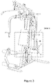
Figure 1 represents the operation of the system for the performance of the exercise without the use of counterweights. -
Figure 2 - detail A - represents the system inserted into already known exercise devices. -
Figure 3 - detail A - represents the enlargement and the demonstration of the system inserted into already known exercise devices. -
Figure 4 represents a rear view of the projection of the system for the performance of exercises attached to the wall. -
Figure 5 represents the front view of the projection of the system for the performance of exercises attached to the wall. - The present invention describes a system (1) for the performance of exercise without the use of counterweights. The system (1) for the performance of exercise without the use of counterweights comprises a microprocessor (2), which determines the operation of the brake (5) based on speed that is predetermined by the user and the instantaneous speed that is being measured by the speed sensor (4), and also, which receives information from the speed sensor (4), from the dynamometer (9) and from the speed selector (11), which operates with a pulley (3). This operation occurs when the speed, after being regulated by the speed selector (11), which can be, for example, a keyboard, an analog potentiometer, + and - buttons, i.e., any type of selector that specifies the intended speed, is being constantly measured by the speed sensor (4), which forwards the information to the microprocessor (2). This, in turn, controls the brake (5) of the pulley (3 or 3'), seeking to maintain the constant rotation speed, previously specified by the speed selector (11), as well as a steel cable (8), containing an installed dynamometer (9), a load sensor, which supplies information regarding the applied force, which is translated and displayed on the digital panel (7). The steel cable (8) is attached to the pulley (3) and connected to the support bar (6), which translates the employed force displayed on the digital panel (7), where a minimum force is required to overcome the resistance of the spring (10).
- The system (1) for the performance of exercise without the use of counterweights is controlled by a microprocessor (2), which receives information from the speed sensor (4) and from the dynamometer (9) and determines the adjustments required to limit the speed of the movement in accordance with the adjustment made by the user, operating with a pulley (3), which is 20 to 60 cm in diameter and has 90 cm to 250 cm of cable. These measures may vary depending on the type of device.
- The operation of the pulley (3) occurs when the speed, after being regulated by the user, is constantly measured by a speed sensor (4). There are several types of speed sensors (4), both analog and digital. An example of a sensor that can be used in the present invention is the optical sensor, which is capable of informing the RPM to the microprocessor (2). In order to facilitate the use in the present invention, the user could have 10 adjustment possibilities, for example, from a very slow movement to a very fast movement.
- This speed sensor (4) forwards the information to the microprocessor (2), which, in turn, controls the brake (5) of the pulley (3 or 3'), in order to keep the rotation speed constant.
- Once the speed of the movement is regulated in the system (1), this is maintained, whatever the force employed by the person performing the exercise. The force limit is related to the capacity of the brake (5). In the present invention, the force is limited, preferably, up to 300 kg, which is more than in the already known equipment. Preferably, the force should be limited up to 400 kg and, more preferably, up to 500 kg, through the dimensioning of the brake (5), such as, for example, placing more electromagnets and/or more braking elements in order to allow a perfect control of the speed. Therefore, the force applied - whether by a child or by a weightlifter - does not alter the speed of movement of the support bar (6) of the system (1).
- The support bar (6) of the system (1) can be directed to exercise any part of the body, preferably the arms or legs. However, it is not limited to these and the system (1) can be used in different exercises.
- The force employed on the support bar (6) of the system (1) of the present invention is translated into kilograms, pounds or any other measure of weight that is available in the International System of Units (SI). This is continuously displayed on a digital panel (7), preferably composed of an LCD screen. It can also be a digital touch screen panel, or analog or similar. It contains information, such as, for example, the speed and weight adjustments, supplied by the microprocessor (2), so that the user can regulate at will the force employed and, therefore, the weight load of his exercise.
- The present invention allows for the load to be programmed and even to be altered by the user, during the exercise, at will. This is because, as the system (1) does not use weights/counterweights, it only uses the control of the speed of the movement of the user, where the force employed in the exercise depends only on the will/capability of the individual.
- Therefore, the user is the person who decides the quantity of force to be employed in the exercise.
- Furthermore, the user can observe the information of the equivalent amount of kilos "lifted" that is displayed on the digital panel (7). This is increased and reduced by the simple determination of the force being employed on the support bar (6), which is measured by the dynamometer (9). Therefore, the "load" is related only to the physical condition of the user, who is entirely capable of increasing or decreasing the force, at will. Therefore, whereas in the conventional systems the user previously regulates the weight and determines the speed of the exercise during its performance, in the present invention the user previously establishes the speed and employs/alters the force at will.
- The brake (5) described here may be a disc, electromagnetic, drum or electro-hydraulic brake, although it is not limited to these. An example of an embodiment of the present invention is the use of the electromagnetic brake, where there is a disk attached to the pulley and two close electromagnets that, when activated, brake the system (1) (Foucault effect).
- The brake (5), such as, for example; the electromagnetic brake, has a load that varies in accordance with the intensity of the electric voltage. Another example of the operation of the system (1) is the action of a disc brake actuated by a stepper motor, which can be a drum brake or similar.
- The entire system (1) described here is controlled by a microprocessor (2), which functions as an interface.
- The microprocessor (2), after receiving the information relating to the speed, controls the use of the brake (5), in order to maintain the constant speed predetermined by the user.
- The microprocessor (2) described here is equivalent to a computer, only that it is very small and is dedicated solely to this task. The microprocessor (2) receives the information from the speed sensor (4), processes the information (based on the determination of the speed made by the user) and determines the action of the components of the system (1).
- The microprocessor (2) is also entirely capable of controlling the stepper motor with minimal movements, which guarantees high precision in the control of the speed of the movement, in the situation of the brakes (5) being operated by the same.
- The system (1) described herein is composed of a computer program - software - (12), which, on the basis of the information received from the speed sensor (4), from the dynamometer (9), and from the speed selector (11), determines the operation of the brake (5), which can act releasing the pulley (3) (rotating below that programmed) or the contrary.
- Only minimal force is required to overcome the resistance of the spring (10) used to bring the system (1) to the initial condition, which is considered negligible. The maximum force is directly related to the brake capacity of the system (1). It can be built for a maximum load of up to 500 kg, as previously described, depending only on the brake (5).
- It is important to observe that using a disk brake, driven by a stepper motor, the capacity of the system (1) is much greater.
- Furthermore, a steel cable (8) attached to the pulley (3) connects with the support bar (6), which is used for the exercise. The steel cable (8) is 3 to 10 mm thick. However, the diameter varies in accordance with the capacity of the system (1) described herein. In the situation of the force to be employed being 500 kg, the steel cable (8) must have a larger diameter.
- A dynamometer (9), also known as a load sensor, installed on the steel cable (8) supplies the information about the applied force, which is translated preferably in kilograms, and is displayed on the digital panel (7). The dynamometer (9) is required to guarantee the safety of the system (1). If there is no force being employed, the system (1) interprets that there is no exercise being practiced and interrupts the operation of the motor and returns everything back to the original position.
- At the end of the exercise, the pulley (3) returns to the original position, due to the spring (10).
- The spring (10) only acts to return the system (1) to the initial position. It is sized to perform only this task, in order to interfere as little as possible during the exercise. One example of a type of spring (10) in the present invention is a spiral spring, taking into account that the pulley (3) can give more than one complete turn. Examples of springs (10) used are, in addition to the spiral spring, a helical or spiral spring, common springs or springs used in conjunction with an electric motor. The size of the spring (10) is proportional to the size of the pulley (3) and it is placed on the opposite side to the brake (5). The spring (10) is attached immediately above the central axis of the pulley (3). The spring (10) has the function of making the system (1) return to the initial position, so that it can be used again.
- Because this is a system (1) that uses a microprocessor (2), integration of the said system (1) is foreseen with other digital systems, such as, for example, computers, tablets and smartphones, etc.
- The system (1) described herein is relatively small, depending basically on the size of the pulley (3). This system (1) can be either coupled to already existing systems of weights -
Figures 2 and3 , for example, professional or domestic bodybuilding stations, or inserted into developed equipment that is designed only for it, where there is a greater integration and design, for example, interaction with smartphones, tablets, use of a coded card (e.g., subway card), biometric recognition (facial or digital) and touch screens, etc. Precisely because it is small and light, the system (1) described herein can be attached directly onto the wall -Figures 4 and 5 - so that the steel cable (8) can be used freely, with an exit point either below or above. It can be seen that, due to the spring (10), the whole system (1) is always stored in an organized manner. Therefore, it is concluded that the entire system (1) may be inside a housing -Figures 4 and 5 - because all the parts can be mounted close to each other, including the speed selector (11) and the digital panel (7) - or only with the digital panel (7) positioned elsewhere. In addition, the digital panel (7) can be removed in order to reduce system costs, whereby the speed selector (11) can be placed in the housing itself, in a single unit. - Preferential examples of speed selectors (11) are the following selectors: digital or analog, those with a keyboard, potentiometer, buttons and speed controls activated remotely that can be performed by a remote control, smartphones and similar devices.
- Therefore, this housing can be fixed onto the wall or any other base, at whatever height the user wants -
Figures 4 and 5 . For greater convenience, the housing may also be supplied with an extra pulley (3') at the exit point of the steel cable (8), in order to direct it horizontally. In this way, it is a system (1) that fits into one housing, making it a practical and useful system (1). - Finally, another example is the operation of the entire system (1) only as electric motors, in order to maintain the basic principle of the system (1) based on the idea of speed and force. With this, the use of the brake (5), the speed sensor (4), and the dynamometer (9) is not required. What is required in order to guarantee the safety of the system (1) is only the use of the digital panel (7) and the speed selector (11). If there is no force being employed, the system (1) interprets that there is no exercise being practiced and interrupts the operation of the motor and returns everything back to the original position.
- The system (1) can also be assembled based on an electric motor, coupled or not, to a gearbox, in order to provide a high torque. In this situation, specific software takes care of maintaining the central idea of the system (1), which is the constant speed of the movement, independent of the force employed by the user. The speed selector (11), the dynamometer (9) and the digital panel (7) would be maintained with all the information described previously. In this situation, there is the possibility of the performance of the eccentric movement, simply by reversing the rotation of the motor, in addition to the performance of the concentric movement, which is identical to the previously described mechanical system.
Claims (5)
- A system (1), for the performance of exercise,wherein the system (1) comprises a microprocessor (2), a pulley (3), a speed sensor (4), a brake (5), a support bar (6), a digital panel (7), a steel cable (8), a dynamometer (9), a spring (10), and a speed selector (11),wherein the steel cable (8) is attached to the pulley (3) and connected to the support bar (6),andwherein the spring (10) is attached immediately above the central axis to the pulley (3) and, in order to overcome the resistance of the spring (10), a minimum force must be applied to the support bar (6),- based on a determination of the speed made by a user, the speed selector (11) is configured to specify the constant rotation speed, wherein the microprocessor (2) is configured to maintain the constant rotation speed as specified by the speed selector,- the dynamometer (9) is configured to supply information about applied force to the steel cable (8) to the microprocessor (2),- the speed sensor (4) is configured to constantly measure an instantaneous rotation speed of the pulley (3) and to forward said instantaneous rotation speed information to the microprocessor (2),- the microprocessor (12) which based on the received information from the speed selector (11) and on the received information from the
sensors (4, 9), is configured to determine an operation of the brake (5) of the pulley (3) in order to maintain a constant rotation speed of the pulley (3), so that the speed of movement of the support bar (6) is maintained constant,• wherein the brake (5) acts by releasing the pulley (3) when it rotates below the programmed speed, or• wherein the brake (5) acts by being applied on the pulley (3) when it rotates above the programmed speed,- wherein the brake (5) is a disc, electromagnetic, drum or electro-hydraulic brake,- wherein the dynamometer (9) is installed on the steel cable (8), and- the dynamometer (9) configured to supply information about the applied force to the digital panel (7), which digital panel (7) is configured to display the applied force. - System (1) in accordance with Claim 1, characterized in that it comprises a second pulley (3').
- System (1) in accordance with any one of the previous Claims, characterized in that the brake (5) has a capacity for a force of up to 500 kg.
- System (1) in accordance with any one of the previous Claims, characterized in that the spring (10) is helical or spiral and is configured to bring the system (1) back to its initial status.
- System (1) in accordance with any one of the previous Claims, characterized in that the speed selector (11) is a digital selector, an analog selector, selector with a keyboard, a potentiometer, buttons, a touchscreen display, or a speed controls selector actioned remotely.
Priority Applications (2)
| Application Number | Priority Date | Filing Date | Title |
|---|---|---|---|
| EP20194662.1A EP3808414A1 (en) | 2016-06-21 | 2017-01-24 | Exercise device system |
| PL17814344T PL3473303T3 (en) | 2016-06-21 | 2017-01-24 | Microprocessor-controlled system for human physical training |
Applications Claiming Priority (2)
| Application Number | Priority Date | Filing Date | Title |
|---|---|---|---|
| BR102016014608A BR102016014608B1 (en) | 2016-06-21 | 2016-06-21 | exercise device system |
| PCT/BR2017/000005 WO2017219103A1 (en) | 2016-06-21 | 2017-01-24 | Microprocessor-controlled system for human physical training |
Related Child Applications (2)
| Application Number | Title | Priority Date | Filing Date |
|---|---|---|---|
| EP20194662.1A Division EP3808414A1 (en) | 2016-06-21 | 2017-01-24 | Exercise device system |
| EP20194662.1A Division-Into EP3808414A1 (en) | 2016-06-21 | 2017-01-24 | Exercise device system |
Publications (3)
| Publication Number | Publication Date |
|---|---|
| EP3473303A1 EP3473303A1 (en) | 2019-04-24 |
| EP3473303A4 EP3473303A4 (en) | 2020-03-04 |
| EP3473303B1 true EP3473303B1 (en) | 2022-04-20 |
Family
ID=60783169
Family Applications (2)
| Application Number | Title | Priority Date | Filing Date |
|---|---|---|---|
| EP20194662.1A Withdrawn EP3808414A1 (en) | 2016-06-21 | 2017-01-24 | Exercise device system |
| EP17814344.2A Active EP3473303B1 (en) | 2016-06-21 | 2017-01-24 | Microprocessor-controlled system for human physical training |
Family Applications Before (1)
| Application Number | Title | Priority Date | Filing Date |
|---|---|---|---|
| EP20194662.1A Withdrawn EP3808414A1 (en) | 2016-06-21 | 2017-01-24 | Exercise device system |
Country Status (13)
| Country | Link |
|---|---|
| US (1) | US10953266B2 (en) |
| EP (2) | EP3808414A1 (en) |
| JP (1) | JP6735856B2 (en) |
| KR (1) | KR102770666B1 (en) |
| CN (1) | CN109562288B (en) |
| BR (1) | BR102016014608B1 (en) |
| CA (1) | CA3029250C (en) |
| DK (1) | DK3473303T3 (en) |
| ES (1) | ES2912616T3 (en) |
| MX (1) | MX386869B (en) |
| PL (1) | PL3473303T3 (en) |
| PT (1) | PT3473303T (en) |
| WO (1) | WO2017219103A1 (en) |
Families Citing this family (33)
| Publication number | Priority date | Publication date | Assignee | Title |
|---|---|---|---|---|
| US11745039B2 (en) | 2016-07-25 | 2023-09-05 | Tonal Systems, Inc. | Assisted racking of digital resistance |
| US10661112B2 (en) | 2016-07-25 | 2020-05-26 | Tonal Systems, Inc. | Digital strength training |
| US10335626B2 (en) | 2017-10-02 | 2019-07-02 | Tonal Systems, Inc. | Exercise machine with pancake motor |
| US10617903B2 (en) | 2017-10-02 | 2020-04-14 | Tonal Systems, Inc. | Exercise machine differential |
| US10486015B2 (en) | 2017-10-02 | 2019-11-26 | Tonal Systems, Inc. | Exercise machine enhancements |
| US10589163B2 (en) | 2017-10-02 | 2020-03-17 | Tonal Systems, Inc. | Exercise machine safety enhancements |
| US12239871B1 (en) | 2018-03-29 | 2025-03-04 | Quickhit International, Inc. | Exercise equipment and systems |
| US10814172B1 (en) * | 2018-03-29 | 2020-10-27 | Quickhit International, Inc. | Exercise equipment and systems |
| AU2020345648A1 (en) * | 2019-09-10 | 2022-04-21 | Vitruvian Investments Pty Ltd | Fitness training apparatus and system |
| US20210077849A1 (en) * | 2019-09-13 | 2021-03-18 | Vertimax, Llc | Smart pulley |
| US11759691B2 (en) * | 2019-11-14 | 2023-09-19 | Destro Machines LLC | Tethered resistance swim training apparatus with smart pulley |
| USD952074S1 (en) | 2020-01-16 | 2022-05-17 | Peloton Interactive, Inc. | Leg extension exercise machine |
| USD949262S1 (en) | 2020-01-16 | 2022-04-19 | Peloton Interactive, Inc. | Shroud of a fitness equipment unit |
| USD952076S1 (en) | 2020-01-16 | 2022-05-17 | Peloton Interactive, Inc. | Leg curl exercise machine |
| USD952072S1 (en) | 2020-01-16 | 2022-05-17 | Peloton Interactive, Inc. | Bicep curl exercise machine |
| USD952077S1 (en) * | 2020-01-16 | 2022-05-17 | Peloton Interactive, Inc. | Rear, delt and pec fly exercise machine |
| USD952073S1 (en) * | 2020-01-16 | 2022-05-17 | Peloton Interactive, Inc. | Chest press exercise machine |
| USD952777S1 (en) * | 2020-01-16 | 2022-05-24 | Peloton Interactive, Inc. | Abdominal exercise machine |
| USD952075S1 (en) | 2020-01-16 | 2022-05-17 | Peloton Interactive, Inc. | Leg press exercise machine |
| USD949263S1 (en) | 2020-01-16 | 2022-04-19 | Peloton Interactive, Inc. | Weight stack selector elements of an exercise machine |
| US11285355B1 (en) * | 2020-06-08 | 2022-03-29 | Tonal Systems, Inc. | Exercise machine enhancements |
| US12151135B2 (en) | 2020-06-12 | 2024-11-26 | Thorux Corp. | Electric motor based physical training technology and devices |
| CN112386858B (en) * | 2020-11-12 | 2022-04-01 | 浙大宁波理工学院 | Comprehensive body-building device capable of stepless regulating resistance |
| CN116829232A (en) * | 2020-12-15 | 2023-09-29 | 托纳系统公司 | Floor-based exercise machine construction |
| WO2022179787A1 (en) * | 2021-02-26 | 2022-09-01 | Nicolai Bode | Training device for isokinetic power training |
| US11878204B2 (en) | 2021-04-27 | 2024-01-23 | Tonal Systems, Inc. | First repetition detection |
| US11998804B2 (en) | 2021-04-27 | 2024-06-04 | Tonal Systems, Inc. | Repetition phase detection |
| TWM623726U (en) * | 2021-10-27 | 2022-02-21 | 優至俙健康科技有限公司 | Electrically controlled resistance device for muscle strength training |
| US11596837B1 (en) * | 2022-01-11 | 2023-03-07 | Tonal Systems, Inc. | Exercise machine suggested weights |
| CN114739715B (en) * | 2022-05-10 | 2025-03-14 | 昆山龙雨智能科技有限公司 | A fitness tensile machine testing equipment |
| USD989894S1 (en) | 2022-11-08 | 2023-06-20 | Gavin Edward Hamer | Sliding exercise and measurement device |
| US12521588B2 (en) * | 2024-04-19 | 2026-01-13 | Marius Popescu | Exercise apparatus using bidirectional adaptive resistance |
| WO2026029717A1 (en) | 2024-07-29 | 2026-02-05 | Agrebi Brahim | Ballistic training and rehabilitation device for shoulders and arms, providing instant throwing variables feedback |
Family Cites Families (42)
| Publication number | Priority date | Publication date | Assignee | Title |
|---|---|---|---|---|
| US3869121A (en) * | 1972-07-10 | 1975-03-04 | Evan R Flavell | Proportioned resistance exercise servo system |
| US4778175A (en) * | 1986-09-02 | 1988-10-18 | The Toro Company | Electronic control of resistance force for exercise machine |
| US4772015A (en) | 1987-04-23 | 1988-09-20 | The Toro Company | Shoulder and arm exercise machine |
| US4919418A (en) * | 1988-01-27 | 1990-04-24 | Miller Jan W | Computerized drive mechanism for exercise, physical therapy and rehabilitation |
| FI85224C (en) * | 1990-08-23 | 1992-03-25 | Tunturipyoerae Oy | resistance mechanism |
| WO1993005711A1 (en) * | 1991-09-16 | 1993-04-01 | Alaska Research And Development, Inc. | Exercise platform for physiological testing |
| US5318491A (en) * | 1992-10-19 | 1994-06-07 | Vincent Houston | Multiple mode tug of war exercise machine |
| US5328429A (en) * | 1993-05-20 | 1994-07-12 | Computer Sports Medicine, Inc. | Asymmetric force applicator attachment for weight stack type exercise machines |
| CA2164096A1 (en) * | 1993-06-02 | 1994-12-08 | Ted R. Ehrenfried | Electromechanical resistance exercise apparatus |
| US5435798A (en) * | 1993-08-17 | 1995-07-25 | Pacific Fitness Corporation | Exercise apparatus with electronically variable resistance |
| US5409435A (en) * | 1993-11-03 | 1995-04-25 | Daniels; John J. | Variable resistance exercise device |
| US5569120A (en) * | 1994-06-24 | 1996-10-29 | University Of Maryland-Baltimore County | Method of using and apparatus for use with exercise machines to achieve programmable variable resistance |
| US6280361B1 (en) | 2000-02-03 | 2001-08-28 | Intelligent Automation, Inc. | Computerized exercise system and method |
| WO2007043970A1 (en) * | 2005-10-12 | 2007-04-19 | Sensyact Ab | A method, a computer program and a device for controlling a movable resistance element in a training device |
| GB2436324A (en) * | 2006-03-20 | 2007-09-26 | Drop Zone Uk Ltd | Windage Braking |
| US20110172058A1 (en) * | 2008-08-22 | 2011-07-14 | Stelu Deaconu | Variable resistance adaptive exercise apparatus and method of use thereof |
| CN100577241C (en) * | 2008-10-31 | 2010-01-06 | 上海工程技术大学 | Indoor Climbing Safety Devices |
| WO2010123948A2 (en) * | 2009-04-20 | 2010-10-28 | Joseph Turner | Exercise machine for providing resistance to ambulatory motion of the user |
| KR101112709B1 (en) * | 2009-06-12 | 2012-02-24 | 임정수 | Aerobic exercise machine for the upper part of human body |
| GB201108398D0 (en) * | 2011-05-19 | 2011-07-06 | Loach Andrew | Hand-held exercise apparatus and resistance mechanism for exercise apparatus |
| US8845499B1 (en) * | 2011-12-09 | 2014-09-30 | Donald Jeffrey Boatwright | Personal force resistance cable exercise device, force resistance assembly, and method of exercising |
| US10143880B1 (en) * | 2011-12-09 | 2018-12-04 | Donald Jeffrey Boatwright | Cable exercise device and method |
| DE102011121259B3 (en) * | 2011-12-15 | 2013-05-16 | Fabian Walke | Method and device for mobile training data acquisition and analysis of strength training |
| BR102012011320A2 (en) | 2012-05-14 | 2014-04-15 | Anderson Rios Sodeyama | Counterforce system for eccentric exercise equipment |
| US8968155B2 (en) * | 2012-07-31 | 2015-03-03 | John M. Bird | Resistance apparatus, system, and method |
| US9254409B2 (en) * | 2013-03-14 | 2016-02-09 | Icon Health & Fitness, Inc. | Strength training apparatus with flywheel and related methods |
| US20140287876A1 (en) | 2013-03-15 | 2014-09-25 | Dana V. Etter | Continuously variable resistance exercise system |
| CN203539973U (en) | 2013-07-16 | 2014-04-16 | 山西安鸿健身器材有限公司 | Counterweight block for bodybuilding device |
| GB201313214D0 (en) * | 2013-07-24 | 2013-09-04 | Intelligent Resistance Ltd | Assembly for applying a force |
| EP3623020B1 (en) * | 2013-12-26 | 2024-05-01 | iFIT Inc. | Magnetic resistance mechanism in a cable machine |
| US20150258361A1 (en) * | 2014-03-11 | 2015-09-17 | Grant Electronic Limited | Pull Training Device |
| US9586089B2 (en) * | 2014-06-17 | 2017-03-07 | Lagree Technologies, Inc. | Exercise machine adjustable resistance system and method |
| US20150367162A1 (en) * | 2014-06-23 | 2015-12-24 | Peter A. Mueller | Weight adjustment by means of a ramp |
| CN104138652B (en) | 2014-07-14 | 2016-04-13 | 湖北欧阳劲潮体育科技有限公司 | A kind of magnetic torsion source sitting posture leg extensions training aids |
| US9724563B2 (en) * | 2014-10-27 | 2017-08-08 | Schmidt Design, Llc | User interface for a motorized isokinetic resistance exercise machine |
| WO2016069471A1 (en) * | 2014-10-31 | 2016-05-06 | BACH, James, Christopher | Exercice device with pneumatic resistance |
| WO2016079389A1 (en) * | 2014-11-19 | 2016-05-26 | Technologie Et Developpement Industriel | Exercise and/or rehabilitation apparatus |
| US20180214730A1 (en) * | 2015-08-24 | 2018-08-02 | Exonetik Inc. | Strength training device using magnetorheological fluid clutch apparatus |
| EP3452185A2 (en) * | 2016-05-04 | 2019-03-13 | Nautilus, Inc. | Exercise machine and user interface for exercise machine |
| WO2018140959A1 (en) * | 2017-01-30 | 2018-08-02 | Liftlab, Inc | Systems for dynamic resistance training |
| US20180339196A1 (en) * | 2017-05-26 | 2018-11-29 | Cleveland State University | Powered machine and control method |
| US11191989B2 (en) * | 2017-10-26 | 2021-12-07 | Schmidt Design, Llc | Safety control system for motorized resistance equipment utilizing one-way clutches |
-
2016
- 2016-06-21 BR BR102016014608A patent/BR102016014608B1/en active IP Right Grant
-
2017
- 2017-01-24 EP EP20194662.1A patent/EP3808414A1/en not_active Withdrawn
- 2017-01-24 EP EP17814344.2A patent/EP3473303B1/en active Active
- 2017-01-24 ES ES17814344T patent/ES2912616T3/en active Active
- 2017-01-24 KR KR1020197000415A patent/KR102770666B1/en active Active
- 2017-01-24 DK DK17814344.2T patent/DK3473303T3/en active
- 2017-01-24 WO PCT/BR2017/000005 patent/WO2017219103A1/en not_active Ceased
- 2017-01-24 PL PL17814344T patent/PL3473303T3/en unknown
- 2017-01-24 PT PT178143442T patent/PT3473303T/en unknown
- 2017-01-24 MX MX2018015025A patent/MX386869B/en unknown
- 2017-01-24 JP JP2018566549A patent/JP6735856B2/en active Active
- 2017-01-24 CA CA3029250A patent/CA3029250C/en active Active
- 2017-01-24 CN CN201780038256.3A patent/CN109562288B/en active Active
- 2017-01-24 US US16/309,553 patent/US10953266B2/en active Active
Also Published As
| Publication number | Publication date |
|---|---|
| CA3029250C (en) | 2024-02-20 |
| US20190160324A1 (en) | 2019-05-30 |
| DK3473303T3 (en) | 2022-05-16 |
| KR20190020021A (en) | 2019-02-27 |
| US10953266B2 (en) | 2021-03-23 |
| CA3029250A1 (en) | 2017-12-28 |
| CN109562288B (en) | 2021-06-29 |
| CN109562288A (en) | 2019-04-02 |
| KR102770666B1 (en) | 2025-02-24 |
| MX386869B (en) | 2025-03-19 |
| EP3473303A4 (en) | 2020-03-04 |
| JP6735856B2 (en) | 2020-08-05 |
| EP3473303A1 (en) | 2019-04-24 |
| PT3473303T (en) | 2022-05-11 |
| BR102016014608A2 (en) | 2018-01-09 |
| BR102016014608B1 (en) | 2020-01-21 |
| PL3473303T3 (en) | 2022-06-13 |
| MX2018015025A (en) | 2019-08-14 |
| JP2019518556A (en) | 2019-07-04 |
| EP3808414A1 (en) | 2021-04-21 |
| WO2017219103A1 (en) | 2017-12-28 |
| ES2912616T3 (en) | 2022-05-26 |
Similar Documents
| Publication | Publication Date | Title |
|---|---|---|
| EP3473303B1 (en) | Microprocessor-controlled system for human physical training | |
| EP3341087B1 (en) | Weights system | |
| CN106470739B (en) | Cable system incorporated into the treadmill | |
| KR101923867B1 (en) | Personal fitness machine device using VR | |
| JP7370480B2 (en) | dynamic exercise resistance module | |
| US20140287876A1 (en) | Continuously variable resistance exercise system | |
| US20100311552A1 (en) | Vibrationary exercise equipment | |
| KR101677845B1 (en) | Smart dumbbell device | |
| EP3439753A1 (en) | Interactive apparatus and methods for muscle strengthening | |
| KR101375810B1 (en) | Training machine and weight control device using the same | |
| US20130274077A1 (en) | Motion mechanism in a weight device | |
| KR100870720B1 (en) | Electro-hydraulic exercise equipment | |
| US20220072367A1 (en) | Pull-up fitness exercise machine with remote intelligent control device | |
| JP4949410B2 (en) | Exercise treadmill for towing and tensioning | |
| GB2259864A (en) | Exercising device | |
| EP4454627A1 (en) | Physiotherapy treatment device | |
| HK40103234A (en) | Method for adjusting standard and dynamic torque-to- linear forces in real time | |
| WO2025168291A1 (en) | Training apparatus for bidirectional loads | |
| KR100483286B1 (en) | Controling method for sporting goods having vibrator | |
| HK40082192A (en) | Modular and dynamic force apparatus | |
| HK1184094A (en) | A motion mechanism in a weight device |
Legal Events
| Date | Code | Title | Description |
|---|---|---|---|
| STAA | Information on the status of an ep patent application or granted ep patent |
Free format text: STATUS: THE INTERNATIONAL PUBLICATION HAS BEEN MADE |
|
| PUAI | Public reference made under article 153(3) epc to a published international application that has entered the european phase |
Free format text: ORIGINAL CODE: 0009012 |
|
| STAA | Information on the status of an ep patent application or granted ep patent |
Free format text: STATUS: REQUEST FOR EXAMINATION WAS MADE |
|
| 17P | Request for examination filed |
Effective date: 20181221 |
|
| AK | Designated contracting states |
Kind code of ref document: A1 Designated state(s): AL AT BE BG CH CY CZ DE DK EE ES FI FR GB GR HR HU IE IS IT LI LT LU LV MC MK MT NL NO PL PT RO RS SE SI SK SM TR |
|
| AX | Request for extension of the european patent |
Extension state: BA ME |
|
| DAV | Request for validation of the european patent (deleted) | ||
| DAX | Request for extension of the european patent (deleted) | ||
| A4 | Supplementary search report drawn up and despatched |
Effective date: 20200131 |
|
| RIC1 | Information provided on ipc code assigned before grant |
Ipc: A63B 71/06 20060101ALI20200127BHEP Ipc: A63B 24/00 20060101ALI20200127BHEP Ipc: A61B 5/22 20060101ALI20200127BHEP Ipc: A63B 21/02 20060101ALI20200127BHEP Ipc: A63B 21/00 20060101AFI20200127BHEP Ipc: A63B 21/002 20060101ALI20200127BHEP Ipc: A63B 21/008 20060101ALI20200127BHEP Ipc: G05B 19/048 20060101ALI20200127BHEP Ipc: A63B 21/015 20060101ALI20200127BHEP Ipc: G01L 1/00 20060101ALI20200127BHEP Ipc: A63B 21/005 20060101ALI20200127BHEP |
|
| STAA | Information on the status of an ep patent application or granted ep patent |
Free format text: STATUS: EXAMINATION IS IN PROGRESS |
|
| 17Q | First examination report despatched |
Effective date: 20201216 |
|
| GRAP | Despatch of communication of intention to grant a patent |
Free format text: ORIGINAL CODE: EPIDOSNIGR1 |
|
| STAA | Information on the status of an ep patent application or granted ep patent |
Free format text: STATUS: GRANT OF PATENT IS INTENDED |
|
| INTG | Intention to grant announced |
Effective date: 20211108 |
|
| GRAS | Grant fee paid |
Free format text: ORIGINAL CODE: EPIDOSNIGR3 |
|
| GRAA | (expected) grant |
Free format text: ORIGINAL CODE: 0009210 |
|
| STAA | Information on the status of an ep patent application or granted ep patent |
Free format text: STATUS: THE PATENT HAS BEEN GRANTED |
|
| AK | Designated contracting states |
Kind code of ref document: B1 Designated state(s): AL AT BE BG CH CY CZ DE DK EE ES FI FR GB GR HR HU IE IS IT LI LT LU LV MC MK MT NL NO PL PT RO RS SE SI SK SM TR |
|
| REG | Reference to a national code |
Ref country code: GB Ref legal event code: FG4D |
|
| REG | Reference to a national code |
Ref country code: CH Ref legal event code: EP |
|
| REG | Reference to a national code |
Ref country code: IE Ref legal event code: FG4D Ref country code: PT Ref legal event code: SC4A Ref document number: 3473303 Country of ref document: PT Date of ref document: 20220511 Kind code of ref document: T Free format text: AVAILABILITY OF NATIONAL TRANSLATION Effective date: 20220504 |
|
| REG | Reference to a national code |
Ref country code: DE Ref legal event code: R096 Ref document number: 602017056314 Country of ref document: DE |
|
| REG | Reference to a national code |
Ref country code: AT Ref legal event code: REF Ref document number: 1484720 Country of ref document: AT Kind code of ref document: T Effective date: 20220515 |
|
| REG | Reference to a national code |
Ref country code: DK Ref legal event code: T3 Effective date: 20220509 |
|
| REG | Reference to a national code |
Ref country code: NL Ref legal event code: FP |
|
| REG | Reference to a national code |
Ref country code: ES Ref legal event code: FG2A Ref document number: 2912616 Country of ref document: ES Kind code of ref document: T3 Effective date: 20220526 |
|
| REG | Reference to a national code |
Ref country code: SE Ref legal event code: TRGR |
|
| REG | Reference to a national code |
Ref country code: NO Ref legal event code: T2 Effective date: 20220420 |
|
| REG | Reference to a national code |
Ref country code: LT Ref legal event code: MG9D |
|
| REG | Reference to a national code |
Ref country code: AT Ref legal event code: MK05 Ref document number: 1484720 Country of ref document: AT Kind code of ref document: T Effective date: 20220420 |
|
| PG25 | Lapsed in a contracting state [announced via postgrant information from national office to epo] |
Ref country code: LT Free format text: LAPSE BECAUSE OF FAILURE TO SUBMIT A TRANSLATION OF THE DESCRIPTION OR TO PAY THE FEE WITHIN THE PRESCRIBED TIME-LIMIT Effective date: 20220420 Ref country code: HR Free format text: LAPSE BECAUSE OF FAILURE TO SUBMIT A TRANSLATION OF THE DESCRIPTION OR TO PAY THE FEE WITHIN THE PRESCRIBED TIME-LIMIT Effective date: 20220420 Ref country code: GR Free format text: LAPSE BECAUSE OF FAILURE TO SUBMIT A TRANSLATION OF THE DESCRIPTION OR TO PAY THE FEE WITHIN THE PRESCRIBED TIME-LIMIT Effective date: 20220721 Ref country code: FI Free format text: LAPSE BECAUSE OF FAILURE TO SUBMIT A TRANSLATION OF THE DESCRIPTION OR TO PAY THE FEE WITHIN THE PRESCRIBED TIME-LIMIT Effective date: 20220420 Ref country code: BG Free format text: LAPSE BECAUSE OF FAILURE TO SUBMIT A TRANSLATION OF THE DESCRIPTION OR TO PAY THE FEE WITHIN THE PRESCRIBED TIME-LIMIT Effective date: 20220720 Ref country code: AT Free format text: LAPSE BECAUSE OF FAILURE TO SUBMIT A TRANSLATION OF THE DESCRIPTION OR TO PAY THE FEE WITHIN THE PRESCRIBED TIME-LIMIT Effective date: 20220420 |
|
| PG25 | Lapsed in a contracting state [announced via postgrant information from national office to epo] |
Ref country code: RS Free format text: LAPSE BECAUSE OF FAILURE TO SUBMIT A TRANSLATION OF THE DESCRIPTION OR TO PAY THE FEE WITHIN THE PRESCRIBED TIME-LIMIT Effective date: 20220420 Ref country code: LV Free format text: LAPSE BECAUSE OF FAILURE TO SUBMIT A TRANSLATION OF THE DESCRIPTION OR TO PAY THE FEE WITHIN THE PRESCRIBED TIME-LIMIT Effective date: 20220420 Ref country code: IS Free format text: LAPSE BECAUSE OF FAILURE TO SUBMIT A TRANSLATION OF THE DESCRIPTION OR TO PAY THE FEE WITHIN THE PRESCRIBED TIME-LIMIT Effective date: 20220820 |
|
| REG | Reference to a national code |
Ref country code: DE Ref legal event code: R097 Ref document number: 602017056314 Country of ref document: DE |
|
| PG25 | Lapsed in a contracting state [announced via postgrant information from national office to epo] |
Ref country code: SM Free format text: LAPSE BECAUSE OF FAILURE TO SUBMIT A TRANSLATION OF THE DESCRIPTION OR TO PAY THE FEE WITHIN THE PRESCRIBED TIME-LIMIT Effective date: 20220420 Ref country code: SK Free format text: LAPSE BECAUSE OF FAILURE TO SUBMIT A TRANSLATION OF THE DESCRIPTION OR TO PAY THE FEE WITHIN THE PRESCRIBED TIME-LIMIT Effective date: 20220420 Ref country code: RO Free format text: LAPSE BECAUSE OF FAILURE TO SUBMIT A TRANSLATION OF THE DESCRIPTION OR TO PAY THE FEE WITHIN THE PRESCRIBED TIME-LIMIT Effective date: 20220420 Ref country code: EE Free format text: LAPSE BECAUSE OF FAILURE TO SUBMIT A TRANSLATION OF THE DESCRIPTION OR TO PAY THE FEE WITHIN THE PRESCRIBED TIME-LIMIT Effective date: 20220420 Ref country code: CZ Free format text: LAPSE BECAUSE OF FAILURE TO SUBMIT A TRANSLATION OF THE DESCRIPTION OR TO PAY THE FEE WITHIN THE PRESCRIBED TIME-LIMIT Effective date: 20220420 |
|
| PLBE | No opposition filed within time limit |
Free format text: ORIGINAL CODE: 0009261 |
|
| STAA | Information on the status of an ep patent application or granted ep patent |
Free format text: STATUS: NO OPPOSITION FILED WITHIN TIME LIMIT |
|
| 26N | No opposition filed |
Effective date: 20230123 |
|
| PG25 | Lapsed in a contracting state [announced via postgrant information from national office to epo] |
Ref country code: AL Free format text: LAPSE BECAUSE OF FAILURE TO SUBMIT A TRANSLATION OF THE DESCRIPTION OR TO PAY THE FEE WITHIN THE PRESCRIBED TIME-LIMIT Effective date: 20220420 |
|
| PG25 | Lapsed in a contracting state [announced via postgrant information from national office to epo] |
Ref country code: SI Free format text: LAPSE BECAUSE OF FAILURE TO SUBMIT A TRANSLATION OF THE DESCRIPTION OR TO PAY THE FEE WITHIN THE PRESCRIBED TIME-LIMIT Effective date: 20220420 |
|
| REG | Reference to a national code |
Ref country code: CH Ref legal event code: PL |
|
| PG25 | Lapsed in a contracting state [announced via postgrant information from national office to epo] |
Ref country code: LU Free format text: LAPSE BECAUSE OF NON-PAYMENT OF DUE FEES Effective date: 20230124 |
|
| PG25 | Lapsed in a contracting state [announced via postgrant information from national office to epo] |
Ref country code: LI Free format text: LAPSE BECAUSE OF NON-PAYMENT OF DUE FEES Effective date: 20230131 Ref country code: CH Free format text: LAPSE BECAUSE OF NON-PAYMENT OF DUE FEES Effective date: 20230131 |
|
| PG25 | Lapsed in a contracting state [announced via postgrant information from national office to epo] |
Ref country code: MC Free format text: LAPSE BECAUSE OF FAILURE TO SUBMIT A TRANSLATION OF THE DESCRIPTION OR TO PAY THE FEE WITHIN THE PRESCRIBED TIME-LIMIT Effective date: 20220420 |
|
| PG25 | Lapsed in a contracting state [announced via postgrant information from national office to epo] |
Ref country code: MC Free format text: LAPSE BECAUSE OF FAILURE TO SUBMIT A TRANSLATION OF THE DESCRIPTION OR TO PAY THE FEE WITHIN THE PRESCRIBED TIME-LIMIT Effective date: 20220420 |
|
| PG25 | Lapsed in a contracting state [announced via postgrant information from national office to epo] |
Ref country code: BG Free format text: LAPSE BECAUSE OF FAILURE TO SUBMIT A TRANSLATION OF THE DESCRIPTION OR TO PAY THE FEE WITHIN THE PRESCRIBED TIME-LIMIT Effective date: 20220420 |
|
| PG25 | Lapsed in a contracting state [announced via postgrant information from national office to epo] |
Ref country code: BG Free format text: LAPSE BECAUSE OF FAILURE TO SUBMIT A TRANSLATION OF THE DESCRIPTION OR TO PAY THE FEE WITHIN THE PRESCRIBED TIME-LIMIT Effective date: 20220420 |
|
| PG25 | Lapsed in a contracting state [announced via postgrant information from national office to epo] |
Ref country code: CY Free format text: LAPSE BECAUSE OF FAILURE TO SUBMIT A TRANSLATION OF THE DESCRIPTION OR TO PAY THE FEE WITHIN THE PRESCRIBED TIME-LIMIT; INVALID AB INITIO Effective date: 20170124 |
|
| PG25 | Lapsed in a contracting state [announced via postgrant information from national office to epo] |
Ref country code: HU Free format text: LAPSE BECAUSE OF FAILURE TO SUBMIT A TRANSLATION OF THE DESCRIPTION OR TO PAY THE FEE WITHIN THE PRESCRIBED TIME-LIMIT; INVALID AB INITIO Effective date: 20170124 |
|
| PG25 | Lapsed in a contracting state [announced via postgrant information from national office to epo] |
Ref country code: TR Free format text: LAPSE BECAUSE OF FAILURE TO SUBMIT A TRANSLATION OF THE DESCRIPTION OR TO PAY THE FEE WITHIN THE PRESCRIBED TIME-LIMIT Effective date: 20220420 |
|
| PGFP | Annual fee paid to national office [announced via postgrant information from national office to epo] |
Ref country code: NL Payment date: 20260126 Year of fee payment: 10 |
|
| PGFP | Annual fee paid to national office [announced via postgrant information from national office to epo] |
Ref country code: SE Payment date: 20260127 Year of fee payment: 10 |
|
| PGFP | Annual fee paid to national office [announced via postgrant information from national office to epo] |
Ref country code: GB Payment date: 20260127 Year of fee payment: 10 |
|
| PGFP | Annual fee paid to national office [announced via postgrant information from national office to epo] |
Ref country code: ES Payment date: 20260202 Year of fee payment: 10 |
|
| PGFP | Annual fee paid to national office [announced via postgrant information from national office to epo] |
Ref country code: DE Payment date: 20260128 Year of fee payment: 10 Ref country code: NO Payment date: 20260128 Year of fee payment: 10 Ref country code: DK Payment date: 20260126 Year of fee payment: 10 Ref country code: IE Payment date: 20260127 Year of fee payment: 10 |
|
| PGFP | Annual fee paid to national office [announced via postgrant information from national office to epo] |
Ref country code: BE Payment date: 20260127 Year of fee payment: 10 Ref country code: IT Payment date: 20260121 Year of fee payment: 10 |
|
| PGFP | Annual fee paid to national office [announced via postgrant information from national office to epo] |
Ref country code: FR Payment date: 20260126 Year of fee payment: 10 |
|
| PGFP | Annual fee paid to national office [announced via postgrant information from national office to epo] |
Ref country code: PT Payment date: 20260108 Year of fee payment: 10 |
|
| PGFP | Annual fee paid to national office [announced via postgrant information from national office to epo] |
Ref country code: PL Payment date: 20260102 Year of fee payment: 10 |