EP3473306B1 - Sports ball and method of manufacturing sports ball - Google Patents
Sports ball and method of manufacturing sports ball Download PDFInfo
- Publication number
- EP3473306B1 EP3473306B1 EP18198812.2A EP18198812A EP3473306B1 EP 3473306 B1 EP3473306 B1 EP 3473306B1 EP 18198812 A EP18198812 A EP 18198812A EP 3473306 B1 EP3473306 B1 EP 3473306B1
- Authority
- EP
- European Patent Office
- Prior art keywords
- lining layer
- approximately
- sports ball
- bladder
- carcass
- Prior art date
- Legal status (The legal status is an assumption and is not a legal conclusion. Google has not performed a legal analysis and makes no representation as to the accuracy of the status listed.)
- Active
Links
Images


Classifications
-
- A—HUMAN NECESSITIES
- A63—SPORTS; GAMES; AMUSEMENTS
- A63B—APPARATUS FOR PHYSICAL TRAINING, GYMNASTICS, SWIMMING, CLIMBING, OR FENCING; BALL GAMES; TRAINING EQUIPMENT
- A63B41/00—Hollow inflatable balls
- A63B41/08—Ball covers; Closures therefor
-
- A—HUMAN NECESSITIES
- A63—SPORTS; GAMES; AMUSEMENTS
- A63B—APPARATUS FOR PHYSICAL TRAINING, GYMNASTICS, SWIMMING, CLIMBING, OR FENCING; BALL GAMES; TRAINING EQUIPMENT
- A63B41/00—Hollow inflatable balls
- A63B41/02—Bladders
- A63B41/04—Closures therefor
-
- A—HUMAN NECESSITIES
- A63—SPORTS; GAMES; AMUSEMENTS
- A63B—APPARATUS FOR PHYSICAL TRAINING, GYMNASTICS, SWIMMING, CLIMBING, OR FENCING; BALL GAMES; TRAINING EQUIPMENT
- A63B45/00—Apparatus or methods for manufacturing balls
-
- B—PERFORMING OPERATIONS; TRANSPORTING
- B32—LAYERED PRODUCTS
- B32B—LAYERED PRODUCTS, i.e. PRODUCTS BUILT-UP OF STRATA OF FLAT OR NON-FLAT, e.g. CELLULAR OR HONEYCOMB, FORM
- B32B5/00—Layered products characterised by the non- homogeneity or physical structure, i.e. comprising a fibrous, filamentary, particulate or foam layer; Layered products characterised by having a layer differing constitutionally or physically in different parts
- B32B5/18—Layered products characterised by the non- homogeneity or physical structure, i.e. comprising a fibrous, filamentary, particulate or foam layer; Layered products characterised by having a layer differing constitutionally or physically in different parts characterised by features of a layer of foamed material
-
- B—PERFORMING OPERATIONS; TRANSPORTING
- B32—LAYERED PRODUCTS
- B32B—LAYERED PRODUCTS, i.e. PRODUCTS BUILT-UP OF STRATA OF FLAT OR NON-FLAT, e.g. CELLULAR OR HONEYCOMB, FORM
- B32B7/00—Layered products characterised by the relation between layers; Layered products characterised by the relative orientation of features between layers, or by the relative values of a measurable parameter between layers, i.e. products comprising layers having different physical, chemical or physicochemical properties; Layered products characterised by the interconnection of layers
- B32B7/04—Interconnection of layers
- B32B7/12—Interconnection of layers using interposed adhesives or interposed materials with bonding properties
-
- A—HUMAN NECESSITIES
- A63—SPORTS; GAMES; AMUSEMENTS
- A63B—APPARATUS FOR PHYSICAL TRAINING, GYMNASTICS, SWIMMING, CLIMBING, OR FENCING; BALL GAMES; TRAINING EQUIPMENT
- A63B2243/00—Specific ball sports not provided for in A63B2102/00 - A63B2102/38
- A63B2243/0025—Football
Definitions
- the present invention relates to a ball, materials utilized in its construction, its arrangements, and a method of manufacturing thereof. More specifically, the present invention relates to a sports ball like a soccer ball, basketball, American football or rugby ball, futsal ball or other similar game ball.
- Each type mainly comprises an elastic bladder, a restriction layer bonded with the bladder, and casing material with or without lining layers.
- the differences between the two types resides in the differences between having a lining layer-a stitched (machine or hand) ball, or not having such a layer-a laminated or thermo-bonded ball.
- a variety of techniques and methods have been utilized to manufacture such sports balls that would have the qualities of a match or professional ball.
- a conventional stitched ball has many drawbacks related to cost, time and quality (e.g. durability) of the ball.
- the hand-stitched ball is comparatively expensive and requires a highly-skilled labor force and prolonged manufacturing processes, and thus it is not cost efficient today, and costs are only constantly increasing every year.
- a machine stitched ball is cheaper in construction than a hand-stitched ball, requires a shorter process of manufacturing and is more cost effective.
- Both types of stitched balls still have many disadvantages, including loose or exposed stitching, high water uptake, poor performance of the ball and hardness at the seams due to use of thread for stitching.
- Another disadvantage lies in the fact that once a single stitch is broken, likely the entire chain of stitches opens or loosens.
- Another method of construction uses patches of fabric that are attached directly onto the bladder shell via adhesive. Once attached, the bladder shell and fabric patches similarly become a unified construction of bladder/patches resulting in a very hard bladder. When a pasted fabric bladder is deflated or inflated, the fabric deflates or inflates along with the shell. This method similarly results in a hard-shell bladder since fabric, adhesive and bladder shell act as one unit.
- thermo-bonding manufacturing method is comparatively fast, and due to the absence of stitching, the ball is relatively soft at the abutting edges. But there is still a need to soften the ball from edges and the bladder shell to help decrease the rate of concussions caused during head strike.
- US Patent No. 7,749,116 discloses a method of manufacturing a ball using a thermo-bonding technique in which panels of a ball-comprised of casing and a thickness adjusting member (i.e. foam)-are bonded together through adhesive.
- the peripheral edges or flange areas of the panel are turned inside by cutting the panel from the vertices and bonding adjacent panels through abutting edges under heat and pressure. It includes one of the fastest methods to form panels to manufacture a thermo-bonded ball.
- US Patent No. 6,685,585 discloses a skiving method where edges of a leather panel or casing are skived at a certain degree and then joined together.
- thickness adjusting member foam, fabric or a combination thereof is smaller than the leather panel or casing and peripheral edges of the leather panel are turned inside without applying heat, resulting in formation of soft edges as compared to the aforementioned method.
- the skiving method is very slow and costly. This is a very slow process and the placement of foam in the center to leave an equal portion of the casing for turning is very difficult and usually not practically observed with a high rate of accuracy.
- a disadvantage of these methods includes that once the bladder is inflated, the fabric or thread-wound bladder shell directly touches the seams/T-junction of the outer shell.
- the bladder directly touches at the seams, then the seams become hard, and use of such a ball can result in concussions.
- a need has arisen in the art to soften the panels from the abutting edges and/or to reduce the stress on the seams/T-junction.
- a disadvantage of these methods includes that the ball has a very low groove at its seams, resulting in the loss of defined trajectory, as well as instability of ball in the air. Low groove seams create less drag, which gives players unpredictable results after kicking.
- the football manufacturers have also been facing another problem related to a high rate of air loss or air leakage from an inflated ball.
- the rate of air leakage is generally observed to be from ten to fifteen percent (10%-15%) within seventy-two hours (72 hrs.) of full inflation, which also affects the durability of the ball. Due to such a property of the elastic/rubber bladder, there is a need to re-inflate the ball using an inflation tool in a repeated manner.
- US 9586098 B1 discloses a method for manufacturing a sports ball, the method comprising cutting outer panels and inner padding cut-outs from three different sheet materials.
- the padding layer materials have perforations.
- a layer of heat-reactive adhesive that expands upon heating is applied in the machine-stitched seam areas before the panels are stitched together.
- the padding layer is glued to the inside-out ball cover before the cover is turned right-side out.
- a reinforced bladder is inserted into the cover, the remaining seams are stitched shut, and then the ball is molded in a heat and pressure mold that causes the seams to be welded as well as stitched, due to the expansion of the heat-reactive adhesive to cover the stitching in the seams.
- Enhanced performance characteristics of the resulting ball arise from the air spring aspects provided by the combined features.
- US 2012/283055 A1 discloses a sport ball that may include a casing, a bladder, and a valve.
- the casing forms at least a portion of an exterior surface of the ball.
- the bladder is located within the casing for enclosing a pressurized fluid, and the bladder may be formed from a material that includes a first layer of thermoplastic polymer material and a second layer of a barrier material.
- the valve is for introducing the fluid to the bladder, and the valve is secured to the bladder and accessible from an exterior of the casing.
- a tie layer may be located between the flange and a surface of the bladder to join the flange to the bladder.
- BG 64273 B1 discloses a rubber valve that can be used in the sport industry mainly as a valve for synthetic leather and rubber volley, basket, foot and handballs.
- the valve consists of a cartridge, inside of which there is a core, and a disk-shaped technological textile backing that is glued to the cartridge bottom.
- US 9011621 B1 discloses a sports ball having a high-performance cover formed from a plurality of panels with attached foam backing.
- the panels may be stitched together at stitch lines which are 2-4 mm from the edges of each of the panels.
- foam attached to outer layers for each of the panels may be a distance 2-6 mm away from the stitch lines.
- Foam attached on the inside of the sports ball may provide support and a robust round shape for manufacturing of a high performance sports ball.
- the present invention relates to a sports ball comprising the features of claim 1.
- the present invention also relates to a method of manufacturing a sports ball comprising the features of claim 11.
- One object of the present invention is to provide a soft sports ball with excellent performance, namely in feel, stability, durability, playability, flight and other aerodynamic characteristics of the match or professional ball.
- Another object of the present invention is to reduce if not remove the rate of concussion caused by the hardness known with the conventional ball's panels, particularly at their edges or seams, by utilizing an innovative composition and structure, configuration and positions of the materials (casing lining layer) within the panels.
- Another object of the present invention is to reduce the hardness known with the conventional ball originating due to the use of a bonded bladder e.g. fabric wrapped and thread-wound bladder, by introducing a hanging bladder and/or its distinctive arrangement of the bladder and carcass within the ball.
- a bonded bladder e.g. fabric wrapped and thread-wound bladder
- Another object of the present invention is to provide a solution to reduce the conventional air leakage from the inflated bladder of the finished ball by introducing a valve having a double lock mechanism/system into the bladder and/or coating of a monomer/polymer on the outer surface of the bladder.
- Another object of the present invention is to provide a unique method of manufacturing a good quality sports ball that reduces the time of manufacturing relative to the time conventionally required.
- Ranges may be expressed herein as from “about” or “approximately” or “substantially” one value and/or to "about” or “approximately” or “substantially” another value. When such a range is expressed, other exemplary embodiments include from the one value and/or to the other value.
- substantially free of something can include both being “at least substantially free” of something, or “at least substantially pure”, and being “completely free” of something, or “completely pure”.
- the present invention can comprise an inflatable ball having various numbers of panels, including from two, three, four, six, eight, 10, 12, 14, 20, 21, 24 and 32 panels, and include a variety of ball types, for example, a soccer ball, football, basketball or handball, volleyball, futsal ball, and others.
- an exemplary football comprises 32 panels (i.e. 20 hexagons and 12 pentagons) to form a sports ball.
- Figs. 1A-1C illustrate exemplary average-sized casing (or top layer sheet) S1, a first lining layer sheet S2 and an additional (second) lining layer sheet S3 that may be obtained from a larger sheet of materials.
- Fig. 2 illustrates an exemplary average-sized composite sheet S4 that is formed by bonding the casing sheet S1 and first lining layer sheet S2 via an adhesive 202.
- the application of an adhesive 202 can be achieved manually or by machine.
- Fig. 3A illustrates an enlarged cross-sectional view of an exemplary panel P, wherein a first lining layer 303 can have a similar shape, but be smaller in size as compared to the casing 301, and is bonded together to casing 301 by an adhesive 302.
- the peripheral area 310 of the casing 301 can correspond to a thickness of abutting edges of the lining layer 303, but not be more than approximately 6.5 mm, which may be turned inside and bonded with the abutting edges of the first lining layer 303.
- Fig. 3B illustrates a cross-sectional view of an exemplary panel P, wherein an additional (second) lining layer 305 can have similar shape and size of the first lining layer 303 and be further bonded to the first lining layer 303 by an adhesive 304.
- the peripheral area 310 of the casing 301 can correspond to the sum of the thickness of the abutting edges of the lining layer 303 and additional (second) lining layer 305, but not more than approximately 6.5 mm.
- the peripheral area 310 is turned inside and bonded with the abutting edges of the first and second lining layers 303 and 305.
- Fig. 3C illustrates the cross-sectional view of an exemplary panel P, wherein the additional (second) lining layer 305 can have similar shape, but smaller size (for example not more than from approximately 0.5-9.5 mm) from the first lining layer 303, and be further bonded to the first lining layer 303 by the adhesive 304.
- the peripheral area 310 of the casing 301 can corresponds to the sum of the thickness of the abutting edges of the first lining layer 303 and additional (second) lining layer 305, but not more than approximately 6.5 mm.
- the peripheral area 310 is turned inside and bonded with the abutting edges of first and second lining layers 303 and 305.
- an air cavity 311 can be formed between casing 301 and abutting edges of additional (second) lining layer 305 due to size differences between the first and second lining layers.
- This air cavity 311 can provide excellent softness and groove formation at joints of an exemplary embodiment of the present invention.
- the air cavity 311 can further aid inside movement of the joints when the bladder exerts pressure in the middle of the exemplary panel P.
- Figs. 4A-4I illustrate a method of manufacturing an exemplary panel P depicted in Figs.3A to 3C .
- casing 301, first lining layer 303 and an additional (second) lining layer 305 can obtained by cutting their respective average-sized sheets S1, S2 and S3 into shapes depicted in Figs. 4A-4B, 4C-4D and 4E-4F respectively.
- casing 301 and first lining layer 303 are bonded or laminated together by adhesive 302 (not shown), as depicted in Fig. 4G .
- the peripheral area 310 of the casing 301 can include a notch 300 at one or more corners so turning or folding can more easily be performed.
- the first lining layer 303 can have perforated lines 306, defined at for example from approximately 2.0-4.0 mm from its edges, to increase the softness, adhesion and groove formation at joints-like a hand stitched ball when bladder pressure is applied to it.
- the additional (second) lining layer 305 can have a similar shape and size to the first lining layer 303 and can further be bonded with the adjacent first lining layer 303 through adhesive 304 (not shown), as depicted in Fig. 4H .
- the additional (second) lining layer 305 can be similar in shape but have a smaller size, (for example not more than from approximately 0.5-9.5 mm) as compared to the first lining layer 303, and be bonded to the adjacent first lining layer 303 through adhesive 304 (not shown), as depicted in figure 4I .
- the additional (second) lining layer 305 can have perforated lines 308, defined at for example from approximately 2.0-4.0 mm from the edges to increase the softness, adhesion and groove formation at joints when bladder pressure is applied to it.
- the perforated lines 306 and 308 can be similar in their specification and dimensions regarding their distance from the edges and size of perforation.
- the horizontal length of each perforation 307 of first lining layer and second lining layers can be within the range of from approximately 1.8-2.5 mm, and the distance in their axial directions between two perforations can be approximately 1.5-2.2 mm.
- the additional (second) lining layer 305 can include circular holes or apertures 309 at for example from approximately 15.0-25.0 mm from one or more corners to increase the adhesion, softness and help to release or vent out trapped air between the two lining layers 303 and 305.
- the diameter of each circular hole 309 can be approximately 1.5-4.5 mm.
- the peripheral area 310 of the casing 301 can be turned inside (inwardly toward the abutting edges of the first and second lining layers), and bonded to the abutting edges of the first lining layer 303 or/and additional (second) lining layer 305 by adhesive 302 (not shown).
- the inside turning of the peripheral area 310 of the casing 301 towards the abutting edges of the lining layers can be achieved manually or by applying pressure using a machine.
- the thickness of the casing 301 can be from approximately 0.5-2.0 mm while the first lining layer 303 and additional (second) lining layer 305 can be from approximately 1.5-6.5 mm and 0.5-2.5 mm, respectively; however, the collective thickness of the panels may not be more than approximately 8.5 mm.
- the first lining layer 303 and additional (second) lining layer 305 can optionally be adjacently bonded or joined first, and then bonded with the casing 301 through adhesive 304 and 302, respectively, to form the exemplary panel P.
- the bonding of casing 301, first lining layer 303 and additional (second) lining layer 305 can independently be performed manually or by using machine.
- the application of adhesives 302 and 304 can also be achieved manually or by using machine.
- Fig. 5A illustrate an enlarged cross-sectional view of exemplary panel P, wherein the casing 501 and first lining layer 503 are similar in shape and size, and are bonded together by adhesive 502.
- Flanges 507 are formed by incision of the first lining layer 503 at from approximately 2-4 mm from the edges, and turned inside to bond with the abutting edges of the first lining layer 503.
- Figs. 5B-5E illustrates a method of manufacturing an exemplary panel P, wherein the first lining layer 503 and the casing 501 are similar in shape and size.
- the exemplary panel P can be obtained by cutting the composite sheet S4 as depicted in Fig. 5B .
- the casing 501 (not shown), adhesive 502 (not shown) and lining layer 503 can be like the casing 301, adhesive 202 or 302 and first lining layer 303, respectively.
- the bonded casing 501 and first lining layer 503 can have a notch 504 at one or more corners, to facilitate easy inside turning or folding.
- the structure and purpose of the notch 504 is like notch 300.
- parallel grooves 506 can be defined at the flange area or peripheral area 505 of the first lining layer 503, and the flange area or peripheral area 505 can be defined up to from approximately 12-22 mm from the respective edges.
- Each groove can be perpendicular to the abutting edges 508 of the first lining layer 503 as depicted in Fig. 5C .
- the length of each groove can be from approximately 12-20 mm, while the width can be equal to the distance between two of them, for example, from approximately 1.0-3.0 mm.
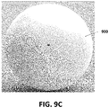
- the parallel grooves 506 serve as air channels or air pockets when the panel is bonded to the bladder 800 enclosed in carcass as depicted in Fig. 9C .
- the air channels can increase the softness and groove formation at joints when bladder pressure is applied at the center of an exemplary panel P.
- the flange area of the first lining layer 503 can be cut at from approximately 2-4 mm to the edges by hot blade of an automatic machine to create flanges 507 within the flange area 505, at each side of the panel P as depicted in Fig. 5D .
- the cut path can intersect the grooves 506, and intersect at preferably a right angle.
- the flanges 507 turn inside and are bonded to the first lining layer 503 in a manner to make the inner surface and the abutting edges 508 of the first lining layer 503 coplanar as illustrated in Fig. 5E .
- the inside turning of the flanges can be achieved by applying heat and/or pressure using a machine.
- the thickness of the casing 501 and first lining layer 503 can be from approximately 0.5-2.0 mm and 1.5-6.5 mm, respectively, within the exemplary panel P; however, the collective thickness should not exceed 8.5 mm.
- the casing 301 or 501 material can be selected from artificial leather, polyvinyl chloride (PVC), polyurethane (PU) or thermoplastic polyurethane (TPU) or the like, while the first lining layer 303 or 503 and/or additional (second) lining layer 305 can be comprised of foam, and the foam or foaming member can be comprised or formed of one or more materials selected from chloroprene (CR), polyurethane (PU), ethylene vinyl acetate (EVA), polyethylene (PE), polyvinyl chloride (PVC), polystyrene, polyolefin, ethylene propylene diene monomer (EPDM), polyolefin elastomer (POE), thermoplastic elastomer (TPE), natural foam, artificial foam, and/or hybrid foam.
- the adhesive 202, 302, 304 can independently be selected from water-based natural adhesive, synthetic adhesive, and/or the like.
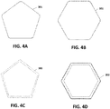
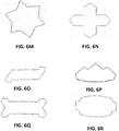
- Figs. 6A-6R illustrates various shapes of the exemplary panel P.
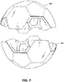
- Fig 7 illustrates the arrangement of exemplary panels P bonded or attached through the abutting edges by an adhesive to form substantially hemispherical shells 700 and 701.
- each hemispherical shell 700 and 701 can comprise 16 exemplary panels P, wherein one hemispherical shell has a valve panel that is bonded with the valve 801 of the bladder 800.
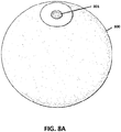
- Fig. 8A illustrates an exemplary zero wings bladder 800 having a valve 801 therein.
- the bladder 800 can be made from a rubber or carbon latex material or by any natural or synthetic monomer or polymer.
- the bladder can optionally be covered or coated with a thin layer of a chemical or polymer having an elastic property like rubber, and can retain the air for much more time in the inflated bladder to increase the durability of an inflated sports ball by utilizing it.
- the coated thin layer of monomer or polymer helps to reduce the permeability of the bladder, maintaining pressurized air within, and not outwardly, helping to reduce escape of air from the interior of the bladder, and decreasing the air loss to from approximately 10-15% within 72 hours, tested as per the protocol set by FIFA.
- Other hanging bladder embodiments can be selected from four wings bladders, seven wings bladders, or multiple wings bladders, or the like.
- Figs. 8B-8E illustrate enlarged cross-sectional views of the valve 801 that has the double lock mechanism or system therein.
- the valve 801 can be comprised of valve housing 802, valve heart 803, and a fabric patch 804.
- the valve housing 802 can comprise a U-shaped structure 805 that has a cavity 806, wherein the valve heart 803 can be inserted and fixed, and an umbrella-like circular collar 807 as depicted in Fig. 8E .
- the valve heart 803 can have a tube-like aperture 808 that can guide the nozzle of the device or tool used to insert the pressurized air within the bladder 800.
- the depth of the aperture 808 preferably does not exceed approximately 12 mm. 20
- the valve heart 803 can be inserted into the valve housing 802 manually or by using a machine.
- a fabric patch 804 can be circular in shape, having a hole or aperture 809, and can be laminated or bonded to the collar 807 of the valve housing 802 in a manner that tube-like aperture 808 and hole 809 hole are coincidental or coaxial.
- the fabric patch 804 can increase the bonding of the valve in the bladder 800 to the valve panel.
- the valve panel can for example be pentagonal or hexagonal in shape. A preferable shape for the valve panel is pentagonal.
- the remaining area of the collar 807 where fabric patch 804 is not bonded can be tapered to avoid protrusion in the valve panel during play or strike test and for coinciding with the shell of bladder 800.
- the nozzle can be passed through an aperture 808 and extend inwardly by generating two new holes/apertures 810A and 810B at the bottom of valve heart 803 and U-shaped structure 805 respectively, to insert pressurized air in the bladder 800.
- the holes 810B and 810A can serve as first and second locks for the pressurized air, and not allow the air to come out from the bladder 800 through valve 801.
- Fig. 9A illustrates an exemplary empty fabric carcass 900
- Fig. 9B a fabric carcass 900 surrounding the bladder 800 prior to closure and after closing.
- Fig 9C illustrates an exemplary bladder 800 (not shown because it is) surrounded by the carcass 900 and its cross-sectional views ( Figs. 9D-9E ).
- the carcass 900 can be manufactured/prepared by bonding or laminating the number of fabric pieces in an overlapping manner manually or by machine.
- the outer surface of the bladder 800 and inner surface of the carcass 900 can be coated with an anti-adhesive chemical to prevent bonding thereof.
- the carcass 900 can, in an exemplary embodiment, only be bonded to the bladder through the valve 801 of the bladder 800.
- the bladder 800 surrounded by the fabric carcass 900 can optionally be passed through a machine to remove wrinkles, if found on the surface of the carcass 900.
- the innermost surfaces of the exemplary panels P of each hemispherical shell can be laminated by an adhesive and placed in upper and lower portions of a ball-forming molding machine, wherein one portion can have the valve panel.
- the bladder depicted in Fig. 9C can be placed in accordance with the valve panel to form the exemplary sports ball of the present invention by applying other features or steps of the thermo-bonding technique as conventionally followed.
- the seam of the sports ball can further be protected by an adhesive to reduce the water uptake in such conditions set by the
- all bonding or attachments can be achieved by an adhesive.
- the adhesive can independently be selected from the group consisting of water-based natural adhesive, synthetic adhesive, or the like.
- the inflated sports ball can be optionally passed through a molding process to attain the round shape of the ball. Resultantly, the sports ball manufactured by this process is extra soft with excellent performance as to feel, stability, durability, playability, flight and other aerodynamic characteristics of the professional ball, and further meets the international standards for a match ball.
Landscapes
- Health & Medical Sciences (AREA)
- General Health & Medical Sciences (AREA)
- Physical Education & Sports Medicine (AREA)
- Professional, Industrial, Or Sporting Protective Garments (AREA)
Description
- The present invention relates to a ball, materials utilized in its construction, its arrangements, and a method of manufacturing thereof. More specifically, the present invention relates to a sports ball like a soccer ball, basketball, American football or rugby ball, futsal ball or other similar game ball.
- Conventionally, there are two types of inflatable sports ball available. Each type mainly comprises an elastic bladder, a restriction layer bonded with the bladder, and casing material with or without lining layers. The differences between the two types resides in the differences between having a lining layer-a stitched (machine or hand) ball, or not having such a layer-a laminated or thermo-bonded ball. A variety of techniques and methods have been utilized to manufacture such sports balls that would have the qualities of a match or professional ball.
- A conventional stitched ball has many drawbacks related to cost, time and quality (e.g. durability) of the ball. The hand-stitched ball is comparatively expensive and requires a highly-skilled labor force and prolonged manufacturing processes, and thus it is not cost efficient today, and costs are only constantly increasing every year.
- A machine stitched ball is cheaper in construction than a hand-stitched ball, requires a shorter process of manufacturing and is more cost effective. Both types of stitched balls still have many disadvantages, including loose or exposed stitching, high water uptake, poor performance of the ball and hardness at the seams due to use of thread for stitching. Another disadvantage lies in the fact that once a single stitch is broken, likely the entire chain of stitches opens or loosens.
- Currently, sports balls, particularly soccer balls, are also under a lot of criticism due to the rising rate of concussions due to hardness of the ball, particularly in youth and women players. In the conventional sports ball, such hardness is mainly caused due to the presence of stitching at the seams or abutting edges, and the use of a bonded bladder, the bonding of restriction layer and bladder surface, decreases the softness or elasticity of the bladder and makes it harder such that concussion during head strike of the ball are not uncommon.
- Many sports ball manufacturers use outdated bladder technology for machine stitched, hybrid, and thermo-bonded balls in which the bladder is wound with thread using an adhesive, resulting in a so-called "thread-wound bladder". This combination of thread and bladder become essentially unified into a single unit due to the use of adhesive. Once the bladder is deflated or inflated, the thread deflates or inflates with the bladder shell as they have become one construction. This results in the outer shell of the bladder being very hard in an inflated condition.
- Another method of construction uses patches of fabric that are attached directly onto the bladder shell via adhesive. Once attached, the bladder shell and fabric patches similarly become a unified construction of bladder/patches resulting in a very hard bladder. When a pasted fabric bladder is deflated or inflated, the fabric deflates or inflates along with the shell. This method similarly results in a hard-shell bladder since fabric, adhesive and bladder shell act as one unit.
- The thermo-bonding manufacturing method is comparatively fast, and due to the absence of stitching, the ball is relatively soft at the abutting edges. But there is still a need to soften the ball from edges and the bladder shell to help decrease the rate of concussions caused during head strike.
-
US Patent No. 7,749,116 discloses a method of manufacturing a ball using a thermo-bonding technique in which panels of a ball-comprised of casing and a thickness adjusting member (i.e. foam)-are bonded together through adhesive. The peripheral edges or flange areas of the panel are turned inside by cutting the panel from the vertices and bonding adjacent panels through abutting edges under heat and pressure. It includes one of the fastest methods to form panels to manufacture a thermo-bonded ball. -
US Patent No. 6,685,585 discloses a skiving method where edges of a leather panel or casing are skived at a certain degree and then joined together. As disclosed, thickness adjusting member foam, fabric or a combination thereof is smaller than the leather panel or casing and peripheral edges of the leather panel are turned inside without applying heat, resulting in formation of soft edges as compared to the aforementioned method. However, the skiving method is very slow and costly. This is a very slow process and the placement of foam in the center to leave an equal portion of the casing for turning is very difficult and usually not practically observed with a high rate of accuracy. - A disadvantage of these methods includes that once the bladder is inflated, the fabric or thread-wound bladder shell directly touches the seams/T-junction of the outer shell. Of course, once the bladder directly touches at the seams, then the seams become hard, and use of such a ball can result in concussions. Thus, a need has arisen in the art to soften the panels from the abutting edges and/or to reduce the stress on the seams/T-junction.
- A disadvantage of these methods includes that the ball has a very low groove at its seams, resulting in the loss of defined trajectory, as well as instability of ball in the air. Low groove seams create less drag, which gives players unpredictable results after kicking.
- The football manufacturers have also been facing another problem related to a high rate of air loss or air leakage from an inflated ball. The rate of air leakage is generally observed to be from ten to fifteen percent (10%-15%) within seventy-two hours (72 hrs.) of full inflation, which also affects the durability of the ball. Due to such a property of the elastic/rubber bladder, there is a need to re-inflate the ball using an inflation tool in a repeated manner.
- Thus, a need has arisen in the art to find innovative techniques related to the composition, configuration, and/or position of construction materials within the panels of a ball. Further, what is needed is an inventive method of manufacturing such a ball, to resolve, minimize and/or eliminate the problems found in conventional manufacturing. It is an intention of the present invention to provide such innovations in ball manufacturing technology and ball construction.
-
US 9586098 B1 -
US 2012/283055 A1 discloses a sport ball that may include a casing, a bladder, and a valve. The casing forms at least a portion of an exterior surface of the ball. The bladder is located within the casing for enclosing a pressurized fluid, and the bladder may be formed from a material that includes a first layer of thermoplastic polymer material and a second layer of a barrier material. The valve is for introducing the fluid to the bladder, and the valve is secured to the bladder and accessible from an exterior of the casing. A tie layer may be located between the flange and a surface of the bladder to join the flange to the bladder. -
BG 64273 B1 -
US 9011621 B1 - Briefly described, the present invention relates to a sports ball comprising the features of
claim 1. - The present invention also relates to a method of manufacturing a sports ball comprising the features of claim 11.
- One object of the present invention is to provide a soft sports ball with excellent performance, namely in feel, stability, durability, playability, flight and other aerodynamic characteristics of the match or professional ball.
- Another object of the present invention is to reduce if not remove the rate of concussion caused by the hardness known with the conventional ball's panels, particularly at their edges or seams, by utilizing an innovative composition and structure, configuration and positions of the materials (casing lining layer) within the panels.
- Another object of the present invention is to reduce the hardness known with the conventional ball originating due to the use of a bonded bladder e.g. fabric wrapped and thread-wound bladder, by introducing a hanging bladder and/or its distinctive arrangement of the bladder and carcass within the ball.
- Another object of the present invention is to provide a solution to reduce the conventional air leakage from the inflated bladder of the finished ball by introducing a valve having a double lock mechanism/system into the bladder and/or coating of a monomer/polymer on the outer surface of the bladder.
- Another object of the present invention is to provide a unique method of manufacturing a good quality sports ball that reduces the time of manufacturing relative to the time conventionally required.
- These and other objects, features and advantages of the present invention will become more apparent upon reading the following specification in conjunction with the accompanying drawing figures.
-
-
Figs. 1A-1C illustrates specific/average-sized sheets of the casing or top layer, first lining layer and second lining layer of the present invention, according to an exemplary embodiment. -
Fig. 2 illustrates specific-sized sheets wherein the casing and first lining layer sheets are bonded or laminated together according to an exemplary embodiment of the present invention. -
Figs. 3A-3C illustrate an enlarged cross-sectional view of an exemplary panel comprising a casing, first lining layer and second lining layer of the present invention, according to an exemplary embodiment of the present invention. -
Figs. 4A-4I illustrate a method of manufacturing an exemplary panel of the present invention, wherein the casing and first lining layer are not in equal in size and bonded or laminated together and further bonded to second lining layer, according to an exemplary embodiment of the present invention. -
Fig. 5A illustrates an enlarged cross-sectional view of another exemplary panel comprising a casing and first lining layer according to an exemplary embodiment of the present invention. -
Figs. 5B-5E illustrate a method of manufacturing another exemplary panel, wherein the casing and first lining layer are equal in size and bonded or laminated together, according to an exemplary embodiment of the present invention. -
Figs. 6A-6R illustrate various shapes of exemplary panels of exemplary embodiments of the present invention. -
Fig. 7 illustrates an arrangement of exemplary panels joined at the abutting edges through an adhesive to form substantially hemispherical shells of the sports ball according to an exemplary embodiment of the present invention. -
Fig. 8A illustrates an exemplary zero wing bladder having the valve therein according to an exemplary embodiment of the present invention. -
Figs. 8B-8E illustrates cross-sectional views of the valve that has a double lock mechanism according to an exemplary embodiment of the present invention. -
Fig. 9A illustrates an exemplary fabric carcass with and without enclosing a bladder according to an exemplary embodiment of the present invention. -
Fig. 9B illustrates an exemplary fabric carcass with an exposed bladder before to close it according to an exemplary embodiment of the present invention. -
Fig. 9C illustrates an exemplary fabric carcass wrapped hanging bladder according to an exemplary embodiment of the present invention. -
Figs. 9D-9E illustrate a cross-sectional view of an exemplary fabric carcass wrapped inflated hanging bladder according to an exemplary embodiment of the present invention. - To facilitate an understanding of the principles and features of the various embodiments of the invention, various illustrative embodiments are explained below. Although exemplary embodiments of the invention are explained in detail, it is to be understood that other embodiments are contemplated. Accordingly, it is not intended that the invention is limited in its scope to the details of construction and arrangement of components set forth in the following description or illustrated in the drawings. The invention is capable of other embodiments and of being practiced or carried out in various ways. Also, in describing the exemplary embodiments, specific terminology will be resorted to for the sake of clarity.
- Ranges may be expressed herein as from "about" or "approximately" or "substantially" one value and/or to "about" or "approximately" or "substantially" another value. When such a range is expressed, other exemplary embodiments include from the one value and/or to the other value.
- Similarly, as used herein, "substantially free" of something, or "substantially pure", and like characterizations, can include both being "at least substantially free" of something, or "at least substantially pure", and being "completely free" of something, or "completely pure".
- By "comprising" or "containing" or "including" is meant that at least the named compound, element, particle, or method step is present in the composition or article or method,
but does not exclude the presence of other compounds, materials, particles, method steps, even if the other such compounds, material, particles, method steps have the same function as what is named. - It is also to be understood that the mention of one or more method steps does not preclude the presence of additional method steps or intervening method steps between those steps expressly identified. Similarly, it is also to be understood that the mention of one or more components in a composition does not preclude the presence of additional components than those expressly identified.
- In preferred embodiments, discussions and accompanying figures disclose various construction materials, their unique arrangement and method relating to the manufacture of panels and the sports ball.
- For demonstration and simplicity, a thirty-two-panel sports ball is depicted to show the innovative specifications, materials, their arrangements, techniques, and manufacturing processes of the present invention, but those of skill in the art will understand that similar specifications and technologies also can be applied to various other types of inflatable sports balls having different purposes and configurations.
- For example, the present invention can comprise an inflatable ball having various numbers of panels, including from two, three, four, six, eight, 10, 12, 14, 20, 21, 24 and 32 panels, and include a variety of ball types, for example, a soccer ball, football, basketball or handball, volleyball, futsal ball, and others.
- In the present invention, an exemplary football comprises 32 panels (i.e. 20 hexagons and 12 pentagons) to form a sports ball.
- The scope of the invention is defined in the appended claims.
-
Figs. 1A-1C illustrate exemplary average-sized casing (or top layer sheet) S1, a first lining layer sheet S2 and an additional (second) lining layer sheet S3 that may be obtained from a larger sheet of materials. -
Fig. 2 illustrates an exemplary average-sized composite sheet S4 that is formed by bonding the casing sheet S1 and first lining layer sheet S2 via an adhesive 202. The application of an adhesive 202 can be achieved manually or by machine. -
Fig. 3A illustrates an enlarged cross-sectional view of an exemplary panel P, wherein afirst lining layer 303 can have a similar shape, but be smaller in size as compared to thecasing 301, and is bonded together to casing 301 by an adhesive 302. Theperipheral area 310 of thecasing 301 can correspond to a thickness of abutting edges of thelining layer 303, but not be more than approximately 6.5 mm, which may be turned inside and bonded with the abutting edges of thefirst lining layer 303. -
Fig. 3B illustrates a cross-sectional view of an exemplary panel P, wherein an additional (second) lininglayer 305 can have similar shape and size of thefirst lining layer 303 and be further bonded to thefirst lining layer 303 by an adhesive 304. Theperipheral area 310 of thecasing 301 can correspond to the sum of the thickness of the abutting edges of thelining layer 303 and additional (second) lininglayer 305, but not more than approximately 6.5 mm. Theperipheral area 310 is turned inside and bonded with the abutting edges of the first and second lining layers 303 and 305. -
Fig. 3C illustrates the cross-sectional view of an exemplary panel P, wherein the additional (second) lininglayer 305 can have similar shape, but smaller size (for example not
more than from approximately 0.5-9.5 mm) from thefirst lining layer 303, and be further bonded to thefirst lining layer 303 by the adhesive 304. Theperipheral area 310 of thecasing 301 can corresponds to the sum of the thickness of the abutting edges of thefirst lining layer 303 and additional (second) lininglayer 305, but not more than approximately 6.5 mm. Theperipheral area 310 is turned inside and bonded with the abutting edges of first and second lining layers 303 and 305. - In the panel P of
Fig. 3C , anair cavity 311 can be formed betweencasing 301 and abutting edges of additional (second) lininglayer 305 due to size differences between the first and second lining layers. Thisair cavity 311 can provide excellent softness and groove formation at joints of an exemplary embodiment of the present invention. Theair cavity 311 can further aid inside movement of the joints when the bladder exerts pressure in the middle of the exemplary panel P. -
Figs. 4A-4I illustrate a method of manufacturing an exemplary panel P depicted inFigs.3A to 3C . - In an exemplary panel P, casing 301,
first lining layer 303 and an additional (second) lininglayer 305 can obtained by cutting their respective average-sized sheets S1, S2 and S3 into shapes depicted inFigs. 4A-4B, 4C-4D and4E-4F respectively. - In an exemplary panel P, casing 301 and
first lining layer 303 are bonded or laminated together by adhesive 302 (not shown), as depicted inFig. 4G . As shown, theperipheral area 310 of thecasing 301 can include anotch 300 at one or more corners so turning or folding can more easily be performed. Thefirst lining layer 303 can have perforatedlines 306, defined at for example from approximately 2.0-4.0 mm from its edges, to increase the softness, adhesion and groove formation at joints-like a hand stitched ball when bladder pressure is applied to it. - In an exemplary panel P, the additional (second) lining
layer 305 can have a similar shape and size to thefirst lining layer 303 and can further be bonded with the adjacentfirst lining layer 303 through adhesive 304 (not shown), as depicted inFig. 4H . - The additional (second) lining
layer 305 can be similar in shape but have a smaller size, (for example not more than from approximately 0.5-9.5 mm) as compared to thefirst lining layer 303, and be bonded to the adjacentfirst lining layer 303 through adhesive 304 (not shown), as depicted infigure 4I . - In an exemplary panel P, the additional (second) lining
layer 305 can have perforatedlines 308, defined at for example from approximately 2.0-4.0 mm from the edges to increase the softness, adhesion and groove formation at joints when bladder pressure is applied to it. Theperforated lines perforation 307 of first lining layer and second lining layers can be within the range of from approximately 1.8-2.5 mm, and the distance in their axial directions between two perforations can be approximately 1.5-2.2 mm. - In an exemplary panel P, the additional (second) lining
layer 305 can include circular holes orapertures 309 at for example from approximately 15.0-25.0 mm from one or more corners to increase the adhesion, softness and help to release or vent out trapped air between the two lininglayers circular hole 309 can be approximately 1.5-4.5 mm. - In an exemplary panel P, the
peripheral area 310 of thecasing 301 can be turned inside (inwardly toward the abutting edges of the first and second lining layers), and bonded to the abutting edges of thefirst lining layer 303 or/and additional (second) lininglayer 305 by adhesive 302 (not shown). The inside turning of theperipheral area 310 of thecasing 301 towards the abutting edges of the lining layers can be achieved manually or by applying pressure using a machine. - In an exemplary panel P, the thickness of the
casing 301 can be from approximately 0.5-2.0 mm while thefirst lining layer 303 and additional (second) lininglayer 305 can be from approximately 1.5-6.5 mm and 0.5-2.5 mm, respectively; however, the collective thickness of the panels may not be more than approximately 8.5 mm. - In an exemplary panel P, the
first lining layer 303 and additional (second) lininglayer 305 can optionally be adjacently bonded or joined first, and then bonded with thecasing 301 through adhesive 304 and 302, respectively, to form the exemplary panel P. - In an exemplary panel P, the bonding of
casing 301,first lining layer 303 and additional (second) lininglayer 305 can independently be performed manually or by using machine. The application ofadhesives -
Fig. 5A illustrate an enlarged cross-sectional view of exemplary panel P, wherein thecasing 501 andfirst lining layer 503 are similar in shape and size, and are bonded together by adhesive 502.Flanges 507 are formed by incision of thefirst lining layer 503 at from approximately 2-4 mm from the edges, and turned inside to bond with the abutting edges of thefirst lining layer 503. -
Figs. 5B-5E illustrates a method of manufacturing an exemplary panel P, wherein thefirst lining layer 503 and thecasing 501 are similar in shape and size. - The exemplary panel P can be obtained by cutting the composite sheet S4 as depicted in
Fig. 5B . The casing 501 (not shown), adhesive 502 (not shown) andlining layer 503 can be like thecasing 301, adhesive 202 or 302 andfirst lining layer 303, respectively. - In an exemplary panel P, the bonded
casing 501 andfirst lining layer 503 can have anotch 504 at one or more corners, to facilitate easy inside turning or folding. The structure and purpose of thenotch 504 is likenotch 300. - In an exemplary panel P,
parallel grooves 506 can be defined at the flange area orperipheral area 505 of thefirst lining layer 503, and the flange area orperipheral area 505 can be defined up to from approximately 12-22 mm from the respective edges. Each groove can be perpendicular to the abuttingedges 508 of thefirst lining layer 503 as depicted inFig. 5C . The length of each groove can be from approximately 12-20 mm, while the width can be equal to the distance between two of them, for example, from approximately 1.0-3.0 mm. Theparallel grooves 506 serve as air channels or air pockets when the panel is bonded to thebladder 800 enclosed in carcass as depicted inFig. 9C . The air channels can increase the softness and groove formation at joints when bladder pressure is applied at the center of an exemplary panel P. - In an exemplary panel P, the flange area of the
first lining layer 503 can be cut at from approximately 2-4 mm to the edges by hot blade of an automatic machine to createflanges 507 within theflange area 505, at each side of the panel P as depicted inFig. 5D . The cut path can intersect thegrooves 506, and intersect at preferably a right angle. Theflanges 507 turn inside and are bonded to thefirst lining layer 503 in a manner to make the inner surface and the abuttingedges 508 of thefirst lining layer 503 coplanar as illustrated inFig. 5E . - In an exemplary panel P, the inside turning of the flanges can be achieved by applying heat and/or pressure using a machine. The thickness of the
casing 501 andfirst lining layer 503 can be from approximately 0.5-2.0 mm and 1.5-6.5 mm, respectively, within the exemplary panel P; however, the collective thickness should not exceed 8.5 mm. - In exemplary panels P, the
casing first lining layer layer 305 can be comprised of foam, and the foam or foaming member can be comprised or formed of one or more materials selected from chloroprene (CR), polyurethane (PU), ethylene vinyl acetate (EVA), polyethylene (PE), polyvinyl chloride (PVC), polystyrene, polyolefin, ethylene propylene diene monomer (EPDM), polyolefin elastomer (POE), thermoplastic elastomer (TPE), natural foam, artificial foam, and/or hybrid foam. The adhesive 202, 302, 304 can independently be selected from water-based natural adhesive, synthetic adhesive, and/or the like. -
Figs. 6A-6R illustrates various shapes of the exemplary panel P. -
Fig 7 illustrates the arrangement of exemplary panels P bonded or attached through the abutting edges by an adhesive to form substantiallyhemispherical shells hemispherical shell valve 801 of thebladder 800. -
Fig. 8A illustrates an exemplary zerowings bladder 800 having avalve 801 therein. Thebladder 800 can be made from a rubber or carbon latex material or by any natural or synthetic monomer or polymer. The bladder can optionally be covered or coated with a thin layer of a chemical or polymer having an elastic property like rubber, and can retain the air for much more time in the inflated bladder to increase the durability of an inflated sports ball by utilizing it. - The coated thin layer of monomer or polymer helps to reduce the permeability of the bladder, maintaining pressurized air within, and not outwardly, helping to reduce escape of air from the interior of the bladder, and decreasing the air loss to from approximately 10-15% within 72 hours, tested as per the protocol set by FIFA. Other hanging bladder embodiments can be selected from four wings bladders, seven wings bladders, or multiple wings bladders, or the like.
-
Figs. 8B-8E illustrate enlarged cross-sectional views of thevalve 801 that has the double lock mechanism or system therein. Thevalve 801 can be comprised ofvalve housing 802,valve heart 803, and afabric patch 804. Thevalve housing 802 can comprise aU-shaped structure 805 that has acavity 806, wherein thevalve heart 803 can be inserted and fixed, and an umbrella-likecircular collar 807 as depicted inFig. 8E . Thevalve heart 803 can have a tube-like aperture 808 that can guide the nozzle of the device or tool used to insert the pressurized air within thebladder 800. The depth of theaperture 808 preferably does not exceed approximately 12 mm. 20 - In an exemplary embodiment, the
valve heart 803 can be inserted into thevalve housing 802 manually or by using a machine. Afabric patch 804 can be circular in shape, having a hole oraperture 809, and can be laminated or bonded to thecollar 807 of thevalve housing 802 in a manner that tube-like aperture 808 andhole 809 hole are coincidental or coaxial. Thefabric patch 804 can increase the bonding of the valve in thebladder 800 to the valve panel. The valve panel can for example be pentagonal or hexagonal in shape. A preferable shape for the valve panel is pentagonal. The remaining area of thecollar 807 wherefabric patch 804 is not bonded can be tapered to avoid protrusion in the valve panel during play or strike test and for coinciding with the shell ofbladder 800. - In an exemplary embodiment, the nozzle can be passed through an
aperture 808 and extend inwardly by generating two new holes/apertures valve heart 803 andU-shaped structure 805 respectively, to insert pressurized air in thebladder 800. - After removing the nozzle, the
holes bladder 800 throughvalve 801. -
Fig. 9A illustrates an exemplaryempty fabric carcass 900, andFig. 9B afabric carcass 900 surrounding thebladder 800 prior to closure and after closing. -
Fig 9C illustrates an exemplary bladder 800 (not shown because it is) surrounded by thecarcass 900 and its cross-sectional views (Figs. 9D-9E ). Thecarcass 900 can be manufactured/prepared by bonding or laminating the number of fabric pieces in an overlapping manner manually or by machine. - In an exemplary embodiment, the outer surface of the
bladder 800 and inner surface of thecarcass 900 can be coated with an anti-adhesive chemical to prevent bonding thereof. Thecarcass 900 can, in an exemplary embodiment, only be bonded to the bladder through thevalve 801 of thebladder 800. Thebladder 800 surrounded by thefabric carcass 900 can optionally be passed through a machine to remove wrinkles, if found on the surface of thecarcass 900. - The innermost surfaces of the exemplary panels P of each hemispherical shell can be laminated by an adhesive and placed in upper and lower portions of a ball-forming molding machine, wherein one portion can have the valve panel. The bladder depicted in
Fig. 9C can be placed in accordance with the valve panel to form the exemplary sports ball of the present invention by applying other features or steps of the thermo-bonding technique as conventionally followed. - In an exemplary embodiment of the present invention, the seam of the sports ball can further be protected by an adhesive to reduce the water uptake in such conditions set by the
- FIFA. In an exemplary embodiment, all bonding or attachments can be achieved by an adhesive. The adhesive can independently be selected from the group consisting of water-based natural adhesive, synthetic adhesive, or the like.
- Similarly, for size 4 or size 3 balls, a variety of numbers and configurations of exemplary embodiments may vary according to their requirements, all of which are within the scope of the present invention.
- In an exemplary embodiment, the inflated sports ball can be optionally passed through a molding process to attain the round shape of the ball. Resultantly, the sports ball manufactured by this process is extra soft with excellent performance as to feel, stability, durability, playability, flight and other aerodynamic characteristics of the professional ball, and further meets the international standards for a match ball.
- Numerous characteristics and advantages have been set forth in the foregoing description, together with details of structure and function. While the invention has been disclosed in several forms, it will be apparent to those skilled in the art that many modifications can be made therein without departing from the scope of the invention as set forth in the following claims.
Claims (14)
- A sports ball comprising:a valve (801) having a double-lock mechanism;a hanging or suspended inflatable bladder (800) attached to the valve (801);a carcass (900) surrounding the hanging or suspended inflatable bladder (800) andattached to the valve (801), wherein the inflatable bladder (800) is not fixedly attached to the carcass (900); anda plurality of panels (P) communicative with one another along edges of the panels (P);wherein each panel (P) comprises at least two layers, a casing layer (301, 501) having an outer surface and an inner surface, and a first lining layer (303, 503) having an outer surface and an inner surface;wherein the outer surface of the casing layer (301, 501) forms an exterior surface of the sports ball;wherein the double-lock mechanism of the valve (801) provides two distinct locations of sealing between the inflatable bladder (800) and the exterior surface of the sports ball;wherein the inner surface of the casing layer (301, 501) is communicative with the outer surface of the first lining layer (303, 503);wherein the inner surface of the first lining layer (303, 503) is communicative with an outer surface of the carcass (900); andwherein an outer flange area (505) of the first lining layer (303, 503) comprises a plurality of grooves (506) extending inwardly and oriented perpendicular to a perimeter edge of the outer flange area (505).
- The sports ball of Claim 1, wherein the plurality of panels (P) is communicative with one another along edges of the panels (P) via bonding of the edges;
wherein the inner surface of the casing layer (301, 501) is communicative with the outer surface of the first lining layer (303, 503) via an adhesive (302, 502); and
wherein the inner surface of the first lining layer (303, 503) is communicative with the outer surface of the carcass (900) via an adhesive. - The sports ball of Claim 1, wherein a width of the outer flange area (505) of the first lining layer (303, 503) measured inwardly from perimeter edges of the first lining layer (303, 503) is less than approximately 25 mm.
- The sports ball of Claim 1, wherein a length of each of the plurality of grooves (506) extending inwardly and oriented perpendicular to the perimeter edge is between from approximately 15 to approximately 25 mm; and
wherein a width of each of the plurality of grooves (506) extending inwardly and oriented perpendicular to the perimeter edge is substantially equal to a distance between two adjacent grooves. - The sports ball of Claim 1, wherein a length of each of the plurality of grooves (506) extending inwardly and oriented perpendicular to the perimeter edge is between from approximately 15 to approximately 25 mm; and
wherein a width of each of the plurality of grooves (506) extending inwardly and oriented perpendicular to the perimeter edge is between from approximately 1 to approximately 3 mm. - The sports ball of Claim 1, wherein a shape of each panel (P) comprises a plurality of vertexes or corners; and
wherein the casing layer (301, 501) and the first lining layer (303, 503) has a notch (300, 504) formed at each vertex or corner of the panel (P). - The sports ball of Claim 1, wherein measured inwardly from perimeter edges of the first lining layer (303, 503) prior to forming flanges, a parallel cut is provided between from approximately 2 to approximately 4 mm from the perimeter edges of the first lining layer (303, 503) to form flanges (507) around the perimeter edges of the first lining layer (303, 503);
wherein the flanges (507) are disposed to be turned inwardly and bonded by adhesive to abutting perimeter edges of the first lining layer (303, 503). - The sports ball of Claim 1, wherein a thickness of the casing layer (301. 501) is between from approximately 0.5 to approximately 2 mm; and
wherein a thickness of the first lining layer (303, 503) is between from approximately 1.5 to approximately 6.5 mm. - The sports ball of Claim 1, wherein a thickness of each panel (P) is less than approximately 8.5 mm.
- The sports ball of Claim 1 further comprising one or both of:a barrier coating of an anti-adhesive chemical applied to one or both of an outer surface of the inflatable bladder (800) and an inner surface of the carcass (900) so the inflatable bladder (800) is not fixedly attached to the carcass (900); anda low permeate layer applied to an outer surface of the inflatable bladder (800).
- A method of manufacturing a sports ball comprising:
forming a plurality of panels (P), wherein each panel has a shape comprising a plurality of vertexes or corners, and wherein each panel (P) is formed by:cutting a panel (P) from sheet material comprising a casing layer (301, 501) bonded to a first lining layer (303, 503);forming of grooves (506) extending inwardly and oriented perpendicular to the perimeter edge in an outer flange area (505) of the first lining layer;forming cut lines inwardly from perimeter edges of the first lining layer (303, 503) to form flanges (507) around the perimeter edges of the first lining layer; andturning the flanges (507) inwardly and attaching them to abutting perimeter edges of the first lining layer (303, 503);attaching the panels (P) to one another along edges of the panels so an outer surface of the casing layers (301, 501) forms an outer shell (700, 701) of the sports ball;providing a fabric carcass (900) that surrounds a hanging or suspended inflatable bladder (800);attaching a double-lock valve (801) to the hanging or suspended inflatable bladder (800) and the carcass (900);attaching an outer surface of the carcass (900) to an inner surface of the panels (P); and molding the outer shell of the formed sports ball;wherein the inflatable bladder (800) is not fixedly attached to the carcass (900). - The method of Claim 11, wherein the casing layer (301, 501) is bonded to the first lining layer (303, 503) through an adhesive (302, 502);
wherein each of the grooves (506) extending inwardly and oriented perpendicular to the perimeter edge are parallel to one another; and
wherein the cut lines are perpendicular to the grooves (506) extending inwardly and oriented perpendicular to the perimeter edge. - The method of Claim 12 further comprising forming a notch (300, 504) at each corner or vortex of the plurality of panels.
- The method of Claim 13 further comprising one or both of:coating an outer surface of the bladder (800) with a monomer or polymer coating that resists escape of air from an interior of the bladder; andcoating one or both of an inner surface of the carcass (900) and the outer surface of the bladder (800) with an anti-adhesive chemical so the inflatable bladder (800) is not fixedly attached to the carcass (900).
Applications Claiming Priority (1)
| Application Number | Priority Date | Filing Date | Title |
|---|---|---|---|
| PK51317 | 2017-10-05 |
Publications (2)
| Publication Number | Publication Date |
|---|---|
| EP3473306A1 EP3473306A1 (en) | 2019-04-24 |
| EP3473306B1 true EP3473306B1 (en) | 2020-02-19 |
Family
ID=63787794
Family Applications (1)
| Application Number | Title | Priority Date | Filing Date |
|---|---|---|---|
| EP18198812.2A Active EP3473306B1 (en) | 2017-10-05 | 2018-10-05 | Sports ball and method of manufacturing sports ball |
Country Status (2)
| Country | Link |
|---|---|
| US (1) | US10632346B2 (en) |
| EP (1) | EP3473306B1 (en) |
Families Citing this family (4)
| Publication number | Priority date | Publication date | Assignee | Title |
|---|---|---|---|---|
| CN110393902B (en) * | 2019-08-02 | 2024-06-07 | 陈红维 | Foaming middle tyre and leather ball and manufacturing method thereof |
| CN110645870B (en) * | 2019-09-20 | 2021-05-18 | 湖南航硕体育用品有限公司 | A ball quality detector |
| CN112933558A (en) * | 2021-02-03 | 2021-06-11 | 天长市正牧铝业科技有限公司 | Ethylene-vinyl acetate copolymer sewn football and preparation process thereof |
| US11660508B2 (en) * | 2021-04-28 | 2023-05-30 | Zhangzhou City Guanteng Sports Products Co., Ltd. | Luminous leather for sports ball |
Family Cites Families (15)
| Publication number | Priority date | Publication date | Assignee | Title |
|---|---|---|---|---|
| US2295804A (en) * | 1940-11-12 | 1942-09-15 | C B Webb Company | Valve for inflatable articles |
| TW407060B (en) | 1998-05-22 | 2000-10-01 | Molten Corp | Ball for ball game |
| US6544608B1 (en) * | 1999-10-08 | 2003-04-08 | Satish Jain | Bladder shell for inflatable balls |
| BG64273B1 (en) * | 2001-03-07 | 2004-08-31 | "-енк(r)--вет н Шишм н(r)в" ...' | Rubber valve |
| US6793597B2 (en) * | 2002-09-12 | 2004-09-21 | Jarrar Hussain Awan | Machine stitched soccer balls with floating bladder |
| CN1739826B (en) * | 2004-08-25 | 2014-11-19 | 唐雅芳 | Method for manufacturing leather ball piece |
| DE102007012451B4 (en) * | 2007-03-15 | 2009-09-24 | I-Chen Tsai | Inflatable double bubble ball |
| JP5336756B2 (en) * | 2008-04-17 | 2013-11-06 | 株式会社モルテン | ball |
| JP5689339B2 (en) * | 2011-03-09 | 2015-03-25 | 株式会社ミカサ | Exercise ball |
| US8771115B2 (en) * | 2011-05-04 | 2014-07-08 | Nike, Inc. | Sport ball with an inflation-retention bladder |
| US8926459B2 (en) * | 2012-03-30 | 2015-01-06 | Nike, Inc. | Sport balls and methods of manufacturing the sport balls |
| US9011621B1 (en) * | 2013-11-04 | 2015-04-21 | Ali Hasnain Hussain | Systems and methods for producing a ball |
| US9586098B1 (en) * | 2016-01-12 | 2017-03-07 | Zain-Ul-Abideen Ahsan | Sports ball and method of manufacturing sports ball |
| US20170304685A1 (en) * | 2016-04-22 | 2017-10-26 | Silver Star Enterprises (Pvt.) Ltd. | DPS Sport Ball |
| US9919189B1 (en) * | 2017-01-31 | 2018-03-20 | Mohammed Ejaz Ahmed | Ball with increased flexure and gel fill |
-
2018
- 2018-03-12 US US15/917,957 patent/US10632346B2/en active Active
- 2018-10-05 EP EP18198812.2A patent/EP3473306B1/en active Active
Non-Patent Citations (1)
| Title |
|---|
| None * |
Also Published As
| Publication number | Publication date |
|---|---|
| US10632346B2 (en) | 2020-04-28 |
| US20190105540A1 (en) | 2019-04-11 |
| EP3473306A1 (en) | 2019-04-24 |
Similar Documents
| Publication | Publication Date | Title |
|---|---|---|
| EP3233223B1 (en) | Sports balls | |
| EP3057780B1 (en) | Systems and methods for producing a ball | |
| US9586098B1 (en) | Sports ball and method of manufacturing sports ball | |
| EP3473306B1 (en) | Sports ball and method of manufacturing sports ball | |
| US7749116B2 (en) | Panel of a ball for a ball game, a ball, and methods of making the same | |
| EP3079889B1 (en) | Systems and methods for producing a ball | |
| US9844706B2 (en) | Inflatable game ball panel construction | |
| US10201732B2 (en) | Ball with domed panels | |
| US11794079B2 (en) | American-style football having a reduced MOI | |
| US7503861B2 (en) | Sportsball and method of manufacturing same | |
| US20110165979A1 (en) | Sport Balls And Methods Of Manufacturing The Sport Balls | |
| US10646752B2 (en) | Methods of manufacturing of tri-tech soccer ball | |
| EP3528906B1 (en) | Sport ball and casing defining a major channel and a minor channel | |
| US20100009790A1 (en) | Sports ball and method of manufacturing | |
| WO2009065302A1 (en) | Bladder of sports ball and sports ball with the bladder | |
| EP3162413B1 (en) | A multi-layer gaming object | |
| CN101664594B (en) | Producing method of ball for ball game | |
| WO2026000615A1 (en) | Game ball and manufacturing method therefor | |
| KR20190093655A (en) | Ball with increased curvature |
Legal Events
| Date | Code | Title | Description |
|---|---|---|---|
| PUAI | Public reference made under article 153(3) epc to a published international application that has entered the european phase |
Free format text: ORIGINAL CODE: 0009012 |
|
| STAA | Information on the status of an ep patent application or granted ep patent |
Free format text: STATUS: THE APPLICATION HAS BEEN PUBLISHED |
|
| AK | Designated contracting states |
Kind code of ref document: A1 Designated state(s): AL AT BE BG CH CY CZ DE DK EE ES FI FR GB GR HR HU IE IS IT LI LT LU LV MC MK MT NL NO PL PT RO RS SE SI SK SM TR |
|
| AX | Request for extension of the european patent |
Extension state: BA ME |
|
| STAA | Information on the status of an ep patent application or granted ep patent |
Free format text: STATUS: REQUEST FOR EXAMINATION WAS MADE |
|
| 17P | Request for examination filed |
Effective date: 20190604 |
|
| RBV | Designated contracting states (corrected) |
Designated state(s): AL AT BE BG CH CY CZ DE DK EE ES FI FR GB GR HR HU IE IS IT LI LT LU LV MC MK MT NL NO PL PT RO RS SE SI SK SM TR |
|
| GRAP | Despatch of communication of intention to grant a patent |
Free format text: ORIGINAL CODE: EPIDOSNIGR1 |
|
| STAA | Information on the status of an ep patent application or granted ep patent |
Free format text: STATUS: GRANT OF PATENT IS INTENDED |
|
| INTG | Intention to grant announced |
Effective date: 20190925 |
|
| GRAS | Grant fee paid |
Free format text: ORIGINAL CODE: EPIDOSNIGR3 |
|
| GRAA | (expected) grant |
Free format text: ORIGINAL CODE: 0009210 |
|
| STAA | Information on the status of an ep patent application or granted ep patent |
Free format text: STATUS: THE PATENT HAS BEEN GRANTED |
|
| AK | Designated contracting states |
Kind code of ref document: B1 Designated state(s): AL AT BE BG CH CY CZ DE DK EE ES FI FR GB GR HR HU IE IS IT LI LT LU LV MC MK MT NL NO PL PT RO RS SE SI SK SM TR |
|
| REG | Reference to a national code |
Ref country code: CH Ref legal event code: EP |
|
| REG | Reference to a national code |
Ref country code: DE Ref legal event code: R096 Ref document number: 602018002539 Country of ref document: DE |
|
| REG | Reference to a national code |
Ref country code: AT Ref legal event code: REF Ref document number: 1234264 Country of ref document: AT Kind code of ref document: T Effective date: 20200315 |
|
| REG | Reference to a national code |
Ref country code: IE Ref legal event code: FG4D |
|
| REG | Reference to a national code |
Ref country code: DK Ref legal event code: T3 Effective date: 20200403 |
|
| REG | Reference to a national code |
Ref country code: NL Ref legal event code: FP |
|
| PG25 | Lapsed in a contracting state [announced via postgrant information from national office to epo] |
Ref country code: NO Free format text: LAPSE BECAUSE OF FAILURE TO SUBMIT A TRANSLATION OF THE DESCRIPTION OR TO PAY THE FEE WITHIN THE PRESCRIBED TIME-LIMIT Effective date: 20200519 Ref country code: FI Free format text: LAPSE BECAUSE OF FAILURE TO SUBMIT A TRANSLATION OF THE DESCRIPTION OR TO PAY THE FEE WITHIN THE PRESCRIBED TIME-LIMIT Effective date: 20200219 Ref country code: RS Free format text: LAPSE BECAUSE OF FAILURE TO SUBMIT A TRANSLATION OF THE DESCRIPTION OR TO PAY THE FEE WITHIN THE PRESCRIBED TIME-LIMIT Effective date: 20200219 |
|
| REG | Reference to a national code |
Ref country code: LT Ref legal event code: MG4D |
|
| PG25 | Lapsed in a contracting state [announced via postgrant information from national office to epo] |
Ref country code: HR Free format text: LAPSE BECAUSE OF FAILURE TO SUBMIT A TRANSLATION OF THE DESCRIPTION OR TO PAY THE FEE WITHIN THE PRESCRIBED TIME-LIMIT Effective date: 20200219 Ref country code: SE Free format text: LAPSE BECAUSE OF FAILURE TO SUBMIT A TRANSLATION OF THE DESCRIPTION OR TO PAY THE FEE WITHIN THE PRESCRIBED TIME-LIMIT Effective date: 20200219 Ref country code: LV Free format text: LAPSE BECAUSE OF FAILURE TO SUBMIT A TRANSLATION OF THE DESCRIPTION OR TO PAY THE FEE WITHIN THE PRESCRIBED TIME-LIMIT Effective date: 20200219 Ref country code: IS Free format text: LAPSE BECAUSE OF FAILURE TO SUBMIT A TRANSLATION OF THE DESCRIPTION OR TO PAY THE FEE WITHIN THE PRESCRIBED TIME-LIMIT Effective date: 20200619 Ref country code: GR Free format text: LAPSE BECAUSE OF FAILURE TO SUBMIT A TRANSLATION OF THE DESCRIPTION OR TO PAY THE FEE WITHIN THE PRESCRIBED TIME-LIMIT Effective date: 20200520 Ref country code: BG Free format text: LAPSE BECAUSE OF FAILURE TO SUBMIT A TRANSLATION OF THE DESCRIPTION OR TO PAY THE FEE WITHIN THE PRESCRIBED TIME-LIMIT Effective date: 20200519 |
|
| PG25 | Lapsed in a contracting state [announced via postgrant information from national office to epo] |
Ref country code: RO Free format text: LAPSE BECAUSE OF FAILURE TO SUBMIT A TRANSLATION OF THE DESCRIPTION OR TO PAY THE FEE WITHIN THE PRESCRIBED TIME-LIMIT Effective date: 20200219 Ref country code: CZ Free format text: LAPSE BECAUSE OF FAILURE TO SUBMIT A TRANSLATION OF THE DESCRIPTION OR TO PAY THE FEE WITHIN THE PRESCRIBED TIME-LIMIT Effective date: 20200219 Ref country code: PT Free format text: LAPSE BECAUSE OF FAILURE TO SUBMIT A TRANSLATION OF THE DESCRIPTION OR TO PAY THE FEE WITHIN THE PRESCRIBED TIME-LIMIT Effective date: 20200712 Ref country code: SM Free format text: LAPSE BECAUSE OF FAILURE TO SUBMIT A TRANSLATION OF THE DESCRIPTION OR TO PAY THE FEE WITHIN THE PRESCRIBED TIME-LIMIT Effective date: 20200219 Ref country code: EE Free format text: LAPSE BECAUSE OF FAILURE TO SUBMIT A TRANSLATION OF THE DESCRIPTION OR TO PAY THE FEE WITHIN THE PRESCRIBED TIME-LIMIT Effective date: 20200219 Ref country code: ES Free format text: LAPSE BECAUSE OF FAILURE TO SUBMIT A TRANSLATION OF THE DESCRIPTION OR TO PAY THE FEE WITHIN THE PRESCRIBED TIME-LIMIT Effective date: 20200219 Ref country code: LT Free format text: LAPSE BECAUSE OF FAILURE TO SUBMIT A TRANSLATION OF THE DESCRIPTION OR TO PAY THE FEE WITHIN THE PRESCRIBED TIME-LIMIT Effective date: 20200219 Ref country code: SK Free format text: LAPSE BECAUSE OF FAILURE TO SUBMIT A TRANSLATION OF THE DESCRIPTION OR TO PAY THE FEE WITHIN THE PRESCRIBED TIME-LIMIT Effective date: 20200219 |
|
| REG | Reference to a national code |
Ref country code: AT Ref legal event code: MK05 Ref document number: 1234264 Country of ref document: AT Kind code of ref document: T Effective date: 20200219 |
|
| REG | Reference to a national code |
Ref country code: DE Ref legal event code: R097 Ref document number: 602018002539 Country of ref document: DE |
|
| PLBE | No opposition filed within time limit |
Free format text: ORIGINAL CODE: 0009261 |
|
| STAA | Information on the status of an ep patent application or granted ep patent |
Free format text: STATUS: NO OPPOSITION FILED WITHIN TIME LIMIT |
|
| 26N | No opposition filed |
Effective date: 20201120 |
|
| PG25 | Lapsed in a contracting state [announced via postgrant information from national office to epo] |
Ref country code: AT Free format text: LAPSE BECAUSE OF FAILURE TO SUBMIT A TRANSLATION OF THE DESCRIPTION OR TO PAY THE FEE WITHIN THE PRESCRIBED TIME-LIMIT Effective date: 20200219 Ref country code: IT Free format text: LAPSE BECAUSE OF FAILURE TO SUBMIT A TRANSLATION OF THE DESCRIPTION OR TO PAY THE FEE WITHIN THE PRESCRIBED TIME-LIMIT Effective date: 20200219 |
|
| PG25 | Lapsed in a contracting state [announced via postgrant information from national office to epo] |
Ref country code: PL Free format text: LAPSE BECAUSE OF FAILURE TO SUBMIT A TRANSLATION OF THE DESCRIPTION OR TO PAY THE FEE WITHIN THE PRESCRIBED TIME-LIMIT Effective date: 20200219 Ref country code: SI Free format text: LAPSE BECAUSE OF FAILURE TO SUBMIT A TRANSLATION OF THE DESCRIPTION OR TO PAY THE FEE WITHIN THE PRESCRIBED TIME-LIMIT Effective date: 20200219 |
|
| PG25 | Lapsed in a contracting state [announced via postgrant information from national office to epo] |
Ref country code: LU Free format text: LAPSE BECAUSE OF NON-PAYMENT OF DUE FEES Effective date: 20201005 Ref country code: MC Free format text: LAPSE BECAUSE OF FAILURE TO SUBMIT A TRANSLATION OF THE DESCRIPTION OR TO PAY THE FEE WITHIN THE PRESCRIBED TIME-LIMIT Effective date: 20200219 |
|
| REG | Reference to a national code |
Ref country code: BE Ref legal event code: MM Effective date: 20201031 |
|
| PG25 | Lapsed in a contracting state [announced via postgrant information from national office to epo] |
Ref country code: FR Free format text: LAPSE BECAUSE OF NON-PAYMENT OF DUE FEES Effective date: 20201031 |
|
| PG25 | Lapsed in a contracting state [announced via postgrant information from national office to epo] |
Ref country code: BE Free format text: LAPSE BECAUSE OF NON-PAYMENT OF DUE FEES Effective date: 20201031 |
|
| PG25 | Lapsed in a contracting state [announced via postgrant information from national office to epo] |
Ref country code: IE Free format text: LAPSE BECAUSE OF NON-PAYMENT OF DUE FEES Effective date: 20201005 |
|
| PGFP | Annual fee paid to national office [announced via postgrant information from national office to epo] |
Ref country code: DK Payment date: 20211015 Year of fee payment: 4 |
|
| PG25 | Lapsed in a contracting state [announced via postgrant information from national office to epo] |
Ref country code: TR Free format text: LAPSE BECAUSE OF FAILURE TO SUBMIT A TRANSLATION OF THE DESCRIPTION OR TO PAY THE FEE WITHIN THE PRESCRIBED TIME-LIMIT Effective date: 20200219 Ref country code: MT Free format text: LAPSE BECAUSE OF FAILURE TO SUBMIT A TRANSLATION OF THE DESCRIPTION OR TO PAY THE FEE WITHIN THE PRESCRIBED TIME-LIMIT Effective date: 20200219 Ref country code: CY Free format text: LAPSE BECAUSE OF FAILURE TO SUBMIT A TRANSLATION OF THE DESCRIPTION OR TO PAY THE FEE WITHIN THE PRESCRIBED TIME-LIMIT Effective date: 20200219 |
|
| REG | Reference to a national code |
Ref country code: CH Ref legal event code: PL |
|
| PG25 | Lapsed in a contracting state [announced via postgrant information from national office to epo] |
Ref country code: MK Free format text: LAPSE BECAUSE OF FAILURE TO SUBMIT A TRANSLATION OF THE DESCRIPTION OR TO PAY THE FEE WITHIN THE PRESCRIBED TIME-LIMIT Effective date: 20200219 Ref country code: AL Free format text: LAPSE BECAUSE OF FAILURE TO SUBMIT A TRANSLATION OF THE DESCRIPTION OR TO PAY THE FEE WITHIN THE PRESCRIBED TIME-LIMIT Effective date: 20200219 |
|
| PG25 | Lapsed in a contracting state [announced via postgrant information from national office to epo] |
Ref country code: LI Free format text: LAPSE BECAUSE OF NON-PAYMENT OF DUE FEES Effective date: 20211031 Ref country code: CH Free format text: LAPSE BECAUSE OF NON-PAYMENT OF DUE FEES Effective date: 20211031 |
|
| REG | Reference to a national code |
Ref country code: DK Ref legal event code: EBP Effective date: 20221031 |
|
| GBPC | Gb: european patent ceased through non-payment of renewal fee |
Effective date: 20221005 |
|
| PG25 | Lapsed in a contracting state [announced via postgrant information from national office to epo] |
Ref country code: GB Free format text: LAPSE BECAUSE OF NON-PAYMENT OF DUE FEES Effective date: 20221005 Ref country code: DK Free format text: LAPSE BECAUSE OF NON-PAYMENT OF DUE FEES Effective date: 20221031 |
|
| PGFP | Annual fee paid to national office [announced via postgrant information from national office to epo] |
Ref country code: NL Payment date: 20251030 Year of fee payment: 8 |
|
| PGFP | Annual fee paid to national office [announced via postgrant information from national office to epo] |
Ref country code: DE Payment date: 20251121 Year of fee payment: 8 |